EP2897771B1 - Pressing punch for the production of tiles and the like and method for extracting a thin plate of a pressing punch - Google Patents
Pressing punch for the production of tiles and the like and method for extracting a thin plate of a pressing punch Download PDFInfo
- Publication number
- EP2897771B1 EP2897771B1 EP13792449.4A EP13792449A EP2897771B1 EP 2897771 B1 EP2897771 B1 EP 2897771B1 EP 13792449 A EP13792449 A EP 13792449A EP 2897771 B1 EP2897771 B1 EP 2897771B1
- Authority
- EP
- European Patent Office
- Prior art keywords
- seat
- thin plate
- pushing
- punch
- plate
- Prior art date
- Legal status (The legal status is an assumption and is not a legal conclusion. Google has not performed a legal analysis and makes no representation as to the accuracy of the status listed.)
- Not-in-force
Links
- 238000003825 pressing Methods 0.000 title claims description 16
- 238000004519 manufacturing process Methods 0.000 title claims description 12
- 238000000034 method Methods 0.000 title claims description 6
- 230000005291 magnetic effect Effects 0.000 claims description 17
- 239000012530 fluid Substances 0.000 claims description 8
- 239000000919 ceramic Substances 0.000 claims description 5
- 239000011347 resin Substances 0.000 claims description 4
- 229920005989 resin Polymers 0.000 claims description 4
- 239000003302 ferromagnetic material Substances 0.000 claims description 3
- 238000007789 sealing Methods 0.000 claims description 3
- 239000010410 layer Substances 0.000 description 17
- 239000002344 surface layer Substances 0.000 description 8
- 230000005294 ferromagnetic effect Effects 0.000 description 2
- 239000002184 metal Substances 0.000 description 2
- 230000002093 peripheral effect Effects 0.000 description 2
- 239000000843 powder Substances 0.000 description 2
- 238000007796 conventional method Methods 0.000 description 1
- 239000000696 magnetic material Substances 0.000 description 1
- 238000012423 maintenance Methods 0.000 description 1
- 239000000463 material Substances 0.000 description 1
- 230000000737 periodic effect Effects 0.000 description 1
- 230000000284 resting effect Effects 0.000 description 1
- 238000000926 separation method Methods 0.000 description 1
- 239000007787 solid Substances 0.000 description 1
Images


Classifications
-
- B—PERFORMING OPERATIONS; TRANSPORTING
- B28—WORKING CEMENT, CLAY, OR STONE
- B28B—SHAPING CLAY OR OTHER CERAMIC COMPOSITIONS; SHAPING SLAG; SHAPING MIXTURES CONTAINING CEMENTITIOUS MATERIAL, e.g. PLASTER
- B28B3/00—Producing shaped articles from the material by using presses; Presses specially adapted therefor
- B28B3/02—Producing shaped articles from the material by using presses; Presses specially adapted therefor wherein a ram exerts pressure on the material in a moulding space; Ram heads of special form
-
- B—PERFORMING OPERATIONS; TRANSPORTING
- B28—WORKING CEMENT, CLAY, OR STONE
- B28B—SHAPING CLAY OR OTHER CERAMIC COMPOSITIONS; SHAPING SLAG; SHAPING MIXTURES CONTAINING CEMENTITIOUS MATERIAL, e.g. PLASTER
- B28B17/00—Details of, or accessories for, apparatus for shaping the material; Auxiliary measures taken in connection with such shaping
- B28B17/009—Changing the forming elements, e.g. exchanging moulds, dies
-
- B—PERFORMING OPERATIONS; TRANSPORTING
- B28—WORKING CEMENT, CLAY, OR STONE
- B28B—SHAPING CLAY OR OTHER CERAMIC COMPOSITIONS; SHAPING SLAG; SHAPING MIXTURES CONTAINING CEMENTITIOUS MATERIAL, e.g. PLASTER
- B28B7/00—Moulds; Cores; Mandrels
- B28B7/0002—Auxiliary parts or elements of the mould
- B28B7/0014—Fastening means for mould parts, e.g. for attaching mould walls on mould tables; Mould clamps
- B28B7/002—Fastening means for mould parts, e.g. for attaching mould walls on mould tables; Mould clamps using magnets
-
- B—PERFORMING OPERATIONS; TRANSPORTING
- B30—PRESSES
- B30B—PRESSES IN GENERAL
- B30B15/00—Details of, or accessories for, presses; Auxiliary measures in connection with pressing
- B30B15/02—Dies; Inserts therefor; Mounting thereof; Moulds
- B30B15/026—Mounting of dies, platens or press rams
Definitions
- the present invention relates to an innovative pressing punch for the production of ceramic products such as tiles and a method for extracting a thin plate in a pressing punch.
- pressing punches comprising a metal plate intended to be mounted on a press structure and having a pressing surface lined with a rubber or resin surface layer vulcanized onto the plate and provided with an impression for one side of the product to be produced.
- the surface layer is subject to wear which results in the need for periodic replacement thereof.
- the plate In order to perform replacement, the plate is removed from the press and sent to the manufacturer who will perform removal of the worn layer, vulcanize a new layer and send the plate back again to the client for reassembly on the press.
- the operations of removal and reassembly of the plate from/onto the press require time, owing to the not insignificant weight of the plate itself, therefore resulting in inconvenient stoppage of production.
- the weight of the plate also poses a problem with regard to despatch thereof to/from the manufacturer.
- EP1645380 discloses a pressing punch for the production of ceramic tiles in accordance with the preamble of claim 1 and EP1386705 discloses a mould in which an impressive part is magnetically fixed in the mould.
- EP2394808 discloses a magnetically fixed sliding plates for a pressing station.
- the general object of the present invention is to provide a pressing punch for the production of tiles, which is able to ensure rapid, relatively low-cost and simple replacement of the layer containing the impression of the tile.
- a method for raising the thin plate is also claimed.
- Figure 1 shows a first embodiment of a punch according to the invention, denoted generally by 10.
- the punch is intended to be housed inside a mould 11, between two press surfaces 12 and 13, so as to define a pressing chamber 14 for pressing powders for manufacturing the tile or similar product.
- the punch 10 comprises a base plate or support plate 15 provided at the top with a seat 16 which receives a thin plate 17.
- the plate 15 will have dimensions comparable to those of the conventional punches which the punch according to the invention will replace.
- the base plate will be designed so as to withstand the flexural forces which are produced on it during operation of the press and will be stably secured to the press by means of systems which are known to persons skilled in the art and which, for the sake of brevity, will not be shown or described further here.
- the thin plate has a form substantially matching that of the seat 16 and has, on an outer side, the impression to be transferred onto the tiles.
- the thin plate is advantageously provided, or at least lined at the top, with a surface layer 18 containing the desired impression for the tile.
- This layer may be formed and fixed to the thin plate 17 using a conventional method.
- it may consist of a suitable rubber or resin layer which is bonded, vulcanized or in any case stably fixed onto the thin plate, in a similar manner to that which occurs in general for the rubber layer present on the conventional base plates present in the punches of the prior art.
- the layer 18 is thus firmly attached to the thin plate 17.
- the thin plate may have a suitable thickness sufficient to prevent an unacceptable distortion of the impression. Its exact thickness may therefore also depend on the extension of the impression.
- the thin plate may have a thickness which is comparable with the thickness of the layer.
- the layer may have a thickness ranging from 0.5 mm to 5 mm and the thin plate may have a thickness ranging from 1 mm to 15 mm.
- the base plate instead has a thickness comparable to that of the conventional plates with punches having a layer vulcanized on the heavy plate.
- the thickness of the base plate may be between 17 mm and 50 mm. Different thicknesses are, however, possible for both of them.
- the thin plate with its surface impression forms the removable part of the punch according to the invention.
- Magnetic attraction means are provided between the thin plate and its seat in the base plate in order to perform magnetic fixing once the thin plate is placed in its seat.
- the thin plate is advantageously made of ferromagnetic material or contains suitably distributed parts made of ferromagnetic material and magnets 19 which are correspondingly and suitably arranged in the bottom of the seat 16 inside suitable recesses.
- magnets will be chosen so as to have a force of attraction suitable for keeping the thin plate firmly inside the seat against the normal forces to which the layer 18 is subject during use of the punch.
- the magnets may be arranged spread over or in localized positions on the surface of the seat, depending on their specific magnetic force.
- they may be formed by disks of magnetic material which are arranged in the corners of the seat, in a middle position along the edges of the seat and in certain intermediate zones inside the seat (in particular, advantageously in the centre of the seat and in the centre of each of four quadrants into which the seat is ideally divided).
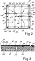
- the seat 16 may have advantageously raised perimetral edges 20 which are inclined outwards and match the peripheral edges 21 of the thin plate 17 with the layer 18, as can be clearly seen in the enlarged view of Figure 3 .
- the thin plate with the surface layer which forms the impression may be advantageously inset in the seat so as to have the impression surface with perimetral edges which are substantially flush with the top edges of the seat, as can be clearly seen in Figure 1 .
- centring parts able to favour further optimum engagement between the two parts.
- These parts may be formed, for example, by projections 31 in the engaging side of the thin plate and matching recesses 32 in the bottom of the seat 16.
- Actuatable pushing means 22 are arranged in the base plate 15 and allow the thin plate to be moved away upon operation from the seat against the retaining action of the magnetic attraction means.
- these pushing means comprise pushing pistons 23 which are seated inside chambers 24 in the base plate.
- the chambers 24 are formed in the base plate on the opposite side to the seat 16 and sealingly closed by suitable stoppers 25, preferably fixed by means of a screw system for easy maintenance.
- Each piston 23 has a pushing end 26 which slides axially inside a passage 27 which emerges in the bottom of the seat 16.
- the piston is movable upon operation between a retracted or rest position, in which the pushing end 26 is retracted so as not to interfere with the thin plate in the seat 16, as shown in Figure 1 , and an advanced or operative position, in which the pushing end 26 is advanced inside the seat 16 and pushes the thin plate so as to raise it from the seat 16, as shown in Figure 3 . Raising is sufficient to detach the thin plate from the magnetic retaining means and allow the thin plate to be gripped with the fingers in order to remove it from the base plate.
- the pistons are operated so as to move by means of a suitable network for supplying them.
- a fluid system with ducts 28 for supplying the pressurised fluid inside the chambers may be advantageously used for the operating movement of the pistons.
- the fluid may be for example compressed air or oil.
- the pistons may also be moved by an electromechanical system, for example of the solenoid type.
- the power supply network may be provided inside the bottom support and comprise a suitable element for connection to the external power source, not shown in that it is known per from the prior art.
- the pistons may also be distributed over the surface of the seat 16, between the magnetic elements, so as to exert a pushing force over the entire thin plate. All the pistons may be advantageously activated simultaneously for their simultaneous movement towards the operating position. In this way the thin plate is uniformly raised from its seat.
- the pistons By deactivating the pushing system, the pistons may be left free to retract owing to the pushing force on them of a thin plate 17 which is inserted manually into the seat and is attracted by the magnets, or advantageously a system for active return of the pistons into the rest position may be provided.
- This active system may comprise, for example, resilient recall elements 29 (for example springs) and/or further ducts 30 for supplying fluid under pressure, so as to create double-acting pistons 23.
- the mutually matching shape of the perimetral edges, seat of the support and removable element ensures centring of the two parts and a suitable finish of the tile edge.
- the old removable element may be stored, if necessary reconditioned with a new surface layer or definitively discarded (in view of its relatively low cost).
- Figure 4 shows a possible alternative embodiment, denoted by 110, of a punch applying the principles of the present invention. Parts similar to those of the previous embodiment will be indicated by the same number, increased by 100.
- a base plate or support plate 115 is thus provided, said plate having on top a seat 116 which receives a thin plate 117 which contains the impression to be formed on the tiles.
- This impression may be again formed by means of a rubber or resin layer 118 which is bonded to the thin plate as described for the previous embodiment.
- Means 119 for mutual magnetic attraction are provided between the thin plate 117 and seat 116 so as to provide a magnetic fixing system once the thin plate is placed inside the seat, as described above.
- the seat 116 may have advantageously raised perimetral edges 120 which are inclined outwards so as to mate with matching peripheral edges 121 of the removable element 117, 118. Further centring means 131, 132 may be provided in order to favour further optimum engagement between the removable element and the seat.
- actuatable pushing means 122 are arranged in the base plate 115 and allow the thin plate to be moved away upon operation from the seat against the retaining action of the magnetic attraction means.
- the pushing means may comprise a pushing piston 123 which is housed inside a chamber 124 in the base plate and provided with a pushing end 126 which slides axially inside a passage 127 which emerges in the bottom of the seat 116 so as to move upon operation the thin plate away from the bottom of the seat.
- the piston may be advantageously operated by means of a fluid system (for example, air or oil system) via ducts 128.
- the pistons may also be moved by an electromechanical system, for example of the solenoid type.
- the pistons may be of the freely retracting type or also assisted by resilient means 129 and/or by a further supply 130 of operating fluid.
- one or more ducts 151 advantageously passing inside the base plate, emerge in the bottom of the base plate, in the interface zone between seat and thin plate.
- These ducts are intended to be connected to a controlled source of pressurised air, so as to inject air directly into the interface between the support consisting of the base plate and the removable element.
- the seat 116 also comprises a perimetral hydraulic sealing element 150.
- This element (for example a seal of suitable shape and material which is seated inside a suitable recess in the bottom of the seat 116 in the vicinity of its edge) bounds, with an improved hydraulic sealing action, the engaging interface between the thin plate and the bottom of the seat 116 where the duct 151 emerges.
- the seal is pliable and has dimensions so as not to hinder resting of the thin plate inside the seat and the mutual magnetic engaging action.
- the advantageous presence of the perimetral seal (which may be suitably deformed) further guarantees the creation of a pressurised chamber under the entire area of the removable element, which is therefore raised and safely released from the magnetically engaged condition.
- the pistons 132 are operated so as to raise the removable element further and/or keep it raised (so that it is not engaged again by the magnets). After the plate has been raised and the pistons 123 form a support for keeping it raised, it is possible to switch off the air supply in the interface.
- the raising pistons may act purely as a support for the removable part (and not necessarily for separating it from the magnets), it is not necessary to use a relatively large number of pistons distributed on the bottom of the seat.
- the manufacturers of the impressions may produce at a lower cost a large number of thin plates with the various impressions, which may be easily stored and despatched to the client, as required.
- the thin plate may also be a non-solid plate, in order to improve fixing of the surface layer.
- it may be perforated in various ways and also shaped, advantageously, in the form of a grille cut from a metal sheet.
- a bottom punch has been illustrated, but it will be obvious to the person skilled in the art that the punch according to the invention may also be a top punch in a press.
- the magnetic attraction means may also comprise magnets in the thin plate which attract ferromagnetic parts in the bottom of the seat.
Landscapes
- Engineering & Computer Science (AREA)
- Mechanical Engineering (AREA)
- Chemical & Material Sciences (AREA)
- Ceramic Engineering (AREA)
- Manufacturing & Machinery (AREA)
- Moulds, Cores, Or Mandrels (AREA)
- Press-Shaping Or Shaping Using Conveyers (AREA)
- Devices For Post-Treatments, Processing, Supply, Discharge, And Other Processes (AREA)
Priority Applications (1)
| Application Number | Priority Date | Filing Date | Title |
|---|---|---|---|
| PL13792449T PL2897771T3 (pl) | 2012-09-21 | 2013-09-05 | Stempel tłoczący do wytwarzania płytek i podobnych oraz sposób wydobywania cienkiej płyty stempla tłoczącego |
Applications Claiming Priority (2)
| Application Number | Priority Date | Filing Date | Title |
|---|---|---|---|
| IT001577A ITMI20121577A1 (it) | 2012-09-21 | 2012-09-21 | Tampone di pressatura per la produzione di piastrelle e simili |
| PCT/IB2013/058300 WO2014045150A1 (en) | 2012-09-21 | 2013-09-05 | Pressing punch for the production of tiles and the like |
Publications (2)
| Publication Number | Publication Date |
|---|---|
| EP2897771A1 EP2897771A1 (en) | 2015-07-29 |
| EP2897771B1 true EP2897771B1 (en) | 2018-10-31 |
Family
ID=47138042
Family Applications (1)
| Application Number | Title | Priority Date | Filing Date |
|---|---|---|---|
| EP13792449.4A Not-in-force EP2897771B1 (en) | 2012-09-21 | 2013-09-05 | Pressing punch for the production of tiles and the like and method for extracting a thin plate of a pressing punch |
Country Status (4)
| Country | Link |
|---|---|
| EP (1) | EP2897771B1 (it) |
| IT (1) | ITMI20121577A1 (it) |
| PL (1) | PL2897771T3 (it) |
| WO (1) | WO2014045150A1 (it) |
Families Citing this family (2)
| Publication number | Priority date | Publication date | Assignee | Title |
|---|---|---|---|---|
| IT201700036509A1 (it) * | 2017-04-03 | 2018-10-03 | I Dea Re S R L | Tampone isostatico per la formatura di piastrelle |
| IT202100026249A1 (it) * | 2021-10-13 | 2023-04-13 | Realmeccanica S R L | Stampo per la compattazione di polveri per la realizzazione di prodotti ceramici |
Family Cites Families (4)
| Publication number | Priority date | Publication date | Assignee | Title |
|---|---|---|---|---|
| ITRE20020061A1 (it) * | 2002-07-29 | 2004-01-29 | Sacmi Molds & Dies S P A | Stampo per piastrelle ceramiche con sostituzione rapida del formato |
| FR2876310A1 (fr) * | 2004-10-07 | 2006-04-14 | Francesco Giglio | Dispositif de reglage pour moule de type a poincon entrant |
| WO2006095254A2 (en) * | 2005-03-09 | 2006-09-14 | Mira Di Algeri Maris | Isostatic pressing means |
| PL2394808T3 (pl) * | 2010-06-10 | 2013-12-31 | Emar S R L | Płyty ślizgowe do stanowiska do prasowania materiałów proszkowych do wytwarzania płytek i tym podobnych, stanowisko do prasowania, w którym stosuje się wspomniane płyty i sposoby wymiany powierzchni ślizgowej wspomnianych płyt |
-
2012
- 2012-09-21 IT IT001577A patent/ITMI20121577A1/it unknown
-
2013
- 2013-09-05 EP EP13792449.4A patent/EP2897771B1/en not_active Not-in-force
- 2013-09-05 WO PCT/IB2013/058300 patent/WO2014045150A1/en not_active Ceased
- 2013-09-05 PL PL13792449T patent/PL2897771T3/pl unknown
Non-Patent Citations (1)
| Title |
|---|
| None * |
Also Published As
| Publication number | Publication date |
|---|---|
| WO2014045150A1 (en) | 2014-03-27 |
| EP2897771A1 (en) | 2015-07-29 |
| PL2897771T3 (pl) | 2019-05-31 |
| ITMI20121577A1 (it) | 2014-03-22 |
Similar Documents
| Publication | Publication Date | Title |
|---|---|---|
| EP3369553B1 (en) | Thermoforming device and thermoforming method | |
| EP2897771B1 (en) | Pressing punch for the production of tiles and the like and method for extracting a thin plate of a pressing punch | |
| MXPA03011458A (es) | Estacion de curvado por prensado y metodo para curvar hojas de vidrio calientes. | |
| CN100473511C (zh) | 从模制工具移走对象的设备和方法 | |
| CN101112800A (zh) | 具有可调节的模切或压痕压力的页张模切及压痕机 | |
| CA2498825A1 (en) | Mechanical press apparatus | |
| EP3138682A1 (en) | Thermoforming apparatus | |
| CN107520945B (zh) | 用于压制陶瓷制品的压实装置 | |
| KR20210032958A (ko) | 기판상에 전자 부품들을 소결하기 위한 소결 프레스에 대한 프레싱 그룹 | |
| EP2130663B1 (en) | Thermoforming machine with an adjustable cover frame | |
| KR20160023565A (ko) | 캐리어 박리 장치 | |
| EP3057768B1 (en) | Mould system for a thermoforming device, thermoforming device, and method for thermoforming a product | |
| EP1453654B1 (en) | A device for processing a three dimensional structure into a substrate | |
| EP3175986B1 (en) | Pneumatic positioning of flatbed laminator roller | |
| EP2394808B1 (en) | Sliding plates for a station for pressing powder materials for manufacturing of tiles and the like, pressing station using said plates and a methods for replacement of the sliding surface of said plates | |
| NL1038268C2 (nl) | Samenstelling voor een thermovormmatrijs. | |
| KR101457871B1 (ko) | 테이프 재단용 금형 | |
| CA2633034A1 (en) | Blank support device | |
| CN202539353U (zh) | 一种新型气动切换机构 | |
| KR101336152B1 (ko) | 3차원 전사장치 | |
| CN105195587A (zh) | 成型地制造具有至少一个构件棱边的板形件的模具和方法 | |
| EP2586580A1 (en) | Adaptable punch for pressing ceramic products such as tiles and the like | |
| EP3915745A1 (en) | Equipment for the manufacture of slabs of ceramic material | |
| JP5184238B2 (ja) | スタンピング成形方法及びスタンピング成形型 | |
| RU2139194C1 (ru) | Штамповочный пресс с упругой матрицей |
Legal Events
| Date | Code | Title | Description |
|---|---|---|---|
| PUAI | Public reference made under article 153(3) epc to a published international application that has entered the european phase |
Free format text: ORIGINAL CODE: 0009012 |
|
| 17P | Request for examination filed |
Effective date: 20150311 |
|
| AK | Designated contracting states |
Kind code of ref document: A1 Designated state(s): AL AT BE BG CH CY CZ DE DK EE ES FI FR GB GR HR HU IE IS IT LI LT LU LV MC MK MT NL NO PL PT RO RS SE SI SK SM TR |
|
| AX | Request for extension of the european patent |
Extension state: BA ME |
|
| DAX | Request for extension of the european patent (deleted) | ||
| STAA | Information on the status of an ep patent application or granted ep patent |
Free format text: STATUS: EXAMINATION IS IN PROGRESS |
|
| 17Q | First examination report despatched |
Effective date: 20170321 |
|
| GRAP | Despatch of communication of intention to grant a patent |
Free format text: ORIGINAL CODE: EPIDOSNIGR1 |
|
| STAA | Information on the status of an ep patent application or granted ep patent |
Free format text: STATUS: GRANT OF PATENT IS INTENDED |
|
| INTG | Intention to grant announced |
Effective date: 20180417 |
|
| GRAS | Grant fee paid |
Free format text: ORIGINAL CODE: EPIDOSNIGR3 |
|
| GRAA | (expected) grant |
Free format text: ORIGINAL CODE: 0009210 |
|
| STAA | Information on the status of an ep patent application or granted ep patent |
Free format text: STATUS: THE PATENT HAS BEEN GRANTED |
|
| AK | Designated contracting states |
Kind code of ref document: B1 Designated state(s): AL AT BE BG CH CY CZ DE DK EE ES FI FR GB GR HR HU IE IS IT LI LT LU LV MC MK MT NL NO PL PT RO RS SE SI SK SM TR |
|
| REG | Reference to a national code |
Ref country code: CH Ref legal event code: EP Ref country code: GB Ref legal event code: FG4D |
|
| REG | Reference to a national code |
Ref country code: AT Ref legal event code: REF Ref document number: 1058823 Country of ref document: AT Kind code of ref document: T Effective date: 20181115 |
|
| REG | Reference to a national code |
Ref country code: DE Ref legal event code: R096 Ref document number: 602013046033 Country of ref document: DE |
|
| REG | Reference to a national code |
Ref country code: IE Ref legal event code: FG4D |
|
| REG | Reference to a national code |
Ref country code: NL Ref legal event code: MP Effective date: 20181031 |
|
| REG | Reference to a national code |
Ref country code: LT Ref legal event code: MG4D |
|
| REG | Reference to a national code |
Ref country code: AT Ref legal event code: MK05 Ref document number: 1058823 Country of ref document: AT Kind code of ref document: T Effective date: 20181031 |
|
| PG25 | Lapsed in a contracting state [announced via postgrant information from national office to epo] |
Ref country code: BG Free format text: LAPSE BECAUSE OF FAILURE TO SUBMIT A TRANSLATION OF THE DESCRIPTION OR TO PAY THE FEE WITHIN THE PRESCRIBED TIME-LIMIT Effective date: 20190131 Ref country code: NO Free format text: LAPSE BECAUSE OF FAILURE TO SUBMIT A TRANSLATION OF THE DESCRIPTION OR TO PAY THE FEE WITHIN THE PRESCRIBED TIME-LIMIT Effective date: 20190131 Ref country code: FI Free format text: LAPSE BECAUSE OF FAILURE TO SUBMIT A TRANSLATION OF THE DESCRIPTION OR TO PAY THE FEE WITHIN THE PRESCRIBED TIME-LIMIT Effective date: 20181031 Ref country code: LT Free format text: LAPSE BECAUSE OF FAILURE TO SUBMIT A TRANSLATION OF THE DESCRIPTION OR TO PAY THE FEE WITHIN THE PRESCRIBED TIME-LIMIT Effective date: 20181031 Ref country code: IS Free format text: LAPSE BECAUSE OF FAILURE TO SUBMIT A TRANSLATION OF THE DESCRIPTION OR TO PAY THE FEE WITHIN THE PRESCRIBED TIME-LIMIT Effective date: 20190228 Ref country code: AT Free format text: LAPSE BECAUSE OF FAILURE TO SUBMIT A TRANSLATION OF THE DESCRIPTION OR TO PAY THE FEE WITHIN THE PRESCRIBED TIME-LIMIT Effective date: 20181031 Ref country code: ES Free format text: LAPSE BECAUSE OF FAILURE TO SUBMIT A TRANSLATION OF THE DESCRIPTION OR TO PAY THE FEE WITHIN THE PRESCRIBED TIME-LIMIT Effective date: 20181031 Ref country code: LV Free format text: LAPSE BECAUSE OF FAILURE TO SUBMIT A TRANSLATION OF THE DESCRIPTION OR TO PAY THE FEE WITHIN THE PRESCRIBED TIME-LIMIT Effective date: 20181031 Ref country code: HR Free format text: LAPSE BECAUSE OF FAILURE TO SUBMIT A TRANSLATION OF THE DESCRIPTION OR TO PAY THE FEE WITHIN THE PRESCRIBED TIME-LIMIT Effective date: 20181031 |
|
| PG25 | Lapsed in a contracting state [announced via postgrant information from national office to epo] |
Ref country code: SE Free format text: LAPSE BECAUSE OF FAILURE TO SUBMIT A TRANSLATION OF THE DESCRIPTION OR TO PAY THE FEE WITHIN THE PRESCRIBED TIME-LIMIT Effective date: 20181031 Ref country code: RS Free format text: LAPSE BECAUSE OF FAILURE TO SUBMIT A TRANSLATION OF THE DESCRIPTION OR TO PAY THE FEE WITHIN THE PRESCRIBED TIME-LIMIT Effective date: 20181031 Ref country code: AL Free format text: LAPSE BECAUSE OF FAILURE TO SUBMIT A TRANSLATION OF THE DESCRIPTION OR TO PAY THE FEE WITHIN THE PRESCRIBED TIME-LIMIT Effective date: 20181031 Ref country code: GR Free format text: LAPSE BECAUSE OF FAILURE TO SUBMIT A TRANSLATION OF THE DESCRIPTION OR TO PAY THE FEE WITHIN THE PRESCRIBED TIME-LIMIT Effective date: 20190201 Ref country code: NL Free format text: LAPSE BECAUSE OF FAILURE TO SUBMIT A TRANSLATION OF THE DESCRIPTION OR TO PAY THE FEE WITHIN THE PRESCRIBED TIME-LIMIT Effective date: 20181031 Ref country code: PT Free format text: LAPSE BECAUSE OF FAILURE TO SUBMIT A TRANSLATION OF THE DESCRIPTION OR TO PAY THE FEE WITHIN THE PRESCRIBED TIME-LIMIT Effective date: 20190301 |
|
| PG25 | Lapsed in a contracting state [announced via postgrant information from national office to epo] |
Ref country code: CZ Free format text: LAPSE BECAUSE OF FAILURE TO SUBMIT A TRANSLATION OF THE DESCRIPTION OR TO PAY THE FEE WITHIN THE PRESCRIBED TIME-LIMIT Effective date: 20181031 Ref country code: DK Free format text: LAPSE BECAUSE OF FAILURE TO SUBMIT A TRANSLATION OF THE DESCRIPTION OR TO PAY THE FEE WITHIN THE PRESCRIBED TIME-LIMIT Effective date: 20181031 |
|
| REG | Reference to a national code |
Ref country code: DE Ref legal event code: R097 Ref document number: 602013046033 Country of ref document: DE |
|
| PG25 | Lapsed in a contracting state [announced via postgrant information from national office to epo] |
Ref country code: SM Free format text: LAPSE BECAUSE OF FAILURE TO SUBMIT A TRANSLATION OF THE DESCRIPTION OR TO PAY THE FEE WITHIN THE PRESCRIBED TIME-LIMIT Effective date: 20181031 Ref country code: EE Free format text: LAPSE BECAUSE OF FAILURE TO SUBMIT A TRANSLATION OF THE DESCRIPTION OR TO PAY THE FEE WITHIN THE PRESCRIBED TIME-LIMIT Effective date: 20181031 Ref country code: SK Free format text: LAPSE BECAUSE OF FAILURE TO SUBMIT A TRANSLATION OF THE DESCRIPTION OR TO PAY THE FEE WITHIN THE PRESCRIBED TIME-LIMIT Effective date: 20181031 Ref country code: RO Free format text: LAPSE BECAUSE OF FAILURE TO SUBMIT A TRANSLATION OF THE DESCRIPTION OR TO PAY THE FEE WITHIN THE PRESCRIBED TIME-LIMIT Effective date: 20181031 |
|
| PLBE | No opposition filed within time limit |
Free format text: ORIGINAL CODE: 0009261 |
|
| STAA | Information on the status of an ep patent application or granted ep patent |
Free format text: STATUS: NO OPPOSITION FILED WITHIN TIME LIMIT |
|
| 26N | No opposition filed |
Effective date: 20190801 |
|
| PG25 | Lapsed in a contracting state [announced via postgrant information from national office to epo] |
Ref country code: SI Free format text: LAPSE BECAUSE OF FAILURE TO SUBMIT A TRANSLATION OF THE DESCRIPTION OR TO PAY THE FEE WITHIN THE PRESCRIBED TIME-LIMIT Effective date: 20181031 |
|
| REG | Reference to a national code |
Ref country code: DE Ref legal event code: R082 Ref document number: 602013046033 Country of ref document: DE Representative=s name: 2K PATENT- UND RECHTSANWAELTE PARTNERSCHAFT MB, DE |
|
| PG25 | Lapsed in a contracting state [announced via postgrant information from national office to epo] |
Ref country code: TR Free format text: LAPSE BECAUSE OF FAILURE TO SUBMIT A TRANSLATION OF THE DESCRIPTION OR TO PAY THE FEE WITHIN THE PRESCRIBED TIME-LIMIT Effective date: 20181031 |
|
| REG | Reference to a national code |
Ref country code: DE Ref legal event code: R119 Ref document number: 602013046033 Country of ref document: DE |
|
| PG25 | Lapsed in a contracting state [announced via postgrant information from national office to epo] |
Ref country code: MC Free format text: LAPSE BECAUSE OF FAILURE TO SUBMIT A TRANSLATION OF THE DESCRIPTION OR TO PAY THE FEE WITHIN THE PRESCRIBED TIME-LIMIT Effective date: 20181031 |
|
| REG | Reference to a national code |
Ref country code: CH Ref legal event code: PL |
|
| PG25 | Lapsed in a contracting state [announced via postgrant information from national office to epo] |
Ref country code: LU Free format text: LAPSE BECAUSE OF NON-PAYMENT OF DUE FEES Effective date: 20190905 Ref country code: IE Free format text: LAPSE BECAUSE OF NON-PAYMENT OF DUE FEES Effective date: 20190905 Ref country code: LI Free format text: LAPSE BECAUSE OF NON-PAYMENT OF DUE FEES Effective date: 20190930 Ref country code: CH Free format text: LAPSE BECAUSE OF NON-PAYMENT OF DUE FEES Effective date: 20190930 Ref country code: DE Free format text: LAPSE BECAUSE OF NON-PAYMENT OF DUE FEES Effective date: 20200401 |
|
| REG | Reference to a national code |
Ref country code: BE Ref legal event code: MM Effective date: 20190930 |
|
| PG25 | Lapsed in a contracting state [announced via postgrant information from national office to epo] |
Ref country code: BE Free format text: LAPSE BECAUSE OF NON-PAYMENT OF DUE FEES Effective date: 20190930 Ref country code: IT Free format text: LAPSE BECAUSE OF NON-PAYMENT OF DUE FEES Effective date: 20190905 |
|
| GBPC | Gb: european patent ceased through non-payment of renewal fee |
Effective date: 20190905 |
|
| PG25 | Lapsed in a contracting state [announced via postgrant information from national office to epo] |
Ref country code: FR Free format text: LAPSE BECAUSE OF NON-PAYMENT OF DUE FEES Effective date: 20190930 Ref country code: GB Free format text: LAPSE BECAUSE OF NON-PAYMENT OF DUE FEES Effective date: 20190905 |
|
| PG25 | Lapsed in a contracting state [announced via postgrant information from national office to epo] |
Ref country code: CY Free format text: LAPSE BECAUSE OF FAILURE TO SUBMIT A TRANSLATION OF THE DESCRIPTION OR TO PAY THE FEE WITHIN THE PRESCRIBED TIME-LIMIT Effective date: 20181031 |
|
| PG25 | Lapsed in a contracting state [announced via postgrant information from national office to epo] |
Ref country code: HU Free format text: LAPSE BECAUSE OF FAILURE TO SUBMIT A TRANSLATION OF THE DESCRIPTION OR TO PAY THE FEE WITHIN THE PRESCRIBED TIME-LIMIT; INVALID AB INITIO Effective date: 20130905 Ref country code: MT Free format text: LAPSE BECAUSE OF FAILURE TO SUBMIT A TRANSLATION OF THE DESCRIPTION OR TO PAY THE FEE WITHIN THE PRESCRIBED TIME-LIMIT Effective date: 20181031 |
|
| PG25 | Lapsed in a contracting state [announced via postgrant information from national office to epo] |
Ref country code: PL Free format text: LAPSE BECAUSE OF NON-PAYMENT OF DUE FEES Effective date: 20190905 |
|
| PG25 | Lapsed in a contracting state [announced via postgrant information from national office to epo] |
Ref country code: MK Free format text: LAPSE BECAUSE OF FAILURE TO SUBMIT A TRANSLATION OF THE DESCRIPTION OR TO PAY THE FEE WITHIN THE PRESCRIBED TIME-LIMIT Effective date: 20181031 |