EP2897162B1 - Einkapselungsstruktur, die teilweise mit Gettermaterial gefüllte Rinnen umfasst - Google Patents
Einkapselungsstruktur, die teilweise mit Gettermaterial gefüllte Rinnen umfasst Download PDFInfo
- Publication number
- EP2897162B1 EP2897162B1 EP14195216.8A EP14195216A EP2897162B1 EP 2897162 B1 EP2897162 B1 EP 2897162B1 EP 14195216 A EP14195216 A EP 14195216A EP 2897162 B1 EP2897162 B1 EP 2897162B1
- Authority
- EP
- European Patent Office
- Prior art keywords
- trenches
- getter material
- substrate
- portions
- face
- Prior art date
- Legal status (The legal status is an assumption and is not a legal conclusion. Google has not performed a legal analysis and makes no representation as to the accuracy of the status listed.)
- Active
Links
- 239000000463 material Substances 0.000 title claims description 249
- 238000005538 encapsulation Methods 0.000 title claims description 73
- 239000000758 substrate Substances 0.000 claims description 140
- 238000000034 method Methods 0.000 claims description 10
- 238000007789 sealing Methods 0.000 claims description 6
- 239000010410 layer Substances 0.000 description 61
- 239000007789 gas Substances 0.000 description 32
- 238000000151 deposition Methods 0.000 description 21
- 230000008021 deposition Effects 0.000 description 16
- 238000010521 absorption reaction Methods 0.000 description 14
- 238000001179 sorption measurement Methods 0.000 description 14
- 238000005530 etching Methods 0.000 description 9
- 238000005086 pumping Methods 0.000 description 8
- 239000011347 resin Substances 0.000 description 7
- 229920005989 resin Polymers 0.000 description 7
- 238000007725 thermal activation Methods 0.000 description 7
- RTAQQCXQSZGOHL-UHFFFAOYSA-N Titanium Chemical compound [Ti] RTAQQCXQSZGOHL-UHFFFAOYSA-N 0.000 description 6
- 238000002161 passivation Methods 0.000 description 6
- 229910052719 titanium Inorganic materials 0.000 description 6
- 239000010936 titanium Substances 0.000 description 6
- 229910052726 zirconium Inorganic materials 0.000 description 6
- QCWXUUIWCKQGHC-UHFFFAOYSA-N Zirconium Chemical compound [Zr] QCWXUUIWCKQGHC-UHFFFAOYSA-N 0.000 description 5
- XKRFYHLGVUSROY-UHFFFAOYSA-N Argon Chemical compound [Ar] XKRFYHLGVUSROY-UHFFFAOYSA-N 0.000 description 4
- 241001080024 Telles Species 0.000 description 4
- 239000010408 film Substances 0.000 description 4
- 238000000206 photolithography Methods 0.000 description 4
- 239000003566 sealing material Substances 0.000 description 4
- VYZAMTAEIAYCRO-UHFFFAOYSA-N Chromium Chemical compound [Cr] VYZAMTAEIAYCRO-UHFFFAOYSA-N 0.000 description 3
- 101100460147 Sarcophaga bullata NEMS gene Proteins 0.000 description 3
- 229910004298 SiO 2 Inorganic materials 0.000 description 3
- 229910052804 chromium Inorganic materials 0.000 description 3
- 239000011651 chromium Substances 0.000 description 3
- 230000001788 irregular Effects 0.000 description 3
- 238000004519 manufacturing process Methods 0.000 description 3
- 238000004806 packaging method and process Methods 0.000 description 3
- 238000005240 physical vapour deposition Methods 0.000 description 3
- 239000011241 protective layer Substances 0.000 description 3
- 239000004065 semiconductor Substances 0.000 description 3
- 229910052710 silicon Inorganic materials 0.000 description 3
- 239000010703 silicon Substances 0.000 description 3
- 239000010409 thin film Substances 0.000 description 3
- ATJFFYVFTNAWJD-UHFFFAOYSA-N Tin Chemical compound [Sn] ATJFFYVFTNAWJD-UHFFFAOYSA-N 0.000 description 2
- 229910052786 argon Inorganic materials 0.000 description 2
- 239000011324 bead Substances 0.000 description 2
- 238000004320 controlled atmosphere Methods 0.000 description 2
- 238000000708 deep reactive-ion etching Methods 0.000 description 2
- 238000009826 distribution Methods 0.000 description 2
- 238000010292 electrical insulation Methods 0.000 description 2
- 230000008020 evaporation Effects 0.000 description 2
- 238000001704 evaporation Methods 0.000 description 2
- 229910052738 indium Inorganic materials 0.000 description 2
- APFVFJFRJDLVQX-UHFFFAOYSA-N indium atom Chemical compound [In] APFVFJFRJDLVQX-UHFFFAOYSA-N 0.000 description 2
- 239000012212 insulator Substances 0.000 description 2
- 238000005304 joining Methods 0.000 description 2
- 229910052743 krypton Inorganic materials 0.000 description 2
- DNNSSWSSYDEUBZ-UHFFFAOYSA-N krypton atom Chemical compound [Kr] DNNSSWSSYDEUBZ-UHFFFAOYSA-N 0.000 description 2
- 230000008018 melting Effects 0.000 description 2
- 238000002844 melting Methods 0.000 description 2
- 239000007769 metal material Substances 0.000 description 2
- 229910000986 non-evaporable getter Inorganic materials 0.000 description 2
- 238000001020 plasma etching Methods 0.000 description 2
- BASFCYQUMIYNBI-UHFFFAOYSA-N platinum Chemical compound [Pt] BASFCYQUMIYNBI-UHFFFAOYSA-N 0.000 description 2
- 229910052782 aluminium Inorganic materials 0.000 description 1
- XAGFODPZIPBFFR-UHFFFAOYSA-N aluminium Chemical compound [Al] XAGFODPZIPBFFR-UHFFFAOYSA-N 0.000 description 1
- 239000012159 carrier gas Substances 0.000 description 1
- 238000004891 communication Methods 0.000 description 1
- 238000007872 degassing Methods 0.000 description 1
- 239000003989 dielectric material Substances 0.000 description 1
- 239000006023 eutectic alloy Substances 0.000 description 1
- 230000002349 favourable effect Effects 0.000 description 1
- 239000011521 glass Substances 0.000 description 1
- PCHJSUWPFVWCPO-UHFFFAOYSA-N gold Chemical compound [Au] PCHJSUWPFVWCPO-UHFFFAOYSA-N 0.000 description 1
- 239000010931 gold Substances 0.000 description 1
- 229910052737 gold Inorganic materials 0.000 description 1
- 229910052751 metal Inorganic materials 0.000 description 1
- 239000002184 metal Substances 0.000 description 1
- 229910001092 metal group alloy Inorganic materials 0.000 description 1
- 150000004767 nitrides Chemical class 0.000 description 1
- 229920002120 photoresistant polymer Polymers 0.000 description 1
- 229910052697 platinum Inorganic materials 0.000 description 1
- 238000007493 shaping process Methods 0.000 description 1
- 239000007787 solid Substances 0.000 description 1
- 238000004544 sputter deposition Methods 0.000 description 1
- 238000009736 wetting Methods 0.000 description 1
- 229910052727 yttrium Inorganic materials 0.000 description 1
Images


Classifications
-
- B—PERFORMING OPERATIONS; TRANSPORTING
- B81—MICROSTRUCTURAL TECHNOLOGY
- B81B—MICROSTRUCTURAL DEVICES OR SYSTEMS, e.g. MICROMECHANICAL DEVICES
- B81B7/00—Microstructural systems; Auxiliary parts of microstructural devices or systems
- B81B7/0032—Packages or encapsulation
- B81B7/0035—Packages or encapsulation for maintaining a controlled atmosphere inside of the chamber containing the MEMS
- B81B7/0038—Packages or encapsulation for maintaining a controlled atmosphere inside of the chamber containing the MEMS using materials for controlling the level of pressure, contaminants or moisture inside of the package, e.g. getters
-
- B—PERFORMING OPERATIONS; TRANSPORTING
- B81—MICROSTRUCTURAL TECHNOLOGY
- B81C—PROCESSES OR APPARATUS SPECIALLY ADAPTED FOR THE MANUFACTURE OR TREATMENT OF MICROSTRUCTURAL DEVICES OR SYSTEMS
- B81C1/00—Manufacture or treatment of devices or systems in or on a substrate
- B81C1/00015—Manufacture or treatment of devices or systems in or on a substrate for manufacturing microsystems
- B81C1/00261—Processes for packaging MEMS devices
- B81C1/00277—Processes for packaging MEMS devices for maintaining a controlled atmosphere inside of the cavity containing the MEMS
- B81C1/00285—Processes for packaging MEMS devices for maintaining a controlled atmosphere inside of the cavity containing the MEMS using materials for controlling the level of pressure, contaminants or moisture inside of the package, e.g. getters
-
- H—ELECTRICITY
- H01—ELECTRIC ELEMENTS
- H01L—SEMICONDUCTOR DEVICES NOT COVERED BY CLASS H10
- H01L23/00—Details of semiconductor or other solid state devices
- H01L23/02—Containers; Seals
- H01L23/10—Containers; Seals characterised by the material or arrangement of seals between parts, e.g. between cap and base of the container or between leads and walls of the container
-
- H—ELECTRICITY
- H01—ELECTRIC ELEMENTS
- H01L—SEMICONDUCTOR DEVICES NOT COVERED BY CLASS H10
- H01L23/00—Details of semiconductor or other solid state devices
- H01L23/16—Fillings or auxiliary members in containers or encapsulations, e.g. centering rings
- H01L23/18—Fillings characterised by the material, its physical or chemical properties, or its arrangement within the complete device
- H01L23/26—Fillings characterised by the material, its physical or chemical properties, or its arrangement within the complete device including materials for absorbing or reacting with moisture or other undesired substances, e.g. getters
-
- H—ELECTRICITY
- H01—ELECTRIC ELEMENTS
- H01L—SEMICONDUCTOR DEVICES NOT COVERED BY CLASS H10
- H01L23/00—Details of semiconductor or other solid state devices
- H01L23/28—Encapsulations, e.g. encapsulating layers, coatings, e.g. for protection
- H01L23/31—Encapsulations, e.g. encapsulating layers, coatings, e.g. for protection characterised by the arrangement or shape
- H01L23/3107—Encapsulations, e.g. encapsulating layers, coatings, e.g. for protection characterised by the arrangement or shape the device being completely enclosed
- H01L23/3121—Encapsulations, e.g. encapsulating layers, coatings, e.g. for protection characterised by the arrangement or shape the device being completely enclosed a substrate forming part of the encapsulation
-
- H—ELECTRICITY
- H01—ELECTRIC ELEMENTS
- H01L—SEMICONDUCTOR DEVICES NOT COVERED BY CLASS H10
- H01L2924/00—Indexing scheme for arrangements or methods for connecting or disconnecting semiconductor or solid-state bodies as covered by H01L24/00
- H01L2924/0001—Technical content checked by a classifier
- H01L2924/0002—Not covered by any one of groups H01L24/00, H01L24/00 and H01L2224/00
Definitions
- the invention relates to an encapsulation structure comprising a hermetically sealed cavity in which at least one micro-device, also called microsystem or microcomponent, is encapsulated, for example MEMS (electromechanical microsystem), NEMS (electromechanical nano-system), MOEMS (opto-electro-mechanical microsystem), NOEMS (opto-electro-mechanical nano-system), or infrared micro-detector type, or more generally any device intended to be encapsulated under a controlled atmosphere, possibly with one or more electronic components, forming for example an integrated circuit, and a getter material.
- MEMS electronic microsystem
- NEMS electromechanical nano-system
- MOEMS electro-electro-mechanical microsystem
- NOEMS optical-electro-mechanical nano-system
- infrared micro-detector type or more generally any device intended to be encapsulated under a controlled atmosphere, possibly with one or more electronic components, forming for example an integrated circuit, and a getter material.
- the invention also relates to a method for encapsulating at least one micro-device for producing such an encapsulation structure.
- micro-devices such as those of the MEMS, NEMS, MOEMS or infrared micro-detector type, require for their proper functioning to be enclosed, or encapsulated, hermetically in a cavity whose atmosphere is controlled. the nature of the gas (s) and the pressure in the cavity).
- Such encapsulation can be performed collectively for several micro-devices made on the same substrate (or wafer), called first substrate.
- first substrate a substrate
- Each of the micro-devices is then encapsulated in a cavity formed by transfer and hermetic sealing of a cover, for example formed by a second silicon or glass substrate, on the first substrate.
- This hermetic assembly between the first substrate and the second substrate called "wafer-to-wafer" (W2W) and collectively forming the encapsulation cavities of micro-devices, allows to protect the atmosphere in the cavities by preventing gas leaks between the interior of the cavities and the external environment.
- W2W wafer-to-wafer
- the cavities may be formed by encapsulation type TFP ("Thin Film Packaging"), or PCM (Thin Film Packaging), the covers being in this case formed of one or more thin layers superimposed and made on the first substrate via the use of a sacrificial material on which the thin layer or layers are deposited.
- TFP Thin Film Packaging
- PCM Thin Film Packaging
- non-evaporable getters in the cavities, for example in the form of solid portions of getter material disposed in these cavities, makes it possible to control the characteristics of the atmosphere within the cavities via a gaseous pumping performed by these cavities.
- the portions of getter material may be made from a thin layer deposition of the getter material made on one or the other of the two substrates, prior to the W2W assembly operation between the two substrates, or from a deposit on the first substrate in the case of encapsulation type TFP.
- a shaping of the portions of getter material in the plane of the surface of the substrate on which the getter material is deposited is then carried out by implementing photolithographic technological operations and etching of the thin layer of getter material.
- the getter material can be produced in the form of a thin layer corresponding to the first layer of the thin film stack of the cover, thus forming the inside wall of the cover defining the cavity. .
- the getter material can be deposited directly on one or the other of the two substrates either through a stencil or by lift-off through a photoresist film previously photolithographically formed, this resin film. being removed after depositing the getter material therethrough.
- the deposited getter is monolithic, of square or rectangular shape and only the face opposite to that in contact with the substrate on which the getter is deposited is in contact with the atmosphere of the cavity.
- the getter can be deposited on the substrate that hosts the device, that is to say the first substrate, or on the second substrate serving as a cover.
- the getter can be deposited either in an identical manner to the preceding case, that is to say on the first substrate, or on the sacrificial layer which makes it possible to construct the cover in thin layers.
- only the face opposite to that in contact with the host substrate or the thin layers of the cap is capable of performing absorption and / or gas adsorption.
- the area necessary for producing the portion of getter material is important.
- the document US 5,921,461 describes an encapsulation structure in which light sensors are encapsulated in a cavity defined between a base and a cover assembled to each other after the deposition of the getter.
- the getter is deposited on the base, in an area that does not include the sensors and not lying opposite transparent windows formed in the hood.
- the getter can in particular be made in the form of a grid, which allows the sensors to be made between the portions of getter material forming the grid.
- the document FR 2,976,933 discloses an encapsulation structure comprising a getter material deposited on a gas permeable material.
- the face of the getter material in contact with the gas-permeable material is accessible and capable of carrying out adsorption and / or gaseous absorption, in addition to the other faces of the getter material.
- this structure makes it possible to obtain an increased gas pumping capacity for a given portion of getter material, this structure is not suitable when the available surface area for achieving the getter is reduced and / or irregular, given the structure monolithic portion of getter material made.
- the documents FR 2 981 059 A1 and US 6,252,294 B1 also disclose encapsulations using getter materials.
- An object of the present invention is to propose an encapsulation structure making it possible to have both a large surface area of getter material exposed in the cavity of the encapsulation structure while requiring only a reduced area of occupancy in the cavity for producing the getter material and / or which is compatible with an irregular reception surface.
- this substrate may correspond to a first substrate on which the micro-device is made and / or to a second substrate forming the hood of the cavity in the case of a W2W assembly between the first substrate and the second substrate
- this substrate may correspond to a first substrate on which the micro-device is made and / or to a second substrate forming the hood of the cavity in the case of a W2W assembly between the first substrate and the second substrate
- the surface of the first portions of getter material disposed on the side walls of these trenches may be greater than the surface of the substrate occupied by these trenches.
- the pumping capacity of the getter material obtained with such an encapsulation structure may be greater than that which would be obtained with a portion of getter material deposited directly on this surface. occupation without trench.
- the production of the first portions of getter material at least on the side walls of the trenches also makes it possible to produce these first portions of getter material on irregular reception surfaces because these first portions of getter material do not require having, at the level of of the substrate, a large, flat and even surface. Indeed, the fact that the trenches are distributed evenly or not in the substrate does not affect the gaseous pumping capacity of the getter material portions formed on the side walls of these trenches.
- the geometry of the trenches produced is also easily adjustable as a function of the absorption and / or gas adsorption needs in the encapsulation structure, and therefore as a function of the deposition area required for the getter material portions to achieve this absorption and or this gas adsorption.
- Such an encapsulation structure is compatible with a W2W type assembly, that is to say via the assembly of two substrates together, or with a TFP type encapsulation.
- the encapsulation structure also makes it possible to reach a high vacuum of the order of 10 -4 to 10 -3 mbar within the cavity.
- each of the trenches communicates with each other, it is possible to access these interior volumes via, for example, a single opening forming a direct access to the interior volume of one of the trenches.
- the first portions of getter material only partially fill the trenches, a part of the volume of the trenches not being occupied by the getter material.
- the trenches can be made in the substrate in a grid pattern such that each trench crosses at least one other trench.
- the encapsulation structure may further comprise one or more second portions of getter material disposed at one or more bottom walls of the trenches.
- This configuration makes it possible to take advantage also of the bottom wall or walls of one or more of the trenches, and thus to have, for the same occupation surface on the substrate, a larger surface of getter material making it possible to achieve absorption and / or adsorption of gas.
- the getter materials of the first and / or second portions of getter material may be chosen for example from zirconium and / or titanium and / or any other metallic material having gas absorption and / or adsorption properties and / or by a combination of these materials.
- the first portions of getter material may partially cover at least one of the trenches at said surface of the substrate.
- the surfaces of the first portions of getter material, and optionally the surfaces of one or more second portions of getter material when such second portions of getter material are formed at the bottom walls of one or more of the trenches, allowing gas pumping can be directly accessible from one or more free spaces between the first portions of getter material disposed on the side walls of a trench.
- the first portions of getter material can completely cover the trenches at said substrate face, and at least one opening can be made through one of the first portions of getter material or through the substrate and communicate with each other. internal volumes of trenches with an interior volume of the cavity. In this case, the surfaces of the first portions of getter material for gas pumping can be accessed from this opening.
- a single opening may, for example, make it possible to bring the first portions of getter material into contact with the atmosphere in the cavity via this opening.
- the opening may be blocked by a plugging material.
- a plugging material corresponding for example to a fusible material, can be used to put the internal volumes of the trenches in communication with the atmosphere of the cavity subsequently to the encapsulation of the micro-device, by releasing the opening of this material. capping (for example by melting the fuse material) after encapsulation.
- This may for example make it possible to release a volume of vacuum (or a particular pressure) or of a particular gas stored in the internal volumes of the trenches at a desired moment, for example to restore a certain level of vacuum or a particular gas pressure during the lifetime of the micro-device, or to activate the pumping function of the portions of getter material at the desired moment, after the completion of the encapsulation structure .
- a rare gas such as argon or krypton stored in the interior volumes of the trenches.
- the getter material can be used to pump the gases other than the rare gases present in the cavity, to arrive at a controlled rare gas atmosphere.
- Such a configuration is advantageous when a resonant micro-device operating under a partial pressure of gas is encapsulated in the cavity.
- the first portions of getter material may cover portions of said substrate face around the trenches. It is thus possible to use the parts of the surface of the substrate to increase the area of getter material exposed to the atmosphere of the cavity.
- the first portions of getter material may comprise columnar grains oriented in a direction forming a non-zero angle and less than 90 ° with the side walls of the trenches. Such an arrangement of the columnar grains of the getter material of the first portions makes it possible to increase the capacity of absorption and / or gas adsorption of the first portions of getter material.
- Dimensions of at least one of the trenches at said substrate face may be smaller than dimensions of said at least one of the trenches at a bottom wall of said at least one of the trenches.
- Such a configuration may advantageously be used when at least one of the trenches is also used as a vacuum or gas reserve to be released later to the realization of the encapsulation structure because with such dimensions, a larger volume of vacuum or gas can be stored in this or these trenches.
- the section of said at least one of the trenches, in a plane perpendicular to said face of the substrate may be of trapezoidal type.
- At least a portion of at least one of the trenches may have a plurality of secondary trenches formed through said face of the substrate, arranged next to each other and whose interior volumes communicate with each other, first portions of getter material that can cover at least part of the side walls of the secondary trenches.
- Such secondary trenches may, for example, be used to increase the area of getter material produced by making the best use of the free surfaces of the substrate, these secondary trenches being for example made at regions of the substrate having a larger free surface than those of the other regions. of the substrate in which the remainder of the trench or trenches without secondary trenches is made.
- the first portions of getter material may be formed by at least a first layer of a first getter material and at least a second layer of a second getter material.
- the second getter material may be different from the first getter material.
- the first layer of the first getter material can completely cover the trenches at said substrate face, and the second layer of the second getter material can cover the first layer of the first getter material.
- the first layer of the first getter material may partially cover the trenches at said substrate face, and the second layer of the second getter material may cover the first layer of the first getter material and completely close the trenches at said face. of the substrate.
- Such an encapsulation process may advantageously be implemented to achieve collective encapsulation of several micro-devices in different cavities to produce a packaging of these micro-devices under a controlled atmosphere.
- FIG. 1 schematically represents an encapsulation structure 100 according to a first embodiment.
- This encapsulation structure 100 is of the W2W type, that is to say is formed by the assembly of a first substrate 102 with a second substrate 104 forming the cover of the encapsulation structure 100, for example every two based on a semiconductor such as silicon, these two substrates 102 and 104 being assembled to one another via a sealing bead 106.
- a cavity 108 is formed by the space obtained between the first substrate 102 and the second substrate 104, the sealing bead 106 forming the side walls of the cavity 108.
- a micro-device 110 for example of the MEMS, NEMS, MOEMS, NOEMS or infrared detector type such as a micro-bolometer, is encapsulated in the cavity 108.
- a getter material 112 for example zirconium and / or titanium or any other metallic material having absorption and / or gas adsorption properties, is also present in the cavity 108, at the level of a hood wall formed by a fac e 113 of the second substrate 104, this face 113 forming an inner wall of the cavity 108.
- the figure 2 schematically represents the encapsulation structure 100 according to a variant of the first embodiment.
- the getter material 112 is formed not on the face 113 of the second substrate 104, but on a face 115 of the first substrate 102 at which it is located. also the micro-device 110 and also forming an inner wall of the cavity 108.
- the getter material 112 is here formed at the periphery of the micro-device 110.
- the encapsulation structure may comprise getter material both on the face 113 of the second substrate 104 and on the face 115 of the first substrate 102.
- the figure 3 schematically represents the encapsulation structure 100 according to a second embodiment.
- the encapsulation structure 100 is not of the W2W type, but of the TFP or PCM type, that is to say has a cover 114 formed of one or more thin layers.
- the getter material 112 is formed on the face 115 of the first substrate 102 on which the micro-device 110 is also located.
- the getter material 112 is made at least partly in trenches, or channels, formed through the face of the substrate at which the getter material 112 is located, that is to say through the face 113 of the second substrate 104 and / or the face 115 of the first substrate 102.
- the trenches are made through the face 115 of the first substrate 102, around the micro-device 110. The characteristics described below in connection with the Figures 4 to 18 also apply when the getter material 112 is formed in trenches made through the face 113 of the second substrate 104.
- the figure 4 is a view from above of a portion of the first substrate 102 of the encapsulation structure 100 previously described in connection with the figure 2 or the figure 3 .
- the getter material is made in the form of portions of getter material 112 covering at least in part (part of the height) the side walls of trenches 116 (the portions of getter material 112 are deposited on upper portions of the side walls of the trenches 116) made through the face 115 of the first substrate 102, in a portion of the thickness of the first substrate 102.
- These trenches 116 are made in the form of a network which corresponds here, in a plane parallel to the face 115 of the first substrate 102 (plane (X, Y) on the figure 4 ), to a grid pattern.
- this grid pattern is formed by vertical trenches 116a, parallel to the Y axis, perpendicularly intersecting horizontal trenches 116b parallel to the X axis.
- the trenches 116 may cross each other in a different pattern, for example a mesh of any shape, polygonal or otherwise. It is also possible to make the trenches 116 as they do not intersect, or to make a single trench 116 for example formed around the micro-device 110.
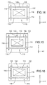
- the figure 5 represents a profile view of a first embodiment of the trenches 116, here corresponding to one of the vertical trenches 116a.
- the dimension along the X axis of the trench 116 shown on the figure 5 corresponds to the width L of this trench 116.
- the portions of getter material 112 are deposited on a portion of the side walls of the trench 116. These side walls of the trench 116 are substantially perpendicular to the face 115 of the first substrate 102.
- the portions of getter material 112 deposited on the side walls of the trench 116 meet at the face 115 and thus completely cover the trench 116 in which the getter material portions 112 are formed.
- the interior of the trench 116 is not accessible from the portions of the trench 116 which are completely covered by the getter material portions 112.
- the getter material portions 112 also cover portions of the face 115 of the first substrate 102. lying around the trench 116.
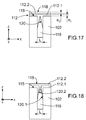
- the figure 17 represents a profile view of a variant of the first embodiment of the trenches 116 previously described in connection with the figure 5 .
- the getter material portions 112 are formed by a first layer 112.1 of a first getter material of thickness e 1 and a second layer 112.2 of a second getter material of thickness e 2 .
- the first layer 112.1 forms the getter material portions deposited on the sidewalls of the trench 116, these portions joining at the face 115 to completely cover the trench 116 at the face 115 of the substrate 102.
- second getter materials of the layers 112.1 and 112.2 are advantageously different one of the other.
- the second layer 112.2 is exposed directly in the cavity 108 of the encapsulation structure 100, while the first layer 112.1 is exposed in the trench 116.
- Such a variant makes it possible in particular to have in the cavity 108 two getter materials having properties different absorption and / or adsorption gas (vis-à-vis the nature of the gases to trap and / or the thermal activation temperature for example).
- the first layer 112.1 comprises, for example, titanium and the second layer 112.2 comprises, for example, zirconium (zirconium having a thermal activation temperature lower than that of titanium).
- the figure 18 represents a side view of another variant of the first embodiment of the trenches 116 previously described in connection with the figure 5 .
- the first layer 112.1 of the first getter material only partially covers the trench 116 at the side 115 of the substrate 102.
- the second layer 112.2 of the second getter material covers the first layer 112.1 and completely closes the trench 116 at of the face 115 of the substrate 102.
- Such a variant is advantageous because it allows the upper part of the trench 116 to be "pre-plugged" with the deposition of the first getter material which covers at least part of the side walls of the trench 116, the second getter material to completely close the trench 116 and cover it.
- This variant makes it possible to increase the width L of the trench 116 to a value equal to approximately twice the thickness of the second layer 112.2 and thus also to increase the depth of the trench 116, for example up to value equal to about sixty times the thickness of the second layer 112.2 when the shape ratio of the trench is equal to about 30.
- Deposition of the portions of getter material 112 along the side walls of the trenches 116 provides a getter material having columnar grains oriented in a direction forming a non-zero angle with the side walls of the trenches.
- Such an arrangement of the columnar grains of the getter material makes it possible to increase the capacity of absorption and / or gas adsorption of the first portions of getter material relative to a getter material conventionally deposited in the form of a monolithic portion on the substrate.
- This access inside the trench 116 can be obtained as soon as the portions of getter material 112 are deposited by not depositing the getter material on this part of at least one of the trenches 116, for example via a "lift” type process. -off "with a dry film, or else subsequent to the deposition of the getter material by making an opening through one of the getter material portions 112.
- the interior volumes trenches 116 communicate with each other. Access to the interior of one of the trenches 116 thus makes it possible to communicate the interior volumes of all the trenches 116 with the atmosphere of the cavity 108. Access to the interior of the trench 116 can also be obtained. by an opening made through one of the portions of getter material 112 or through the substrate 102.
- the encapsulation structure 100 comprising such trenches 116 whose side walls are covered at least in part by the portions of getter material 112 and whose interior volumes communicate with the cavity 108
- absorption and / or gas adsorption is made in the cavity 108 both by a first outer surface 118 of the portions of getter material 112 which is directly exposed in the cavity 108 at the face 115 of the first substrate 102, but also by a second surface 120 portions of getter material 112 located inside the trenches 116, at the side walls of the trenches 116 and exposed to the atmosphere of the cavity 108 via the previously described access, thus forming a large surface of getter material exposed to the atmosphere of the cavity 108 while minimizing the area occupied by the getter material at the face 115 of the first substrate 102.
- the first outer surface 118 corresponds to the upper surface of the second layer 112.2 and the second surface 120 within the trenches 116 corresponds to a surface formed by the first layer 112.1.
- the first outer surface 118 corresponds to the upper surface of the second layer 112.2.
- Layers 112.1 and 112.2 each have a part of their surface, respectively referenced 120.1 and 120.2, exposed in the trenches 116.
- the figure 6 is a side view of a second embodiment of trenches 116, here corresponding to one of the vertical trenches 116a.
- the getter material portions 112 do not completely cover the trenches 116 on which the getter material portions 112 are formed.
- the interior of the trenches 116 is accessible from a space 122 formed between the portions of getter material 112 over the entire length of the trenches 116.
- the portions of getter material 112 also cover portions of the face 115 of the first substrate 102 located around the trenches 116.
- the portions of getter material 112 are also deposited on a portion of the inner side walls of the trenches 116, and more precisely on the upper parts of these side walls.
- the surfaces 118 and 120 of the getter material portions 112 are directly exposed to the atmosphere of the cavity 108 without it being necessary to form subsequently opening through one or more of the getter material portions 112.
- the figure 7 represents a side view of a third embodiment of the trenches 116, here corresponding to one of the vertical trenches 116a.
- second portions of getter material 124 are disposed at the bottom walls of the trenches 116, which further increases the surfaces of getter material exposed to the atmosphere of the cavity 108.
- the portions of getter material 112 are formed by depositing above the trenches 116.
- the fact that the deposited portions of material getter 112 correspond to one or other of these three embodiments depends in particular on the width L with which the trenches 116 are made as well as the thickness e of the portions of getter material 112 deposited.
- the width L of the trench 116 represented on the figure 5 is smaller than that of the trench 116 shown on the figure 6 which itself is smaller than that of the trench 116 shown on the figure 7 .
- the width L of the trenches 116 is for example equal to about 2 times the thickness e of the portions of getter material 112 (or about 2 times the thickness e 1 of the first layer 112.1 in the case of the figure 17 ), this thickness e being for example greater than or equal to about 100 nm, and preferably between about 100 nm and 2 microns.
- the width L of the trenches 116 is for example greater than about 2 times the thickness e of the portions of getter material 112 (or greater than about 2 times the thickness of the first layer 112.1 in the case of the figure 18 ).
- the shape ratio of the trenches 116 corresponding to the depth / width ratio of the trenches 116, may be equal to about 30 and for example between about 15 and 25.
- the figure 8 is a side view of a fourth embodiment of a trench 116, here corresponding to one of the vertical trenches 116a.
- the thickness e of the getter material portions 112 and the width L1 of the trenches 116 are chosen such that the getter material portions 112 completely cover the trenches 116 on which the getter material portions 112 are formed.
- One or more of the trenches 116, or each of the trenches 116 has a lower portion 126 of width L2 greater than the width L1 of the rest of the trench 116.
- the dimensions of the trench 116, at the face 115 of the first substrate 102 are therefore smaller than the dimensions of the trench 116 at a bottom wall of the trench 116, that is to say at the lower part 126.
- the portions of getter material 112 are deposited under a particular atmosphere, for example under vacuum, and access to the interior volumes of the trenches 116 is achieved only after the hermetic encapsulation of the micro-device 110, via the embodiment of an opening as described above, the lower portions 126 of the trenches 116 then form reserves of this particular atmosphere whose contents are added to the atmosphere of the cavity 108 after sealing during the performing the opening, for example vacuum reserves to be added later to the vacuum with which the cavity 108 is hermetically sealed.
- Such trenches 116 are for example made from an SOI substrate (semiconductor on insulator), the trenches 116 being formed firstly through the entire thickness of the upper semiconductor layer of the SOI substrate, the lower portions 126 being then produced by etching the buried insulator layer of the SOI substrate.
- Such trenches 116 that is to say having lower portions 126 of width greater than the remainder of the trenches 116, can also be used for deposits of portions of getter material 112 similar to those previously described in connection with the Figures 6 and 7 .
- the figure 9 represents a side view of a fifth embodiment of the trenches 116, here corresponding to one of the vertical trenches 116a.
- the trench 116 is formed of several secondary trenches made substantially parallel to each other.
- the trench 116 is formed of three secondary trenches 116.1 to 116.3 on which and in which the portions of getter material 112 are deposited (here, as in the first example previously described in connection with FIG. figure 5 that is, completely covering the secondary trenches and covering part of the side walls of the secondary trenches). This subdivision of the trench 116 into several secondary trenches can be done over at least a part of the length of the trench 116.
- Such a configuration has the particular advantage of further increasing the surface of getter material ultimately exposed in the cavity 108, while increasing the "reserve" atmosphere, in terms of gas and / or pressure, that represents the internal volume trenches 116.
- Secondary trenches may communicate with one another, for example by joining one another at a portion of trench 116, as shown in FIG. figure 10 which corresponds to a partial top view of such a trench 116.
- such secondary trenches may be made over the entire length of one or more of the trenches 116, or only part of the length of a trench. or more of the trenches 116 as is the case on the figure 10 . It is also possible that secondary trenches do not communicate with each other.
- each secondary trench comprises an independent access making it possible to communicate the interior of each of the secondary trenches with the cavity 108.
- These accesses are advantageously made at different times, for example depending on the needs in terms of absorption / gas adsorption and / or atmospheric reserve in the cavity 108.
- Such an embodiment of the trenches 116 can be applied for example for a deposit of portions of getter material 112 similar to those previously described in connection with the figure 5 . It is also possible that one or more of the secondary trenches have a lower part wider than the rest of the secondary trench, as previously described in connection with the figure 8 .
- the trenches 116 and / or the secondary trenches are rectilinear. Alternatively, trenches 116 and / or secondary trenches may not be straight.
- the figure 11 is a top view of an exemplary embodiment of a trench 116, a portion of which is connected to three secondary trenches 116.1, 116.2 and 116.3 each of substantially circular or elliptical shape.
- Such an embodiment of the trenches 116 can be applied for deposits of portions of getter material 112 similar to those previously described in connection with the Figures 5 to 7 . It is also possible that one or more of these secondary trenches have a lower portion wider than the rest of the secondary trench, as previously described in connection with the figure 8 .
- flattening and / or electrical insulation of the face 113 or 115 of the substrate on which the getter material portions 112 are deposited may be made by covering the portions of getter material 112 and the remainder of the face 113 or 115 of the substrate by a passivation layer 128 adapted to achieve such flattening and / or such an electrical insulation, for example based on SiN or SiO 2 deposited with a thickness greater than that of the portions of getter material 112, for example between about 1 ⁇ m and 10 ⁇ m (see figure 12 ).
- the material of the passivation layer 128 is selected from the materials which are least favorable to the degassing after deposition and during a rise in temperature of this material.
- Distribution layers (RDL for "Redistribution Layer") forming several metal-insulating levels may also be produced above the face 113 or 115 on which the portions of getter material 112 are located, or above the layer passivation 128.
- the gaseous pumping function is carried out by the portions of the getter material portions 112 located on the side walls of the trenches 116, from the faces 120 of the portions. of getter material 112.
- the getter material portions 112 it is possible to produce, after the deposition of the getter material portions 112, a chemical-mechanical planarization of the getter material with a stop on the face 113 or 115 of the substrate.
- a chemical-mechanical planarization of the getter material with a stop on the face 113 or 115 of the substrate.
- Such an embodiment variant is represented on the figure 13 .
- the plane surface thus obtained can then be used for the implementation of other steps such as the production of a passivation layer or distribution layers.
- Such a planarization can be applied for deposits of portions of getter material 112 similar to those previously described in connection with the Figures 6 and 7 .
- the figure 14 represents a view from above of a portion of the first substrate 102 of the encapsulation structure 100 previously described in connection with the figure 2 or the figure 3 and wherein the getter material portions 112 completely cover the trenches 116.
- an opening 130 is made through the getter material portions 112 formed on one of the trenches 116, thereby communicating the atmosphere of the cavity 108 with the interior volumes of the trenches 116, these interior volumes communicating with each other because the trenches 116 intersect.
- the opening 130 could be made through the face 115 of the first substrate 102.
- Such an opening could in particular be made when the substrate comprising the trenches 116 is of the SOI type, this opening being able to communicate the inside of the trenches 116. with the atmosphere of the cavity 108 by etching a part of the buried dielectric layer thus making it possible to join the interior of one of the trenches 116 with the opening 130 made through the substrate.
- Such a variant can be implemented by selectively etching the buried dielectric material with respect to the getter material.
- a fusible material such as a metal or a metal alloy comprising, for example, indium and / or tin and / or AuSn and or AuSi
- the figure 16 represents another embodiment in which the opening 130 is plugged by a plugging material 134, corresponding for example to a fusible material, before the hermetic encapsulation of the micro-device 110 in the cavity 108.
- This plugging material 134 is realized such that the surface of the opening 130 is slightly smaller than the surface of the sealing material 134 deposited.
- the thickness of the capping material 134 is preferably minimized while remaining sufficient to seal the opening 130.
- it is possible to melt the capping material 134 which then releases the opening 130 in that the plugging material 134 will then spread out by wetting on the getter material, thus exposing the internal volumes of the trenches 116 to the atmosphere of the cavity 108.
- the nature of the plugging material 134 is chosen in particular as a function of the temperature at which the encapsulation is performed, and corresponds for example to a eutectic alloy such as AuSi, AuSn, or AlGe.
- the surfaces 120 of the getter material portions 112 in the trenches 116 are protected from the ambient atmosphere throughout the implementation of the encapsulation process.
- the deposition of the sealing material 134 is carried out under vacuum or under a particular gaseous atmosphere, the interior volumes of the trenches 116 then form vacuum reserves or that particular atmosphere. can be released at any time after the encapsulation of the micro-device 110 in the cavity 108, the amount of these reserves can be adjusted according to the dimensions, including the depth, trenches 116.
- the portions of getter material 112 are thermally activated by exposing the encapsulation structure 100 to a temperature triggering absorption and / or gas adsorption of the getter material.
- This thermal activation temperature of the getter material depends in particular on the nature of the getter material.
- an underlayer of material enabling the temperature of the substrate to be adjusted. thermal activation of the getter material.
- Such an adjustment sub-layer corresponds for example to a layer of chromium and / or platinum and / or aluminum, with a thickness of between approximately 10 nm and 100 nm. The presence of such an adjustment sub-layer under the portions of getter material 112 makes it possible to modify the temperature at which the getter material of the portions 112 is thermally activated, and advantageously makes it possible to lower this temperature of thermal activation.
- a titanium and / or chromium and / or zirconium bonding underlayer can be produced under the adjustment underlayer in order to to improve the adhesion between the material of the first substrate 102 or the second substrate 104 and the material of the adjustment sub-layer. Details of the realization of such a sublayer for adjusting the thermal activation temperature of the getter material and of such a fastening sub-layer are described in the document FR 2 922 202 .
- a protective layer such as a layer of chromium with a thickness of between approximately a few nanometers and 100 nm, or by a nitride or oxide layer obtained by the dry route, as described in the document FR 2 950 876 .
- This protective layer can be removed when the getter material is thermally activated.
- the trenches 116 are first made through the face 115 of the first substrate 102 and / or through the face 113 of the second substrate 104, these substrates being for example based on silicon. These trenches 116 are for example made via the implementation of photolithography and etching steps of the DRIE (deep reactive ion etching) type.
- a hard mask of SiO 2 for example of thickness between about 100 nm and 10 microns, allows for example to engrave trenches 116 whose shape ratio (depth / width) is equal to about 30.
- the portions of getter material 112 are then made on a portion of the lateral flanks of the trenches 116 and completely or partially covering the trenches 116 at the face 113 and / or 115 of the substrate in which the trenches 116 are made.
- the getter material is for example zirconium and / or titanium deposited on a thickness between about 100 nm and 2 microns. Any underlays hooking and adjustment are performed prior to the realization of the portions of getter material 112. It is also possible to deposit a thick adjustment sub-layer, that is to say thick greater than about 100 nm, so as to increase the aspect ratio, or form factor, of the trench and thus promote the closure of the trench by depositing the getter. Such a case can be applied to the configuration previously described in connection with the figure 5 , in this case the implementation of two deposits: one for the adjustment sub-layer and the other for the getter material.
- getter material 112 may be made by lift-off, that is to say by deposition through a resin mask previously produced by photolithography and etching on the face 115 of the first substrate 102 and / or the face 113 of the second substrate 104.
- a dry film of photosensitive resin having a thickness of between approximately 1 and 10 ⁇ m is advantageously used, this thickness possibly being less than approximately 1 ⁇ m in order to obtain the best possible resolution for the photolithography implemented.
- a standard resin can be used to make the mask.
- the getter material portions 112 may be made by a deposition of the getter material on the assembly of the face 115 of the first substrate 102 and / or of the face 113 of the second substrate 104, and then photolithography and etching steps. getter material deposited to form the portions 112.
- the etching can be carried out by wet see, or by dry route such as an RIE (reactive ion etching) etching.
- this passivation layer 128 is formed for example via a SiO 2 evaporation deposition
- this deposition can be carried out in the same frame as that used for depositing portions of getter material 112. It is thus possible to create a vacuum reserve because the deposition by evaporation can be carried out at a pressure of the order of 10 -6 mbar.
- an oxide deposition by sputtering under a partial pressure of a carrier gas such as argon or krypton makes it possible to create a reserve of gas.
- the closure material 132 comprises gold
- this deposit corresponds for example to a PVD deposit (Physical vapor deposition) made on the face of the substrate.
- the capping material 132 comprises indium or tin
- this deposit corresponds for example to a PVD deposited in part on the face of the substrate and on the getter material or on the adjustment sub-layer or on the underlayer grip.
- the opening 130 can be directly plugged by the sealing material 134.
- the micro-device 110 can be made on the first substrate 102 before or after the implementation of the various steps above.
- the portions of getter material 112 are preferably made before the production of the micro-device 110 and protected in particular by not communicating the interior of the trenches 116 with the ambient atmosphere, for example by plugging beforehand an opening with a sealing material as previously described in connection with the figure 16 and possibly protecting the surfaces 118 of the getter material portions 112 by a protective layer as previously described.
- the encapsulation method previously described is carried out for the encapsulation of a single micro-device 110, this method is advantageously used to achieve a collective encapsulation of several micro-devices in different cavities arranged next to the micro-devices. others on the same substrate.
Landscapes
- Engineering & Computer Science (AREA)
- Microelectronics & Electronic Packaging (AREA)
- Computer Hardware Design (AREA)
- Physics & Mathematics (AREA)
- Condensed Matter Physics & Semiconductors (AREA)
- General Physics & Mathematics (AREA)
- Power Engineering (AREA)
- Manufacturing & Machinery (AREA)
- Micromachines (AREA)
Claims (13)
- Einkapselungsstruktur (100), umfassend wenigstens:- einen hermetisch geschlossenen Hohlraum (108), in dem eine Mikrovorrichtung (110) eingekapselt ist,- ein Substrat (102, 104), dessen eine Fläche (113, 115) eine Seite des Hohlraums (108) begrenzt,- wenigstens zwei Gräben (116), die durch die Fläche (113, 115) des Substrats (102, 104) hindurch gebildet sind, wobei Innenvolumina jedes der Gräben (116) miteinander verbunden sind,- erste Bereiche aus Gettermaterial (112), die wenigstens teilweise Seitenwände der Gräben (116) bedecken, ohne die Gräben (116) vollständig auszufüllen,- eine Öffnung (130), die durch einen der ersten Bereiche aus Gettermaterial (112) hindurch oder durch das Substrat (102, 104) hindurch realisiert ist und die Innenvolumina der Gräben (116) in Verbindung bringt mit einem Innenvolumen des Hohlraums (108),wobei dann, wenn die Öffnung (130) durch das Substrat (102, 104) hindurch realisiert ist und in Verbindung mit den Gräben (116) ist, die ersten Bereiche aus Gettermaterial die Gräben (116) im Bereich der Fläche (113, 115) des Substrats (102, 104) vollständig bedecken, oder dann, wenn die Öffnung (130) durch einen der ersten Bereiche aus Gettermaterial (112) hindurch realisiert ist, die ersten Bereiche aus Gettermaterial die Gräben (116) im Bereich der Fläche (113, 115) des Substrats (102, 104) vollständig bedecken, außer im Bereich der Öffnung (130).
- Einkapselungsstruktur (100) nach Anspruch 1, bei der die Gräben (116) in dem Substrat (102, 104) gemäß einem Gittermuster derart realisiert sind, dass jeder der Gräben (116) wenigstens einen anderen Graben (116) kreuzt.
- Einkapselungsstruktur (100) nach einem der vorhergehenden Ansprüche, ferner umfassend einen oder mehrere zweite Bereiche aus Gettermaterial (124), die im Bereich einer oder mehrerer Bodenwände der Gräben (116) angeordnet sind.
- Einkapselungsstruktur (100) nach einem der vorhergehenden Ansprüche, bei der die Öffnung (130) durch ein Verschlussmaterial (132, 134) verschlossen ist.
- Einkapselungsstruktur (100) nach einem der vorhergehenden Ansprüche, bei der die ersten Bereiche aus Gettermaterial (112) Teile der Fläche (113, 115) des Substrats (102, 104) bedecken, die sich um die Gräben (116) herum befinden.
- Einkapselungsstruktur (100) nach einem der vorhergehenden Ansprüche, bei der die ersten Bereiche aus Gettermaterial (112) säulenförmige Körner umfassen, die in einer Richtung orientiert sind, welche einen Winkel ungleich Null und kleiner als 90° mit den Seitenwänden der Gräben (116) bildet.
- Einkapselungsstruktur (100) nach einem der vorhergehenden Ansprüche, bei der Abmessungen wenigstens eines der Gräben (116) im Bereich der Fläche (113, 115) des Substrats (102, 104) kleiner sind als Abmessungen des wenigstens einen Grabens (116) im Bereich einer Bodenwand des wenigstens einen Grabens (116).
- Einkapselungsstruktur (100) nach einem der vorhergehenden Ansprüche, bei der wenigstens ein Teil wenigstens eines der Gräben (116) mehrere Sekundärgräben (116.1 - 116.3) umfasst, die durch die Fläche (113, 115) des Substrats (102, 104) hindurch gebildet sind, die nebeneinander angeordnet sind und deren Innenvolumina miteinander in Verbindung sind, wobei die ersten Bereiche aus Gettermaterial (112) wenigstens teilweise Seitenwände der Sekundärgräben (116.1 - 116.3) bedecken.
- Einkapselungsstruktur (100) nach einem der vorhergehenden Ansprüche, bei der die ersten Bereiche aus Gettermaterial (112) durch wenigstens eine erste Schicht (112.1) aus einem ersten Gettermaterial und wenigstens eine zweite Schicht (112.2) aus einem zweiten Gettermaterial gebildet sind.
- Einkapselungsstruktur (100) nach Anspruch 9, bei der das zweite Gettermaterial von dem ersten Gettermaterial verschieden ist.
- Einkapselungsstruktur (100) nach einem der Ansprüche 9 oder 10, bei der die erste Schicht (112.1) des ersten Gettermaterials die Gräben (116) im Bereich der Fläche (113, 115) des Substrats (102, 104) vollständig bedeckt, und bei der die zweite Schicht (112.2) des zweiten Gettermaterials die erste Schicht (112.1) des ersten Gettermaterials bedeckt.
- Einkapselungsstruktur (100) nach einem der Ansprüche 9 oder 10, bei der die erste Schicht (112.1) des ersten Gettermaterials teilweise die Gräben (116) im Bereich der Fläche (113, 115) des Substrats (102, 104) bedeckt, und bei der die zweite Schicht (112.2) des zweiten Gettermaterials die erste Schicht (112.1) des ersten Gettermaterials bedeckt und die Gräben (116) im Bereich der Fläche (113, 115) des Substrats (102, 104) vollständig schließt.
- Verfahren zur Einkapselung wenigstens einer Mikrovorrichtung (110), umfassend wenigstens die Durchführung der folgenden Schritte:- Realisieren von wenigstens zwei Gräben (116) durch eine Fläche (113, 115) eines Substrats (102, 104) hindurch derart, dass Innenvolumina jedes der Gräben (116) miteinander in Verbindung sind;- Realisieren von ersten Bereichen aus Gettermaterial (112), die wenigstens teilweise Seitenwände der Gräben (116) bedecken, ohne die Gräben (116) vollständig auszufüllen, und die Gräben (116) im Bereich der Fläche (113, 115) des Substrats (102, 104) vollständig bedecken;- Realisieren wenigstens einer Öffnung (130) durch einen der ersten Bereiche aus Gettermaterial (112) hindurch oder durch das Substrat (102, 104) hindurch, und Inverbindungsetzen der Innenvolumina der Gräben (116) mit einem Innenvolumen eines Hohlraums (108), in dem die Mikrovorrichtung (110) angeordnet ist, und derart, dass die Fläche (113, 115) des Substrats (102, 104) eine Seite des Hohlraums (108) begrenzt;- hermetisches Schließen des Hohlraums (108).
Applications Claiming Priority (1)
| Application Number | Priority Date | Filing Date | Title |
|---|---|---|---|
| FR1361827A FR3014241B1 (fr) | 2013-11-29 | 2013-11-29 | Structure d'encapsulation comprenant des tranchees partiellement remplies de materiau getter |
Publications (2)
| Publication Number | Publication Date |
|---|---|
| EP2897162A1 EP2897162A1 (de) | 2015-07-22 |
| EP2897162B1 true EP2897162B1 (de) | 2016-08-17 |
Family
ID=50231330
Family Applications (1)
| Application Number | Title | Priority Date | Filing Date |
|---|---|---|---|
| EP14195216.8A Active EP2897162B1 (de) | 2013-11-29 | 2014-11-27 | Einkapselungsstruktur, die teilweise mit Gettermaterial gefüllte Rinnen umfasst |
Country Status (3)
| Country | Link |
|---|---|
| US (1) | US9327963B2 (de) |
| EP (1) | EP2897162B1 (de) |
| FR (1) | FR3014241B1 (de) |
Cited By (1)
| Publication number | Priority date | Publication date | Assignee | Title |
|---|---|---|---|---|
| DE102017213631A1 (de) * | 2017-08-07 | 2019-02-07 | Robert Bosch Gmbh | Mikromechanische Vorrichtung und entsprechendes Herstellungsverfahren |
Families Citing this family (7)
| Publication number | Priority date | Publication date | Assignee | Title |
|---|---|---|---|---|
| US9756731B2 (en) * | 2013-02-25 | 2017-09-05 | Kyocera Corporation | Package for housing electronic component and electronic device |
| US9557238B2 (en) * | 2014-07-25 | 2017-01-31 | Ams International Ag | Pressure sensor with geter embedded in membrane |
| FR3026560B1 (fr) | 2014-09-30 | 2016-10-28 | Commissariat Energie Atomique | Structure d'encapsulation pourvue d'un capot et d'un substrat, pour connecter au moins un nano-objet sur une face du substrat et en reprendre le contact au travers du capot, et procede de fabrication de la structure |
| FR3027380A1 (fr) * | 2014-10-17 | 2016-04-22 | Commissariat Energie Atomique | Dispositif de refroidissement par liquide caloporteur pour composants electroniques |
| US10384930B2 (en) | 2017-04-26 | 2019-08-20 | Invensense, Inc. | Systems and methods for providing getters in microelectromechanical systems |
| DE102017125140B4 (de) * | 2017-10-26 | 2021-06-10 | Infineon Technologies Ag | Verfahren zum Herstellen eines hermetisch abgedichteten Gehäuses mit einem Halbleiterbauteil |
| FR3109936B1 (fr) | 2020-05-07 | 2022-08-05 | Lynred | Procede de fabrication d’un microsysteme electromecanique et microsysteme electromecanique |
Family Cites Families (24)
| Publication number | Priority date | Publication date | Assignee | Title |
|---|---|---|---|---|
| US6911727B1 (en) * | 1995-06-06 | 2005-06-28 | Analog Devices, Inc. | Package for sealing an integrated circuit die |
| US5921461A (en) | 1997-06-11 | 1999-07-13 | Raytheon Company | Vacuum package having vacuum-deposited local getter and its preparation |
| US20020070421A1 (en) * | 1997-12-31 | 2002-06-13 | Ashburn Stanton Petree | Embedded gettering layer in shallow trench isolation structure |
| JP2000323484A (ja) * | 1999-05-07 | 2000-11-24 | Mitsubishi Electric Corp | 半導体装置及び半導体記憶装置 |
| CN1292474C (zh) * | 2001-11-12 | 2006-12-27 | 株式会社新王材料 | 电子部件用封装体、其盖体、其盖体用盖材以及其盖材的制法 |
| US7160368B1 (en) * | 2002-07-12 | 2007-01-09 | Em4, Inc. | System and method for gettering gas-phase contaminants within a sealed enclosure |
| KR100647598B1 (ko) * | 2004-04-06 | 2006-11-23 | 삼성에스디아이 주식회사 | 유기 전계 발광 소자 및 그 제조방법 |
| US7709940B2 (en) * | 2006-04-24 | 2010-05-04 | Spatial Photonics, Inc. | Micro device encapsulation |
| FR2922202B1 (fr) | 2007-10-15 | 2009-11-20 | Commissariat Energie Atomique | Structure comportant une couche getter et une sous-couche d'ajustement et procede de fabrication. |
| FR2933390B1 (fr) | 2008-07-01 | 2010-09-03 | Commissariat Energie Atomique | Procede d'encapsulation d'un dispositif microelectronique par un materiau getter |
| FR2933389B1 (fr) | 2008-07-01 | 2010-10-29 | Commissariat Energie Atomique | Structure a base d'un materiau getter suspendu |
| DE102008060796B4 (de) * | 2008-11-18 | 2014-01-16 | Fraunhofer-Gesellschaft zur Förderung der angewandten Forschung e.V. | Verfahren zum Ausbilden einer Mikro-Oberflächenstruktur sowie zum Herstellen eines mikroelektromechanischen Bauelements, Mikro-Oberflächenstruktur sowie mikroelektromechanisches Bauelement mit einer solchen Struktur |
| FR2950876B1 (fr) | 2009-10-07 | 2012-02-10 | Commissariat Energie Atomique | Procede de traitement d'un materiau getter et procede d'encapsulation d'un tel materiau getter |
| FR2964094B1 (fr) | 2010-08-31 | 2012-09-28 | Commissariat Energie Atomique | Assemblage d'objets par l'intermediaire d'un cordon de scellement comportant des composes intermetalliques |
| FR2967302B1 (fr) * | 2010-11-09 | 2012-12-21 | Commissariat Energie Atomique | Structure d'encapsulation d'un micro-dispositif comportant un matériau getter |
| FR2976932A1 (fr) | 2011-06-23 | 2012-12-28 | Commissariat Energie Atomique | Structure a materiau getter protege hermetiquement lors de sa realisation |
| FR2976933B1 (fr) | 2011-06-23 | 2014-06-06 | Commissariat Energie Atomique | Structure getter comportant un materiau permeable aux gaz |
| FR2980034B1 (fr) | 2011-09-08 | 2014-07-04 | Commissariat Energie Atomique | Procede de realisation d'une structure a cavite fermee hermetiquement et sous atmosphere controlee |
| FR2981198B1 (fr) * | 2011-10-11 | 2014-04-04 | Commissariat Energie Atomique | Structure d'encapsulation de dispositif electronique et procede de realisation d'une telle structure |
| FR2981059A1 (fr) | 2011-10-11 | 2013-04-12 | Commissariat Energie Atomique | Procede d'encapsulation de micro-dispositif par report de capot et depot de getter a travers le capot |
| FR2982073B1 (fr) | 2011-10-28 | 2014-10-10 | Commissariat Energie Atomique | Structure d'encapsulation hermetique d'un dispositif et d'un composant electronique |
| FR2986901B1 (fr) | 2012-02-15 | 2015-07-03 | Commissariat Energie Atomique | Substrat microelectronique comprenant une couche de materiau organique enterree |
| FR2994332B1 (fr) | 2012-07-31 | 2015-05-15 | Commissariat Energie Atomique | Procede d'encapsulation d'un dispositif microelectronique |
| FR3008965B1 (fr) | 2013-07-26 | 2017-03-03 | Commissariat Energie Atomique | Structure d'encapsulation comprenant un capot renforce mecaniquement et a effet getter |
-
2013
- 2013-11-29 FR FR1361827A patent/FR3014241B1/fr not_active Expired - Fee Related
-
2014
- 2014-11-27 EP EP14195216.8A patent/EP2897162B1/de active Active
- 2014-11-28 US US14/555,913 patent/US9327963B2/en active Active
Cited By (1)
| Publication number | Priority date | Publication date | Assignee | Title |
|---|---|---|---|---|
| DE102017213631A1 (de) * | 2017-08-07 | 2019-02-07 | Robert Bosch Gmbh | Mikromechanische Vorrichtung und entsprechendes Herstellungsverfahren |
Also Published As
| Publication number | Publication date |
|---|---|
| US9327963B2 (en) | 2016-05-03 |
| EP2897162A1 (de) | 2015-07-22 |
| US20150151959A1 (en) | 2015-06-04 |
| FR3014241B1 (fr) | 2017-05-05 |
| FR3014241A1 (fr) | 2015-06-05 |
Similar Documents
| Publication | Publication Date | Title |
|---|---|---|
| EP2897162B1 (de) | Einkapselungsstruktur, die teilweise mit Gettermaterial gefüllte Rinnen umfasst | |
| EP2141117B1 (de) | Einkapselungsverfahren einer mikroelektronischen Vorrichtung mit Hilfe eines Getter-Materials | |
| EP2450949B1 (de) | Einkapselungssstruktur einer Mikrovorrichtung, die ein Getter-Material umfasst | |
| EP1878693B1 (de) | Gekapseltes Mikrobauteil mit mindestens einem Getter | |
| EP2308797B1 (de) | Struktur mit Hohlraum, die eine Bindungsschnittstelle auf der Basis eines Getter-Materials umfasst | |
| EP2952471B1 (de) | Verkapselungsstruktur mit mehreren hohlräumen versehen mit zugangskanälen unterschiedlicher höhe | |
| EP2581339B1 (de) | Einkapselungsstruktur einer elektronischen Vorrichtung und Herstellungsverfahren einer solchen Struktur | |
| EP2284121B1 (de) | Hohlraum für ein mikromechanisches Bauelement | |
| EP2213616B1 (de) | Verfahren zum Verschließen eines Hohlraums für mindestens eine mikroelektronische Vorrichtung | |
| EP3020684B1 (de) | Einkapselungsstruktur mit hohlraum der an einen aus einem durchlässigen material gebildeten gasinjektionskanal gekoppelt ist | |
| EP2628708B1 (de) | Mikroelektronisches Substrat mit einer vergrabenen Schicht organischem Materials | |
| EP3067675A2 (de) | Vorrichtung zur erfassung von elektromagnetischer strahlung mit hermetischer einkapselungsstruktur mit auslassöffnung | |
| CA2920642C (fr) | Dispositif de detection de rayonnement comportant une structure d'encapsulation a tenue mecanique amelioree | |
| EP3637071A1 (de) | Herstellungsverfahren eines detektors von elektromagnetischer strahlung mit verbesserter einkapselungsstruktur | |
| EP3184486B1 (de) | Verfahren zur herstellung eines versiegelten mems-hohlraums mit einer klappe zum schützen des hohlraums während des verkapselungsvorgangs | |
| EP3159302B1 (de) | Einkapselungsverfahren eines mikroelektronischen bauteils | |
| EP2537796A1 (de) | Getter-Struktur, die ein gasdurchlässiges Material umfasst | |
| EP2661413B1 (de) | Verfahren zum einkapseln einer mikrokomponente | |
| EP3034460B1 (de) | Mehrstufige getter-struktur und einkapselungsstruktur, die eine solche mehrstufige getter-struktur umfasst | |
| EP2884529A1 (de) | Verfahren zur Herstellung eines Substrats, das ein Gettermaterial umfasst, das auf den Wänden eines oder mehrerer Klemmenlöcher im Substrat verteilt ist | |
| EP2778121B1 (de) | Einkapselungsverfahren einer Mikrovorrichtung durch anodisches Bonden | |
| FR2970116A1 (fr) | Procede d'encapsulation d'un microcomposant |
Legal Events
| Date | Code | Title | Description |
|---|---|---|---|
| PUAI | Public reference made under article 153(3) epc to a published international application that has entered the european phase |
Free format text: ORIGINAL CODE: 0009012 |
|
| 17P | Request for examination filed |
Effective date: 20141127 |
|
| AK | Designated contracting states |
Kind code of ref document: A1 Designated state(s): AL AT BE BG CH CY CZ DE DK EE ES FI FR GB GR HR HU IE IS IT LI LT LU LV MC MK MT NL NO PL PT RO RS SE SI SK SM TR |
|
| AX | Request for extension of the european patent |
Extension state: BA ME |
|
| 17P | Request for examination filed |
Effective date: 20160111 |
|
| RBV | Designated contracting states (corrected) |
Designated state(s): AL AT BE BG CH CY CZ DE DK EE ES FI FR GB GR HR HU IE IS IT LI LT LU LV MC MK MT NL NO PL PT RO RS SE SI SK SM TR |
|
| GRAP | Despatch of communication of intention to grant a patent |
Free format text: ORIGINAL CODE: EPIDOSNIGR1 |
|
| RIC1 | Information provided on ipc code assigned before grant |
Ipc: H01L 23/10 20060101ALI20160210BHEP Ipc: H01L 23/26 20060101AFI20160210BHEP Ipc: B81B 7/00 20060101ALI20160210BHEP Ipc: B81C 1/00 20060101ALI20160210BHEP Ipc: H01L 23/31 20060101ALI20160210BHEP |
|
| INTG | Intention to grant announced |
Effective date: 20160302 |
|
| GRAS | Grant fee paid |
Free format text: ORIGINAL CODE: EPIDOSNIGR3 |
|
| GRAA | (expected) grant |
Free format text: ORIGINAL CODE: 0009210 |
|
| AK | Designated contracting states |
Kind code of ref document: B1 Designated state(s): AL AT BE BG CH CY CZ DE DK EE ES FI FR GB GR HR HU IE IS IT LI LT LU LV MC MK MT NL NO PL PT RO RS SE SI SK SM TR |
|
| REG | Reference to a national code |
Ref country code: GB Ref legal event code: FG4D Free format text: NOT ENGLISH |
|
| REG | Reference to a national code |
Ref country code: CH Ref legal event code: EP |
|
| REG | Reference to a national code |
Ref country code: IE Ref legal event code: FG4D Free format text: LANGUAGE OF EP DOCUMENT: FRENCH |
|
| REG | Reference to a national code |
Ref country code: AT Ref legal event code: REF Ref document number: 821794 Country of ref document: AT Kind code of ref document: T Effective date: 20160915 |
|
| REG | Reference to a national code |
Ref country code: DE Ref legal event code: R096 Ref document number: 602014003104 Country of ref document: DE |
|
| REG | Reference to a national code |
Ref country code: FR Ref legal event code: PLFP Year of fee payment: 3 |
|
| REG | Reference to a national code |
Ref country code: NL Ref legal event code: MP Effective date: 20160817 |
|
| REG | Reference to a national code |
Ref country code: LT Ref legal event code: MG4D |
|
| REG | Reference to a national code |
Ref country code: AT Ref legal event code: MK05 Ref document number: 821794 Country of ref document: AT Kind code of ref document: T Effective date: 20160817 |
|
| PG25 | Lapsed in a contracting state [announced via postgrant information from national office to epo] |
Ref country code: FI Free format text: LAPSE BECAUSE OF FAILURE TO SUBMIT A TRANSLATION OF THE DESCRIPTION OR TO PAY THE FEE WITHIN THE PRESCRIBED TIME-LIMIT Effective date: 20160817 Ref country code: NO Free format text: LAPSE BECAUSE OF FAILURE TO SUBMIT A TRANSLATION OF THE DESCRIPTION OR TO PAY THE FEE WITHIN THE PRESCRIBED TIME-LIMIT Effective date: 20161117 Ref country code: NL Free format text: LAPSE BECAUSE OF FAILURE TO SUBMIT A TRANSLATION OF THE DESCRIPTION OR TO PAY THE FEE WITHIN THE PRESCRIBED TIME-LIMIT Effective date: 20160817 Ref country code: IT Free format text: LAPSE BECAUSE OF FAILURE TO SUBMIT A TRANSLATION OF THE DESCRIPTION OR TO PAY THE FEE WITHIN THE PRESCRIBED TIME-LIMIT Effective date: 20160817 Ref country code: LT Free format text: LAPSE BECAUSE OF FAILURE TO SUBMIT A TRANSLATION OF THE DESCRIPTION OR TO PAY THE FEE WITHIN THE PRESCRIBED TIME-LIMIT Effective date: 20160817 Ref country code: RS Free format text: LAPSE BECAUSE OF FAILURE TO SUBMIT A TRANSLATION OF THE DESCRIPTION OR TO PAY THE FEE WITHIN THE PRESCRIBED TIME-LIMIT Effective date: 20160817 Ref country code: HR Free format text: LAPSE BECAUSE OF FAILURE TO SUBMIT A TRANSLATION OF THE DESCRIPTION OR TO PAY THE FEE WITHIN THE PRESCRIBED TIME-LIMIT Effective date: 20160817 |
|
| PG25 | Lapsed in a contracting state [announced via postgrant information from national office to epo] |
Ref country code: ES Free format text: LAPSE BECAUSE OF FAILURE TO SUBMIT A TRANSLATION OF THE DESCRIPTION OR TO PAY THE FEE WITHIN THE PRESCRIBED TIME-LIMIT Effective date: 20160817 Ref country code: BE Free format text: LAPSE BECAUSE OF NON-PAYMENT OF DUE FEES Effective date: 20161130 Ref country code: SE Free format text: LAPSE BECAUSE OF FAILURE TO SUBMIT A TRANSLATION OF THE DESCRIPTION OR TO PAY THE FEE WITHIN THE PRESCRIBED TIME-LIMIT Effective date: 20160817 Ref country code: PT Free format text: LAPSE BECAUSE OF FAILURE TO SUBMIT A TRANSLATION OF THE DESCRIPTION OR TO PAY THE FEE WITHIN THE PRESCRIBED TIME-LIMIT Effective date: 20161219 Ref country code: AT Free format text: LAPSE BECAUSE OF FAILURE TO SUBMIT A TRANSLATION OF THE DESCRIPTION OR TO PAY THE FEE WITHIN THE PRESCRIBED TIME-LIMIT Effective date: 20160817 Ref country code: PL Free format text: LAPSE BECAUSE OF FAILURE TO SUBMIT A TRANSLATION OF THE DESCRIPTION OR TO PAY THE FEE WITHIN THE PRESCRIBED TIME-LIMIT Effective date: 20160817 Ref country code: LV Free format text: LAPSE BECAUSE OF FAILURE TO SUBMIT A TRANSLATION OF THE DESCRIPTION OR TO PAY THE FEE WITHIN THE PRESCRIBED TIME-LIMIT Effective date: 20160817 Ref country code: GR Free format text: LAPSE BECAUSE OF FAILURE TO SUBMIT A TRANSLATION OF THE DESCRIPTION OR TO PAY THE FEE WITHIN THE PRESCRIBED TIME-LIMIT Effective date: 20161118 |
|
| PG25 | Lapsed in a contracting state [announced via postgrant information from national office to epo] |
Ref country code: EE Free format text: LAPSE BECAUSE OF FAILURE TO SUBMIT A TRANSLATION OF THE DESCRIPTION OR TO PAY THE FEE WITHIN THE PRESCRIBED TIME-LIMIT Effective date: 20160817 Ref country code: RO Free format text: LAPSE BECAUSE OF FAILURE TO SUBMIT A TRANSLATION OF THE DESCRIPTION OR TO PAY THE FEE WITHIN THE PRESCRIBED TIME-LIMIT Effective date: 20160817 |
|
| REG | Reference to a national code |
Ref country code: DE Ref legal event code: R097 Ref document number: 602014003104 Country of ref document: DE |
|
| PG25 | Lapsed in a contracting state [announced via postgrant information from national office to epo] |
Ref country code: DK Free format text: LAPSE BECAUSE OF FAILURE TO SUBMIT A TRANSLATION OF THE DESCRIPTION OR TO PAY THE FEE WITHIN THE PRESCRIBED TIME-LIMIT Effective date: 20160817 Ref country code: CZ Free format text: LAPSE BECAUSE OF FAILURE TO SUBMIT A TRANSLATION OF THE DESCRIPTION OR TO PAY THE FEE WITHIN THE PRESCRIBED TIME-LIMIT Effective date: 20160817 Ref country code: SK Free format text: LAPSE BECAUSE OF FAILURE TO SUBMIT A TRANSLATION OF THE DESCRIPTION OR TO PAY THE FEE WITHIN THE PRESCRIBED TIME-LIMIT Effective date: 20160817 Ref country code: SM Free format text: LAPSE BECAUSE OF FAILURE TO SUBMIT A TRANSLATION OF THE DESCRIPTION OR TO PAY THE FEE WITHIN THE PRESCRIBED TIME-LIMIT Effective date: 20160817 Ref country code: BG Free format text: LAPSE BECAUSE OF FAILURE TO SUBMIT A TRANSLATION OF THE DESCRIPTION OR TO PAY THE FEE WITHIN THE PRESCRIBED TIME-LIMIT Effective date: 20161117 |
|
| PLBE | No opposition filed within time limit |
Free format text: ORIGINAL CODE: 0009261 |
|
| STAA | Information on the status of an ep patent application or granted ep patent |
Free format text: STATUS: NO OPPOSITION FILED WITHIN TIME LIMIT |
|
| 26N | No opposition filed |
Effective date: 20170518 |
|
| REG | Reference to a national code |
Ref country code: IE Ref legal event code: MM4A |
|
| PG25 | Lapsed in a contracting state [announced via postgrant information from national office to epo] |
Ref country code: SI Free format text: LAPSE BECAUSE OF FAILURE TO SUBMIT A TRANSLATION OF THE DESCRIPTION OR TO PAY THE FEE WITHIN THE PRESCRIBED TIME-LIMIT Effective date: 20160817 |
|
| PG25 | Lapsed in a contracting state [announced via postgrant information from national office to epo] |
Ref country code: LU Free format text: LAPSE BECAUSE OF NON-PAYMENT OF DUE FEES Effective date: 20161130 |
|
| PG25 | Lapsed in a contracting state [announced via postgrant information from national office to epo] |
Ref country code: IE Free format text: LAPSE BECAUSE OF NON-PAYMENT OF DUE FEES Effective date: 20161127 |
|
| REG | Reference to a national code |
Ref country code: FR Ref legal event code: PLFP Year of fee payment: 4 |
|
| REG | Reference to a national code |
Ref country code: BE Ref legal event code: MM Effective date: 20161130 |
|
| PG25 | Lapsed in a contracting state [announced via postgrant information from national office to epo] |
Ref country code: HU Free format text: LAPSE BECAUSE OF FAILURE TO SUBMIT A TRANSLATION OF THE DESCRIPTION OR TO PAY THE FEE WITHIN THE PRESCRIBED TIME-LIMIT; INVALID AB INITIO Effective date: 20141127 |
|
| PG25 | Lapsed in a contracting state [announced via postgrant information from national office to epo] |
Ref country code: MC Free format text: LAPSE BECAUSE OF FAILURE TO SUBMIT A TRANSLATION OF THE DESCRIPTION OR TO PAY THE FEE WITHIN THE PRESCRIBED TIME-LIMIT Effective date: 20160817 Ref country code: MK Free format text: LAPSE BECAUSE OF FAILURE TO SUBMIT A TRANSLATION OF THE DESCRIPTION OR TO PAY THE FEE WITHIN THE PRESCRIBED TIME-LIMIT Effective date: 20160817 Ref country code: IS Free format text: LAPSE BECAUSE OF FAILURE TO SUBMIT A TRANSLATION OF THE DESCRIPTION OR TO PAY THE FEE WITHIN THE PRESCRIBED TIME-LIMIT Effective date: 20160817 Ref country code: CY Free format text: LAPSE BECAUSE OF FAILURE TO SUBMIT A TRANSLATION OF THE DESCRIPTION OR TO PAY THE FEE WITHIN THE PRESCRIBED TIME-LIMIT Effective date: 20160817 |
|
| PG25 | Lapsed in a contracting state [announced via postgrant information from national office to epo] |
Ref country code: LI Free format text: LAPSE BECAUSE OF NON-PAYMENT OF DUE FEES Effective date: 20171130 Ref country code: CH Free format text: LAPSE BECAUSE OF NON-PAYMENT OF DUE FEES Effective date: 20171130 |
|
| PG25 | Lapsed in a contracting state [announced via postgrant information from national office to epo] |
Ref country code: MT Free format text: LAPSE BECAUSE OF FAILURE TO SUBMIT A TRANSLATION OF THE DESCRIPTION OR TO PAY THE FEE WITHIN THE PRESCRIBED TIME-LIMIT Effective date: 20160817 |
|
| PG25 | Lapsed in a contracting state [announced via postgrant information from national office to epo] |
Ref country code: TR Free format text: LAPSE BECAUSE OF FAILURE TO SUBMIT A TRANSLATION OF THE DESCRIPTION OR TO PAY THE FEE WITHIN THE PRESCRIBED TIME-LIMIT Effective date: 20160817 Ref country code: AL Free format text: LAPSE BECAUSE OF FAILURE TO SUBMIT A TRANSLATION OF THE DESCRIPTION OR TO PAY THE FEE WITHIN THE PRESCRIBED TIME-LIMIT Effective date: 20160817 |
|
| PGFP | Annual fee paid to national office [announced via postgrant information from national office to epo] |
Ref country code: GB Payment date: 20231123 Year of fee payment: 10 |
|
| PGFP | Annual fee paid to national office [announced via postgrant information from national office to epo] |
Ref country code: FR Payment date: 20231121 Year of fee payment: 10 Ref country code: DE Payment date: 20231120 Year of fee payment: 10 |