EP2897011A1 - Verfahren und Simulationsanordnung zur Simulation einer automatisierten Industrieanlage - Google Patents
Verfahren und Simulationsanordnung zur Simulation einer automatisierten Industrieanlage Download PDFInfo
- Publication number
- EP2897011A1 EP2897011A1 EP14151926.4A EP14151926A EP2897011A1 EP 2897011 A1 EP2897011 A1 EP 2897011A1 EP 14151926 A EP14151926 A EP 14151926A EP 2897011 A1 EP2897011 A1 EP 2897011A1
- Authority
- EP
- European Patent Office
- Prior art keywords
- submodels
- simulation
- time
- model
- models
- Prior art date
- Legal status (The legal status is an assumption and is not a legal conclusion. Google has not performed a legal analysis and makes no representation as to the accuracy of the status listed.)
- Granted
Links
- 238000004088 simulation Methods 0.000 title claims abstract description 93
- 238000000034 method Methods 0.000 title claims abstract description 22
- 238000004364 calculation method Methods 0.000 claims abstract description 47
- 238000013519 translation Methods 0.000 claims abstract description 18
- 230000004807 localization Effects 0.000 claims abstract description 7
- 230000003542 behavioural effect Effects 0.000 claims abstract description 6
- 238000004422 calculation algorithm Methods 0.000 claims abstract description 6
- 238000002360 preparation method Methods 0.000 claims abstract description 3
- 238000005259 measurement Methods 0.000 claims description 12
- 238000012545 processing Methods 0.000 claims description 6
- 238000012544 monitoring process Methods 0.000 claims description 5
- 230000001419 dependent effect Effects 0.000 claims description 3
- 238000001514 detection method Methods 0.000 abstract description 3
- 230000006978 adaptation Effects 0.000 description 6
- 230000008569 process Effects 0.000 description 4
- 238000012360 testing method Methods 0.000 description 3
- 238000012549 training Methods 0.000 description 3
- 230000008859 change Effects 0.000 description 2
- 230000001934 delay Effects 0.000 description 2
- 238000005457 optimization Methods 0.000 description 2
- 238000012800 visualization Methods 0.000 description 2
- 230000008901 benefit Effects 0.000 description 1
- 238000004590 computer program Methods 0.000 description 1
- 238000005094 computer simulation Methods 0.000 description 1
- 230000006378 damage Effects 0.000 description 1
- 230000000694 effects Effects 0.000 description 1
- 230000012447 hatching Effects 0.000 description 1
- 238000009434 installation Methods 0.000 description 1
- 238000013507 mapping Methods 0.000 description 1
- 230000007246 mechanism Effects 0.000 description 1
- 238000010327 methods by industry Methods 0.000 description 1
- 238000005070 sampling Methods 0.000 description 1
- 238000012546 transfer Methods 0.000 description 1
Images


Classifications
-
- G—PHYSICS
- G06—COMPUTING; CALCULATING OR COUNTING
- G06F—ELECTRIC DIGITAL DATA PROCESSING
- G06F30/00—Computer-aided design [CAD]
- G06F30/20—Design optimisation, verification or simulation
-
- G—PHYSICS
- G05—CONTROLLING; REGULATING
- G05B—CONTROL OR REGULATING SYSTEMS IN GENERAL; FUNCTIONAL ELEMENTS OF SUCH SYSTEMS; MONITORING OR TESTING ARRANGEMENTS FOR SUCH SYSTEMS OR ELEMENTS
- G05B19/00—Programme-control systems
- G05B19/02—Programme-control systems electric
- G05B19/418—Total factory control, i.e. centrally controlling a plurality of machines, e.g. direct or distributed numerical control [DNC], flexible manufacturing systems [FMS], integrated manufacturing systems [IMS], computer integrated manufacturing [CIM]
- G05B19/41885—Total factory control, i.e. centrally controlling a plurality of machines, e.g. direct or distributed numerical control [DNC], flexible manufacturing systems [FMS], integrated manufacturing systems [IMS], computer integrated manufacturing [CIM] characterised by modeling, simulation of the manufacturing system
-
- G—PHYSICS
- G06—COMPUTING; CALCULATING OR COUNTING
- G06F—ELECTRIC DIGITAL DATA PROCESSING
- G06F17/00—Digital computing or data processing equipment or methods, specially adapted for specific functions
- G06F17/10—Complex mathematical operations
-
- Y—GENERAL TAGGING OF NEW TECHNOLOGICAL DEVELOPMENTS; GENERAL TAGGING OF CROSS-SECTIONAL TECHNOLOGIES SPANNING OVER SEVERAL SECTIONS OF THE IPC; TECHNICAL SUBJECTS COVERED BY FORMER USPC CROSS-REFERENCE ART COLLECTIONS [XRACs] AND DIGESTS
- Y02—TECHNOLOGIES OR APPLICATIONS FOR MITIGATION OR ADAPTATION AGAINST CLIMATE CHANGE
- Y02P—CLIMATE CHANGE MITIGATION TECHNOLOGIES IN THE PRODUCTION OR PROCESSING OF GOODS
- Y02P90/00—Enabling technologies with a potential contribution to greenhouse gas [GHG] emissions mitigation
- Y02P90/02—Total factory control, e.g. smart factories, flexible manufacturing systems [FMS] or integrated manufacturing systems [IMS]
Definitions
- the invention relates to a method for simulating an automated industrial plant, wherein the industrial plant is mapped into a plant model and the plant model is divided into several submodels, the submodels are modeled with a behavioral description having a calculation algorithm or a mathematical equation, each submodel is interconnecting the industrial plant in the plant model with at least one other submodel, wherein in preparation for the simulation, the plant model or the submodels are translated by a compilation run in a form that is executed by a computer system on which the simulation will be executed can, in addition, an execution order of the submodels is set.
- the invention relates to a simulation arrangement for simulating an automated industrial plant, comprising a computer system with a simulation software, a library with a plurality of submodels, a component editor for creating a plant model for an industrial plant, wherein the industrial plant can be mapped to the plant model by linking the submodels is, wherein the submodels have a calculation algorithm or a mathematical equation, with a translation means, which is configured to bring the plant model by a translation in a form which is executable by the computer program, with the simulation software for the simulation, with a scheduling means which is configured to set an execution order for the partial models according to the linking of the partial models.
- real-time simulation models used.
- real-time or real-time capability means that a simulated time unit (time slice) corresponds to the duration of a sampling time of an automation device.
- real-time operation is understood to mean the operation of a computer system in which data processing programs are always operational, such that the processing results are available within a predetermined period of time.
- the prior art discloses a simulation method and a simulation arrangement from the Siemens user manual " SIMIT SCE ", release July 2009, SIMIT-HB-SCE-2009-07 , known.
- plant models for the simulator are created, and executed, for example, over a longer period of time.
- runtime violations occur, ie runtimes of the models take longer than a given simulation cycle, which in turn corresponds to a real time duration.
- the object of the present invention is to avoid subsequent transit time violations for a system model to be simulated during the simulation.
- the problem is solved for the method for simulating an automated industrial plant with the features of the preamble of independent claim 1, characterized in that the submodels are each extended by a runtime model before the translation run, the runtime models have a calculation time associated with the respective submodel, based on the Execution order and extended to the runtime models submodels a total calculation time of the plant model in the granularity of the calculation times of the submodels derived and displayed graphically, allowing detection and localization of real-time critical thread in the plant model possible becomes.
- an extension of simulation components, in particular of submodels is provided by runtime models.
- the computation time for a submodel may fluctuate in a simulated unit of time and thus runtime violations may occur.
- the simulation can be executed in real time or on the basis of the virtual time and that no runtime violations occur.
- the computation time of the submodels is stored in the runtime models as a function of at least one parameter which influences the computation time during the execution of the submodels, wherein as the at least one parameter a computer configuration of the computer system is selected.
- a computer configuration refers to a specific adaptation of program or hardware components of a computer system to the given infrastructure, as well as the system of its compilation.
- a hardware configuration is a particular set of components of a computer system.
- the computer system can be further configured to print, for example, to a particular printer by installing a particular printer or device driver.
- the compilation run for the plant model composed of the submodels in an initialization phase of the computer system is performed and the submodels in their execution order the durations of the respective calculation times of the submodels in a superimposed representation, where for the case that the sum of the calculation times a period of a Simulation cycle time is exceeded, an indication of real-time violation is given.
- a real-time simulator recalculates the partial models cycle by cycle, there is a required simulation cycle time as a real-time specification. If the execution of the plant model in the simulation lasts longer than the required simulation cycle time, a real-time violation exists.
- a challenge in the modeling of a process engineering system is to find a suitable balance between degree of detail and simulation speed of the submodels. In the event that a processing time of a submodel is already outside the required simulation cycle time, the method is extended to the effect that the time duration of the simulation cycle time is detected as exceeded, and at least one submodel is processed in parallel on a second computer system, so that the required simulation cycle time adhered again can be.
- runtime measurements are carried out on the submodels during a simulation, wherein runtime forecasts for the different computer configurations are derived from the runtime measurements, and a configuration data record of the computer configuration with the determined runtime is stored as a parameter set in the runtime models.
- runtime measurements are continuously carried out on the submodels and stored together with the current computer configuration.
- "worth case" runtimes which are primarily of importance for the calculation of the runtime model, are stored.
- the object mentioned at the outset is likewise achieved by a simulation arrangement for simulating an automated industrial plant having the features of the preamble of independent claim 6 in that the submodels continue to have a transit time model, wherein the transit time models have a calculation time assigned to the respective submodel, the translation means continuing to do so is designed based on the execution order and extended by the runtime models submodels deduce an overall calculation time of the system model in a granularity of the calculation times of the submodels and graphically, whereby a detection and localization of real-time critical thread in the plant model is possible.
- the time-of-flight models advantageously have adaptation means, and the adaptation means are configured to dynamically adapt the computation time of the submodels as a function of at least one parameter that influences the computation time during execution of the submodels, wherein as the at least one parameter a computational configuration of the Computer system is selected.
- the latter has a monitoring means, which is designed to map the submodels in the execution order to the durations of the respective calculation times of the submodels in a superimposed representation, and is Furthermore, in the event that the sum of the calculation times exceeds a period of a simulation cycle time, it is configured to output an indication of a real-time violation.
- the simulation arrangement For parallelizing a simulation, i. To process the partial models on different simulators (computers), the simulation arrangement is configured with an interface to a second computer system with a second simulation software, further configured to transfer a partial model for parallel processing to the second computer system.
- a further improved simulation arrangement is configured, with a measuring device for measuring the transit time of a submodel during a simulation. Furthermore, the simulation arrangement is configured to store the measurement result for a currently valid computer configuration together with a configuration data set of the computer configuration of the computer system as a parameter set in the runtime models.
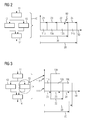
- a plant model 2 simulates an industrial plant 1.
- the plant model 2 comprises a plurality of submodels 11, 12, 13, 14, whereby only the submodel 11 is shown in this depiction of the modeling and for the sake of clarity.
- the system model 2 is always assigned at least one submodel 11.
- a connecting bar between the plant model 2 and the submodel 11 has an initialization 1,..., N, which means that the plant model can comprise 2 n submodels.
- plant model 2 comprises four submodels. Each submodel is associated with a behavioral description 11a, 12a, 13a, 14a.
- each submodel 11, 12, 13, 14 is assigned a visualization configuration 11b, 12b, 13b, 14b.
- each submodel 11, 12, 13, 14 is assigned a runtime model 11c, 12c, 13c, 14c.
- the plant model 2 is divided into several submodels 11, 12, 13, 14, the submodels 11, 12, 13, 14 being modulated with a behavioral description 11 a, 12 a, 13 a, 14 a.
- the behavioral descriptions are preferably in the form of calculation algorithms or mathematical equations.
- the runtime models 11c, 12c, 13c, 14c have a calculation time 21, 22, 23, 24 assigned to the respective submodel 11, 12, 13, 14.
- the model structure of the plant model 2 comprising the submodels 11, 12, 13, 14 is checked in an initialization phase of a computer system, the submodels in their execution order being the periods of the respective computation times 21, 22, 23, 24 Submodels 11,12,1,13,14 imaged in a superimposed representation.
- the calculation time 21, 22, 23, 24 of the partial models 11, 12, 13, 14 can thus be influenced by the situation, for this purpose, a parameter set 31, 32, 33, 34 is stored in the transit time models 11 c, 12 c, 13 c, 14 c.
- FIG. 2 Based on the plant model 2, a compilation run and a subsequent representation of the transit times of the submodels 11, 12, 13, 14 according to the prior art are shown.
- a translation run 40 is started by the initialization of the simulation.
- the plant model 2 is translated into an executable runtime model and optimizations are made.
- the translation run 40 the asset model 2 is translated into a form that can be executed by a computer system 101 on which the simulation will be executed, thereby additionally defining an execution order of the submodels 11, 12, 13, 14.
- the runtime models 11c, 12c, 13c, 14c are shown with their individual calculation times 21, 22, 23, 24.
- the first runtime model 11c takes a first calculation time 21
- the third runtime model 13c takes a third calculation time 23
- the second runtime model 12c takes a second calculation time 22
- the fourth runtime model 14c takes a fourth calculation time 24 in FIG Claim.
- the run-time models with their calculation times must lie within a simulation cycle time 30.
- the Calculation times 21, 23, 22, 24 over the simulation cycle time 30 results in a transit time violation, which is indicated by a runtime violation display 60.
- the second option is with FIG. 3 shown.
- the first submodel 11, the second submodel 12 and the fourth submodel 14 or in the illustration of their runtime models 11c, 12c, 14c are processed in a first run level 111 parallel to a second run level 112 for the third submodel 13 and the third runtime model 13c, respectively ,
- the first runtime level 111 is operated via a first computer system 101 with a first simulation software 101a
- the second runtime level 112 is operated in parallel via a second computer system 102 with a second simulation software 102a.
- the third partial model 13 is processed in parallel on another computer, since this is permissible by the execution order of the investment model 2.
- the total calculation time 20 is now below the required simulation cycle time 30 and is therefore real-time capable, the simulation is permitted and can be started.
- the first runtime model 11c according to FIG. 1 is configured with a first parameter set 31 and a first adaptation means 31a, wherein the adaptation means 31a includes, for example, program runtime functions such as "Get Runtime” or "Measure Runtime”. Due to the fact that the runtime models have the mentioned expansions, it is possible via a measuring means 108, which is part of a simulation arrangement 100 according to FIG. 5 is, on the submodels 11,12,13,14 and on the runtime models 11c, 12c, 13c, 14c, a time measurement are applied.
- runtime measurements 51, 52, 53, 54 are performed on the submodels 11, 12, 13, 14 during the simulation. From the runtime measurements 51, 52, 53, 54, configuration-dependent runtime forecasts for different computer configurations can be derived and a configuration data record of the computer configuration with the determined runtimes as Parameter set 31, 32, 33, 34 can be stored in the runtime models 11c, 12c, 13c, 14c.
- Each of the submodels 11, 12, 13, 14 with its associated runtime models 11 c, 12 c, 13 c, 14 c now has mechanisms, such as Get Runtime or Measure Runtime, which is indicated by a clock symbol in the submodels 11, 12, 13, 14 .
- a runtime variation 55 is indicated by hatching. This runtime variation 55 can occur during a simulation due to different workloads of the computer.
- a new third calculation time 23 'results for the third transit time model 13c, which in this case is notably smaller than the original calculation time 23.
- this runtime variation can only be determined if runtime measurements are carried out on the submodels 11, 12, 13, 14 during the simulation with the measuring device 108.
- the FIG. 5 1 shows a simulation arrangement 100 for simulating an automated industrial plant 1.
- the simulation arrangement 100 comprises a first computer system 101 with a first simulation software 101a.
- the simulation arrangement 100 further comprises a second computer system 102 with a second simulation software 102a.
- the second computer system 102 can be supplied with possible simulation data or models via an interface 110 of the first computer system 101.
- the first computer system 101 has a library 103.
- the submodels 11, 12, 13, 14 with their runtime models 11c, 12c, 13c, 14c are stored in the library 103.
- a component editor 104 is available; in the component editor 104, the industrial plant 1 is mapped onto the plant model 2 by means of links of the submodels 11, 12, 13, 14.
- the plant model 2 is supplied to a translation means 105 by a translation run application 40.
- the translation means 105 is configured to bring the plant model 2 into a form by a translation which is executable by the first computer system 101 with the first simulation software 101a for the simulation.
- a scheduling means 106 which is designed to define an execution order for the submodels 11, 12, 13, 14 in accordance with the combination of the submodels 11, 12, 13, 14, follows the translation means 105.
- the translation means 105 and the scheduling means 106 are data-coupled and connected to a monitoring means 107.
- the monitoring means 107 ensures that the runtime models 11c, 12c, 13c, 14c are mapped and represented graphically in the granularity of the calculation times of the partial models 11, 12, 13, 14, wherein the monitoring means 107 is further configured to detect a real-time violation and to locate.
- the measuring means 108 for measuring the transit times of each submodel 11, 12, 13, 14 during a simulation is further configured to display the measurement result for a currently valid computer configuration together with a configuration data record of the computer configuration of the first computer system 101 as parameter set 31,32,33,34 store. Since each submodel 11, 12, 13, 14 has an adaptation means 31 a, 32 a, 33 a, 34 a, adaptively adapted submodels 11 ', 12', 13 ', 14' can arise during the simulation, which can be used for later simulations with respect to their transit time behavior Depending on a computer configuration have been improved.
Abstract
Description
- Die Erfindung betrifft ein Verfahren zur Simulation einer automatisierten Industrieanlage, wobei die Industrieanlage in ein Anlagenmodell abgebildet wird und das Anlagenmodell in mehrere Teilmodelle aufgeteilt wird, die Teilmodelle werden dabei mit einer Verhaltensbeschreibung modeliert, welche einen Berechnungsalgorithmus oder eine mathematische Gleichung aufweisen, jedes Teilmodell wird gemäß der Abbildung der Industrieanlage in das Anlagenmodell mit mindestens einem anderen Teilmodell verschaltet, wobei in Vorbereitung zu der Simulation das Anlagenmodell bzw. die Teilmodelle durch einen Übersetzungslauf in eine Form übersetzt werden, welche von einem Computersystem, auf welchen die Simulation ausgeführt werden wird, ausgeführt werden kann, dabei wird zusätzlich eine Ausführungsreihenfolge der Teilmodelle festgelegt.
- Des Weiteren betrifft die Erfindung eine Simulationsanordnung zur Simulation einer automatisierten Industrieanlage, umfassend ein Computersystem mit einer Simulationssoftware, einer Bibliothek mit einer Mehrzahl von Teilmodellen, einem Komponenteneditor zur Erstellung eines Anlagenmodells für eine Industrieanlage, wobei die Industrieanlage mittels einer Verknüpfung der Teilmodelle auf das Anlagenmodell abbildbar ist, wobei die Teilmodelle einen Berechnungsalgorithmus oder eine mathematische Gleichung aufweisen, mit einem Übersetzungsmittel, welches ausgestaltet ist, das Anlagenmodell durch eine Übersetzung in eine Form zu bringen, welche von dem Computerprogramm, mit der Simulationssoftware für die Simulation, ausführbar ist, mit einem Disponentenmittel, welches ausgestaltet ist, gemäß der Verknüpfung der Teilmodelle eine Ausführungsreihenfolge für die Teilmodelle festzulegen.
- Beispielsweise bei einem Operator Training System (OTS) oder bei Systemen zur virtuellen Inbetriebnahme (VIBM) werden im Umfeld der Prozessindustrie vorzugsweise echtzeitfähige Simulationsmodelle eingesetzt. Im Sinne der Erfindung bedeutet Echtzeit oder Echtzeitfähigkeit, dass eine simulierte Zeiteinheit (Zeitscheibe) in der Dauer einer Abtastzeit eines Automatisierungsgerätes entspricht. Demnach versteht man unter Echtzeitbetrieb den Betrieb eines Rechnersystems, bei dem Programme zur Verarbeitung anfallender Daten ständig betriebsbereit sind, und zwar derart, dass die Verarbeitungsergebnisse innerhalb einer vorgegebenen Zeitspanne verfügbar sind.
- Aus dem Stand der Technik ist ein Simulationsverfahren und eine Simulationsanordnung aus dem Siemens-Benutzerhandbuch "SIMIT SCE", Ausgabestand Juli 2009, SIMIT-HB-SCE-2009-07, bekannt. Bei diesen bekannten Simulationsverfahren werden Anlagenmodelle für den Simulator erstellt, und beispielsweise über einen längeren Zeitraum ausgeführt. Bei einer Simulation der Anlagenmodelle über einen längeren Zeitraum kann es vorkommen, dass Laufzeitverletzungen auftreten, d.h. Laufzeiten der Modelle dauern länger, als ein vorgegebener Simulationszyklus, welcher wiederum einer realen Zeitdauer entspricht.
- Aufgabe der vorliegenden Erfindung ist es, spätere Laufzeitverletzungen für ein zu simulierendes Anlagenmodell während der Simulation zu vermeiden.
- Die Aufgabe wird für das Verfahren zur Simulation einer automatisierten Industrieanlage mit den Merkmalen des Oberbegriffes des unabhängigen Patentanspruches 1 dadurch gelöst, dass die Teilmodelle vor dem Übersetzungslauf jeweils um ein Laufzeitmodell erweitert werden, wobei die Laufzeitmodelle eine dem jeweiligen Teilmodell zugeordnete Berechnungszeit aufweisen, wobei anhand der Ausführungsreihenfolge und der um die Laufzeitmodelle erweiterten Teilmodelle eine Gesamtberechnungszeit des Anlagenmodells in der Granularität der Berechnungszeiten der Teilmodelle abgeleitet und grafische dargestellt wird, wodurch eine Erkennung und Lokalisierung von echtzeitkritischen Ablauffaden in dem Anlagenmodell möglich wird. Erfindungsgemäß wird eine Erweiterung von Simulationskomponenten, insbesondere von Teilmodellen, durch Laufzeitmodelle vorgesehen. In Abhängigkeit der Komplexität eines Teilmodells und der Leistung eines Rechners kann die Berechnungszeit für ein Teilmodell in einer simulierten Zeiteinheit schwanken und somit können auch Laufzeitverletzungen eintreten. Mithilfe der Erfindung ist vor dem Start einer Simulation sichergestellt, dass die Simulation in Echtzeit bzw. auf Basis der virtuellen Zeit ablauffähig ist und keine Laufzeitverletzungen auftreten.
- In einer vorteilhaften Ausgestaltung des Verfahrens wird die Berechnungszeit der Teilmodelle in Abhängigkeit von zumindest einem Parameter, welcher die Berechnungszeit während der Ausführung der Teilmodelle situationsbedingt beeinflusst, in den Laufzeitmodellen hinterlegt, wobei als der zumindest eine Parameter eine Rechnerkonfiguration des Computersystems gewählt wird. Mit einer Rechnerkonfiguration bezeichnet man eine bestimmte Anpassung von Programm- oder Hardwarebestandteilen eines Computersystems an die gegebene Infrastruktur, sowie das System seiner Zusammenstellung. Unter einer Hardware-Konfiguration versteht man eine bestimmte Zusammenstellung der Bauteile eines Computersystems. So besteht eine Hardwarekonfiguration z.B. aus einer bestimmten Hauptplatine, einem Prozessortyp, einer bestimmten Grafikkarte und einer bestimmten Festplatte. Darüber hinaus kann das Computersystem weiterhin so konfiguriert werden, dass es beispielsweise auf einen bestimmten Drucker druckt, in dem man einen bestimmten Drucker- oder Gerätetreiber installiert.
- Um eine zuverlässige Aussage über eine mögliche Laufzeitverletzung der Simulation zu erhalten, wird der Übersetzungslauf für das aus den Teilmodellen zusammengesetzte Anlagenmodell in einer Initialisierungsphase des Computersystems durchgeführt und die Teilmodelle in ihrer Ausführungsreihenfolge den Zeitdauern der jeweiligen Berechnungszeiten der Teilmodelle in einer überlagerten Darstellung abgebildet, wobei für den Fall, dass die Summe der Berechnungszeiten eine Zeitdauer einer Simulationszykluszeit überschreitet, ein Hinweis auf Echtzeitverletzung gegeben wird.
- Da ein Echtzeitsimulator in Zeitscheiben Zyklusweise die Teilmodelle neu berechnet, existiert als eine Echtzeitvorgabe eine geforderte Simulationszykluszeit. Dauert die Abarbeitung des Anlagenmodells in der Simulation länger als die geforderte Simulationszykluszeit, liegt eine Echtzeitverletzung vor. Eine Herausforderung bei der Modellierung einer prozesstechnischen Anlage ist es, eine geeignete Balance zwischen Detailierungsgrad und Simulationsgeschwindigkeit der Teilmodelle zu finden. Für den Fall, dass eine Bearbeitungszeit eines Teilmodells bereits außerhalb der geforderten Simulationszykluszeit liegt, wird das Verfahren dahingehend erweitert, dass die Zeitdauer der Simulationszykluszeit als überschritten erkannt wird, und zumindest ein Teilmodell parallel auf einen zweiten Computersystem abgearbeitet wird, damit die geforderte Simulationszykluszeit wieder eingehalten werden kann.
- In einer weiteren Optimierung des Verfahrens werden während einer Simulation Laufzeitmessungen an den Teilmodellen durchgeführt, wobei aus den Laufzeitmessungen konfigurationsabhängige Laufzeitvorhersagen für unterschiedliche Rechnerkonfigurationen abgeleitet werden und ein Konfigurationsdatensatz der Rechnerkonfiguration mit der ermittelten Laufzeit als Parametersatz in den Laufzeitmodellen abgespeichert wird. Hierdurch kann eine rechnerabhängige Laufzeit der Laufzeitmodelle für die Simulations-Modellierung sukzessive und adaptiv verbessert werden. Dabei werden während einer Simulation des Anlagenmodells ohne Echtzeitverletzungen kontinuierlich Laufzeitmessungen an den Teilmodellen durchgeführt und zusammen mit der gegenwärtigen Rechnerkonfiguration abgespeichert. Vorzugsweise werden "Worth Case" Laufzeiten, die primär für die Berechnung des Laufzeitmodells von Bedeutung sind, abgespeichert. Würden sich bei der Simulation die Laufzeiten so stark ändern, dass die Gefahr einer Echtzeitverletzung ansteigt, so könnte das oben genannte Verfahren zur Parallelisierung von Simulationsabläufen auf einen zweiten Computersystem erneut angewendet werden. Eine Umverteilung der Berechnungsreihenfolge würde die Gefahr der Echtzeitverletzung minimieren. Bei einer Modellierung einer neuen Anlage unter Verwendung der bereits bekannten Teilmodelle mit ihren Laufzeitmodellen kann auf die Erfahrung des Laufzeitverhaltens aus der Vergangenheit zurückgegriffen werden. Damit verbessert sich eine Anlagensimulation evolutionär mit jedem neuen Einsatz.
- Die eingangs genannte Aufgabe wird ebenfalls durch eine Simulationsanordnung zur Simulation einer automatisierten Industrieanlage mit den Merkmalen des Oberbegriffes des unabhängigen Patentanspruches 6 dadurch gelöst, dass die Teilmodelle weiterhin ein Laufzeitmodell aufweisen, wobei die Laufzeitmodelle eine dem jeweiligen Teilmodell zugeordnete Berechnungszeit aufweisen, wobei das Übersetzungsmittel weiterhin dazu ausgestaltet ist, anhand der Ausführungsreihenfolge und der um die Laufzeitmodelle erweiterten Teilmodelle eine Gesamtberechnungszeit des Anlagenmodells in einer Granularität der Berechnungszeiten der Teilmodelle abzuleiten und grafisch darzustellen, wodurch eine Erkennung und Lokalisierung von echtzeitkritischen Ablauffaden in dem Anlagenmodell möglich wird.
- Vorteilhafter Weise weisen die Laufzeitmodelle ein Anpassungsmittel auf, und das Anpassungsmittel ist dazu ausgestaltet, die Berechnungszeit der Teilmodelle in Abhängigkeit von zumindest einem Parameter, welcher die Berechnungszeit während der Ausführung der Teilmodelle situationsbedingt beeinflusst, dynamisch anzupassen, wobei als der zumindest eine Parameter eine Rechnerkonfiguration des Computersystems gewählt wird.
- In einer weiteren optimierten Ausführung der Simulationsanordnung besitzt diese ein Überwachungsmittel, welches ausgestaltet ist, die Teilmodelle in der Ausführungsreihenfolge den Zeitdauern der jeweiligen Berechnungszeiten der Teilmodelle in einer überlagerten Darstellung abzubilden, und ist weiterhin dazu ausgestaltet, für den Fall, dass die Summe der Berechnungszeiten eine Zeitdauer einer Simulationszykluszeit überschreitet, einen Hinweis auf eine Echtzeitverletzung auszugeben.
- Für ein Parallelisieren einer Simulation, d.h. die Teilmodelle auf unterschiedlichen Simulatoren (Rechnern) abzuarbeiten, ist die Simulationsanordnung ausgestaltet mit einer Schnittstelle zu einem zweiten Computersystem mit einer zweiten Simulationssoftware, weiterhin ausgestaltet, ein Teilmodell zur parallelen Abarbeitung an das zweite Computersystem zu übergeben.
- Eine weiter verbesserte Simulationsanordnung ist ausgestaltet, mit einem Messmittel zur Messung der Laufzeit eines Teilmodells während einer Simulation. Weiterhin ist die Simulationsanordnung ausgestaltet, das Messergebnis für eine derzeit gültige Rechnerkonfiguration zusammen mit einem Konfigurationsdatensatz der Rechnerkonfiguration des Computersystems als Parametersatz in den Laufzeitmodellen abzuspeichern.
- Zur weiteren Erläuterung des Verfahrens und der Simulationsanordnung zeigt die Zeichnung ein Ausführungsbeispiel. Es zeigt
- FIG 1
- ein um ein Laufzeitmodell erweitertes Teilmodell in einem Anlagenmodell,
- FIG 2
- ein Anlagenmodell und die Darstellung der Teillaufzeiten,
- FIG 3
- das Anlagenmodell aus
FIG 2 und eine Darstellung der Teillaufzeiten bei einer Parallelverarbeitung, - FIG 4
- das Anlagenmodell mit den Umlaufzeitmodelle erweiterten Teilmodelle und die Darstellung der Teillaufzeiten unter Einhaltung einer geforderten Simulationszykluszeit, und
- FIG 5
- eine Simulationsanordnung zur Simulation einer automatisierten Industrieanlage.
- Gemäß der
FIG 1 bildet ein Anlagenmodell 2 eine Industrieanlage 1 nach. Das Anlagenmodell 2 umfasst mehrere Teilmodelle 11,12,13,14, wobei bei dieser Darstellung der Modellierung und der Übersichtlichkeit halber nur das Teilmodell 11 dargestellt ist. Dem Anlagenmodell 2 ist immer zumindest ein Teilmodell 11 zugeordnet. Ein Verbindungsstrich zwischen dem Anlagenmodell 2 und dem Teilmodell 11 weist eine Initialisierung 1,...,n auf, welches bedeutet, dass das Anlagenmodell 2 n-Teilmodelle umfassen kann. In unserem Beispiel umfasst das Anlagenmodell 2 vier Teilmodelle. Jedem Teilmodell ist eine Verhaltensbeschreibung 11a,12a,13a,14a zugeordnet. Für eine spätere Visualisierung des Anlagenmodells 2 ist jedem Teilmodell 11,12,13,14 eine Visualisierungskonfiguration 11b,12b, 13b,14b zugeordnet. Zur besseren Erkennung und Lokalisierung von echtzeitkritischen Pfaden in einem Anlagenmodell, ist jedem Teilmodell 11,12,13,14 ein Laufzeitmodell 11c,12c,13c,14c zugeordnet. Demnach wird das Anlagenmodell 2 in mehrere Teilmodelle 11,12,13,14 aufgeteilt, wobei die Teilmodelle 11,12, 13,14 mit einer Verhaltensbeschreibung 11a,12a,13a,14a moduliert werden. Die Verhaltensbeschreibungen liegen vorzugsweise in Form von Berechnungsalgorithmen oder mathematischen Gleichungen vor. Die Laufzeitmodelle 11c,12c,13c,14c weisen eine dem jeweiligen Teilmodell 11,12,13,14 zugeordnete Berechnungszeit 21,22,23,24 auf. Bei einem Übersetzungslauf für eine spätere Simulation wird die Modellstruktur des Anlagenmodells 2 umfassend die Teilmodelle 11,12,13,14 in einer Initialisierungsphase eines Computersystems überprüft, dabei werden die Teilmodelle in ihrer Ausführungsreihenfolge den Zeitdauern der jeweiligen Berechnungszeiten 21,22,23,24 der Teilmodelle 11,12,1,13,14 in einer überlagerten Darstellung abgebildet. - Mit der überlagerten Darstellung ist nun eine Gesamtberechnungszeit 20 des Anlagenmodells 2 in der Granularität der Berechnungszeiten 21,22,23,24 erkennbar, wodurch eine Erkennung und Lokalisierung von echtzeitkritischen Ablaufpfaden in dem Anlagenmodell 2 möglich wird.
- Die Berechnungszeit 21,22,23,24 der Teilmodelle 11,12,13,14 kann so situationsbedingt beeinflusst werden, hierzu wird in den Laufzeitmodellen 11c,12c,13c,14c ein Parametersatz 31,32,33,34 hinterlegt.
- Gemäß
FIG 2 ist ausgehend von dem Anlagenmodell 2 ein Übersetzungslauf und eine anschließende Darstellung der Laufzeiten der Teilmodelle 11,12,13,14 nach dem Stand der Technik dargestellt. Bei einer Initialisierung der Simulation, wie z.B. bei einem Anlagensimulator nach dem Stand der Technik "SIMIT" wird durch die Initialisierung der Simulation ein Übersetzungslauf 40 gestartet. Hierbei wird das Anlagenmodell 2 in ein ausführbares Laufzeitmodell übersetzt und Optimierungen werden vorgenommen. Durch den Übersetzungslauf 40 wird das Anlagenmodell 2 in eine Form übersetzt, welche von einem Computersystem 101, auf welchem die Simulation ausgeführt werden wird, ausgeführt werden kann, dabei wird zusätzlich eine Ausführungsreihenfolge der Teilmodelle 11,12,13,14 festgelegt. - Über einer Zeitachse 50 sind die Laufzeitmodelle 11c,12c,13c, 14c mit ihren einzelnen Berechnungszeiten 21,22,23,24 dargestellt. Auf der Zeitachse 50 nimmt das erste Laufzeitmodell 11c eine erste Berechnungszeit 21 in Anspruch, das dritte Laufzeitmodell 13c nimmt eine dritte Berechnungszeit 23 in Anspruch, das zweite Laufzeitmodell 12c nimmt eine zweite Berechnungszeit 22 in Anspruch und das vierte Laufzeitmodell 14c nimmt eine vierte Berechnungszeit 24 in Anspruch.
- Aus der Summe der Berechnungszeiten 21,23,22,24 ergibt sich eine Gesamtberechnungszeit 20.
- Um eine echtzeitfähige Simulation zu erhalten, müssen die Laufzeitmodelle mit ihren Berechnungszeiten aber innerhalb einer Simulationszykluszeit 30 liegen. Mit Überschreiten der Berechnungszeiten 21,23,22,24 über die Simulationszykluszeit 30 entsteht eine Laufzeitverletzung, welches durch eine Laufzeitverletzungsanzeige 60 angezeigt wird.
- Gemäß
FIG 3 ist eine Möglichkeit dargestellt, bei welcher eine neue Gesamtberechnungszeit 20 innerhalb der geforderten Simulationszykluszeit 30 liegt. Hingegen ist gemäß derFIG 2 in der geforderten Simulationszykluszeit beispielsweise die Berechnung des Teilmodells 12 nur teilweise erfolgt und mit dem Teilmodell 14 wurde mit der Berechnung noch gar nicht begonnen. D.h. das Anlagenmodell 2 kann z.B. nicht für einen HIL-Test mit realen Steuerungen oder für ein Operator Training System eingesetzt werden. Durch die vorliegende Erfindung wird bereits vor der Ausführung der eigentlichen Simulation eine Kenntnis darüber erlangt, ob eine Laufzeitverletzung vorliegt. Nach dem bisherigen Stand der Technik würden solche Echtzeitverletzungen oder Laufzeitverletzungen erst während einer Simulation zu Problemen führen und auch erst dann erkannt werden können. Da eine Worst Case Laufzeit eines Anlagenmodells 2 bzw. eines Simulationsmodells von den Eingabewerten abhängig ist, kann eine Echtzeitverletzung nicht nur zu Beginn der Simulation, sondern auch zu jedem anderen beliebigen Zeitpunkt auftreten. Da für ausführliche Tests oder Schulungen oftmals sehr lange Simulationen durchgeführt werden, ist es von zentraler Bedeutung, Echtzeitverletzungen schon vor der eigentlichen Simulation, z.B. wie hier beschrieben, bei der Initialisierung kurz nach dem Übersetzungslauf, zu erkennen und eventuell beheben zu können. Ist eine Echtzeitverletzung erkannt worden, können Gegenmaßnahmen ergriffen werden. Hierzu gibt es zwei Möglichkeiten: - 1. Die Teilmodelle vereinfachen, d.h. durch einen höheren Abstraktionsgrad die Berechnungszeit des Teilmodells verringern,
- 2. Die Simulation parallelisieren, d.h. die Teilmodelle auf unterschiedlichen Simulatoren abarbeiten.
- Die zweite Möglichkeit ist mit
FIG 3 dargestellt. Das erste Teilmodell 11, das zweite Teilmodell 12 und das vierte Teilmodell 14 bzw. in der Abbildung ihrer Laufzeitmodelle 11c,12c,14c werden in einer ersten Ablaufebene 111 parallel zu einer zweiten Ablaufebene 112 für das dritte Teilmodell 13 bzw. das dritte Laufzeitmodell 13c abgearbeitet. Die erste Laufzeitebene 111 wird über ein erstes Computersystem 101 mit einer ersten Simulationssoftware 101a bedient, die zweite Ablaufebene 112 wird über ein zweites Computersystem 102 mit einer zweiten Simulationssoftware 102a parallel bedient. - Demnach wird auf einem anderen Rechner das dritte Teilmodell 13 parallel abgearbeitet, da dies durch die Ausführungsreihenfolge des Anlagemodells 2 zulässig ist. Die Gesamtberechnungszeit 20 liegt nun unterhalb der geforderten Simulationszykluszeit 30 und ist somit echtzeitfähig, die Simulation ist zulässig und kann begonnen werden.
- Mit der
FIG 4 ist ein Simulationsablauf bzw. ein Übersetzungslauf und eine Abbildung der Laufzeitmodelle 11c,12c,13c, 14c mit ihren Berechnungszeiten in einem optimierten Simulationsmodell gemäß der Erfindung dargestellt. Das erste Laufzeitmodell 11c gemäßFIG 1 mit einem ersten Parametersatz 31 und einem ersten Anpassungsmittel 31a ausgestaltet ist, wobei das Anpassungsmittel 31a z.B. programmtechnische Laufzeitfunktionen wie "Get Runtime" oder "Measure Runtime" beinhaltet. Dadurch, dass die Laufzeitmodelle die genannten Erweiterungen aufweisen, kann über ein Messmittel 108, welches Bestandteil einer Simulationsanordnung 100 gemäßFIG 5 ist, auf die Teilmodelle 11,12,13,14 bzw. auf die Laufzeitmodelle 11c,12c,13c,14c eine Zeitmessung angewendet werden. Um dem Problem einer Echtzeitverletzung während einer Simulation vorzubeugen werden während der Simulation Laufzeitmessungen 51,52,53,54 an den Teilmodellen 11,12,13,14 durchgeführt. Aus den Laufzeitmessungen 51,52,53,54 können konfigurationsabhängige Laufzeitvorhersagen für unterschiedliche Rechnerkonfigurationen abgeleitet werden und ein Konfigurationsdatensatz der Rechnerkonfiguration mit den ermittelten Laufzeiten als Parametersatz 31,32,33,34 können in den Laufzeitmodellen 11c,12c,13c,14c abgespeichert werden. - Würden sich nun bei der Simulation die Laufzeiten bzw. die Berechnungszeiten 21,22,23,24 so stark ändern, dass die Gefahr einer Echtzeitverletzung ansteigt, so könnte das bereits in
FIG 3 erwähnte Verfahren der Parallelisierung vorgenommen werden. Eine Umverteilung der Berechnungsreihenfolge würde die Gefahr der Echtzeitverletzung minimieren. Diese Verfahren der Umverteilung der Berechnungsreihenfolge während der Simulation bringen einen entscheidenden Vorteil um einer Echtzeitverletzung vorzubeugen. Bei einer Modellierung einer neuen Anlage unter Verwendung der bekannten Teilmodelle 11,12, 13,14 kann auf die Erfahrung des Laufzeitverhaltens aus der Vergangenheit zurückgegriffen werden. Damit verbessert sich die Anlagensimulation evolutionär mit jedem neuen Einsatz. - Jedes der Teilmodelle 11,12,13,14 mit seinen zugehörigen Laufzeitmodellen 11c,12c,13c,14c weist nun Mechanismen auf, wie beispielsweise Get Runtime oder Measure Runtime, welches durch ein Uhrensymbol in den Teilmodellen 11,12,13,14 angedeutet ist. In dem Laufzeitmodell 13c ist schraffiert eine Laufzeitschwankung 55 angedeutet. Diese Laufzeitschwankung 55 kann während einer Simulation durch unterschiedliche Auslastungen des Rechners auftreten. Mit der Laufzeitschwankung 55 ergibt sich für das dritte Laufzeitmodell 13c eine neue dritte Berechnungszeit 23', welche in diesem Fall glücklicherweise kleiner als die ursprüngliche Berechnungszeit 23 ist. Diese Laufzeitschwankung kann aber nur ermittelt werden, wenn während der Simulation mit dem Messmittel 108 Laufzeitmessungen an den Teilmodellen 11,12,13,14 vorgenommen werden.
- Die
FIG 5 zeigt eine Simulationsanordnung 100 zur Simulation einer automatisierten Industrieanlage 1. Die Simulationsanordnung 100 umfasst ein erstes Computersystem 101 mit einer ersten Simulationssoftware 101a. Für eine optionale parallele Simulation umfasst die Simulationsanordnung 100 weiterhin ein zweites Computersystem 102 mit einer zweiten Simulationssoftware 102a. Das zweite Computersystem 102 kann über eine Schnittstelle 110 des ersten Computersystems 101 mit möglichen Simulationsdaten oder Modellen versorgt werden. Weiterhin weist das erste Computersystem 101 eine Bibliothek 103 auf. In der Bibliothek 103 sind die Teilmodelle 11,12,13,14 mit ihren Laufzeitmodellen 11c,12c,13c,14c abgelegt. Zur Erstellung eines Anlagenmodells 2 steht ein Komponenteneditor 104 zur Verfügung, in dem Komponenteneditor 104 wird die Industrieanlage 1 mittels Verknüpfungen der Teilmodelle 11,12,13,14 auf das Anlagenmodell 2 abgebildet. - Das Anlagenmodell 2 wird durch eine Übersetzungslaufanwendung 40 einem Übersetzungsmittel 105 zugeführt. Das Übersetzungsmittel 105 ist ausgestaltet, das Anlagenmodell 2 durch eine Übersetzung in eine Form zu bringen, welche von dem ersten Computersystem 101, mit der ersten Simulationssoftware 101a für die Simulation, ausführbar ist.
- Ein Disponentenmittel 106, welches ausgestaltet ist gemäß der Verknüpfung der Teilmodelle 11,12,13,14 eine Ausführungsreihenfolge für die Teilmodelle 11,12,13,14 festzulegen, schließt sich an das Übersetzungsmittel 105 an.
- Das Übersetzungsmittel 105 und das Disponentenmittel 106 sind datentechnisch gekoppelt und mit einem Überwachungsmittel 107 verbunden. Das Überwachungsmittel 107 sorgt dafür, dass die Laufzeitmodelle 11c,12c,13c,14c in der Granularität der Berechnungszeiten der Teilmodelle 11,12,13,14 abgebildet und grafisch dargestellt werden, wobei das Überwachungsmittel 107 weiterhin dazu ausgestaltet ist, eine Echtzeitverletzung zu erkennen und zu lokalisieren.
- Das Messmittel 108 zur Messung der Laufzeiten eines jeden Teilmodells 11,12,13,14 während einer Simulation ist weiterhin dazu ausgestaltet, das Messergebnis für eine derzeit gültige Rechnerkonfiguration zusammen mit einem Konfigurationsdatensatz der Rechnerkonfiguration des ersten Computersystems 101 als Parametersatz 31,32,33,34 abzuspeichern. Da jedes Teilmodell 11,12,13,14 je ein Anpassungsmittel 31a,32a,33a, 34a aufweist, können adaptiv angepasste Teilmodelle 11',12', 13',14' während der Simulation entstehen, welche für spätere Simulationen bezüglich ihres Laufzeitverhaltens in Abhängigkeit von einer Rechnerkonfiguration verbessert worden sind.
Claims (10)
- Verfahren zur Simulation einer automatisierten Industrieanlage (1), wobei die Industrieanlage (1) in ein Anlagenmodell (2) abgebildet wird und das Anlagenmodell (2) in mehrere Teilmodelle (11,12,13,14) aufgeteilt wird, die Teilmodelle (11,12,13,14) werden dabei mit einer Verhaltensbeschreibung (11a,12a,13a,14a) modelliert, welche einen Berechnungsalgorithmus oder eine mathematische Gleichung aufweisen, jedes Teilmodell (11,12,13,14) wird gemäß der Abbildung der Industrieanlage (1) in das Anlagenmodell (2) mit mindestens einem anderen Teilmodell (11,12,13,14) verschaltet, wobei in Vorbereitung zu der Simulation das Anlagenmodell (2) bzw. die Teilmodelle (11,12,13,14) durch einen Übersetzungslauf in eine Form übersetzt werden, welche von einem Computersystem (101), auf welchen die Simulation ausgeführt werden wird, ausgeführt werden kann, dabei wird zusätzlich eine Ausführungsreihenfolge der Teilmodelle (11,12,13,14) festgelegt, dadurch gekennzeichnet, dass die Teilmodelle (11,12,13,14) vor dem Übersetzungslauf jeweils um ein Laufzeitmodell (11c,12c,13c,14c) erweitert werden, wobei die Laufzeitmodelle (11c,12c,13c,14c) eine dem jeweiligen Teilmodell (11,12,13,14) zugeordnete Berechnungszeit (21,22,23,24) aufweisen, wobei anhand der Ausführungsreihenfolge und der um die Laufzeitmodelle (11c,12c,13c,14c) erweiterten Teilmodelle (11,12,13,14) eine Gesamtberechnungszeit (20) des Anlagenmodells (2) in der Granularität der Berechnungszeiten der Teilmodelle (11,12,13,14) abgeleitet und grafisch dargestellt wird, wodurch eine Erkennung und Lokalisierung von echtzeitkritischen Ablaufpfaden in dem Anlagenmodell (2) möglich wird.
- Verfahren nach Anspruch 1, wobei die Berechnungszeit (21, 22,23,24) der Teilmodelle in Abhängigkeit von zumindest einem Parameter (31,32,33,34), welcher die Berechnungszeit während der Ausführung der Teilmodelle (11,12,13,14) situationsbedingt beeinflusst, in den Laufzeitmodellen (11c,12c,13c,14c) hinterlegt wird, wobei als der zumindest eine Parameter eine Rechnerkonfiguration des Computersystems (101) gewählt wird.
- Verfahren nach Anspruch 1 oder 2, wobei der Übersetzungslauf für das aus den Teilmodellen (11,12,13,14) zusammengesetzte Anlagenmodell (2) in einer Initialisierungsphase des Computersystems (101) durchgeführt wird und die Teilmodelle (11,12,13,14) in ihrer Ausführungsreihenfolge den Zeitdauern der jeweiligen Berechnungszeiten (21,22,23,24) der Teilmodelle (11,12,13,14) in einer überlagerten Darstellung abgebildet werden, wobei für den Fall, dass die Summe der Berechnungszeiten (21,22,23,24) eine Zeitdauer einer Simulationszykluszeit (30) überschreitet, ein Hinweis auf eine Echtzeitverletzung gegeben wird.
- Verfahren nach Anspruch 3, wobei für den Fall, dass die Zeitdauer der Simulationszykluszeit (30) überschritten wird, wird zumindest ein Teilmodell (11,12,13,14) parallel auf einem zweiten Computersystem (102) abgearbeitet.
- Verfahren nach einem der Ansprüche 2 bis 4, wobei während einer Simulation Laufzeitmessungen (51,52,53,54) an den Teilmodellen (11,12,13,14) durchgeführt werden, wobei aus den Laufzeitmessungen (51,52,53,54) konfigurationsabhängige Laufzeitvorhersagen für unterschiedliche Rechnerkonfigurationen abgeleitet werden und ein Konfigurationsdatensatz der Rechnerkonfiguration mit der ermittelten Laufzeit als Parametersatz (31,32,33,34) in den Laufzeitmodellen (11c,12c,13c,14c) abgespeichert wird.
- Simulationsanordnung (100) zur Simulation einer automatisierten Industrieanlage (1), umfassend- ein Computersystem (101) mit- einer Simulationssoftware(101a),- einer Bibliothek (103) mit einer Mehrzahl von Teilmodellen (11,12,13,14),- einem Komponenteneditor (104) zur Erstellung eines Anlagenmodells (2) für eine Industrieanlage (1), wobei die Industrieanlage (1) mittels einer Verknüpfung der Teilmodelle (11,12,13,14) auf das Anlagenmodell (2) abbildbar ist, wobei die Teilmodelle (11,12,13,14) einen Berechnungsalgorithmus (21,22,23,24) oder eine mathematische Gleichung aufweisen, mit- einem Übersetzungsmittel (105), welches ausgestaltet ist, das Anlagenmodell (2) durch eine Übersetzung in eine Form zu bringen, welche von dem Computersystem (101) mit der Simulationssoftware (101a) für die Simulation ausführbar ist, mit- einem Disponentenmittel (106), welches ausgestaltet ist gemäß der Verknüpfung der Teilmodelle (11,12,13,14) eine Ausführungsreihenfolge für die Teilmodelle (11,12,13,14) festzulegen,dadurch gekennzeichnet, dass die Teilmodelle (11,12,13,14) weiterhin ein Laufzeitmodell (11c,12c,-13c,14c) aufweisen, wobei die Laufzeitmodelle (11c,12c,13c,-14c) eine dem jeweiligen Teilmodell (11,12,13,14) zugeordnete Berechnungszeit (21,22,23,24) aufweisen, wobei das Übersetzungsmittel (105) weiterhin dazu ausgestaltet ist anhand der Ausführungsreihenfolge und der um die Laufzeitmodelle (11c,12c,13c,14) erweiterten Teilmodelle (11,12,13,14) eine Gesamtberechnungszeit (20) des Anlagenmodells(2) in der Granularität der Berechnungszeiten (21,22,23,24) der Teilmodelle (11,12,13,14) abzuleiten und grafisch darzustellen, wodurch eine Erkennung und Lokalisierung von echtzeitkritischen Ablaufpfaden in dem Anlagenmodell (2) möglich wird.
- Simulationsanordnung (100) nach Anspruch 6, wobei die Laufzeitmodelle (11c,12c,13c,14c) ein Anpassungsmittel (31a,-32a,33a,34a) aufweisen und das Anpassungsmittel (31a,32a,-33a,34a) dazu ausgestaltet ist die Berechnungszeit (21,22,-23,24) der Teilmodelle (11,12,13,14) in Abhängigkeit von zumindest einem Parameter (31,32,33,34), welcher die Berechnungszeit (21,22,23,24) während der Ausführung der Teilmodelle (11,12,13,14) situationsbedingt beeinflusst, dynamisch anzupassen, wobei als der zumindest eine Parameter eine Rechnerkonfiguration des Computersystems (101) gewählt wird.
- Simulationsanordnung (100) nach einem der Ansprüche 6 oder 7, mit einem Überwachungsmittel (107), welches ausgestaltet ist, die Teilmodelle (11,12,13,14) in der Ausführungsreihenfolge den Zeitdauern der jeweiligen Berechnungszeiten (21,22,23,24) der Teilmodelle (11,12,13,14) in einer überlagerten Darstellung abzubilden, und weiter dazu ausgestaltet ist, für den Fall, dass die Summe der Berechnungszeiten (21,22,23,24) eine Zeitdauer einer Simulationszykluszeit (30) überschreitet ein Hinweis auf eine Echtzeitverletzung ausgegeben wird.
- Simulationsanordnung (100) nach einem der Ansprüche 6 bis 8, ausgestaltet mit einer Schnittstelle (110) zu einem zweiten Computersystem (102) mit einer zweiten Simulationssoftware (102a), weiterhin ausgestaltet ein Teilmodell (11,12,13, 14) zur parallelen Abarbeitung an das zweite Computersystem (102) zu übergeben.
- Simulationsanordnung (100) nach einem der Ansprüche 6 bis 9, ausgestaltet mit einem Messmittel (108) zur Messung der Laufzeit eines Teilmodells (11,12,13,14) während einer Simulation, weiterhin ausgestaltet das Messergebnis für eine derzeit gültige Rechnerkonfiguration zusammen mit einem Konfigurationsdatensatz der Rechnerkonfiguration des Computersystems (101) als Parametersetz (31,32,33,34) in den Laufzeitmodellen (11c,12c,13c,14c) abzuspeichern.
Priority Applications (3)
| Application Number | Priority Date | Filing Date | Title |
|---|---|---|---|
| EP14151926.4A EP2897011B1 (de) | 2014-01-21 | 2014-01-21 | Verfahren und Simulationsanordnung zur Simulation einer automatisierten Industrieanlage |
| US14/600,725 US10108763B2 (en) | 2014-01-21 | 2015-01-20 | Method and simulation arrangement for simulating an automated industrial plant |
| CN201510028069.XA CN104793983B (zh) | 2014-01-21 | 2015-01-20 | 用于模拟自动化工业设备的方法和模拟装置 |
Applications Claiming Priority (1)
| Application Number | Priority Date | Filing Date | Title |
|---|---|---|---|
| EP14151926.4A EP2897011B1 (de) | 2014-01-21 | 2014-01-21 | Verfahren und Simulationsanordnung zur Simulation einer automatisierten Industrieanlage |
Publications (2)
| Publication Number | Publication Date |
|---|---|
| EP2897011A1 true EP2897011A1 (de) | 2015-07-22 |
| EP2897011B1 EP2897011B1 (de) | 2019-08-21 |
Family
ID=49989563
Family Applications (1)
| Application Number | Title | Priority Date | Filing Date |
|---|---|---|---|
| EP14151926.4A Active EP2897011B1 (de) | 2014-01-21 | 2014-01-21 | Verfahren und Simulationsanordnung zur Simulation einer automatisierten Industrieanlage |
Country Status (3)
| Country | Link |
|---|---|
| US (1) | US10108763B2 (de) |
| EP (1) | EP2897011B1 (de) |
| CN (1) | CN104793983B (de) |
Cited By (3)
| Publication number | Priority date | Publication date | Assignee | Title |
|---|---|---|---|---|
| CN108958198A (zh) * | 2018-07-27 | 2018-12-07 | 北京航天云路有限公司 | 三维智能产线模拟同步方法及系统 |
| WO2021052955A1 (de) * | 2019-09-19 | 2021-03-25 | Siemens Energy Global GmbH & Co. KG | System und verfahren zum bereitstellen einer digitalen nachbildung einer anlage und entsprechendes computerprogrammprodukt |
| CN113591281A (zh) * | 2021-07-13 | 2021-11-02 | 苏州同元软控信息技术有限公司 | modelica模型计算方法、装置、设备和存储介质 |
Families Citing this family (6)
| Publication number | Priority date | Publication date | Assignee | Title |
|---|---|---|---|---|
| US11972177B2 (en) * | 2013-11-08 | 2024-04-30 | Rockwell Automation Technologies, Inc. | Interface for data exchange between industrial controllers and simulation applications for simulating a machine |
| US10755003B2 (en) | 2013-11-08 | 2020-08-25 | Rockwell Automation Technologies, Inc. | Time synchronization of signal transmission intervals for simulating a machine in industrial automation |
| EP3141970B1 (de) * | 2015-09-09 | 2017-11-15 | Siemens Aktiengesellschaft | Dezentrale peripherie |
| CN109624108B (zh) * | 2018-11-16 | 2020-07-24 | 银川隆基硅材料有限公司 | 一种模拟硅片切片机生产时间的方法与设备 |
| EP3796117B1 (de) * | 2019-09-18 | 2021-10-27 | Siemens Aktiengesellschaft | Diagnoseverfahren und diagnosesystem für eine verfahrenstechnische anlage |
| CN113591280B (zh) * | 2021-07-13 | 2023-08-22 | 苏州同元软控信息技术有限公司 | modelica模型计算方法、装置、设备和存储介质 |
Citations (2)
| Publication number | Priority date | Publication date | Assignee | Title |
|---|---|---|---|---|
| WO2011023204A1 (en) * | 2009-08-24 | 2011-03-03 | Abb Research Ltd. | Simulation of distributed virtual control systems |
| DE102011055657A1 (de) * | 2011-11-23 | 2013-05-23 | Schneider Electric Automation Gmbh | Verfahren, System und Computer-Programm-Produkt zur Simulation eines Produktions-Automatisierungssystems mit service-orientierter Architektur |
Family Cites Families (7)
| Publication number | Priority date | Publication date | Assignee | Title |
|---|---|---|---|---|
| CA2617981A1 (en) * | 2005-08-05 | 2007-02-15 | Pfizer Products Inc. | Automated batch manufacturing |
| ATE488793T1 (de) * | 2006-09-11 | 2010-12-15 | Dspace Gmbh | Verfahren zum test eines elektronischen steuerungssystems |
| DE102006061796A1 (de) * | 2006-12-21 | 2008-06-26 | Dspace Digital Signal Processing And Control Engineering Gmbh | Verfahren und Vorrichtung zur dynamischen Behandlung von Objekten |
| US20090089029A1 (en) * | 2007-09-28 | 2009-04-02 | Rockwell Automation Technologies, Inc. | Enhanced execution speed to improve simulation performance |
| CN106508012B (zh) * | 2010-04-16 | 2013-07-24 | 中国人民解放军国防科学技术大学 | 面向服务的群体行为并行仿真方法 |
| WO2011149553A1 (en) * | 2010-05-27 | 2011-12-01 | The Mathworks, Inc. | Partitioning block diagrams into executable contextual models |
| CN102567856A (zh) * | 2012-01-16 | 2012-07-11 | 浪潮集团山东通用软件有限公司 | 一种工作流系统中实现时间管理的方法 |
-
2014
- 2014-01-21 EP EP14151926.4A patent/EP2897011B1/de active Active
-
2015
- 2015-01-20 US US14/600,725 patent/US10108763B2/en active Active
- 2015-01-20 CN CN201510028069.XA patent/CN104793983B/zh active Active
Patent Citations (2)
| Publication number | Priority date | Publication date | Assignee | Title |
|---|---|---|---|---|
| WO2011023204A1 (en) * | 2009-08-24 | 2011-03-03 | Abb Research Ltd. | Simulation of distributed virtual control systems |
| DE102011055657A1 (de) * | 2011-11-23 | 2013-05-23 | Schneider Electric Automation Gmbh | Verfahren, System und Computer-Programm-Produkt zur Simulation eines Produktions-Automatisierungssystems mit service-orientierter Architektur |
Non-Patent Citations (3)
| Title |
|---|
| GUILLERMO VIGUERAS ET AL: "Workload balancing in distributed crowd simulations: the partitioning method", THE JOURNAL OF SUPERCOMPUTING, vol. 58, no. 2, 19 December 2009 (2009-12-19), pages 261 - 269, XP055121688, ISSN: 0920-8542, DOI: 10.1007/s11227-009-0375-5 * |
| PAPAZOGLOU M P ET AL: "Service-oriented computing", COMMUNICATIONS OF THE ACM, ASSOCIATION FOR COMPUTING MACHINERY, INC, UNITED STATES, vol. 46, no. 10, 1 October 2003 (2003-10-01), pages 25 - 28, XP002497726, ISSN: 0001-0782, DOI: 10.1145/944217.944233 * |
| WOOK HYUN KWON ET AL: "Real-time distributed software-in-the-loop simulation for distributed control systems", COMPUTER AIDED CONTROL SYSTEM DESIGN, 1999. PROCEEDINGS OF THE 1999 IE EE INTERNATIONAL SYMPOSIUM ON KOHALA COAST, HI, USA 22-27 AUG. 1999, PISCATAWAY, NJ, USA,IEEE, US, 22 August 1999 (1999-08-22), pages 115 - 119, XP010360421, ISBN: 978-0-7803-5500-2 * |
Cited By (6)
| Publication number | Priority date | Publication date | Assignee | Title |
|---|---|---|---|---|
| CN108958198A (zh) * | 2018-07-27 | 2018-12-07 | 北京航天云路有限公司 | 三维智能产线模拟同步方法及系统 |
| CN108958198B (zh) * | 2018-07-27 | 2021-05-04 | 北京航天云路有限公司 | 三维智能产线模拟同步方法及系统 |
| WO2021052955A1 (de) * | 2019-09-19 | 2021-03-25 | Siemens Energy Global GmbH & Co. KG | System und verfahren zum bereitstellen einer digitalen nachbildung einer anlage und entsprechendes computerprogrammprodukt |
| CN114424132A (zh) * | 2019-09-19 | 2022-04-29 | 西门子能源环球有限责任两合公司 | 用于提供设施的数字复制品的系统和方法和对应的计算机程序产品 |
| CN113591281A (zh) * | 2021-07-13 | 2021-11-02 | 苏州同元软控信息技术有限公司 | modelica模型计算方法、装置、设备和存储介质 |
| CN113591281B (zh) * | 2021-07-13 | 2023-08-29 | 苏州同元软控信息技术有限公司 | modelica模型计算方法、装置、设备和存储介质 |
Also Published As
| Publication number | Publication date |
|---|---|
| CN104793983B (zh) | 2019-06-28 |
| CN104793983A (zh) | 2015-07-22 |
| US10108763B2 (en) | 2018-10-23 |
| US20150205893A1 (en) | 2015-07-23 |
| EP2897011B1 (de) | 2019-08-21 |
Similar Documents
| Publication | Publication Date | Title |
|---|---|---|
| EP2897011B1 (de) | Verfahren und Simulationsanordnung zur Simulation einer automatisierten Industrieanlage | |
| EP2442248B1 (de) | Kopplungsmethodik für nicht-iterative Co-Simulation | |
| DE102014110096A1 (de) | Testeinrichtung zum Echtzeittest eines virtuellen Steuergeräts | |
| EP2685382A1 (de) | Verfahren und Vorrichtung zum Erstellen und Testen eines Steuergeräteprogramms | |
| EP3451202B1 (de) | Verfahren zum erzeugen eines auf einem testgerät ausführbaren modells eines technischen systems und testgerät | |
| DE102011015444A1 (de) | Nethod and apperatus for operational-level functional and degradation fault analysis | |
| DE112011102727T5 (de) | Steuerprogramm-Erzeugungsvorrichtung, Steuerprogramm-Erzeugungsprogramm und Steuerprogramm-Erzeugungsverfahren | |
| EP3188053A1 (de) | Verfahren zum konfigurieren einer co-simulation für ein gesamtsystem | |
| EP3001313A1 (de) | Verfahren zur Simulation eines Anwendungsprogramms eines elektronischen Steuergeräts auf einem Computer | |
| EP3757795A1 (de) | Verfahren und vorrichtung zur optimalen aufteilung von testfällen auf unterschiedliche testplattformen | |
| EP3306295B1 (de) | Verfahren und vorrichtung zum testen elektronischer steuerungen, insbesondere zum testen von automobilsteuerungen | |
| AT523850B1 (de) | Computergestütztes Verfahren und Vorrichtung zur wahrscheinlichkeitsbasierten Geschwindigkeitsprognose für Fahrzeuge | |
| DE10133670A1 (de) | Verfahren zur automatischen Erzeugung einer Wissensbasis für ein Diagnosesystem | |
| EP3572956A1 (de) | Erstellung eines interdisziplinären simulationsmodells | |
| DE102016101344A1 (de) | Verfahren zur Konfiguration eines für das Testen eines Steuergeräts eingerichteten Testgeräts | |
| DE102020102996A1 (de) | Verfahren für einen integrierten Entwurf zur Modellierung, Simulation und Test einer Echtzeit-Architektur innerhalb einer modellbasierten System- und Softwareentwicklung | |
| EP3757698A1 (de) | Verfahren und vorrichtung zur bewertung und auswahl von signal-vergleichsmetriken | |
| EP3968108A1 (de) | Steuerung eines technischen systems mit einer recheneinheit für künstliche intelligenz | |
| EP3491517B1 (de) | Signalflussbasiertes computerprogramm mit direct-feedthrough-schleifen | |
| EP4198722A1 (de) | Konfiguration einer auf einem computer laufenden sil-simulation eines steuergeräts | |
| DE102021133786A1 (de) | Konfiguration einer auf einem Computer laufenden SIL-Simulation eines Steuergeräts | |
| DE102011079429A1 (de) | Performancesimulation von medizintechnischen Prozeduren in einer Client-Server-Umgebung | |
| EP4199553A1 (de) | Verfahren und testeinheit zur testausführung virtueller tests | |
| WO2016146169A1 (de) | Ermitteln von verhaltensähnlichen komponenten für ein system | |
| DE102021132943A1 (de) | Verfahren und Testeinheit zur Testausführung virtueller Tests |
Legal Events
| Date | Code | Title | Description |
|---|---|---|---|
| PUAI | Public reference made under article 153(3) epc to a published international application that has entered the european phase |
Free format text: ORIGINAL CODE: 0009012 |
|
| 17P | Request for examination filed |
Effective date: 20140121 |
|
| AK | Designated contracting states |
Kind code of ref document: A1 Designated state(s): AL AT BE BG CH CY CZ DE DK EE ES FI FR GB GR HR HU IE IS IT LI LT LU LV MC MK MT NL NO PL PT RO RS SE SI SK SM TR |
|
| AX | Request for extension of the european patent |
Extension state: BA ME |
|
| 17P | Request for examination filed |
Effective date: 20160107 |
|
| RBV | Designated contracting states (corrected) |
Designated state(s): AL AT BE BG CH CY CZ DE DK EE ES FI FR GB GR HR HU IE IS IT LI LT LU LV MC MK MT NL NO PL PT RO RS SE SI SK SM TR |
|
| RAP1 | Party data changed (applicant data changed or rights of an application transferred) |
Owner name: SIEMENS AKTIENGESELLSCHAFT |
|
| GRAP | Despatch of communication of intention to grant a patent |
Free format text: ORIGINAL CODE: EPIDOSNIGR1 |
|
| STAA | Information on the status of an ep patent application or granted ep patent |
Free format text: STATUS: GRANT OF PATENT IS INTENDED |
|
| INTG | Intention to grant announced |
Effective date: 20190502 |
|
| GRAS | Grant fee paid |
Free format text: ORIGINAL CODE: EPIDOSNIGR3 |
|
| GRAA | (expected) grant |
Free format text: ORIGINAL CODE: 0009210 |
|
| STAA | Information on the status of an ep patent application or granted ep patent |
Free format text: STATUS: THE PATENT HAS BEEN GRANTED |
|
| AK | Designated contracting states |
Kind code of ref document: B1 Designated state(s): AL AT BE BG CH CY CZ DE DK EE ES FI FR GB GR HR HU IE IS IT LI LT LU LV MC MK MT NL NO PL PT RO RS SE SI SK SM TR |
|
| REG | Reference to a national code |
Ref country code: GB Ref legal event code: FG4D Free format text: NOT ENGLISH |
|
| REG | Reference to a national code |
Ref country code: CH Ref legal event code: EP |
|
| REG | Reference to a national code |
Ref country code: DE Ref legal event code: R096 Ref document number: 502014012439 Country of ref document: DE |
|
| REG | Reference to a national code |
Ref country code: AT Ref legal event code: REF Ref document number: 1170459 Country of ref document: AT Kind code of ref document: T Effective date: 20190915 |
|
| REG | Reference to a national code |
Ref country code: IE Ref legal event code: FG4D Free format text: LANGUAGE OF EP DOCUMENT: GERMAN |
|
| REG | Reference to a national code |
Ref country code: LT Ref legal event code: MG4D |
|
| REG | Reference to a national code |
Ref country code: NL Ref legal event code: MP Effective date: 20190821 |
|
| PG25 | Lapsed in a contracting state [announced via postgrant information from national office to epo] |
Ref country code: PT Free format text: LAPSE BECAUSE OF FAILURE TO SUBMIT A TRANSLATION OF THE DESCRIPTION OR TO PAY THE FEE WITHIN THE PRESCRIBED TIME-LIMIT Effective date: 20191223 Ref country code: BG Free format text: LAPSE BECAUSE OF FAILURE TO SUBMIT A TRANSLATION OF THE DESCRIPTION OR TO PAY THE FEE WITHIN THE PRESCRIBED TIME-LIMIT Effective date: 20191121 Ref country code: NL Free format text: LAPSE BECAUSE OF FAILURE TO SUBMIT A TRANSLATION OF THE DESCRIPTION OR TO PAY THE FEE WITHIN THE PRESCRIBED TIME-LIMIT Effective date: 20190821 Ref country code: LT Free format text: LAPSE BECAUSE OF FAILURE TO SUBMIT A TRANSLATION OF THE DESCRIPTION OR TO PAY THE FEE WITHIN THE PRESCRIBED TIME-LIMIT Effective date: 20190821 Ref country code: HR Free format text: LAPSE BECAUSE OF FAILURE TO SUBMIT A TRANSLATION OF THE DESCRIPTION OR TO PAY THE FEE WITHIN THE PRESCRIBED TIME-LIMIT Effective date: 20190821 Ref country code: SE Free format text: LAPSE BECAUSE OF FAILURE TO SUBMIT A TRANSLATION OF THE DESCRIPTION OR TO PAY THE FEE WITHIN THE PRESCRIBED TIME-LIMIT Effective date: 20190821 Ref country code: NO Free format text: LAPSE BECAUSE OF FAILURE TO SUBMIT A TRANSLATION OF THE DESCRIPTION OR TO PAY THE FEE WITHIN THE PRESCRIBED TIME-LIMIT Effective date: 20191121 Ref country code: FI Free format text: LAPSE BECAUSE OF FAILURE TO SUBMIT A TRANSLATION OF THE DESCRIPTION OR TO PAY THE FEE WITHIN THE PRESCRIBED TIME-LIMIT Effective date: 20190821 |
|
| PG25 | Lapsed in a contracting state [announced via postgrant information from national office to epo] |
Ref country code: IS Free format text: LAPSE BECAUSE OF FAILURE TO SUBMIT A TRANSLATION OF THE DESCRIPTION OR TO PAY THE FEE WITHIN THE PRESCRIBED TIME-LIMIT Effective date: 20191221 Ref country code: ES Free format text: LAPSE BECAUSE OF FAILURE TO SUBMIT A TRANSLATION OF THE DESCRIPTION OR TO PAY THE FEE WITHIN THE PRESCRIBED TIME-LIMIT Effective date: 20190821 Ref country code: GR Free format text: LAPSE BECAUSE OF FAILURE TO SUBMIT A TRANSLATION OF THE DESCRIPTION OR TO PAY THE FEE WITHIN THE PRESCRIBED TIME-LIMIT Effective date: 20191122 Ref country code: RS Free format text: LAPSE BECAUSE OF FAILURE TO SUBMIT A TRANSLATION OF THE DESCRIPTION OR TO PAY THE FEE WITHIN THE PRESCRIBED TIME-LIMIT Effective date: 20190821 Ref country code: AL Free format text: LAPSE BECAUSE OF FAILURE TO SUBMIT A TRANSLATION OF THE DESCRIPTION OR TO PAY THE FEE WITHIN THE PRESCRIBED TIME-LIMIT Effective date: 20190821 Ref country code: LV Free format text: LAPSE BECAUSE OF FAILURE TO SUBMIT A TRANSLATION OF THE DESCRIPTION OR TO PAY THE FEE WITHIN THE PRESCRIBED TIME-LIMIT Effective date: 20190821 |
|
| REG | Reference to a national code |
Ref country code: CH Ref legal event code: NV Representative=s name: SIEMENS SCHWEIZ AG, CH |
|
| PG25 | Lapsed in a contracting state [announced via postgrant information from national office to epo] |
Ref country code: TR Free format text: LAPSE BECAUSE OF FAILURE TO SUBMIT A TRANSLATION OF THE DESCRIPTION OR TO PAY THE FEE WITHIN THE PRESCRIBED TIME-LIMIT Effective date: 20190821 |
|
| PG25 | Lapsed in a contracting state [announced via postgrant information from national office to epo] |
Ref country code: RO Free format text: LAPSE BECAUSE OF FAILURE TO SUBMIT A TRANSLATION OF THE DESCRIPTION OR TO PAY THE FEE WITHIN THE PRESCRIBED TIME-LIMIT Effective date: 20190821 Ref country code: EE Free format text: LAPSE BECAUSE OF FAILURE TO SUBMIT A TRANSLATION OF THE DESCRIPTION OR TO PAY THE FEE WITHIN THE PRESCRIBED TIME-LIMIT Effective date: 20190821 Ref country code: DK Free format text: LAPSE BECAUSE OF FAILURE TO SUBMIT A TRANSLATION OF THE DESCRIPTION OR TO PAY THE FEE WITHIN THE PRESCRIBED TIME-LIMIT Effective date: 20190821 Ref country code: PL Free format text: LAPSE BECAUSE OF FAILURE TO SUBMIT A TRANSLATION OF THE DESCRIPTION OR TO PAY THE FEE WITHIN THE PRESCRIBED TIME-LIMIT Effective date: 20190821 |
|
| PG25 | Lapsed in a contracting state [announced via postgrant information from national office to epo] |
Ref country code: CZ Free format text: LAPSE BECAUSE OF FAILURE TO SUBMIT A TRANSLATION OF THE DESCRIPTION OR TO PAY THE FEE WITHIN THE PRESCRIBED TIME-LIMIT Effective date: 20190821 Ref country code: SK Free format text: LAPSE BECAUSE OF FAILURE TO SUBMIT A TRANSLATION OF THE DESCRIPTION OR TO PAY THE FEE WITHIN THE PRESCRIBED TIME-LIMIT Effective date: 20190821 Ref country code: IS Free format text: LAPSE BECAUSE OF FAILURE TO SUBMIT A TRANSLATION OF THE DESCRIPTION OR TO PAY THE FEE WITHIN THE PRESCRIBED TIME-LIMIT Effective date: 20200224 Ref country code: SM Free format text: LAPSE BECAUSE OF FAILURE TO SUBMIT A TRANSLATION OF THE DESCRIPTION OR TO PAY THE FEE WITHIN THE PRESCRIBED TIME-LIMIT Effective date: 20190821 |
|
| REG | Reference to a national code |
Ref country code: DE Ref legal event code: R097 Ref document number: 502014012439 Country of ref document: DE |
|
| PLBE | No opposition filed within time limit |
Free format text: ORIGINAL CODE: 0009261 |
|
| STAA | Information on the status of an ep patent application or granted ep patent |
Free format text: STATUS: NO OPPOSITION FILED WITHIN TIME LIMIT |
|
| PG2D | Information on lapse in contracting state deleted |
Ref country code: IS |
|
| 26N | No opposition filed |
Effective date: 20200603 |
|
| PG25 | Lapsed in a contracting state [announced via postgrant information from national office to epo] |
Ref country code: MC Free format text: LAPSE BECAUSE OF FAILURE TO SUBMIT A TRANSLATION OF THE DESCRIPTION OR TO PAY THE FEE WITHIN THE PRESCRIBED TIME-LIMIT Effective date: 20190821 Ref country code: SI Free format text: LAPSE BECAUSE OF FAILURE TO SUBMIT A TRANSLATION OF THE DESCRIPTION OR TO PAY THE FEE WITHIN THE PRESCRIBED TIME-LIMIT Effective date: 20190821 |
|
| REG | Reference to a national code |
Ref country code: CH Ref legal event code: PL |
|
| REG | Reference to a national code |
Ref country code: BE Ref legal event code: MM Effective date: 20200131 |
|
| PG25 | Lapsed in a contracting state [announced via postgrant information from national office to epo] |
Ref country code: LU Free format text: LAPSE BECAUSE OF NON-PAYMENT OF DUE FEES Effective date: 20200121 |
|
| PG25 | Lapsed in a contracting state [announced via postgrant information from national office to epo] |
Ref country code: BE Free format text: LAPSE BECAUSE OF NON-PAYMENT OF DUE FEES Effective date: 20200131 Ref country code: CH Free format text: LAPSE BECAUSE OF NON-PAYMENT OF DUE FEES Effective date: 20200131 Ref country code: LI Free format text: LAPSE BECAUSE OF NON-PAYMENT OF DUE FEES Effective date: 20200131 |
|
| PG25 | Lapsed in a contracting state [announced via postgrant information from national office to epo] |
Ref country code: IE Free format text: LAPSE BECAUSE OF NON-PAYMENT OF DUE FEES Effective date: 20200121 |
|
| REG | Reference to a national code |
Ref country code: AT Ref legal event code: MM01 Ref document number: 1170459 Country of ref document: AT Kind code of ref document: T Effective date: 20200121 |
|
| PG25 | Lapsed in a contracting state [announced via postgrant information from national office to epo] |
Ref country code: AT Free format text: LAPSE BECAUSE OF NON-PAYMENT OF DUE FEES Effective date: 20200121 |
|
| PG25 | Lapsed in a contracting state [announced via postgrant information from national office to epo] |
Ref country code: MT Free format text: LAPSE BECAUSE OF FAILURE TO SUBMIT A TRANSLATION OF THE DESCRIPTION OR TO PAY THE FEE WITHIN THE PRESCRIBED TIME-LIMIT Effective date: 20190821 Ref country code: CY Free format text: LAPSE BECAUSE OF FAILURE TO SUBMIT A TRANSLATION OF THE DESCRIPTION OR TO PAY THE FEE WITHIN THE PRESCRIBED TIME-LIMIT Effective date: 20190821 |
|
| PG25 | Lapsed in a contracting state [announced via postgrant information from national office to epo] |
Ref country code: MK Free format text: LAPSE BECAUSE OF FAILURE TO SUBMIT A TRANSLATION OF THE DESCRIPTION OR TO PAY THE FEE WITHIN THE PRESCRIBED TIME-LIMIT Effective date: 20190821 |
|
| PGFP | Annual fee paid to national office [announced via postgrant information from national office to epo] |
Ref country code: FR Payment date: 20230113 Year of fee payment: 10 |
|
| PGFP | Annual fee paid to national office [announced via postgrant information from national office to epo] |
Ref country code: IT Payment date: 20230126 Year of fee payment: 10 Ref country code: GB Payment date: 20230202 Year of fee payment: 10 Ref country code: DE Payment date: 20220620 Year of fee payment: 10 |
|
| PGFP | Annual fee paid to national office [announced via postgrant information from national office to epo] |
Ref country code: DE Payment date: 20240318 Year of fee payment: 11 Ref country code: GB Payment date: 20240212 Year of fee payment: 11 |