EP2896824A1 - Bremssystem für einen Windturbinengenerator - Google Patents
Bremssystem für einen Windturbinengenerator Download PDFInfo
- Publication number
- EP2896824A1 EP2896824A1 EP14151794.6A EP14151794A EP2896824A1 EP 2896824 A1 EP2896824 A1 EP 2896824A1 EP 14151794 A EP14151794 A EP 14151794A EP 2896824 A1 EP2896824 A1 EP 2896824A1
- Authority
- EP
- European Patent Office
- Prior art keywords
- component
- wind turbine
- generator
- brake
- brake system
- Prior art date
- Legal status (The legal status is an assumption and is not a legal conclusion. Google has not performed a legal analysis and makes no representation as to the accuracy of the status listed.)
- Granted
Links
- 238000000034 method Methods 0.000 claims description 15
- 230000003068 static effect Effects 0.000 claims description 2
- 238000004519 manufacturing process Methods 0.000 description 5
- 238000005452 bending Methods 0.000 description 1
- 238000011161 development Methods 0.000 description 1
- 230000018109 developmental process Effects 0.000 description 1
- 238000003754 machining Methods 0.000 description 1
- 230000001360 synchronised effect Effects 0.000 description 1
Images
Classifications
-
- F—MECHANICAL ENGINEERING; LIGHTING; HEATING; WEAPONS; BLASTING
- F03—MACHINES OR ENGINES FOR LIQUIDS; WIND, SPRING, OR WEIGHT MOTORS; PRODUCING MECHANICAL POWER OR A REACTIVE PROPULSIVE THRUST, NOT OTHERWISE PROVIDED FOR
- F03D—WIND MOTORS
- F03D7/00—Controlling wind motors
- F03D7/02—Controlling wind motors the wind motors having rotation axis substantially parallel to the air flow entering the rotor
- F03D7/0244—Controlling wind motors the wind motors having rotation axis substantially parallel to the air flow entering the rotor for braking
- F03D7/0248—Controlling wind motors the wind motors having rotation axis substantially parallel to the air flow entering the rotor for braking by mechanical means acting on the power train
-
- F—MECHANICAL ENGINEERING; LIGHTING; HEATING; WEAPONS; BLASTING
- F03—MACHINES OR ENGINES FOR LIQUIDS; WIND, SPRING, OR WEIGHT MOTORS; PRODUCING MECHANICAL POWER OR A REACTIVE PROPULSIVE THRUST, NOT OTHERWISE PROVIDED FOR
- F03D—WIND MOTORS
- F03D15/00—Transmission of mechanical power
- F03D15/20—Gearless transmission, i.e. direct-drive
-
- F—MECHANICAL ENGINEERING; LIGHTING; HEATING; WEAPONS; BLASTING
- F03—MACHINES OR ENGINES FOR LIQUIDS; WIND, SPRING, OR WEIGHT MOTORS; PRODUCING MECHANICAL POWER OR A REACTIVE PROPULSIVE THRUST, NOT OTHERWISE PROVIDED FOR
- F03D—WIND MOTORS
- F03D9/00—Adaptations of wind motors for special use; Combinations of wind motors with apparatus driven thereby; Wind motors specially adapted for installation in particular locations
- F03D9/20—Wind motors characterised by the driven apparatus
- F03D9/25—Wind motors characterised by the driven apparatus the apparatus being an electrical generator
-
- F—MECHANICAL ENGINEERING; LIGHTING; HEATING; WEAPONS; BLASTING
- F16—ENGINEERING ELEMENTS AND UNITS; GENERAL MEASURES FOR PRODUCING AND MAINTAINING EFFECTIVE FUNCTIONING OF MACHINES OR INSTALLATIONS; THERMAL INSULATION IN GENERAL
- F16D—COUPLINGS FOR TRANSMITTING ROTATION; CLUTCHES; BRAKES
- F16D63/00—Brakes not otherwise provided for; Brakes combining more than one of the types of groups F16D49/00 - F16D61/00
- F16D63/006—Positive locking brakes
-
- F—MECHANICAL ENGINEERING; LIGHTING; HEATING; WEAPONS; BLASTING
- F05—INDEXING SCHEMES RELATING TO ENGINES OR PUMPS IN VARIOUS SUBCLASSES OF CLASSES F01-F04
- F05B—INDEXING SCHEME RELATING TO WIND, SPRING, WEIGHT, INERTIA OR LIKE MOTORS, TO MACHINES OR ENGINES FOR LIQUIDS COVERED BY SUBCLASSES F03B, F03D AND F03G
- F05B2260/00—Function
- F05B2260/90—Braking
- F05B2260/902—Braking using frictional mechanical forces
-
- Y—GENERAL TAGGING OF NEW TECHNOLOGICAL DEVELOPMENTS; GENERAL TAGGING OF CROSS-SECTIONAL TECHNOLOGIES SPANNING OVER SEVERAL SECTIONS OF THE IPC; TECHNICAL SUBJECTS COVERED BY FORMER USPC CROSS-REFERENCE ART COLLECTIONS [XRACs] AND DIGESTS
- Y02—TECHNOLOGIES OR APPLICATIONS FOR MITIGATION OR ADAPTATION AGAINST CLIMATE CHANGE
- Y02E—REDUCTION OF GREENHOUSE GAS [GHG] EMISSIONS, RELATED TO ENERGY GENERATION, TRANSMISSION OR DISTRIBUTION
- Y02E10/00—Energy generation through renewable energy sources
- Y02E10/70—Wind energy
- Y02E10/72—Wind turbines with rotation axis in wind direction
-
- Y—GENERAL TAGGING OF NEW TECHNOLOGICAL DEVELOPMENTS; GENERAL TAGGING OF CROSS-SECTIONAL TECHNOLOGIES SPANNING OVER SEVERAL SECTIONS OF THE IPC; TECHNICAL SUBJECTS COVERED BY FORMER USPC CROSS-REFERENCE ART COLLECTIONS [XRACs] AND DIGESTS
- Y10—TECHNICAL SUBJECTS COVERED BY FORMER USPC
- Y10T—TECHNICAL SUBJECTS COVERED BY FORMER US CLASSIFICATION
- Y10T29/00—Metal working
- Y10T29/49—Method of mechanical manufacture
- Y10T29/49002—Electrical device making
- Y10T29/49009—Dynamoelectric machine
- Y10T29/49012—Rotor
Definitions
- the present invention relates to a component for a brake system for a wind turbine generator, a brake system for a wind turbine generator, for example a direct drive generator (DD-generator), and a wind turbine.
- the invention further relates to a method for assembling a wind turbine generator.
- the first type of a wind turbine is the more classical type of a wind turbine comprising a gearbox arranged between a main shaft and a generator of the wind turbine.
- the second type of a wind turbine is a gearless type, where the gearbox and the conventional generator are substituted by a multipolar generator, a so called direct drive or directly driven generator.
- Such a direct drive generator can be made as a synchronous generator with winded rotor or with permanent magnets attached to the rotor, or it can be designed as an alternative type of a generator.
- One of the challenges with the direct drive generator is the mechanical brake system.
- the brake system needs to be located at the slowing rotating axis as no gear box is used.
- the brake system needs to withstand a large braking moment and large brake discs and callipers are necessary.
- An example for a typical brake system consists of three individual mounted brake consoles, as disclosed in EP 2333326 A1 .
- a difficulty with this solution is that the brake consoles are hard to mount and have a limited structural strength.
- the rotor lock in the previous design works by engaging the brake disc radially.
- This design has met its structural limit and is difficult to upgrade without having influence on braking area and brake integrity.
- the system used up to now takes long time and additional manpower for mounting.
- the mounting personnel has to be in situation which is exhausting.
- the inventive component for a brake system is applicable for a wind turbine generator.
- the wind turbine generator comprises a stator assembly, a rotor assembly and a rotation axis.
- the rotor assembly comprises an outer portion which is located radially outward of the stator assembly (outer rotor configuration).
- the component has the shape of a ring.
- the component comprises means, preferably a plurality of holes, for connecting the component to a flange of the stator assembly.
- the component further comprises a number of, preferably at least three, radially outwardly protruding portions (wings).
- the radially outwardly protruding portions comprise means, preferably a plurality of holes, for connecting the radially outwardly protruding portions to frictional members operatively configured for frictionally engaging at least a portion of a brake disc and/or for connecting the radially outwardly protruding portions to a rotor lock system.
- the outwardly protruding portions are made in one piece with the component.
- the outwardly protruding portions and the component are no separate components connected with each other.
- the outwardly protruding portions are equally spaced in circumferential direction of the component.
- the component and/or a brake disc for example a corresponding ring-shaped brake disc, can be prefabricated away from the generator production line and applicable for different generator types. Then a crane can take the component or the complete brake system and it can be mounted onto the generator line by only adding bolts and/or pins and/or shims to align stator with rotor in the braking system.
- the frictional members operatively configured for frictionally engaging at least a portion of a brake disc may be brake callipers.
- inventive component has the advantage, that the structural strength of the brake system is increased and the forces acting on frictional members, for instance the brake callipers, and the forces acting on the rotor lock system can be divided over a larger area.
- a fixed shaft in the generator may have a flange casted on, for example instead of pads. The component can be mounted on this flange. Brake callipers and/or a rotor lock can easier be mounted onto the outwardly protruding portions than in previously known solutions.
- the inventive brake system for a wind turbine generator comprises a previously described component and a brake disc.
- the inventive brake system has the same advantages as the previously described component.
- the brake disc has the shape of a ring.
- the brake system comprises a rotor lock system.
- the brake disc can have the shape of a ring and can comprise means, preferably a plurality of holes, for connecting it to the rotor assembly, preferably by means of a flange.
- pins may be placed in an interface between a fixed shaft flange and the component and may insure placement accuracy and additional strength in the assembly.
- the brake disc comprises a number of holes or recesses and the brake system comprises a number of rotorlock pins configured for engaging into the holes or recesses.
- the holes or recesses are equally spaced in circumferential direction of the component or the ring portion of the component.
- the inventive brake system can comprise a number of rotorlock pins and at least one plate, for instance a static plate, configured for supporting the rotorlock pins.
- a plate can be placed on each side of the brake disc.
- the rotorlock pins can be engaged through a hole in the brake disc and supported by a plate on each side of the brake disc. This reduces bending of the rotorlock pins.
- one plate can be located on one side of the brake disc and a second plate can be located on the other side of the brake disc.
- the inventive wind turbine generator comprises a stator assembly, a rotor assembly and a rotation axis.
- the rotor assembly comprises an outer portion which is located radially outward of the stator assembly (outer rotor configuration).
- the inventive wind turbine generator further comprises a brake system as previously described.
- the inventive wind turbine generator has the previously mentioned advantages.
- the stator assembly comprises a flange and the inventive component is connected to the flange.
- the generator may be a direct drive generator.
- the generator has advantageously a nominal power or effective power of at least 1MW, for instance at least 3MW.
- the brake disc may extend radially inward from the outer portion of the rotor assembly to the rotation axis.
- the rotor assembly may comprise a flange and/or threads in the rotor material.
- the brake disc may be fastened directly into the rotor assembly or to the flange.
- the at least one frictional member for instance brake calliper, can extend radially outward regarding the rotation axis.
- the inventive wind turbine comprises a brake system as previously described and/or a generator as previously described.
- the wind turbine is preferably a horizontal axis wind turbine.
- the wind turbine may comprise a generator and/or a hub.
- the brake system may be connected to the generator and/or to the hub.
- the inventive wind turbine has the same advantages as the inventive brake system and the inventive generator.
- the inventive method for assembling a wind turbine generator relates to a generator comprising a stator assembly, a rotor assembly and a rotation axis, wherein the rotor assembly comprises an outer portion which is located radially outward of the stator assembly.
- the method comprises the step of connecting an inventive component to the stator assembly, preferably by means of a flange.
- the stator assembly and/or the component may comprise a flange.
- the inventive method is in principle applicable for manufacturing a generator or repairing or rebuilding or converting an existing generator.
- the method may further comprise the step of aligning the component connected to the stator assembly with a brake disc.
- the brake disc may be connected to the rotor assembly by means of a flange.
- the outer portion of the rotor assembly may comprise the brake disc.
- the method may further comprise the step of placing pins in an interface between a fixed shaft flange and the component. This may insure placement accuracy and additional strength in the assembly.
- the component and/or a brake disc for example a corresponding ring-shaped brake disc, can be prefabricated away from the generator production line and applicable for different generator types. Then a crane can take the component or the complete brake system and it can be mounted onto the generator line only adding bolts and/or pins and/or shims to align stator with rotor in the braking system.
- the invention is advantageous in that the entire brake system and/or rotorlock system can be completely pre-assembled away from the line. It has only to be figured out which thickness shims are needed to be added during the assembly state of the brake and/or rotorlock system on the rest of the generator. Mounting a component or console ring for brakes and rotorlock on a flange of a fixed shaft is an uncomplicated procedure and with the use of pins it helps easy aligning and centering placement of the rotorlock and brake caliper.
- lock system may require a plurality of locks, for instance three locks, to be engaged simultaneously, making one piece component or console ring in one machining negates almost entirely the inter alignment between the locks, for instance three locks.
- One inventive component or console ring can also avoid unexpected wear from calliper pads, as they are placed in the same machined plane. Thereby the system is more cost efficient and more serviceable than previous systems.
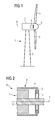
- the stator assembly 7 further comprises a frictional member, in the present embodiment a brake calliper system 13.
- the brake calliper system 13 is operatively configured for frictionally engaging at least a portion of the brake disc 12.
- the brake calliper system 13 extends radially outward from the stationary shaft 10 to the brake disc 12.
- the brake calliper system 13 comprises at least one brake calliper on each side of the brake disc 12 in order to enclose the brake disc 12.
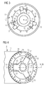
- FIG. 3 schematically shows a front view of a known brake system of the generator 6.
- the brake disc 12 comprises an inner surface 21.
- the inner surface 21 of the brake disc 12 comprises a number of recesses 15.
- the brake system further comprises a number of central mounted consoles or flanges 14, in the present embodiment three central mounted consoles or flanges 14.
- the consoles or flanges 14 are individually mounted to the stationary shaft 10.
- the consoles or flanges 14 are staggered about an angle of 120° regarding the circumference of the stationary shaft 10. Alternatively any other number of the consoles or flanges 14 is possible.
- the consoles or flanges 14 are arranged around the circumference of the stationary shaft 10 such that adjacent flanges have an equal distance to each other.
- the brake system comprises at least one rotor lock system 17.
- the rotor lock system 17 comprises at least one piston 16.
- the piston is located inside the console or flange 14 or is located inside of a lock casing.
- the lock casing can be connected to the console or flange 14.
- the brake system can comprise separate consoles or flanges for housing the pistons or for being connected with at least one lock casing of the rotor lock system 17 and separate consoles or flanges 14 being connected with the brake system, especially the brake calliper system 13.
- the pistons 16 are located such that they are prepared to engage with the recesses 15 in the inner surface 21 of the brake disc 12.
- FIG 4 schematically shows a perspective view of an inventive brake system.
- the brake system comprises an inventive component 20, which has the shape of a ring.
- the component 20 comprises means, for example a plurality of holes 23, for connecting it to a flange of the stator assembly 7, for example by means of bolts, pins or shims.
- the component can for instance be connected to a flange of the stationary shaft 10.
- the component 20 further comprises a central axis 26 and at least three radially outwardly protruding portions (wings) 22.
- the component 20 and the radially outwardly protruding portions 22 are made in one piece.
- the radially outwardly protruding portions 22 may comprise means (not shown in figure 4 ), for example a plurality of holes, for connecting the radially outwardly protruding portions 22 to frictional members 13 operatively configured for frictionally engaging at least a portion of the brake disc 12 and/or for connecting the radially outwardly protruding portions to a rotor lock system 17.
- the protruding portions (wings) 22 are staggered about an angle of 120° regarding the circumference of the component 20. Alternatively any other number or angle of the protruding portions 22 is possible. Preferably the protruding portions 22 are arranged around the circumference of the component 20 such that adjacent protruding portions 22 have an equal distance to each other.
- the inventive brake system further comprises a brake disc 12.
- the brake disc 12 may have the shape of a ring.
- the brake disc 12 comprises a plurality of holes 19 for connecting it to the rotor assembly 8 by means of a flange or threaded holes.
- the brake disc 12 may further comprise a number of holes 18 or other means for rotorlock pins configured for engaging into the holes.
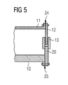
- Figure 5 schematically shows a sectional view of part of an inventive generator 6.
- the brake disc 12 is connected to the outer portion 11 of the rotor assembly 8 by means of a flange 24.
- the stator assembly 7, for example the central shaft 10, comprises a flange 25.
- the component 20 is connected to the stator assembly 7 by means of the flange 25.
- the component 20 is connected to the stator assembly 7, preferably to the stationary shaft 10 by means of the flange 25.
- the inventive method is applicable for manufacturing a generator or repairing or rebuilding or converting an existing generator.
- the component 20 After connecting the component 20 to the stator assembly 7, the component 20 can be aligned with a brake disc 12.
- the brake disc 12 may be connected to the rotor assembly 8 by means of the flange 24 or by means of threaded holes/pins in the rotor assembly.
- the outer portion 11 of the rotor assembly 8 may comprise the brake disc 12.
- the method may further comprise the step of placing pins in an interface between a fixed shaft flange 25 as well as for the rotor assembly 11 and the component 20 (not shown in figure 5 ). This may insure placement accuracy and additional strength in the assembly.
- the component 20 and/or a brake disc 12 can be prefabricated away from the generator production line and applicable for different generator types. Then a crane can take the component or the complete brake system and it can be mounted onto the generator line only adding bolts and/or pins and/or shims to align stator with rotor in the braking system.
Priority Applications (4)
| Application Number | Priority Date | Filing Date | Title |
|---|---|---|---|
| EP14151794.6A EP2896824B1 (de) | 2014-01-20 | 2014-01-20 | Bremssystem für einen Windturbinengenerator |
| DK14151794.6T DK2896824T3 (en) | 2014-01-20 | 2014-01-20 | Brake system for a wind turbine generator |
| US14/591,994 US20150204308A1 (en) | 2014-01-20 | 2015-01-08 | Brake system for a wind turbine generator |
| CN201510027197.2A CN104791191B (zh) | 2014-01-20 | 2015-01-20 | 风力涡轮机发电机的制动系统 |
Applications Claiming Priority (1)
| Application Number | Priority Date | Filing Date | Title |
|---|---|---|---|
| EP14151794.6A EP2896824B1 (de) | 2014-01-20 | 2014-01-20 | Bremssystem für einen Windturbinengenerator |
Publications (2)
| Publication Number | Publication Date |
|---|---|
| EP2896824A1 true EP2896824A1 (de) | 2015-07-22 |
| EP2896824B1 EP2896824B1 (de) | 2016-06-01 |
Family
ID=49955239
Family Applications (1)
| Application Number | Title | Priority Date | Filing Date |
|---|---|---|---|
| EP14151794.6A Active EP2896824B1 (de) | 2014-01-20 | 2014-01-20 | Bremssystem für einen Windturbinengenerator |
Country Status (3)
| Country | Link |
|---|---|
| US (1) | US20150204308A1 (de) |
| EP (1) | EP2896824B1 (de) |
| DK (1) | DK2896824T3 (de) |
Cited By (1)
| Publication number | Priority date | Publication date | Assignee | Title |
|---|---|---|---|---|
| WO2019141650A1 (de) * | 2018-01-17 | 2019-07-25 | Wobben Properties Gmbh | Arretier- und bremsmodul für eine windenergieanlage sowie generator und windenergieanlage mit selbigem |
Families Citing this family (2)
| Publication number | Priority date | Publication date | Assignee | Title |
|---|---|---|---|---|
| DE102016124379A1 (de) * | 2016-12-14 | 2018-06-14 | Wobben Properties Gmbh | Rotorarretiervorrichtung für eine Windenergieanlage und Verfahren |
| US20180320661A1 (en) * | 2017-05-03 | 2018-11-08 | General Electric Company | Compact Multi-Disk Rotor Brake System for a Wind Turbine |
Citations (6)
| Publication number | Priority date | Publication date | Assignee | Title |
|---|---|---|---|---|
| US20100079019A1 (en) * | 2008-09-30 | 2010-04-01 | General Electric Company | Wind turbine generator brake and grounding brush arrangement |
| US20100329867A1 (en) * | 2009-06-30 | 2010-12-30 | Patel Priyangu C | Drivetrain system for a wind turbine generator and method of assembling the same |
| DE102009048735A1 (de) * | 2009-10-08 | 2011-04-14 | Robert Bosch Gmbh | Antriebsstrang und Windkraftanlage |
| US20110121579A1 (en) * | 2009-11-26 | 2011-05-26 | Uffe Eriksen | Brake system, generator and wind turbine |
| EP2333326A1 (de) | 2009-11-26 | 2011-06-15 | Siemens Aktiengesellschaft | Bremssystem mit integrierter Rotorsperre für eine Windturbine, Generator und Windturbine |
| EP2590301A1 (de) * | 2011-11-04 | 2013-05-08 | Siemens Aktiengesellschaft | Generatoranordnung |
Family Cites Families (7)
| Publication number | Priority date | Publication date | Assignee | Title |
|---|---|---|---|---|
| DE102004013624A1 (de) * | 2004-03-19 | 2005-10-06 | Sb Contractor A/S | Verfahren zum Betreiben einer Windenergieanlage und Windenergieanlage |
| US7467530B2 (en) * | 2005-07-29 | 2008-12-23 | New Hampton Technologies Llc | Vehicle lock |
| US7360310B2 (en) * | 2005-10-05 | 2008-04-22 | General Electric Company | Method for changing removable bearing for a wind turbine generator |
| DE102007058746A1 (de) * | 2007-06-18 | 2008-12-24 | Hanning & Kahl Gmbh & Co. Kg | Arretierungsvorrichtung für eine Windturbine |
| DE102009017531A1 (de) * | 2009-04-17 | 2010-10-21 | Avantis Ltd. | Bremssystem eines Generators einer Windenergieanlage |
| JP4969712B1 (ja) * | 2011-09-22 | 2012-07-04 | 三菱重工業株式会社 | 再生エネルギー型発電装置及びその回転翼着脱方法 |
| EP2690284B1 (de) * | 2012-07-23 | 2015-08-26 | Siemens Aktiengesellschaft | Windturbinengenerator und Instandhaltung seines Hauptlagers |
-
2014
- 2014-01-20 DK DK14151794.6T patent/DK2896824T3/en active
- 2014-01-20 EP EP14151794.6A patent/EP2896824B1/de active Active
-
2015
- 2015-01-08 US US14/591,994 patent/US20150204308A1/en not_active Abandoned
Patent Citations (6)
| Publication number | Priority date | Publication date | Assignee | Title |
|---|---|---|---|---|
| US20100079019A1 (en) * | 2008-09-30 | 2010-04-01 | General Electric Company | Wind turbine generator brake and grounding brush arrangement |
| US20100329867A1 (en) * | 2009-06-30 | 2010-12-30 | Patel Priyangu C | Drivetrain system for a wind turbine generator and method of assembling the same |
| DE102009048735A1 (de) * | 2009-10-08 | 2011-04-14 | Robert Bosch Gmbh | Antriebsstrang und Windkraftanlage |
| US20110121579A1 (en) * | 2009-11-26 | 2011-05-26 | Uffe Eriksen | Brake system, generator and wind turbine |
| EP2333326A1 (de) | 2009-11-26 | 2011-06-15 | Siemens Aktiengesellschaft | Bremssystem mit integrierter Rotorsperre für eine Windturbine, Generator und Windturbine |
| EP2590301A1 (de) * | 2011-11-04 | 2013-05-08 | Siemens Aktiengesellschaft | Generatoranordnung |
Cited By (1)
| Publication number | Priority date | Publication date | Assignee | Title |
|---|---|---|---|---|
| WO2019141650A1 (de) * | 2018-01-17 | 2019-07-25 | Wobben Properties Gmbh | Arretier- und bremsmodul für eine windenergieanlage sowie generator und windenergieanlage mit selbigem |
Also Published As
| Publication number | Publication date |
|---|---|
| US20150204308A1 (en) | 2015-07-23 |
| EP2896824B1 (de) | 2016-06-01 |
| DK2896824T3 (en) | 2016-08-29 |
| CN104791191A (zh) | 2015-07-22 |
Similar Documents
| Publication | Publication Date | Title |
|---|---|---|
| JP5773621B2 (ja) | 一体化されたロータロックを備えた風車のためのブレーキシステム、発電機、及び風車 | |
| JP5717413B2 (ja) | ブレーキシステム、発電機、及び風車 | |
| US9581137B2 (en) | Yaw brakes for wind turbines | |
| US8975770B2 (en) | Wind power turbine electric generator and wind power turbine equipped with an electric generator | |
| EP3309387A1 (de) | Lagerstützvorrichtung für eine windkraftgeneratoranordnung und installationsverfahren dafür und windenergiegeneratoranordnung | |
| CN107294273B (zh) | 借助于转动装置的发电机的旋转运动控制 | |
| EP2192299A2 (de) | Anordnung zur Wellenverbindung in einer Windkraftanlage | |
| EP2896824B1 (de) | Bremssystem für einen Windturbinengenerator | |
| CN104234928A (zh) | 用于使风力涡轮机的转子转动的装置和方法 | |
| CN105386941B (zh) | 风力涡轮机转子锁定系统 | |
| RU2722121C1 (ru) | Арретирующее устройство для ротора ветроэнергетической установки и способ | |
| EP2783104B1 (de) | Windturbine mit einem Blattverstellsystem | |
| US20120080969A1 (en) | Rotor, generator and wind turbine | |
| EP3464886B1 (de) | Windturbine mit einem rotorverriegelungssystem und verfahren dafür | |
| US11560877B2 (en) | Shaft-to-shaft connector for a wind turbine | |
| DK178005B1 (en) | Wind Rotor Brake System | |
| US20190195197A1 (en) | Rotor arresting device for a wind turbine and method | |
| CN104791191B (zh) | 风力涡轮机发电机的制动系统 |
Legal Events
| Date | Code | Title | Description |
|---|---|---|---|
| PUAI | Public reference made under article 153(3) epc to a published international application that has entered the european phase |
Free format text: ORIGINAL CODE: 0009012 |
|
| 17P | Request for examination filed |
Effective date: 20140120 |
|
| AK | Designated contracting states |
Kind code of ref document: A1 Designated state(s): AL AT BE BG CH CY CZ DE DK EE ES FI FR GB GR HR HU IE IS IT LI LT LU LV MC MK MT NL NO PL PT RO RS SE SI SK SM TR |
|
| AX | Request for extension of the european patent |
Extension state: BA ME |
|
| 17P | Request for examination filed |
Effective date: 20150805 |
|
| RBV | Designated contracting states (corrected) |
Designated state(s): AL AT BE BG CH CY CZ DE DK EE ES FI FR GB GR HR HU IE IS IT LI LT LU LV MC MK MT NL NO PL PT RO RS SE SI SK SM TR |
|
| GRAP | Despatch of communication of intention to grant a patent |
Free format text: ORIGINAL CODE: EPIDOSNIGR1 |
|
| INTG | Intention to grant announced |
Effective date: 20151222 |
|
| GRAS | Grant fee paid |
Free format text: ORIGINAL CODE: EPIDOSNIGR3 |
|
| GRAA | (expected) grant |
Free format text: ORIGINAL CODE: 0009210 |
|
| AK | Designated contracting states |
Kind code of ref document: B1 Designated state(s): AL AT BE BG CH CY CZ DE DK EE ES FI FR GB GR HR HU IE IS IT LI LT LU LV MC MK MT NL NO PL PT RO RS SE SI SK SM TR |
|
| REG | Reference to a national code |
Ref country code: GB Ref legal event code: FG4D |
|
| REG | Reference to a national code |
Ref country code: CH Ref legal event code: EP Ref country code: AT Ref legal event code: REF Ref document number: 804040 Country of ref document: AT Kind code of ref document: T Effective date: 20160615 |
|
| REG | Reference to a national code |
Ref country code: IE Ref legal event code: FG4D |
|
| REG | Reference to a national code |
Ref country code: DE Ref legal event code: R096 Ref document number: 602014002150 Country of ref document: DE |
|
| REG | Reference to a national code |
Ref country code: DK Ref legal event code: T3 Effective date: 20160822 |
|
| REG | Reference to a national code |
Ref country code: LT Ref legal event code: MG4D |
|
| REG | Reference to a national code |
Ref country code: NL Ref legal event code: MP Effective date: 20160601 |
|
| PG25 | Lapsed in a contracting state [announced via postgrant information from national office to epo] |
Ref country code: FI Free format text: LAPSE BECAUSE OF FAILURE TO SUBMIT A TRANSLATION OF THE DESCRIPTION OR TO PAY THE FEE WITHIN THE PRESCRIBED TIME-LIMIT Effective date: 20160601 Ref country code: NO Free format text: LAPSE BECAUSE OF FAILURE TO SUBMIT A TRANSLATION OF THE DESCRIPTION OR TO PAY THE FEE WITHIN THE PRESCRIBED TIME-LIMIT Effective date: 20160901 Ref country code: LT Free format text: LAPSE BECAUSE OF FAILURE TO SUBMIT A TRANSLATION OF THE DESCRIPTION OR TO PAY THE FEE WITHIN THE PRESCRIBED TIME-LIMIT Effective date: 20160601 |
|
| REG | Reference to a national code |
Ref country code: AT Ref legal event code: MK05 Ref document number: 804040 Country of ref document: AT Kind code of ref document: T Effective date: 20160601 |
|
| PG25 | Lapsed in a contracting state [announced via postgrant information from national office to epo] |
Ref country code: LV Free format text: LAPSE BECAUSE OF FAILURE TO SUBMIT A TRANSLATION OF THE DESCRIPTION OR TO PAY THE FEE WITHIN THE PRESCRIBED TIME-LIMIT Effective date: 20160601 Ref country code: NL Free format text: LAPSE BECAUSE OF FAILURE TO SUBMIT A TRANSLATION OF THE DESCRIPTION OR TO PAY THE FEE WITHIN THE PRESCRIBED TIME-LIMIT Effective date: 20160601 Ref country code: RS Free format text: LAPSE BECAUSE OF FAILURE TO SUBMIT A TRANSLATION OF THE DESCRIPTION OR TO PAY THE FEE WITHIN THE PRESCRIBED TIME-LIMIT Effective date: 20160601 Ref country code: GR Free format text: LAPSE BECAUSE OF FAILURE TO SUBMIT A TRANSLATION OF THE DESCRIPTION OR TO PAY THE FEE WITHIN THE PRESCRIBED TIME-LIMIT Effective date: 20160902 Ref country code: ES Free format text: LAPSE BECAUSE OF FAILURE TO SUBMIT A TRANSLATION OF THE DESCRIPTION OR TO PAY THE FEE WITHIN THE PRESCRIBED TIME-LIMIT Effective date: 20160601 Ref country code: SE Free format text: LAPSE BECAUSE OF FAILURE TO SUBMIT A TRANSLATION OF THE DESCRIPTION OR TO PAY THE FEE WITHIN THE PRESCRIBED TIME-LIMIT Effective date: 20160601 Ref country code: HR Free format text: LAPSE BECAUSE OF FAILURE TO SUBMIT A TRANSLATION OF THE DESCRIPTION OR TO PAY THE FEE WITHIN THE PRESCRIBED TIME-LIMIT Effective date: 20160601 |
|
| PG25 | Lapsed in a contracting state [announced via postgrant information from national office to epo] |
Ref country code: SK Free format text: LAPSE BECAUSE OF FAILURE TO SUBMIT A TRANSLATION OF THE DESCRIPTION OR TO PAY THE FEE WITHIN THE PRESCRIBED TIME-LIMIT Effective date: 20160601 Ref country code: IT Free format text: LAPSE BECAUSE OF FAILURE TO SUBMIT A TRANSLATION OF THE DESCRIPTION OR TO PAY THE FEE WITHIN THE PRESCRIBED TIME-LIMIT Effective date: 20160601 Ref country code: RO Free format text: LAPSE BECAUSE OF FAILURE TO SUBMIT A TRANSLATION OF THE DESCRIPTION OR TO PAY THE FEE WITHIN THE PRESCRIBED TIME-LIMIT Effective date: 20160601 Ref country code: EE Free format text: LAPSE BECAUSE OF FAILURE TO SUBMIT A TRANSLATION OF THE DESCRIPTION OR TO PAY THE FEE WITHIN THE PRESCRIBED TIME-LIMIT Effective date: 20160601 Ref country code: IS Free format text: LAPSE BECAUSE OF FAILURE TO SUBMIT A TRANSLATION OF THE DESCRIPTION OR TO PAY THE FEE WITHIN THE PRESCRIBED TIME-LIMIT Effective date: 20161001 Ref country code: CZ Free format text: LAPSE BECAUSE OF FAILURE TO SUBMIT A TRANSLATION OF THE DESCRIPTION OR TO PAY THE FEE WITHIN THE PRESCRIBED TIME-LIMIT Effective date: 20160601 |
|
| PG25 | Lapsed in a contracting state [announced via postgrant information from national office to epo] |
Ref country code: PL Free format text: LAPSE BECAUSE OF FAILURE TO SUBMIT A TRANSLATION OF THE DESCRIPTION OR TO PAY THE FEE WITHIN THE PRESCRIBED TIME-LIMIT Effective date: 20160601 Ref country code: BE Free format text: LAPSE BECAUSE OF FAILURE TO SUBMIT A TRANSLATION OF THE DESCRIPTION OR TO PAY THE FEE WITHIN THE PRESCRIBED TIME-LIMIT Effective date: 20160601 Ref country code: PT Free format text: LAPSE BECAUSE OF FAILURE TO SUBMIT A TRANSLATION OF THE DESCRIPTION OR TO PAY THE FEE WITHIN THE PRESCRIBED TIME-LIMIT Effective date: 20161003 Ref country code: AT Free format text: LAPSE BECAUSE OF FAILURE TO SUBMIT A TRANSLATION OF THE DESCRIPTION OR TO PAY THE FEE WITHIN THE PRESCRIBED TIME-LIMIT Effective date: 20160601 Ref country code: SM Free format text: LAPSE BECAUSE OF FAILURE TO SUBMIT A TRANSLATION OF THE DESCRIPTION OR TO PAY THE FEE WITHIN THE PRESCRIBED TIME-LIMIT Effective date: 20160601 |
|
| REG | Reference to a national code |
Ref country code: DE Ref legal event code: R097 Ref document number: 602014002150 Country of ref document: DE |
|
| PLBE | No opposition filed within time limit |
Free format text: ORIGINAL CODE: 0009261 |
|
| STAA | Information on the status of an ep patent application or granted ep patent |
Free format text: STATUS: NO OPPOSITION FILED WITHIN TIME LIMIT |
|
| 26N | No opposition filed |
Effective date: 20170302 |
|
| PG25 | Lapsed in a contracting state [announced via postgrant information from national office to epo] |
Ref country code: SI Free format text: LAPSE BECAUSE OF FAILURE TO SUBMIT A TRANSLATION OF THE DESCRIPTION OR TO PAY THE FEE WITHIN THE PRESCRIBED TIME-LIMIT Effective date: 20160601 |
|
| REG | Reference to a national code |
Ref country code: CH Ref legal event code: PL |
|
| PG25 | Lapsed in a contracting state [announced via postgrant information from national office to epo] |
Ref country code: MC Free format text: LAPSE BECAUSE OF FAILURE TO SUBMIT A TRANSLATION OF THE DESCRIPTION OR TO PAY THE FEE WITHIN THE PRESCRIBED TIME-LIMIT Effective date: 20160601 |
|
| REG | Reference to a national code |
Ref country code: FR Ref legal event code: ST Effective date: 20170929 |
|
| PG25 | Lapsed in a contracting state [announced via postgrant information from national office to epo] |
Ref country code: FR Free format text: LAPSE BECAUSE OF NON-PAYMENT OF DUE FEES Effective date: 20170131 Ref country code: LI Free format text: LAPSE BECAUSE OF NON-PAYMENT OF DUE FEES Effective date: 20170131 Ref country code: CH Free format text: LAPSE BECAUSE OF NON-PAYMENT OF DUE FEES Effective date: 20170131 |
|
| REG | Reference to a national code |
Ref country code: IE Ref legal event code: MM4A |
|
| PG25 | Lapsed in a contracting state [announced via postgrant information from national office to epo] |
Ref country code: LU Free format text: LAPSE BECAUSE OF NON-PAYMENT OF DUE FEES Effective date: 20170120 |
|
| PG25 | Lapsed in a contracting state [announced via postgrant information from national office to epo] |
Ref country code: IE Free format text: LAPSE BECAUSE OF NON-PAYMENT OF DUE FEES Effective date: 20170120 |
|
| PG25 | Lapsed in a contracting state [announced via postgrant information from national office to epo] |
Ref country code: MT Free format text: LAPSE BECAUSE OF NON-PAYMENT OF DUE FEES Effective date: 20170120 |
|
| PG25 | Lapsed in a contracting state [announced via postgrant information from national office to epo] |
Ref country code: AL Free format text: LAPSE BECAUSE OF FAILURE TO SUBMIT A TRANSLATION OF THE DESCRIPTION OR TO PAY THE FEE WITHIN THE PRESCRIBED TIME-LIMIT Effective date: 20160601 |
|
| PG25 | Lapsed in a contracting state [announced via postgrant information from national office to epo] |
Ref country code: HU Free format text: LAPSE BECAUSE OF FAILURE TO SUBMIT A TRANSLATION OF THE DESCRIPTION OR TO PAY THE FEE WITHIN THE PRESCRIBED TIME-LIMIT; INVALID AB INITIO Effective date: 20140120 |
|
| REG | Reference to a national code |
Ref country code: DE Ref legal event code: R081 Ref document number: 602014002150 Country of ref document: DE Owner name: SIEMENS GAMESA RENEWABLE ENERGY A/S, DK Free format text: FORMER OWNER: SIEMENS AKTIENGESELLSCHAFT, 80333 MUENCHEN, DE |
|
| PG25 | Lapsed in a contracting state [announced via postgrant information from national office to epo] |
Ref country code: BG Free format text: LAPSE BECAUSE OF FAILURE TO SUBMIT A TRANSLATION OF THE DESCRIPTION OR TO PAY THE FEE WITHIN THE PRESCRIBED TIME-LIMIT Effective date: 20160601 |
|
| PG25 | Lapsed in a contracting state [announced via postgrant information from national office to epo] |
Ref country code: CY Free format text: LAPSE BECAUSE OF FAILURE TO SUBMIT A TRANSLATION OF THE DESCRIPTION OR TO PAY THE FEE WITHIN THE PRESCRIBED TIME-LIMIT Effective date: 20160601 |
|
| PG25 | Lapsed in a contracting state [announced via postgrant information from national office to epo] |
Ref country code: MK Free format text: LAPSE BECAUSE OF FAILURE TO SUBMIT A TRANSLATION OF THE DESCRIPTION OR TO PAY THE FEE WITHIN THE PRESCRIBED TIME-LIMIT Effective date: 20160601 |
|
| REG | Reference to a national code |
Ref country code: GB Ref legal event code: 732E Free format text: REGISTERED BETWEEN 20191128 AND 20191204 |
|
| PG25 | Lapsed in a contracting state [announced via postgrant information from national office to epo] |
Ref country code: TR Free format text: LAPSE BECAUSE OF FAILURE TO SUBMIT A TRANSLATION OF THE DESCRIPTION OR TO PAY THE FEE WITHIN THE PRESCRIBED TIME-LIMIT Effective date: 20160601 |
|
| PGFP | Annual fee paid to national office [announced via postgrant information from national office to epo] |
Ref country code: DK Payment date: 20230123 Year of fee payment: 10 |
|
| PGFP | Annual fee paid to national office [announced via postgrant information from national office to epo] |
Ref country code: GB Payment date: 20230124 Year of fee payment: 10 Ref country code: DE Payment date: 20230119 Year of fee payment: 10 |