EP2896218B1 - Coaxial loudspeaker arrangement - Google Patents
Coaxial loudspeaker arrangement Download PDFInfo
- Publication number
- EP2896218B1 EP2896218B1 EP13774496.7A EP13774496A EP2896218B1 EP 2896218 B1 EP2896218 B1 EP 2896218B1 EP 13774496 A EP13774496 A EP 13774496A EP 2896218 B1 EP2896218 B1 EP 2896218B1
- Authority
- EP
- European Patent Office
- Prior art keywords
- ferrite core
- magnet
- loudspeaker arrangement
- plane surface
- diaphragm
- Prior art date
- Legal status (The legal status is an assumption and is not a legal conclusion. Google has not performed a legal analysis and makes no representation as to the accuracy of the status listed.)
- Active
Links
- 229910000859 α-Fe Inorganic materials 0.000 claims description 109
- 238000004804 winding Methods 0.000 claims description 9
- 229910052779 Neodymium Inorganic materials 0.000 claims description 6
- QEFYFXOXNSNQGX-UHFFFAOYSA-N neodymium atom Chemical compound [Nd] QEFYFXOXNSNQGX-UHFFFAOYSA-N 0.000 claims description 6
- 239000000463 material Substances 0.000 claims description 5
- 239000000725 suspension Substances 0.000 description 5
- 241000239290 Araneae Species 0.000 description 3
- 238000010586 diagram Methods 0.000 description 3
- 239000004411 aluminium Substances 0.000 description 2
- 229910052782 aluminium Inorganic materials 0.000 description 2
- XAGFODPZIPBFFR-UHFFFAOYSA-N aluminium Chemical compound [Al] XAGFODPZIPBFFR-UHFFFAOYSA-N 0.000 description 2
- 230000007423 decrease Effects 0.000 description 2
- 230000001419 dependent effect Effects 0.000 description 2
- 239000000428 dust Substances 0.000 description 2
- 229910052751 metal Inorganic materials 0.000 description 2
- 239000002184 metal Substances 0.000 description 2
- 230000035945 sensitivity Effects 0.000 description 2
- 229910000838 Al alloy Inorganic materials 0.000 description 1
- 229910000583 Nd alloy Inorganic materials 0.000 description 1
- 239000000853 adhesive Substances 0.000 description 1
- 230000001070 adhesive effect Effects 0.000 description 1
- 238000010276 construction Methods 0.000 description 1
- 230000003247 decreasing effect Effects 0.000 description 1
- 230000000694 effects Effects 0.000 description 1
- 230000004907 flux Effects 0.000 description 1
- 238000004519 manufacturing process Methods 0.000 description 1
- 238000005259 measurement Methods 0.000 description 1
- 238000012986 modification Methods 0.000 description 1
- 230000004048 modification Effects 0.000 description 1
Images

Classifications
-
- H—ELECTRICITY
- H04—ELECTRIC COMMUNICATION TECHNIQUE
- H04R—LOUDSPEAKERS, MICROPHONES, GRAMOPHONE PICK-UPS OR LIKE ACOUSTIC ELECTROMECHANICAL TRANSDUCERS; DEAF-AID SETS; PUBLIC ADDRESS SYSTEMS
- H04R7/00—Diaphragms for electromechanical transducers; Cones
- H04R7/16—Mounting or tensioning of diaphragms or cones
-
- H—ELECTRICITY
- H04—ELECTRIC COMMUNICATION TECHNIQUE
- H04R—LOUDSPEAKERS, MICROPHONES, GRAMOPHONE PICK-UPS OR LIKE ACOUSTIC ELECTROMECHANICAL TRANSDUCERS; DEAF-AID SETS; PUBLIC ADDRESS SYSTEMS
- H04R1/00—Details of transducers, loudspeakers or microphones
- H04R1/20—Arrangements for obtaining desired frequency or directional characteristics
- H04R1/22—Arrangements for obtaining desired frequency or directional characteristics for obtaining desired frequency characteristic only
- H04R1/24—Structural combinations of separate transducers or of two parts of the same transducer and responsive respectively to two or more frequency ranges
-
- H—ELECTRICITY
- H04—ELECTRIC COMMUNICATION TECHNIQUE
- H04R—LOUDSPEAKERS, MICROPHONES, GRAMOPHONE PICK-UPS OR LIKE ACOUSTIC ELECTROMECHANICAL TRANSDUCERS; DEAF-AID SETS; PUBLIC ADDRESS SYSTEMS
- H04R7/00—Diaphragms for electromechanical transducers; Cones
- H04R7/02—Diaphragms for electromechanical transducers; Cones characterised by the construction
-
- H—ELECTRICITY
- H04—ELECTRIC COMMUNICATION TECHNIQUE
- H04R—LOUDSPEAKERS, MICROPHONES, GRAMOPHONE PICK-UPS OR LIKE ACOUSTIC ELECTROMECHANICAL TRANSDUCERS; DEAF-AID SETS; PUBLIC ADDRESS SYSTEMS
- H04R9/00—Transducers of moving-coil, moving-strip, or moving-wire type
- H04R9/02—Details
- H04R9/025—Magnetic circuit
-
- H—ELECTRICITY
- H04—ELECTRIC COMMUNICATION TECHNIQUE
- H04R—LOUDSPEAKERS, MICROPHONES, GRAMOPHONE PICK-UPS OR LIKE ACOUSTIC ELECTROMECHANICAL TRANSDUCERS; DEAF-AID SETS; PUBLIC ADDRESS SYSTEMS
- H04R9/00—Transducers of moving-coil, moving-strip, or moving-wire type
- H04R9/02—Details
- H04R9/04—Construction, mounting, or centering of coil
-
- H—ELECTRICITY
- H04—ELECTRIC COMMUNICATION TECHNIQUE
- H04R—LOUDSPEAKERS, MICROPHONES, GRAMOPHONE PICK-UPS OR LIKE ACOUSTIC ELECTROMECHANICAL TRANSDUCERS; DEAF-AID SETS; PUBLIC ADDRESS SYSTEMS
- H04R1/00—Details of transducers, loudspeakers or microphones
- H04R1/20—Arrangements for obtaining desired frequency or directional characteristics
- H04R1/32—Arrangements for obtaining desired frequency or directional characteristics for obtaining desired directional characteristic only
- H04R1/40—Arrangements for obtaining desired frequency or directional characteristics for obtaining desired directional characteristic only by combining a number of identical transducers
- H04R1/403—Arrangements for obtaining desired frequency or directional characteristics for obtaining desired directional characteristic only by combining a number of identical transducers loud-speakers
-
- H—ELECTRICITY
- H04—ELECTRIC COMMUNICATION TECHNIQUE
- H04R—LOUDSPEAKERS, MICROPHONES, GRAMOPHONE PICK-UPS OR LIKE ACOUSTIC ELECTROMECHANICAL TRANSDUCERS; DEAF-AID SETS; PUBLIC ADDRESS SYSTEMS
- H04R9/00—Transducers of moving-coil, moving-strip, or moving-wire type
- H04R9/02—Details
- H04R9/04—Construction, mounting, or centering of coil
- H04R9/046—Construction
Definitions
- the present invention relates to a coaxial loudspeaker arrangement with an outer diaphragm for operating in a lower frequency range, an inner diaphragm for operating in a higher frequency range, both located in a common loudspeaker frame, with an outer voice coil connected to the outer diaphragm, an inner voice coil connected to the inner diaphragm, two coaxially arranged magnets, and ferrite cores in association with the magnets, wherein the voice coils extend into air gaps between the ferrite cores, and the diaphragms are connected to the loudspeaker frame through flexible suspending elements.
- Loudspeakers as electro-acoustic converters are in known in a great variety (as for power and frequency range).
- a speaker with only one diaphragm is not suitable for providing full performance over the whole audible frequency range, in order to provide better acoustic performance, more, preferably two (high- and low-range) or three (high- middle and low-range) speakers are combined in a speaker system, which can be connected to an output of an acoustic power amplifier via a two- or three-way crossover.
- speaker systems with multiple speakers of that kind can only be mounted into relatively large speaker boxes.
- a solution is provided by a coaxial arrangement of the different speakers in a common frame.
- Current loudspeakers of car radios and of car amplifiers have generally coaxial arrangement, providing a relatively wide audio frequency range with little space requirement. Due to the smaller size, the loudspeakers with coaxial configuration have less power output, e.g. the current load capacity is more limited when compared to multi-speaker systems of larger size. Higher voltage- or current load in such conventional multi-speaker systems will lead to higher distortion and shorter life time.
- Patent document DE19913558 discloses a coaxial loudspeaker, in which between the voice coil of the outer subwoofer diaphragm and the voice coil of the inner tweeter diaphragm, there is only a single common magnetic circuit between ferrite cores.
- the loudspeaker is small in size and weight, but it is not suitable to provide higher power audio output.
- a further problem arises from the fact that both of the diaphragm voice coils move in a magnetic field of substantially the same strength, which, without appropriate frequency dependent compensation, would cause distortion.
- the present invention relates to a coaxial loudspeaker arrangement with an outer diaphragm for operating in a lower frequency range, an inner diaphragm for operating in a higher frequency range, both located in a common loudspeaker frame, with an outer voice coil connected to the outer diaphragm, an inner voice coil connected to the inner diaphragm, two coaxially arranged magnets, and ferrite cores in association with the magnets, wherein the voice coils extend into air gaps between the ferrite cores and the diaphragms are connected to the loudspeaker frame through flexible suspending elements.
- the coaxial loudspeaker arrangement comprises an inner core and an outer core separated from each other by an inner air gap, between an outer magnet and an inner magnet, one ferrite core of the outer magnet is separated by an outer air gap from the outer core located between the two magnets, wherein the voice coil of the outer diaphragm extends into the outer air gap and the voice coil of the inner diaphragm extends into the inner air gap.
- the outer magnet is oriented axially with its magnetic poles
- the inner magnet is oriented radially with its magnetic poles
- an intermediate ferrite core is arranged, which is separated from the inner ferrite core of the inner magnet by the inner air gap and from the upper ferrite core of the outer magnet by the outer air gap.
- Such a design ensures that the two voice coils will operate in magnetic fields of different strength, and the two magnets provide for both voice coils a magnetic field of sufficiently high strength. With increasing magnetic field, the sensitivity of the loudspeaker and the power output will be higher. The voice coils operating in magnetic fields of different strength will decrease the distortion of the loudspeaker even at a higher power output.
- At least a part of the inner magnet and at least a part of the outer magnet is located in the same plane.
- This configuration enables the reduction of the size of the loudspeaker.
- the upper plane surface of the inner magnet is located preferably in proximity of the upper plane surface of the outer magnet, above the upper plane surface of the outer magnet, and the lower plane surface of the inner magnet is located between the upper plane surface and the lower plane surface of the outer magnet.
- the outer magnet is located between a lower and an upper core (pole core), wherein the outer diameter of the two ferrite cores is substantially equal to the outer dimension of the outer magnet, and air gap between the inner diameter of the upper ferrite core and the outer diameter of the outer ferrite core is selected in accordance with the dimension of the outer voice coil.
- the upper plain surface of the outer magnet is located substantially in the same plane as the upper plane surface of the upper ferrite core, and the upper plane surface of the inner ferrite core is located in proximity of the upper plane surface of the intermediate ferrite core, below the upper plane surface of the intermediate ferrite core.
- the outer ferrite core comprises a head portion adjacent to the inner voice coil, and a foot portion fitting to the inner ferrite core, wherein the air gap between the inner diameter of the head portion of the intermediate ferrite core and the outer diameter of the inner ferrite core is selected in accordance with the dimension of the inner voice coil.
- a hollow middle portion is formed between the head portion and the foot portion of the intermediate ferrite core, and the head portion comprises a conical surface extending from a higher outer wall to a lower inner wall.
- the inner ferrite core has a substantially cylindrical shape with a recess in the upper part for accommodating the inner magnet. This recess can be used for positioning the inner magnet, e.g. for locating the inner magnet coaxially with the loudspeaker axis.
- the upper plane surface of the inner ferrite core is located preferably higher than the upper plane surface of the inner magnet, thus the inner magnet inserted into the inner ferrite core can be covered with a ferrite core having the shape of a circular disc and fitting within the recess of the inner ferrite core.
- a circumferential recess is formed for fitting with the inner edge of the lower ferrite core.
- This recess can be used for positioning the inner ferrite core, e.g. for locating the inner ferrite core coaxially with the loudspeaker axis.
- the north pole and the south pole of the outer magnet are directed preferably towards the upper and lower ferrite core.
- the north pole and the south pole of the inner magnet are directed inwardly and outwardly, and the outwardly directed pole of the inner magnet is identical with the pole of the outer magnet which is directed to the upper ferrite core.
- At least one of the voice coils has multiple layers, wherein the number of layers above each other is variable along the coil.
- the voice coil has a conical shape in cross section, with more windings above each other on the diaphragm side, and less windings on the other side opposite the diaphragm. Such a configuration may contribute to a substantial reduction of the unpleasant audio effect, generally known from conventional loudspeakers, which is produced when a driving power amplifier is connected or the level of the audio frequency signal changes to a great extent.
- the magnets used for the loudspeaker arrangement according to the present invention are permanent magnets with a material of neodymium or comprising neodymium.
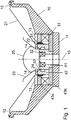
- a coaxial loudspeaker arrangement according to the present invention is shown in a lateral cross-sectional view.
- the coaxial loudspeaker arrangement has a common loudspeaker frame 10 with a disc shaped base plate 11, with radially extending ribs which are connected and terminated by a circular rim.
- the loudspeaker frame is basically non magnetic, and thus can be prepared from a plastic material. In order to withstand higher strain and power, it may be preferably made of a non magnetic metal, advantageously of aluminium or an aluminium alloy.
- a loudspeaker frame of metal, such as aluminium is also suitable for heat transfer.
- An outer diaphragm 21 operating in a lower frequency band and provided with an outer voice coil 22 is secured to the circular upper rim and a circular lower rim through flexible suspension elements (spider) 12 and 13.
- An inner diaphragm 23 provided with an inner voice coil 24 and operating in a higher frequency band is arranged concentric to the outer diaphragm and is secured to the intermediate ferrite core 42 through flexible suspension elements (spider) 14.
- the loudspeaker arrangement has two coaxially arranged magnets 31 and 32 and ferrite cores 41, 42 and 43 are associated with the magnets.
- the voice coils 22 and 24 extend into the air gaps 51, 52 between the ferrite cores.
- the outer diaphragm 21 is connected to the loudspeaker frame 10 through flexible suspension elements 12 and 13.
- the inner diaphragm 14 is coupled to a ferrite core 42 through a flexible suspension element 14.
- the opening of the inner diaphragm 23 is covered by a dust cap 25.
- an inner core 41 and an intermediate core 42 located between the outer magnet 31 and the inner magnet 32 and separated from each other by an inner air gap 52.
- the upper ferrite core 43a above the outer magnet 31 is separated from the intermediate core 42 located between the two magnets by an outer air gap 51.
- the voice coil 22 of the outer diaphragm 21 extends into the outer air gap 51 and the voice coil 24 of the inner diaphragm 23 extends into the inner air gap 52.
- At least a part of the inner magnet 32 and at least a part of the outer magnet 31 is located in the same plane.
- the upper plane surface of the inner magnet 32 is located preferably in proximity of the upper plane surface of the outer magnet 31, above the upper plane surface of the outer magnet 31, and the lower plane surface of the inner magnet 32 is located between the upper plane surface and the lower plane surface of the outer magnet 31.
- the outer magnet 31 is located between a lower and an upper ferrite core 43a, 43b, wherein the outer diameter of the two ferrite cores 43a, 43b is essentially equal to the outer dimension of the outer magnet 31.
- the dimension of the air gap 51 between the inner diameter of the upper ferrite core 43a and the outer diameter of the intermediate ferrite core 42 is selected in accordance with the dimension of the outer voice coil 22.
- the dimension of the outer air gap 51 is between 2 and 4 mm, preferably 3 mm.
- the upper plain surface of the intermediate ferrite core 42 is located substantially in the same plane as the upper plane surface of the upper ferrite core 43a, and the upper plane surface of the inner ferrite core 41 is located in proximity of the upper plane surface of the intermediate ferrite core 42, below the upper plane surface of the intermediate ferrite core 42.
- the intermediate ferrite core 42 comprises a head portion adjacent to the inner voice coil 24, and a foot portion fitting to the inner ferrite core 41.
- the dimension of the air gap 52 between the inner diameter of the head portion of the outer ferrite core 42 and the outer diameter of the inner ferrite core 41 is selected in accordance with the dimension of the inner voice coil 24.
- the dimension of the inner air gap 52 is between 1 and 2 mm, preferably 1,5 mm.
- a hollow middle portion is formed between the head portion and the foot portion of the intermediate ferrite core 42, and the head portion comprises a conical surface extending from a higher outer wall to a lower inner wall.
- the inner ferrite core 41 has a substantially cylindrical shape with a recess in the upper part for receiving the inner magnet 32.
- the upper plane surface of the inner ferrite core 41 is located higher than the upper plane surface of the inner magnet 32, thus the inner magnet 32 inserted into the inner ferrite core 41 can be covered with a ferrite core 44 having the shape of a circular disc and fitting within the recess of the inner ferrite core 41.
- the ferrite core 44 is provided with a central opening with a dimension substantially equal to the dimension of the inner opening of the inner magnet 32.
- the opening of the ferrite core 44 has a conical wall with a smaller diameter being equal to the inner diameter of the inner magnet 32 and the diameter of the opening decreases upwardly.
- a circumferential recess is formed to mate with the inner edge of the lower ferrite core 43b.
- the north pole and the south pole of the outer magnet 31 are directed towards the upper and lower ferrite core 43a, 43b.
- the north pole and the south pole of the inner magnet 32 are directed inwardly and outwardly, respectively, and the outwardly directed pole of the inner magnet 32, in the drawing the North pole, is identical with the pole of the outer magnet 31 which is directed to the upper ferrite core 43a.
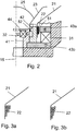
- the voice coils used has a multilayered coil, wherein the number of windings above each other is variable along the coil.
- the variable coil layer thickness is preferably achieved by applying less layers, e.g. one layer in the air gap region with higher magnetic field strength, and by applying more layers, e.g. two or three layers farther away.
- the voice coil has a substantially conical shape in cross section, with more windings above each other on the diaphragm side, and less windings on the other side opposite the diaphragm.
- the layer thickness changes in a stepwise manner, while according to Fig. 3b .
- the layer thickness changes more continuously, as the wire of the individual layers is located partially in the winding gaps.
- the material used for the permanent magnets is neodymium or it comprises neodymium, such as an alloy of neodymium, such as N52.
- neodymium such as an alloy of neodymium, such as N52.
- the use of such a magnet material or a similarly high strength magnet can increase the sensitivity and the output power of the loudspeaker assembly.
- the parts of the loudspeaker assembly are constructed in order to simplify the production and the assembling, and to ensure a correct locating and positioning of the individual parts.
- the lower ferrite core 43b which has a central opening for receiving and positioning the inner core 41 with a fitting recess.
- the ferrite core 43b carries the outer magnet 31 which is also enclosed by the cylindrical inner wall of the loudspeaker frame 10.
- An intermediate ferrite core 42 may be pulled over the inner ferrite core 41, wherein the intermediate core fits with its foot portion exactly to the outer diameter of the inner ferrite core 41.
- An upper ferrite core 43a may be arranged on the outer magnet 31, wherein the upper core fits with its outer diameter to the inner diameter of the receiving recess of the loudspeaker frame 10.
- An inner magnet 32 can be received in an inner recess of the inner ferrite core 41, wherein the upper plane surface of the inner magnet 32 is located below the upper plain surface of the inner ferrite core 41.
- the inner magnet 32 can be covered with a disc shaped ferrite core 44. All of the individual elements fitted to each other are located concentric relative to the axis of the loudspeaker 15.
- the magnets and the ferrite cores may be attached to the loudspeaker frame 10 and to each other e.g. by an adhesive.
- the outer diaphragm can be inserted which is followed by the inner diaphragm, wherein both of the diaphragms can be attached through flexible suspending elements.
- Fig. 4 shows the frequency response diagram of the coaxial loudspeaker arrangement according to the present invention.
- the horizontal axis shows the frequency in Hz, on a logarithmic scale, while the vertical axis shows the power output of the loudspeaker in dB.
- the nominal power of the loudspeaker was 150 W, and the average acoustic pressure 100 dB.
- the loudspeaker provided in the frequency range between 50 Hz and 10 kHz a minimum acoustic pressure of 100 dB.
- the diameter of the outer diaphragm (subwoofer) was 35 cm
- the diameter of the outer voice coil was 9,7 cm
- the diameter of the inner diaphragm (tweeter) was 12,5 cm
- the diameter of the inner voice coil was 6,0 cm.
- the magnetic flux of the outer and inner magnets was 1,4 and 2,2 T, respectively.
Priority Applications (3)
| Application Number | Priority Date | Filing Date | Title |
|---|---|---|---|
| RS20170572A RS56051B1 (sr) | 2012-09-17 | 2013-09-16 | Koaksijalni raspored zvučnika |
| SI201330635A SI2896218T1 (sl) | 2012-09-17 | 2013-09-16 | Koaksialna ureditev zvočnika |
| HRP20170856TT HRP20170856T1 (hr) | 2012-09-17 | 2017-06-06 | Koaksijalni raspored zvučnika |
Applications Claiming Priority (2)
| Application Number | Priority Date | Filing Date | Title |
|---|---|---|---|
| HU1200534A HU230260B1 (hu) | 2012-09-17 | 2012-09-17 | Koaxiális hangszóró elrendezés |
| PCT/HU2013/000094 WO2014045070A1 (en) | 2012-09-17 | 2013-09-16 | Coaxial loudspeaker arrangement |
Publications (2)
| Publication Number | Publication Date |
|---|---|
| EP2896218A1 EP2896218A1 (en) | 2015-07-22 |
| EP2896218B1 true EP2896218B1 (en) | 2017-03-15 |
Family
ID=89990879
Family Applications (1)
| Application Number | Title | Priority Date | Filing Date |
|---|---|---|---|
| EP13774496.7A Active EP2896218B1 (en) | 2012-09-17 | 2013-09-16 | Coaxial loudspeaker arrangement |
Country Status (18)
| Country | Link |
|---|---|
| US (1) | US9538290B2 (hu) |
| EP (1) | EP2896218B1 (hu) |
| JP (1) | JP6242398B2 (hu) |
| KR (1) | KR20150056822A (hu) |
| CN (1) | CN104782143B (hu) |
| CA (1) | CA2885171A1 (hu) |
| CY (1) | CY1118986T1 (hu) |
| DK (1) | DK2896218T3 (hu) |
| ES (1) | ES2627091T3 (hu) |
| HR (1) | HRP20170856T1 (hu) |
| HU (1) | HU230260B1 (hu) |
| IN (1) | IN2015KN00701A (hu) |
| LT (1) | LT2896218T (hu) |
| PL (1) | PL2896218T3 (hu) |
| PT (1) | PT2896218T (hu) |
| RS (1) | RS56051B1 (hu) |
| SI (1) | SI2896218T1 (hu) |
| WO (1) | WO2014045070A1 (hu) |
Families Citing this family (11)
| Publication number | Priority date | Publication date | Assignee | Title |
|---|---|---|---|---|
| EP3008917B1 (en) * | 2013-06-14 | 2021-12-22 | Genelec OY | Suspension element for suspending the diaphragm of a loudspeaker driver to the chassis thereof as well as driver and loudspeaker comprising the same |
| GB2543322A (en) * | 2015-10-14 | 2017-04-19 | Music Group Ip Ltd | Loudspeaker |
| KR102534783B1 (ko) * | 2016-11-04 | 2023-05-19 | 삼성전자주식회사 | 스피커 장치 및 이를 포함하는 오디오 출력 장치 |
| CN208754543U (zh) * | 2017-08-25 | 2019-04-16 | 惠州迪芬尼声学科技股份有限公司 | 同轴双音圈扬声器 |
| CN208724199U (zh) * | 2017-08-25 | 2019-04-09 | 惠州迪芬尼声学科技股份有限公司 | 同轴双音圈驱动组件 |
| WO2019164529A1 (en) * | 2018-02-26 | 2019-08-29 | Hewlett-Packard Development Company, L.P. | Acoustic transducers with pole plates |
| KR102014768B1 (ko) * | 2018-08-27 | 2019-08-27 | 에스텍 주식회사 | 2웨이 스피커 |
| US10694279B1 (en) * | 2018-12-21 | 2020-06-23 | Alpine Electronics, Inc. | Compact coaxial loudspeaker |
| US10951991B2 (en) | 2019-02-27 | 2021-03-16 | Paradigm Electronics Inc. | Loudspeaker |
| CN112235699A (zh) * | 2019-07-15 | 2021-01-15 | 安普新股份有限公司 | 扬声器 |
| CN112565984A (zh) * | 2020-11-16 | 2021-03-26 | 无锡时柒伍科技有限公司 | 一种具有新型鼓纸的喇叭及鼓纸表面处理方法 |
Family Cites Families (14)
| Publication number | Priority date | Publication date | Assignee | Title |
|---|---|---|---|---|
| JPS574545Y2 (hu) * | 1977-12-19 | 1982-01-27 | ||
| JPS5765994A (en) * | 1980-10-13 | 1982-04-21 | Katsuya Ishizaki | Coaxial composite speaker |
| JPS58599U (ja) * | 1981-06-25 | 1983-01-05 | ヤマウチ株式会社 | スピ−カ−の磁気回路装置 |
| JPS60111189U (ja) * | 1983-12-28 | 1985-07-27 | パイオニア株式会社 | 複合型スピ−カ |
| JPS647485U (hu) | 1987-06-30 | 1989-01-17 | ||
| WO1994003026A1 (en) * | 1992-07-17 | 1994-02-03 | Linaeum Corporation | Audio transducer with etched voice coil |
| JPH11275678A (ja) | 1998-03-25 | 1999-10-08 | Sony Corp | スピーカ装置 |
| CN2438284Y (zh) * | 2000-03-11 | 2001-07-04 | 李阿玉 | 外磁式全音频同轴扬声器 |
| CN1311712C (zh) * | 2000-12-26 | 2007-04-18 | 安德斯·萨格伦 | 同心共平面的多频带电-声转换器 |
| US6963650B2 (en) | 2002-09-09 | 2005-11-08 | Multi Service Corporation | Coaxial speaker with step-down ledge to eliminate sound wave distortions and time delay |
| JP4741432B2 (ja) * | 2006-07-21 | 2011-08-03 | パイオニア株式会社 | スピーカ、およびスピーカ磁気回路部の製造方法 |
| CN201594910U (zh) * | 2009-10-26 | 2010-09-29 | 北京七九七华音电子有限责任公司 | 一种同轴扬声器磁路以及包括该磁路的同轴扬声器 |
| CN201657285U (zh) * | 2010-01-11 | 2010-11-24 | 瑞声声学科技(深圳)有限公司 | 微型双磁钢双音圈电磁扬声器 |
| JP2012124719A (ja) * | 2010-12-08 | 2012-06-28 | Alpine Electronics Inc | 複合スピーカ |
-
2012
- 2012-09-17 HU HU1200534A patent/HU230260B1/hu not_active IP Right Cessation
-
2013
- 2013-09-16 DK DK13774496.7T patent/DK2896218T3/en active
- 2013-09-16 RS RS20170572A patent/RS56051B1/sr unknown
- 2013-09-16 SI SI201330635A patent/SI2896218T1/sl unknown
- 2013-09-16 LT LTEP13774496.7T patent/LT2896218T/lt unknown
- 2013-09-16 KR KR1020157009661A patent/KR20150056822A/ko not_active Application Discontinuation
- 2013-09-16 PT PT137744967T patent/PT2896218T/pt unknown
- 2013-09-16 CA CA2885171A patent/CA2885171A1/en not_active Abandoned
- 2013-09-16 CN CN201380057568.0A patent/CN104782143B/zh not_active Expired - Fee Related
- 2013-09-16 IN IN701KON2015 patent/IN2015KN00701A/en unknown
- 2013-09-16 PL PL13774496T patent/PL2896218T3/pl unknown
- 2013-09-16 EP EP13774496.7A patent/EP2896218B1/en active Active
- 2013-09-16 US US14/428,779 patent/US9538290B2/en not_active Expired - Fee Related
- 2013-09-16 WO PCT/HU2013/000094 patent/WO2014045070A1/en active Application Filing
- 2013-09-16 ES ES13774496.7T patent/ES2627091T3/es active Active
- 2013-09-16 JP JP2015531652A patent/JP6242398B2/ja not_active Expired - Fee Related
-
2017
- 2017-06-01 CY CY20171100582T patent/CY1118986T1/el unknown
- 2017-06-06 HR HRP20170856TT patent/HRP20170856T1/hr unknown
Also Published As
| Publication number | Publication date |
|---|---|
| CN104782143A (zh) | 2015-07-15 |
| IN2015KN00701A (hu) | 2015-07-17 |
| US20150237449A1 (en) | 2015-08-20 |
| PT2896218T (pt) | 2017-05-25 |
| EP2896218A1 (en) | 2015-07-22 |
| CA2885171A1 (en) | 2014-03-27 |
| LT2896218T (lt) | 2017-07-10 |
| RS56051B1 (sr) | 2017-09-29 |
| JP2015532063A (ja) | 2015-11-05 |
| ES2627091T3 (es) | 2017-07-26 |
| HUP1200534A3 (en) | 2014-11-28 |
| US9538290B2 (en) | 2017-01-03 |
| WO2014045070A1 (en) | 2014-03-27 |
| SI2896218T1 (sl) | 2017-07-31 |
| KR20150056822A (ko) | 2015-05-27 |
| DK2896218T3 (en) | 2017-05-22 |
| CY1118986T1 (el) | 2018-01-10 |
| HUP1200534A2 (en) | 2014-10-28 |
| PL2896218T3 (pl) | 2017-09-29 |
| CN104782143B (zh) | 2018-03-30 |
| JP6242398B2 (ja) | 2017-12-06 |
| HRP20170856T1 (hr) | 2017-09-08 |
| HU230260B1 (hu) | 2015-11-30 |
Similar Documents
| Publication | Publication Date | Title |
|---|---|---|
| EP2896218B1 (en) | Coaxial loudspeaker arrangement | |
| US9774957B2 (en) | Multi-driver transducer having symmetrical magnetic circuit and symmetrical coil circuit | |
| EP2656636B1 (en) | Low-profile speaker | |
| US8761433B2 (en) | Variable impedance voice coil loudspeaker | |
| US9185491B2 (en) | Reinforced diaphragm for a low profile loudspeaker transducer with two sets of inner and outer magnets | |
| EP2512154B1 (en) | Loudspeaker magnet having a channel | |
| EP2512153B1 (en) | Loudspeaker magnet assembly | |
| EP0341926B1 (en) | Loudspeaker | |
| US10951991B2 (en) | Loudspeaker | |
| EP2512156B1 (en) | Low profile loudspeaker | |
| CN109429153B (zh) | 同轴双音圈驱动组件 | |
| JP6173478B2 (ja) | 2つのモータと1つのサスペンションとを有するラウドスピーカ | |
| US9282410B2 (en) | Transducer motor structure with enhanced flux | |
| US8098878B2 (en) | Miniature voice coil with integrated coupling coil | |
| CN209170652U (zh) | 一种扬声器 | |
| CN220874716U (en) | Wearable speaker | |
| CN117440294A (zh) | 可穿戴式扬声器 | |
| US20040151338A1 (en) | Thin type full-range speaker |
Legal Events
| Date | Code | Title | Description |
|---|---|---|---|
| PUAI | Public reference made under article 153(3) epc to a published international application that has entered the european phase |
Free format text: ORIGINAL CODE: 0009012 |
|
| 17P | Request for examination filed |
Effective date: 20150416 |
|
| AK | Designated contracting states |
Kind code of ref document: A1 Designated state(s): AL AT BE BG CH CY CZ DE DK EE ES FI FR GB GR HR HU IE IS IT LI LT LU LV MC MK MT NL NO PL PT RO RS SE SI SK SM TR |
|
| AX | Request for extension of the european patent |
Extension state: BA ME |
|
| DAX | Request for extension of the european patent (deleted) | ||
| GRAP | Despatch of communication of intention to grant a patent |
Free format text: ORIGINAL CODE: EPIDOSNIGR1 |
|
| INTG | Intention to grant announced |
Effective date: 20161021 |
|
| GRAS | Grant fee paid |
Free format text: ORIGINAL CODE: EPIDOSNIGR3 |
|
| GRAA | (expected) grant |
Free format text: ORIGINAL CODE: 0009210 |
|
| AK | Designated contracting states |
Kind code of ref document: B1 Designated state(s): AL AT BE BG CH CY CZ DE DK EE ES FI FR GB GR HR HU IE IS IT LI LT LU LV MC MK MT NL NO PL PT RO RS SE SI SK SM TR |
|
| REG | Reference to a national code |
Ref country code: CH Ref legal event code: EP Ref country code: GB Ref legal event code: FG4D |
|
| REG | Reference to a national code |
Ref country code: IE Ref legal event code: FG4D |
|
| REG | Reference to a national code |
Ref country code: AT Ref legal event code: REF Ref document number: 876669 Country of ref document: AT Kind code of ref document: T Effective date: 20170415 |
|
| REG | Reference to a national code |
Ref country code: DE Ref legal event code: R096 Ref document number: 602013018629 Country of ref document: DE |
|
| REG | Reference to a national code |
Ref country code: DK Ref legal event code: T3 Effective date: 20170517 |
|
| REG | Reference to a national code |
Ref country code: NL Ref legal event code: FP |
|
| REG | Reference to a national code |
Ref country code: PT Ref legal event code: SC4A Ref document number: 2896218 Country of ref document: PT Date of ref document: 20170525 Kind code of ref document: T Free format text: AVAILABILITY OF NATIONAL TRANSLATION Effective date: 20170515 |
|
| REG | Reference to a national code |
Ref country code: HR Ref legal event code: TUEP Ref document number: P20170856 Country of ref document: HR |
|
| REG | Reference to a national code |
Ref country code: RO Ref legal event code: EPE |
|
| REG | Reference to a national code |
Ref country code: CH Ref legal event code: NV Representative=s name: FELBER UND PARTNER AG, CH |
|
| REG | Reference to a national code |
Ref country code: SE Ref legal event code: TRGR |
|
| REG | Reference to a national code |
Ref country code: NO Ref legal event code: T2 Effective date: 20170315 |
|
| REG | Reference to a national code |
Ref country code: ES Ref legal event code: FG2A Ref document number: 2627091 Country of ref document: ES Kind code of ref document: T3 Effective date: 20170726 |
|
| REG | Reference to a national code |
Ref country code: EE Ref legal event code: FG4A Ref document number: E013984 Country of ref document: EE Effective date: 20170518 |
|
| REG | Reference to a national code |
Ref country code: HR Ref legal event code: T1PR Ref document number: P20170856 Country of ref document: HR |
|
| REG | Reference to a national code |
Ref country code: FR Ref legal event code: PLFP Year of fee payment: 5 |
|
| REG | Reference to a national code |
Ref country code: SK Ref legal event code: T3 Ref document number: E 24066 Country of ref document: SK |
|
| REG | Reference to a national code |
Ref country code: GR Ref legal event code: EP Ref document number: 20170401553 Country of ref document: GR Effective date: 20171023 |
|
| REG | Reference to a national code |
Ref country code: DE Ref legal event code: R097 Ref document number: 602013018629 Country of ref document: DE |
|
| PLBE | No opposition filed within time limit |
Free format text: ORIGINAL CODE: 0009261 |
|
| STAA | Information on the status of an ep patent application or granted ep patent |
Free format text: STATUS: NO OPPOSITION FILED WITHIN TIME LIMIT |
|
| 26N | No opposition filed |
Effective date: 20171218 |
|
| REG | Reference to a national code |
Ref country code: HR Ref legal event code: ODRP Ref document number: P20170856 Country of ref document: HR Payment date: 20180903 Year of fee payment: 6 |
|
| REG | Reference to a national code |
Ref country code: FR Ref legal event code: PLFP Year of fee payment: 6 |
|
| PGFP | Annual fee paid to national office [announced via postgrant information from national office to epo] |
Ref country code: LU Payment date: 20180925 Year of fee payment: 6 Ref country code: NO Payment date: 20180924 Year of fee payment: 6 Ref country code: EE Payment date: 20180927 Year of fee payment: 6 Ref country code: RO Payment date: 20180912 Year of fee payment: 6 Ref country code: FR Payment date: 20180927 Year of fee payment: 6 Ref country code: IE Payment date: 20180925 Year of fee payment: 6 Ref country code: MC Payment date: 20180926 Year of fee payment: 6 Ref country code: LT Payment date: 20180903 Year of fee payment: 6 |
|
| PGFP | Annual fee paid to national office [announced via postgrant information from national office to epo] |
Ref country code: IS Payment date: 20180927 Year of fee payment: 6 Ref country code: LV Payment date: 20180928 Year of fee payment: 6 Ref country code: SM Payment date: 20180928 Year of fee payment: 6 Ref country code: BE Payment date: 20180925 Year of fee payment: 6 Ref country code: SE Payment date: 20180926 Year of fee payment: 6 Ref country code: SK Payment date: 20180912 Year of fee payment: 6 Ref country code: SI Payment date: 20180829 Year of fee payment: 6 Ref country code: RS Payment date: 20180903 Year of fee payment: 6 Ref country code: AT Payment date: 20180927 Year of fee payment: 6 Ref country code: FI Payment date: 20180921 Year of fee payment: 6 Ref country code: BG Payment date: 20180918 Year of fee payment: 6 Ref country code: CH Payment date: 20180926 Year of fee payment: 6 Ref country code: GR Payment date: 20180925 Year of fee payment: 6 Ref country code: HR Payment date: 20180903 Year of fee payment: 6 Ref country code: TR Payment date: 20180831 Year of fee payment: 6 Ref country code: GB Payment date: 20180928 Year of fee payment: 6 Ref country code: CZ Payment date: 20180914 Year of fee payment: 6 Ref country code: PL Payment date: 20180828 Year of fee payment: 6 Ref country code: DK Payment date: 20180925 Year of fee payment: 6 |
|
| PGFP | Annual fee paid to national office [announced via postgrant information from national office to epo] |
Ref country code: NL Payment date: 20180925 Year of fee payment: 6 Ref country code: PT Payment date: 20180904 Year of fee payment: 6 |
|
| PGFP | Annual fee paid to national office [announced via postgrant information from national office to epo] |
Ref country code: MT Payment date: 20180928 Year of fee payment: 6 Ref country code: DE Payment date: 20181130 Year of fee payment: 6 |
|
| PGFP | Annual fee paid to national office [announced via postgrant information from national office to epo] |
Ref country code: ES Payment date: 20181024 Year of fee payment: 6 Ref country code: IT Payment date: 20180927 Year of fee payment: 6 |
|
| PGFP | Annual fee paid to national office [announced via postgrant information from national office to epo] |
Ref country code: CY Payment date: 20180911 Year of fee payment: 6 |
|
| PGFP | Annual fee paid to national office [announced via postgrant information from national office to epo] |
Ref country code: MK Payment date: 20180831 Year of fee payment: 6 |
|
| PG25 | Lapsed in a contracting state [announced via postgrant information from national office to epo] |
Ref country code: HU Free format text: LAPSE BECAUSE OF FAILURE TO SUBMIT A TRANSLATION OF THE DESCRIPTION OR TO PAY THE FEE WITHIN THE PRESCRIBED TIME-LIMIT; INVALID AB INITIO Effective date: 20130916 |
|
| REG | Reference to a national code |
Ref country code: HR Ref legal event code: PBON Ref document number: P20170856 Country of ref document: HR Effective date: 20190916 Ref country code: DE Ref legal event code: R119 Ref document number: 602013018629 Country of ref document: DE |
|
| REG | Reference to a national code |
Ref country code: EE Ref legal event code: MM4A Ref document number: E013984 Country of ref document: EE Effective date: 20190930 |
|
| REG | Reference to a national code |
Ref country code: FI Ref legal event code: MAE |
|
| REG | Reference to a national code |
Ref country code: DK Ref legal event code: EBP Effective date: 20190930 Ref country code: NO Ref legal event code: MMEP |
|
| PG25 | Lapsed in a contracting state [announced via postgrant information from national office to epo] |
Ref country code: RO Free format text: LAPSE BECAUSE OF NON-PAYMENT OF DUE FEES Effective date: 20190916 Ref country code: FI Free format text: LAPSE BECAUSE OF NON-PAYMENT OF DUE FEES Effective date: 20190916 Ref country code: LV Free format text: LAPSE BECAUSE OF NON-PAYMENT OF DUE FEES Effective date: 20190916 Ref country code: SE Free format text: LAPSE BECAUSE OF NON-PAYMENT OF DUE FEES Effective date: 20190917 |
|
| REG | Reference to a national code |
Ref country code: SE Ref legal event code: EUG |
|
| REG | Reference to a national code |
Ref country code: NL Ref legal event code: MM Effective date: 20191001 |
|
| PG25 | Lapsed in a contracting state [announced via postgrant information from national office to epo] |
Ref country code: CY Free format text: LAPSE BECAUSE OF NON-PAYMENT OF DUE FEES Effective date: 20190916 Ref country code: MC Free format text: LAPSE BECAUSE OF NON-PAYMENT OF DUE FEES Effective date: 20190930 Ref country code: CZ Free format text: LAPSE BECAUSE OF NON-PAYMENT OF DUE FEES Effective date: 20190916 |
|
| REG | Reference to a national code |
Ref country code: CH Ref legal event code: PL |
|
| REG | Reference to a national code |
Ref country code: SK Ref legal event code: MM4A Ref document number: E 24066 Country of ref document: SK Effective date: 20190916 |
|
| REG | Reference to a national code |
Ref country code: LT Ref legal event code: MM4D Effective date: 20190916 |
|
| PG25 | Lapsed in a contracting state [announced via postgrant information from national office to epo] |
Ref country code: DE Free format text: LAPSE BECAUSE OF NON-PAYMENT OF DUE FEES Effective date: 20200401 Ref country code: NL Free format text: LAPSE BECAUSE OF NON-PAYMENT OF DUE FEES Effective date: 20191001 Ref country code: PT Free format text: LAPSE BECAUSE OF NON-PAYMENT OF DUE FEES Effective date: 20200422 Ref country code: CH Free format text: LAPSE BECAUSE OF NON-PAYMENT OF DUE FEES Effective date: 20190930 Ref country code: GR Free format text: LAPSE BECAUSE OF NON-PAYMENT OF DUE FEES Effective date: 20200416 Ref country code: IE Free format text: LAPSE BECAUSE OF NON-PAYMENT OF DUE FEES Effective date: 20190916 Ref country code: LU Free format text: LAPSE BECAUSE OF NON-PAYMENT OF DUE FEES Effective date: 20190916 Ref country code: RS Free format text: LAPSE BECAUSE OF NON-PAYMENT OF DUE FEES Effective date: 20190916 Ref country code: LI Free format text: LAPSE BECAUSE OF NON-PAYMENT OF DUE FEES Effective date: 20190930 Ref country code: NO Free format text: LAPSE BECAUSE OF NON-PAYMENT OF DUE FEES Effective date: 20190930 Ref country code: EE Free format text: LAPSE BECAUSE OF NON-PAYMENT OF DUE FEES Effective date: 20190930 Ref country code: LT Free format text: LAPSE BECAUSE OF NON-PAYMENT OF DUE FEES Effective date: 20190916 |
|
| REG | Reference to a national code |
Ref country code: BE Ref legal event code: MM Effective date: 20190930 |
|
| REG | Reference to a national code |
Ref country code: AT Ref legal event code: MM01 Ref document number: 876669 Country of ref document: AT Kind code of ref document: T Effective date: 20190916 |
|
| PG25 | Lapsed in a contracting state [announced via postgrant information from national office to epo] |
Ref country code: SK Free format text: LAPSE BECAUSE OF NON-PAYMENT OF DUE FEES Effective date: 20190916 Ref country code: BG Free format text: LAPSE BECAUSE OF NON-PAYMENT OF DUE FEES Effective date: 20200531 Ref country code: SM Free format text: LAPSE BECAUSE OF NON-PAYMENT OF DUE FEES Effective date: 20200507 Ref country code: IT Free format text: LAPSE BECAUSE OF NON-PAYMENT OF DUE FEES Effective date: 20190916 Ref country code: HR Free format text: LAPSE BECAUSE OF NON-PAYMENT OF DUE FEES Effective date: 20190916 Ref country code: BE Free format text: LAPSE BECAUSE OF NON-PAYMENT OF DUE FEES Effective date: 20190930 Ref country code: SI Free format text: LAPSE BECAUSE OF NON-PAYMENT OF DUE FEES Effective date: 20190917 |
|
| REG | Reference to a national code |
Ref country code: SI Ref legal event code: KO00 Effective date: 20200723 |
|
| GBPC | Gb: european patent ceased through non-payment of renewal fee |
Effective date: 20190916 |
|
| PG25 | Lapsed in a contracting state [announced via postgrant information from national office to epo] |
Ref country code: FR Free format text: LAPSE BECAUSE OF NON-PAYMENT OF DUE FEES Effective date: 20190930 Ref country code: GB Free format text: LAPSE BECAUSE OF NON-PAYMENT OF DUE FEES Effective date: 20190916 Ref country code: DK Free format text: LAPSE BECAUSE OF NON-PAYMENT OF DUE FEES Effective date: 20190930 |
|
| PG25 | Lapsed in a contracting state [announced via postgrant information from national office to epo] |
Ref country code: AT Free format text: LAPSE BECAUSE OF NON-PAYMENT OF DUE FEES Effective date: 20190916 |
|
| REG | Reference to a national code |
Ref country code: ES Ref legal event code: FD2A Effective date: 20210128 |
|
| PG25 | Lapsed in a contracting state [announced via postgrant information from national office to epo] |
Ref country code: ES Free format text: LAPSE BECAUSE OF NON-PAYMENT OF DUE FEES Effective date: 20190917 |
|
| PG25 | Lapsed in a contracting state [announced via postgrant information from national office to epo] |
Ref country code: IS Free format text: LAPSE BECAUSE OF NON-PAYMENT OF DUE FEES Effective date: 20191001 |
|
| PG25 | Lapsed in a contracting state [announced via postgrant information from national office to epo] |
Ref country code: AL Free format text: LAPSE BECAUSE OF NON-PAYMENT OF DUE FEES Effective date: 20210916 Ref country code: MT Free format text: LAPSE BECAUSE OF FAILURE TO SUBMIT A TRANSLATION OF THE DESCRIPTION OR TO PAY THE FEE WITHIN THE PRESCRIBED TIME-LIMIT Effective date: 20190916 |
|
| PGFP | Annual fee paid to national office [announced via postgrant information from national office to epo] |
Ref country code: AL Payment date: 20210528 Year of fee payment: 8 |
|
| PG25 | Lapsed in a contracting state [announced via postgrant information from national office to epo] |
Ref country code: PL Free format text: LAPSE BECAUSE OF NON-PAYMENT OF DUE FEES Effective date: 20190916 |
|
| PG25 | Lapsed in a contracting state [announced via postgrant information from national office to epo] |
Ref country code: TR Free format text: LAPSE BECAUSE OF NON-PAYMENT OF DUE FEES Effective date: 20190916 |