EP2895806B1 - Device for thermally conditioning an interior of an electric vehicle - Google Patents
Device for thermally conditioning an interior of an electric vehicle Download PDFInfo
- Publication number
- EP2895806B1 EP2895806B1 EP13756418.3A EP13756418A EP2895806B1 EP 2895806 B1 EP2895806 B1 EP 2895806B1 EP 13756418 A EP13756418 A EP 13756418A EP 2895806 B1 EP2895806 B1 EP 2895806B1
- Authority
- EP
- European Patent Office
- Prior art keywords
- heat
- transfer fluid
- branch
- heat exchanger
- radiator
- Prior art date
- Legal status (The legal status is an assumption and is not a legal conclusion. Google has not performed a legal analysis and makes no representation as to the accuracy of the status listed.)
- Active
Links
- 230000003750 conditioning effect Effects 0.000 title claims description 15
- 239000013529 heat transfer fluid Substances 0.000 claims description 108
- 238000010438 heat treatment Methods 0.000 claims description 21
- 239000002826 coolant Substances 0.000 claims description 15
- 238000005485 electric heating Methods 0.000 claims description 2
- 239000003507 refrigerant Substances 0.000 description 85
- 239000003570 air Substances 0.000 description 54
- 239000012530 fluid Substances 0.000 description 47
- 238000001816 cooling Methods 0.000 description 15
- 238000011144 upstream manufacturing Methods 0.000 description 14
- 238000004378 air conditioning Methods 0.000 description 10
- 238000009423 ventilation Methods 0.000 description 7
- 239000012080 ambient air Substances 0.000 description 4
- 238000009434 installation Methods 0.000 description 4
- CURLTUGMZLYLDI-UHFFFAOYSA-N Carbon dioxide Chemical compound O=C=O CURLTUGMZLYLDI-UHFFFAOYSA-N 0.000 description 2
- LYCAIKOWRPUZTN-UHFFFAOYSA-N Ethylene glycol Chemical compound OCCO LYCAIKOWRPUZTN-UHFFFAOYSA-N 0.000 description 2
- 230000008901 benefit Effects 0.000 description 2
- 238000002485 combustion reaction Methods 0.000 description 2
- 238000007726 management method Methods 0.000 description 2
- XLYOFNOQVPJJNP-UHFFFAOYSA-N water Substances O XLYOFNOQVPJJNP-UHFFFAOYSA-N 0.000 description 2
- 230000003213 activating effect Effects 0.000 description 1
- 230000004913 activation Effects 0.000 description 1
- 230000000712 assembly Effects 0.000 description 1
- 238000000429 assembly Methods 0.000 description 1
- 229910002092 carbon dioxide Inorganic materials 0.000 description 1
- 239000001569 carbon dioxide Substances 0.000 description 1
- 230000015556 catabolic process Effects 0.000 description 1
- 230000000295 complement effect Effects 0.000 description 1
- 239000000470 constituent Substances 0.000 description 1
- 230000006735 deficit Effects 0.000 description 1
- 238000006731 degradation reaction Methods 0.000 description 1
- 238000006073 displacement reaction Methods 0.000 description 1
- 230000000694 effects Effects 0.000 description 1
- 230000004907 flux Effects 0.000 description 1
- 238000005338 heat storage Methods 0.000 description 1
- WGCNASOHLSPBMP-UHFFFAOYSA-N hydroxyacetaldehyde Natural products OCC=O WGCNASOHLSPBMP-UHFFFAOYSA-N 0.000 description 1
- 239000000463 material Substances 0.000 description 1
- 230000004048 modification Effects 0.000 description 1
- 238000012986 modification Methods 0.000 description 1
- 238000010257 thawing Methods 0.000 description 1
Images


Classifications
-
- F—MECHANICAL ENGINEERING; LIGHTING; HEATING; WEAPONS; BLASTING
- F25—REFRIGERATION OR COOLING; COMBINED HEATING AND REFRIGERATION SYSTEMS; HEAT PUMP SYSTEMS; MANUFACTURE OR STORAGE OF ICE; LIQUEFACTION SOLIDIFICATION OF GASES
- F25B—REFRIGERATION MACHINES, PLANTS OR SYSTEMS; COMBINED HEATING AND REFRIGERATION SYSTEMS; HEAT PUMP SYSTEMS
- F25B25/00—Machines, plants or systems, using a combination of modes of operation covered by two or more of the groups F25B1/00 - F25B23/00
- F25B25/005—Machines, plants or systems, using a combination of modes of operation covered by two or more of the groups F25B1/00 - F25B23/00 using primary and secondary systems
-
- B—PERFORMING OPERATIONS; TRANSPORTING
- B60—VEHICLES IN GENERAL
- B60H—ARRANGEMENTS OF HEATING, COOLING, VENTILATING OR OTHER AIR-TREATING DEVICES SPECIALLY ADAPTED FOR PASSENGER OR GOODS SPACES OF VEHICLES
- B60H1/00—Heating, cooling or ventilating [HVAC] devices
- B60H1/00271—HVAC devices specially adapted for particular vehicle parts or components and being connected to the vehicle HVAC unit
- B60H1/00278—HVAC devices specially adapted for particular vehicle parts or components and being connected to the vehicle HVAC unit for the battery
-
- B—PERFORMING OPERATIONS; TRANSPORTING
- B60—VEHICLES IN GENERAL
- B60H—ARRANGEMENTS OF HEATING, COOLING, VENTILATING OR OTHER AIR-TREATING DEVICES SPECIALLY ADAPTED FOR PASSENGER OR GOODS SPACES OF VEHICLES
- B60H1/00—Heating, cooling or ventilating [HVAC] devices
- B60H1/00357—Air-conditioning arrangements specially adapted for particular vehicles
- B60H1/00385—Air-conditioning arrangements specially adapted for particular vehicles for vehicles having an electrical drive, e.g. hybrid or fuel cell
- B60H1/00392—Air-conditioning arrangements specially adapted for particular vehicles for vehicles having an electrical drive, e.g. hybrid or fuel cell for electric vehicles having only electric drive means
-
- B—PERFORMING OPERATIONS; TRANSPORTING
- B60—VEHICLES IN GENERAL
- B60H—ARRANGEMENTS OF HEATING, COOLING, VENTILATING OR OTHER AIR-TREATING DEVICES SPECIALLY ADAPTED FOR PASSENGER OR GOODS SPACES OF VEHICLES
- B60H1/00—Heating, cooling or ventilating [HVAC] devices
- B60H1/00642—Control systems or circuits; Control members or indication devices for heating, cooling or ventilating devices
- B60H1/00814—Control systems or circuits characterised by their output, for controlling particular components of the heating, cooling or ventilating installation
- B60H1/00878—Control systems or circuits characterised by their output, for controlling particular components of the heating, cooling or ventilating installation the components being temperature regulating devices
- B60H1/00899—Controlling the flow of liquid in a heat pump system
- B60H1/00914—Controlling the flow of liquid in a heat pump system where the flow direction of the refrigerant does not change and there is a bypass of the condenser
-
- B—PERFORMING OPERATIONS; TRANSPORTING
- B60—VEHICLES IN GENERAL
- B60H—ARRANGEMENTS OF HEATING, COOLING, VENTILATING OR OTHER AIR-TREATING DEVICES SPECIALLY ADAPTED FOR PASSENGER OR GOODS SPACES OF VEHICLES
- B60H1/00—Heating, cooling or ventilating [HVAC] devices
- B60H1/00642—Control systems or circuits; Control members or indication devices for heating, cooling or ventilating devices
- B60H1/00814—Control systems or circuits characterised by their output, for controlling particular components of the heating, cooling or ventilating installation
- B60H1/00878—Control systems or circuits characterised by their output, for controlling particular components of the heating, cooling or ventilating installation the components being temperature regulating devices
- B60H1/00899—Controlling the flow of liquid in a heat pump system
- B60H1/00921—Controlling the flow of liquid in a heat pump system where the flow direction of the refrigerant does not change and there is an extra subcondenser, e.g. in an air duct
-
- B—PERFORMING OPERATIONS; TRANSPORTING
- B60—VEHICLES IN GENERAL
- B60H—ARRANGEMENTS OF HEATING, COOLING, VENTILATING OR OTHER AIR-TREATING DEVICES SPECIALLY ADAPTED FOR PASSENGER OR GOODS SPACES OF VEHICLES
- B60H1/00—Heating, cooling or ventilating [HVAC] devices
- B60H1/32—Cooling devices
- B60H1/3204—Cooling devices using compression
- B60H1/3228—Cooling devices using compression characterised by refrigerant circuit configurations
- B60H1/32281—Cooling devices using compression characterised by refrigerant circuit configurations comprising a single secondary circuit, e.g. at evaporator or condenser side
-
- F—MECHANICAL ENGINEERING; LIGHTING; HEATING; WEAPONS; BLASTING
- F25—REFRIGERATION OR COOLING; COMBINED HEATING AND REFRIGERATION SYSTEMS; HEAT PUMP SYSTEMS; MANUFACTURE OR STORAGE OF ICE; LIQUEFACTION SOLIDIFICATION OF GASES
- F25B—REFRIGERATION MACHINES, PLANTS OR SYSTEMS; COMBINED HEATING AND REFRIGERATION SYSTEMS; HEAT PUMP SYSTEMS
- F25B27/00—Machines, plants or systems, using particular sources of energy
- F25B27/02—Machines, plants or systems, using particular sources of energy using waste heat, e.g. from internal-combustion engines
-
- F—MECHANICAL ENGINEERING; LIGHTING; HEATING; WEAPONS; BLASTING
- F25—REFRIGERATION OR COOLING; COMBINED HEATING AND REFRIGERATION SYSTEMS; HEAT PUMP SYSTEMS; MANUFACTURE OR STORAGE OF ICE; LIQUEFACTION SOLIDIFICATION OF GASES
- F25B—REFRIGERATION MACHINES, PLANTS OR SYSTEMS; COMBINED HEATING AND REFRIGERATION SYSTEMS; HEAT PUMP SYSTEMS
- F25B47/00—Arrangements for preventing or removing deposits or corrosion, not provided for in another subclass
- F25B47/006—Arrangements for preventing or removing deposits or corrosion, not provided for in another subclass for preventing frost
-
- B—PERFORMING OPERATIONS; TRANSPORTING
- B60—VEHICLES IN GENERAL
- B60H—ARRANGEMENTS OF HEATING, COOLING, VENTILATING OR OTHER AIR-TREATING DEVICES SPECIALLY ADAPTED FOR PASSENGER OR GOODS SPACES OF VEHICLES
- B60H1/00—Heating, cooling or ventilating [HVAC] devices
- B60H1/00271—HVAC devices specially adapted for particular vehicle parts or components and being connected to the vehicle HVAC unit
- B60H2001/00307—Component temperature regulation using a liquid flow
-
- B—PERFORMING OPERATIONS; TRANSPORTING
- B60—VEHICLES IN GENERAL
- B60H—ARRANGEMENTS OF HEATING, COOLING, VENTILATING OR OTHER AIR-TREATING DEVICES SPECIALLY ADAPTED FOR PASSENGER OR GOODS SPACES OF VEHICLES
- B60H1/00—Heating, cooling or ventilating [HVAC] devices
- B60H1/00642—Control systems or circuits; Control members or indication devices for heating, cooling or ventilating devices
- B60H1/00814—Control systems or circuits characterised by their output, for controlling particular components of the heating, cooling or ventilating installation
- B60H1/00878—Control systems or circuits characterised by their output, for controlling particular components of the heating, cooling or ventilating installation the components being temperature regulating devices
- B60H2001/00928—Control systems or circuits characterised by their output, for controlling particular components of the heating, cooling or ventilating installation the components being temperature regulating devices comprising a secondary circuit
-
- F—MECHANICAL ENGINEERING; LIGHTING; HEATING; WEAPONS; BLASTING
- F25—REFRIGERATION OR COOLING; COMBINED HEATING AND REFRIGERATION SYSTEMS; HEAT PUMP SYSTEMS; MANUFACTURE OR STORAGE OF ICE; LIQUEFACTION SOLIDIFICATION OF GASES
- F25B—REFRIGERATION MACHINES, PLANTS OR SYSTEMS; COMBINED HEATING AND REFRIGERATION SYSTEMS; HEAT PUMP SYSTEMS
- F25B2313/00—Compression machines, plants or systems with reversible cycle not otherwise provided for
-
- Y—GENERAL TAGGING OF NEW TECHNOLOGICAL DEVELOPMENTS; GENERAL TAGGING OF CROSS-SECTIONAL TECHNOLOGIES SPANNING OVER SEVERAL SECTIONS OF THE IPC; TECHNICAL SUBJECTS COVERED BY FORMER USPC CROSS-REFERENCE ART COLLECTIONS [XRACs] AND DIGESTS
- Y02—TECHNOLOGIES OR APPLICATIONS FOR MITIGATION OR ADAPTATION AGAINST CLIMATE CHANGE
- Y02A—TECHNOLOGIES FOR ADAPTATION TO CLIMATE CHANGE
- Y02A30/00—Adapting or protecting infrastructure or their operation
- Y02A30/27—Relating to heating, ventilation or air conditioning [HVAC] technologies
- Y02A30/274—Relating to heating, ventilation or air conditioning [HVAC] technologies using waste energy, e.g. from internal combustion engine
Definitions
- the technical sector of the present invention is that of assemblies or systems used to condition at least one flow of air entering a passenger compartment of a motor vehicle. According to the invention, such a system also ensures the thermal conditioning of components constituting an electric traction chain of this vehicle. More particularly, the invention relates to a refrigerant fluid circuit combined with a heat transfer fluid circuit, where the refrigerant fluid circuit is used in heating mode, otherwise called a heat pump. During this operating phase, the heat transfer fluid circuit is arranged and controlled to defrost an exchanger of the refrigerant fluid circuit.
- a motor vehicle is conventionally equipped with an air conditioning loop inside which a refrigerant circulates.
- This loop includes a compressor, a condenser, an expansion valve and an evaporator through which the refrigerant flows.
- the evaporator is mounted in a ventilation, heating and / or air conditioning installation generally mounted in the passenger compartment of the vehicle, to provide the latter with a flow of hot air or a flow of cold air according to a demand for the vehicle user.
- the condenser is for its part conventionally installed on the front face of the vehicle to be traversed by a flow of air outside the vehicle.
- This air conditioning loop can be used in cooling mode or in heating mode.
- cooling mode the refrigerant is sent to the condenser where it is cooled by the flow of outside air. Then, the refrigerant fluid circulates to the expansion valve where it undergoes a drop in its pressure before entering the evaporator. The refrigerant fluid passing through the evaporator is then heated by the flow of air entering the ventilation installation, which correlates with cooling of this flow of air for the purpose of air conditioning the passenger compartment of the vehicle.
- the circuit being a closed loop, the refrigerant then returns to the compressor.
- the fluid In heating mode, the fluid is circulated by the compressor which sends it to the evaporator.
- the latter then behaves like a condenser, where the refrigerant is cooled by the air circulating in the ventilation installation. This air is therefore heated on contact with the evaporator and thus provides heat to the vehicle interior.
- the refrigerant After passing through the evaporator, the refrigerant is expanded by an expansion valve before arriving in the condenser. The flow of outside air then heats the refrigerant.
- the outdoor air flow is therefore cooler after passing through the condenser compared to its temperature before passing through the condenser.
- the refrigerant then returns to the compressor.
- the condenser installed outside the passenger compartment behaves like an evaporator.
- the refrigerant fluid picks up heat from the ambient air flow.
- the aim of the present invention is therefore to resolve the drawback described above mainly by carrying out a preliminary heating of the ambient air before the latter passes through the external exchanger, when the latter is used as a evaporator.
- the subject of the invention is therefore a thermal conditioning device or assembly according to claim 1.
- control means is a three-way valve installed at the right of the intersection.
- the first two-way valve has the function of authorizing or prohibiting circulation of the heat transfer fluid towards the first radiator. The same applies to the second two-way valve with respect to the second radiator.
- the first two-way valve is installed in the third branch between the intersection and the first radiator, while the second two-way valve is installed in the second branch between the intersection and the second radiator.
- the third branch is connected to the second branch downstream of the second radiator.
- the heat transfer fluid having passed through the first radiator thus joins the heat transfer fluid circuit without passing through the second radiator.
- the first branch receives the first circulation pump.
- a pump is advantageously an electric pump.
- the first circulation pump is able to circulate the heat transfer fluid in the first branch, in the second branch and / or in the third branch.
- the invention also relates to an electric traction chain of an electric vehicle comprising a thermal conditioning device as presented above.
- At least one electric motor generates the movement of the electric vehicle, the electric traction chain comprising a battery and a generator which forms the component associated with the first heat exchanger.
- the refrigerant fluid circuit comprises a first refrigerant / heat transfer fluid exchanger arranged to influence the temperature of the third heat exchanger, a second refrigerant / heat transfer fluid exchanger arranged to influence the temperature of the fourth heat exchanger thermal, the internal exchanger being crossed by the internal air flow and forms an evaporator.
- the chain can comprise the heat transfer fluid circuit in which a heat exchanger is associated with a vehicle braking device, and / or a heat exchanger associated with a thermal storage device.
- heat exchanger - component means that the heat exchanger is dedicated to heating and / or cooling of the component considered. According to an exemplary embodiment, the heat exchanger is in physical contact with the component.
- a very first advantage according to the invention lies in the possibility of easily defrosting the heat exchanger installed at the front of the vehicle.
- the heat transfer fluid is arranged to capture calories at one or more points of the electric traction chain, so as to transfer them to the flow of outside air before the latter passes through the outside exchanger constituting the refrigerant circuit. This avoids any degradation of the function of heating the passenger compartment, since the difference between the temperature of the flow of outside air and the temperature of the refrigerant fluid which passes through the outside exchanger is intentionally increased by the arrangement proposed in the main claim.
- upstream and downstream are used. By convention, these terms are analyzed with regard to the component concerned, with respect to the direction of the fluid in the circuit concerned and according to the mode of operation envisaged.
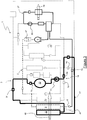
- the figure 1 shows a thermal conditioning device 1 according to the invention.
- the latter comprises a refrigerant fluid circuit 2, shown in broken lines, and a heat transfer fluid circuit 3, shown in solid lines.
- This thermal conditioning device 1 cooperates with a ventilation, heating and / or air conditioning system intended to modify the aerothermal parameters of the air contained or sent inside a vehicle cabin.
- the ventilation, heating and / or air conditioning system comprises a housing, made of plastic material, which houses a blower to circulate the air flow. interior from at least one air intake port to at least one air delivery port that includes the housing.
- a ventilation, heating and / or air conditioning system is housed for example under a dashboard of the vehicle and channels the circulation of the interior air flow.
- the thermal conditioning device 1 comprises the refrigerant circuit 2 inside which circulates a refrigerant fluid which provides calories (heating mode) or frigories (cooling mode), thus allowing the system to heat or cool the flow of water. indoor air.
- the refrigerant fluid circuit 2 may include one or more heat exchangers between the refrigerant fluid and either air or a heat transfer fluid circulating in the heat transfer fluid circuit 3, such a heat transfer fluid being for example l water comprising glycol.
- the refrigerant fluid present in the refrigerant fluid circuit 2 is for example of the type of a super-critical fluid, such as carbon dioxide, for example, known under the name R744. It can also be a subcritical fluid, such as hydrofluorocarbon, known under the term R134a, or a refrigerant with low impact on the greenhouse effect, that is to say which is in able to offer a sustainable solution for automotive air conditioners, known as HFO1234yf.
- the refrigerant fluid circuit 2 comprises at least one compressor 4 for compressing the refrigerant fluid in the gaseous state. It also comprises an external heat exchanger 5, able to function as a gas cooler or condenser or evaporator, the function of which is to ensure a heat exchange between the refrigerant fluid and an external air flow.
- a heat exchanger is termed exterior in the sense that it is installed at the level of a front part of the vehicle, so as to be exposed to the flow of exterior air set in motion in particular by the movement of the vehicle.
- the refrigerant fluid circuit 2 further comprises a member expansion device, hereinafter referred to as the first expansion member 6, installed between the compressor 4 and the external heat exchanger 5.
- a member expansion device hereinafter referred to as the first expansion member 6, installed between the compressor 4 and the external heat exchanger 5.
- Such a first expansion member 6 is used in particular when the refrigerant circuit 2 is operating in heating mode, as will be discussed in more detail in the description with reference to the figure 3 .
- the first expansion member 6 is installed on the refrigerant circuit 2 immediately upstream of the outdoor heat exchanger 5.
- the refrigerant fluid circuit 2 comprises an internal heat exchanger 7.
- an exchanger acts directly or indirectly on the temperature of the internal air flow. It is therefore one or more components capable of heating or cooling the internal air flow.
- the indoor heat exchanger 7 is an evaporator 8, the function of which is to capture calories in the indoor air flow when the system is operating in a cooling mode.
- an evaporator 8 performs a heat exchange directly between the refrigerant fluid and the internal air flow, the evaporator 8 comprising a bundle of tubes delimiting the chambers in which the refrigerant circulates and outside which the air flow. interior happening.
- the evaporator 8 is housed in the ventilation, heating and / or air conditioning installation. Depending on the cooling mode, the hot point of the refrigerant circuit is generated by the outdoor heat exchanger 5, while the cold point is generated by the evaporator 8.
- an additional internal heat exchanger 7 is a refrigerating fluid / heat transfer fluid exchanger, hereinafter referred to as a second refrigerant / heat transfer fluid exchanger 9, arranged to indirectly influence the temperature of the internal air flow.
- the second coolant / heat transfer fluid exchanger 9 transmits the calories present in the coolant to the heat transfer fluid so that the latter can transport them. up to an air heater, the latter forming one of the heat exchangers of the heat transfer fluid circuit 3.
- the thermal conditioning device 1 also comprises the heat transfer fluid circuit 3, the latter consisting of at least a first heat exchanger 10 associated with a component, a first circulation pump 11 for the heat transfer fluid, a first radiator 12 and a second radiator 13, these two radiators being for example separate.
- the first heat exchanger 10 is designed to capture the calories generated by a component of an electric traction chain of the vehicle.
- the first heat exchanger 10 therefore ensures cooling of this component, the latter possibly being for example a generator, that is to say an internal combustion engine coupled to an electric generator so as to create the electric energy used for set the electric vehicle in motion. It will be noted that the internal combustion engine of this generator set is however not used to generate a mechanical force in view of moving the vehicle.
- the first circulation pump 11 ensures the transport of the heat transfer fluid within the heat transfer fluid circuit 3.
- a first circulation pump 11 is for example an electric pump, that is to say comprising an electric motor.
- the first circulation pump 11 is installed in the heat transfer fluid circuit 3 directly downstream of the first heat exchanger 10.
- the first radiator 12 and the second radiator 13 are heat exchangers between, on the one hand the heat transfer fluid loaded with calories recovered for example at the level of the first heat exchanger 10, and on the other hand the flow of outside air which passes through the outdoor heat exchanger 5.
- the first radiator 12 and the second radiator 13 are installed at a front part of the vehicle, so as to be exposed to the exterior flow set in motion in particular by the movement of the vehicle.
- the external heat exchanger 5, the first radiator 12 and the second radiator 13 are arranged relative to each other in a particular manner. Indeed, these three exchangers are successively crossed by the flow of outside air, the outside heat exchanger 5 being interposed between the first radiator 12 and the second radiator 13. According to the direction of movement of the flow of outside air relative to at these three exchangers, the first radiator 12 is crossed by this flow of outside air first. Then, the outside air flow passes through the outside heat exchanger 5. Finally, this outside air flow passes through the second radiator 13.
- the thermal conditioning device 1 comprises means 14 for controlling the circulation of the heat transfer fluid in order to authorize or prohibit such circulation from the first heat exchanger 10, either exclusively to the first radiator 12, or exclusively to the second. radiator 13, or both to the first radiator 12 and to the second radiator 13.
- a control means 14 thus manages a circulation of the heat transfer fluid between the first heat exchanger 10 and the second radiator 13, and / or a circulation of the heat transfer fluid. heat transfer fluid between the first heat exchanger 10 and the first radiator 12, so as to heat the flow of outside air before it passes through the outside heat exchanger 5.
- the heat transfer fluid circuit 3 consists of at least three branches referenced 15, 16 and 17.
- the first branch 15 receives the first heat exchanger 10 and the first circulation pump 11.
- the second branch 16 receives for its part, the second radiator 13.
- the first branch 15 connected to the second branch 16 forms a closed loop of heat transfer fluid.
- the third branch 17 receives the first radiator 12.
- the control means 14 is installed at an intersection 20 of the first branch 15 with the second and the third branch.
- the third branch 17 is connected to the second branch 16 downstream of the second radiator 13, according to the direction of circulation of the heat transfer fluid when it passes through the latter. It is understood here that the heat transfer fluid which has passed through the first radiator 12 does not pass through the second radiator 13.
- control means 14 is formed by a three-way valve positioned at the intersection 20 of the first, second and third branches 15 to 17.
- a three-way valve thus comprises an inlet connected to the first branch 15. , a first outlet connected to the second branch 16 and a second outlet connected to the third branch 17.
- the control means 14 is formed by a first two-way valve 18 which allows or prohibits circulation of the heat transfer fluid from the first branch 15 to the third branch 17.
- a second two-way valve 19 is provided which allows or prohibits circulation of the heat transfer fluid from the first branch 15 to the second branch 16.
- the first two-way valve 18 is part of the third branch 17, and it is installed in the latter between the intersection 20 and the first radiator 12, in particular a coolant inlet for this radiator.
- the second two-way valve 19 is installed in the second branch 16 between the intersection 20 and the second radiator 13, for example between this intersection 20 and an inlet of this radiator.
- the thermal conditioning device 1 can comprise a heat transfer fluid circuit 3 in which heat exchangers have been added.
- a second heat exchanger 21 associated with an electric motor which moves the electric vehicle.
- Such a second heat exchanger 21 is for example installed in a fourth branch 22 constituting the heat transfer fluid circuit 3. It will be noted that this fourth branch is in parallel with the first, second and third branches 15 to 17.
- the heat transfer fluid circuit 3 can also include a third heat exchanger 23 associated with a battery which stores the electrical energy used in particular to set the vehicle in motion.
- This third heat exchanger 23 is installed in a fifth branch 24 of the heat transfer fluid circuit 3, this fifth branch 24 being in parallel with the first to fourth branches 15 to 17 and 22.
- This fifth branch 24 can also include a second circulation pump 25. coolant.
- the heat transfer fluid circuit 3 comprises a fourth heat exchanger 26 arranged to transfer calories present in the heat transfer fluid to the flow of interior air sent into the passenger compartment.
- This fourth exchanger 26 is in particular combined with the second refrigerant / heat transfer fluid exchanger 9, forming a first sub-circuit 27.
- a third circulation pump 28 is installed in this sub-circuit, as well as an electric heating radiator 52.
- This first sub-circuit 27 is connected to the heat transfer fluid circuit 3, being installed in parallel with the branches detailed above.
- the heat transfer fluid circuit 3 may comprise a fifth heat exchanger 31 associated with a vehicle braking device. It is also possible to provide a sixth heat exchanger 32 associated with a thermal storage device, in particular a latent heat storage device. This fifth heat exchanger 31 and this sixth heat exchanger 32 are installed in a sixth branch 51 installed in parallel with the first heat exchanger 10. In particular, the fifth heat exchanger 31 associated with the vehicle braking device is immediately upstream of the sixth heat exchanger. thermal 32 associated with the thermal storage device. It is thus possible to store a thermal surplus coming from the braking device in the storage device, and to use it at a time when there is a heating deficit on the heat transfer fluid circuit 3.
- the thermal conditioning device 1 may include one or more exchangers which provide heat exchange between the coolant and the coolant. Such exchangers are thus traversed both by the heat transfer fluid and by the refrigerant fluid.
- a first refrigerant / heat transfer fluid exchanger 29 arranged to influence the temperature of the third heat exchanger 23. This first refrigerant / heat transfer fluid exchanger 29 is thus combined with the third heat exchanger 23, as well as to the second heat transfer fluid circulation pump 25, to form a second sub-circuit 30, the latter being installed in the heat transfer fluid circuit 3 in a manner parallel to the branches and / or sub-circuit detailed above.
- the heat transfer fluid circuit 3 comprises the second coolant / heat transfer fluid exchanger 9, the latter being arranged to influence the temperature of the fourth heat exchanger 26 and thus heat the internal air flow, that is to say sent into the interior.
- the thermal conditioning device 1 can also comprise a plurality of devices for managing the circulation of the heat transfer fluid and of the refrigerant fluid.
- Such management devices are, for example, two-way valves or three-way valves capable of allowing or prohibiting circulation of fluid through them.
- a third two-way valve 33 installed in the first branch 15, in particular upstream of the first heat exchanger 10.
- the circulation of heat transfer fluid in the second branch 16 and / or in the third branch 17 is also placed under the control of a fourth two-way valve 34, placed downstream of the first and of the second radiator, and upstream of the first branch 15.
- the third branch 17 receives a fifth two-way valve 35 installed between the control means 14 and an inlet of the first radiator 12.
- a sixth two-way valve 36 is installed in the fifth branch 24, upstream of the third heat exchanger 23 assigned to the thermal conditioning of the battery. This sixth valve 36 allows or prohibits a circulation of heat transfer fluid from the fourth branch 22 to the second sub-circuit 30.
- a seventh two-way valve 37 is installed in the heat transfer fluid circuit so as to allow or prohibit circulation of heat transfer fluid to the first sub-circuit 27.
- sixth two-way valve 36 and the seventh two-way valve 37 can be replaced by a three-way valve.
- the first sub-circuit 27 also comprises an eighth two-way valve 38, for example installed upstream of the fourth heat exchanger 26.
- the seventh two-way valve 37 is closed, the first sub-circuit is isolated from the fourth branch 22.
- the third circulation pump 28 can thus implement a closed circuit circulation within the first subcircuit 27.
- the second sub-circuit 30 comprises a ninth two-way valve 39 whose function is to manage the circulation of heat transfer fluid between the first refrigerant / heat transfer fluid exchanger 29 and the third heat exchanger 23.
- a ninth two-way valve 39 is by example installed immediately upstream of the first refrigerant / heat transfer fluid exchanger 29.
- the second circulation pump 25 can thus implement closed-circuit circulation within the second subcircuit 30.
- the sixth branch 51 comprises a tenth two-way valve 50 which manages the circulation of the heat transfer fluid in the fifth and the sixth heat exchanger, respectively referenced 31 and 32. According to the embodiment of the figure 1 , this tenth two-way valve 50 is immediately upstream of the fifth heat exchanger 31.
- the device (s) for managing the circulation of refrigerant fluid take the form of a first two-way valve 40 installed downstream of the second refrigerant / heat transfer fluid exchanger 9 and upstream of the refrigerant / heat transfer fluid.
- first expansion member 6 comprises a bypass pipe 41 whose function is to allow the first expansion member to be bypassed when the external heat exchanger 5 is used as a condenser, that is to say. say during a cooling mode of the interior air flow, in particular.
- a second two-way valve 42 manages the circulation of refrigerant fluid to the evaporator 8.
- This second two-way valve 42 is thus installed in the refrigerant circuit 2 between the second refrigerant / heat transfer fluid exchanger 9 and a second expansion member. 43, the latter being immediately upstream of the evaporator 8.
- the refrigerant fluid circuit 2 Downstream from the outdoor heat exchanger 5, the refrigerant fluid circuit 2 comprises a third two-way valve 44.
- a non-return valve 45 is also provided, installed in a portion of the refrigerant circuit located in parallel with the. external heat exchanger 5 and connected to the first exchanger 29 refrigerant / heat transfer fluid.
- This portion of the circuit which supplies this first refrigerant / heat transfer fluid exchanger 29 further comprises a third expansion member 46 installed downstream of the non-return valve 45, and immediately upstream of the first refrigerant / heat transfer fluid exchanger 29.
- the refrigerant fluid circuit 2 also comprises a device for storing the refrigerant fluid. According to an exemplary embodiment, this takes the form of an accumulator 47 installed immediately upstream of the electric compressor 4.
- the phantom lines represent the parts of the refrigerant circuit 2 in which circulates a refrigerant fluid at low pressure, compared to the strong lines which represent the parts of this same circuit in which this same fluid at high pressure circulates, that is to say - say a value of pressure higher than the value of the low pressure of the fluid.
- the thin interrupted lines illustrate the portions of the refrigerant circuit which are not taken by the refrigerant during the operating mode considered.
- the figure 2 shows an operating mode of the passenger compartment cooling and generator set cooling type.
- the pressure and the temperature of the refrigerant fluid are raised by the compressor 4.
- the refrigerant in this high pressure state, passes through the second exchanger 9 refrigerant / heat transfer fluid, for example without qu no heat exchange is carried out between the refrigerant fluid present in the second refrigerant / heat transfer fluid exchanger 9 and the heat transfer fluid present in the first subcircuit 27.
- the third circulation pump 28 is inactive.
- the first two-way valve 40 is open, while the second two-way valve 42 is closed.
- the refrigerant therefore continues its path in the direction of the first expansion member 6.
- the refrigerant is not expanded by the latter, and it passes through the bypass pipe 41 to join the external heat exchanger 5.
- the refrigerant fluid transfers calories to the external air flow, here referenced 48.
- the third two-way valve 44 is closed, which forces the refrigerant fluid to circulate through the non-return valve. 45.
- the third expansion member 46 is placed in a closed position while the second expansion member 43 is placed in a position where it implements an expansion of the refrigerant fluid.
- the refrigerant thus expanded passes through the evaporator 8 and captures the calories present in the interior air flow, referenced here 49. This ensures the cooling of the vehicle interior.
- the refrigerant fluid returns to the compressor 4 by passing through the accumulator 47.
- the first circulation pump 11 is activated.
- the second two-way valve 19 is open, while the first two-way valve 18 is closed.
- the heat transfer fluid enters the second radiator 13, the latter operating a heat exchange between this heat transfer fluid and the outside air flow 48 so as to cool the heat transfer fluid.
- the fourth two-way valve 34 is placed in the open position, while the sixth two-way valve 36, the seventh two-way valve 37 and the tenth two-way valve 50 are closed.
- the heat transfer fluid then passes through the first heat exchanger 10, the third two-way valve 33 being open.
- the generator set is thus cooled by the heat transfer fluid which passes through its dedicated heat exchanger, that is to say the first heat exchanger 10. After passing through this, the heat transfer fluid returns to the first circulation pump 11.
- the figure 3 illustrates an operating mode corresponding to heating the passenger compartment of the vehicle from calories generated by the refrigerant circuit 2. This operating mode presents a risk of icing of the external heat exchanger 5.
- the pressure and the temperature of the refrigerant fluid are raised by the compressor 4.
- the refrigerant fluid in this high pressure state, passes through the second refrigerant / heat transfer fluid exchanger 9, and gives up its calories to the heat transfer fluid.
- heat transfer fluid which circulates in the first sub-circuit 27, such circulation being operated by an activation of the third circulation pump 28.
- the first two-way valve 40 is open, while the second two-way valve 42 is closed.
- the refrigerant therefore continues its path in the direction of the first expansion member 6 where it undergoes a lowering of its pressure. In this situation, the refrigerant does not take the bypass pipe 41.
- the refrigerant thus expanded then passes through the external heat exchanger 5, which results in cooling of the external air flow 48.
- the third two-way valve 44 is open, which allows the refrigerant fluid to reach the compressor 4 via the accumulator 47.
- the outdoor heat exchanger 5 functions here as an evaporator. According to the invention, the risk of icing of this external heat exchanger 5 is avoided by the control means 14 combined at the disposal of the two radiators and of the external heat exchanger. This is how the second two-way valve 19 is placed in the closed position, thus preventing any circulation of heat transfer fluid to the second radiator 13.
- the second two-way valve 18 and the fifth two-way valve 35 are placed in the open position so as to allow circulation of the heat transfer fluid from the first branch 15 to the third branch 17 containing the first radiator 12, such circulation being implemented. by activating the first circulation pump 11.
- the coolant heated by the first heat exchanger 10, transfers its calories to the flow of outside air 48 via the first radiator 12.
- the latter is placed upstream of the outside heat exchanger 5, in the direction of displacement of the flow of outside air 45. This flow of outside air thus heated generates a temperature difference which prevents any icing phenomenon on the outside heat exchanger 5.
- the heat transfer fluid then joins the fourth two-way valve 34 and continues its return to the first heat exchanger 10.
- the first expansion member 6, the second expansion member 43 and / or the third expansion member 46 are formed, in particular, each by a thermostatic expansion member, a calibrated orifice or an electronic expansion valve. controlled by a management strategy implemented by a control system.
Description
Le secteur technique de la présente invention est celui des ensembles ou systèmes utilisés pour conditionner au moins un flux d'air entrant dans un habitacle de véhicule automobile. Selon l'invention, un tel système assure également le conditionnement thermique de composants constitutifs d'une chaîne électrique de traction de ce véhicule. Plus particulièrement, l'invention vise un circuit de fluide réfrigérant combiné à un circuit de fluide caloporteur, où le circuit de fluide réfrigérant est utilisé en mode chauffage, autrement appelé pompe à chaleur. Pendant cette phase de fonctionnement, le circuit de fluide caloporteur est agencé et piloté pour dégivrer un échangeur du circuit de fluide réfrigérant.The technical sector of the present invention is that of assemblies or systems used to condition at least one flow of air entering a passenger compartment of a motor vehicle. According to the invention, such a system also ensures the thermal conditioning of components constituting an electric traction chain of this vehicle. More particularly, the invention relates to a refrigerant fluid circuit combined with a heat transfer fluid circuit, where the refrigerant fluid circuit is used in heating mode, otherwise called a heat pump. During this operating phase, the heat transfer fluid circuit is arranged and controlled to defrost an exchanger of the refrigerant fluid circuit.
Un véhicule automobile est classiquement équipé d'une boucle de climatisation à l'intérieur de laquelle circule un fluide frigorigène. Cette boucle comprend un compresseur, un condenseur, un détendeur et un évaporateur parcourus par le fluide frigorigène. L'évaporateur est monté dans une installation de ventilation, chauffage et/ou climatisation généralement montée dans l'habitacle du véhicule, pour fournir à ce dernier un flux d'air chaud ou un flux d'air froid en fonction d'une demande de l'utilisateur du véhicule. Le condenseur est quant à lui classiquement installé en face avant du véhicule pour être traversé par un flux d'air extérieur au véhicule.A motor vehicle is conventionally equipped with an air conditioning loop inside which a refrigerant circulates. This loop includes a compressor, a condenser, an expansion valve and an evaporator through which the refrigerant flows. The evaporator is mounted in a ventilation, heating and / or air conditioning installation generally mounted in the passenger compartment of the vehicle, to provide the latter with a flow of hot air or a flow of cold air according to a demand for the vehicle user. The condenser is for its part conventionally installed on the front face of the vehicle to be traversed by a flow of air outside the vehicle.
Cette boucle de climatisation peut être utilisée en mode refroidissement ou en mode chauffage. En mode refroidissement, le fluide réfrigérant est envoyé vers le condenseur où il est refroidi par le flux d'air extérieur. Puis, le fluide réfrigérant circule vers le détendeur où il subit un abaissement de sa pression avant d'entrer dans l'évaporateur. Le fluide réfrigérant traversant l'évaporateur est alors chauffé par le flux d'air entrant dans l'installation de ventilation, ce qui se traduit corrélativement par un refroidissement de ce flux d'air dans le but de climatiser l'habitacle du véhicule. Le circuit étant une boucle fermée, le fluide réfrigérant retourne alors vers le compresseur.This air conditioning loop can be used in cooling mode or in heating mode. In cooling mode, the refrigerant is sent to the condenser where it is cooled by the flow of outside air. Then, the refrigerant fluid circulates to the expansion valve where it undergoes a drop in its pressure before entering the evaporator. The refrigerant fluid passing through the evaporator is then heated by the flow of air entering the ventilation installation, which correlates with cooling of this flow of air for the purpose of air conditioning the passenger compartment of the vehicle. The circuit being a closed loop, the refrigerant then returns to the compressor.
En mode chauffage, le fluide est mis en circulation par le compresseur qui l'envoie vers l'évaporateur. Ce dernier se comporte alors comme un condenseur, où le fluide réfrigérant est refroidi par l'air circulant dans l'installation de ventilation. Cet air se chauffe donc au contact de l'évaporateur et apporte ainsi des calories à l'habitacle du véhicule. Après passage dans l'évaporateur, le fluide réfrigérant est détendu par un détendeur avant d'arriver dans le condenseur. Le flux d'air extérieur chauffe alors le fluide réfrigérant. Le flux d'air extérieur est par conséquent plus froid après son passage dans le condenseur comparé à sa température avant son passage au travers du condenseur. Le fluide réfrigérant retourne alors vers le compresseur.In heating mode, the fluid is circulated by the compressor which sends it to the evaporator. The latter then behaves like a condenser, where the refrigerant is cooled by the air circulating in the ventilation installation. This air is therefore heated on contact with the evaporator and thus provides heat to the vehicle interior. After passing through the evaporator, the refrigerant is expanded by an expansion valve before arriving in the condenser. The flow of outside air then heats the refrigerant. The outdoor air flow is therefore cooler after passing through the condenser compared to its temperature before passing through the condenser. The refrigerant then returns to the compressor.
En mode chauffage, le condenseur installé à l'extérieur de l'habitacle se comporte comme un évaporateur. Autrement dit, au cours du cheminement du fluide réfrigérant à l'intérieur du condenseur, le fluide réfrigérant capte de la chaleur au flux d'air ambiant. Dans ce dernier mode, il est des conditions climatiques au cours desquelles se forme du givre sur le condenseur utilisé en tant qu'évaporateur. Ceci est le résultat du refroidissement opéré par le condenseur, fonctionnant en tant qu'évaporateur, qui abaisse la température du flux d'air ambiant le traversant en dessous de zéro degré Celsius, provoquant ainsi un gel de l'humidité présente dans le flux d'air ambiant. Cette situation est problématique car le givre obstrue le passage du flux d'air ambiant au travers du condenseur, ce qui dégrade fortement les performances de la boucle de climatisation en mode chauffage au point de ne plus assurer la fonction de chauffage du flux d'air envoyé dans l'habitacle. Il en découle finalement une diminution des performances thermiques de la boucle de climatisation, ce qu'il convient d'éviter.In heating mode, the condenser installed outside the passenger compartment behaves like an evaporator. In other words, during the flow of the refrigerant fluid inside the condenser, the refrigerant fluid picks up heat from the ambient air flow. In the latter mode, there are climatic conditions during which frost forms on the condenser used as an evaporator. This is the result of the cooling operated by the condenser, functioning as an evaporator, which lowers the temperature of the ambient air flow passing through it below zero degrees Celsius, thus causing the humidity present in the flow to freeze. 'ambiant air. This situation is problematic because the frost obstructs the passage of the ambient air flow through the condenser, which greatly degrades the performance of the air conditioning loop in heating mode to the point of no longer ensuring the heating function of the air flow. sent into the cockpit. This ultimately results in a decrease in the thermal performance of the air conditioning loop, which should be avoided.
L'état de l'art est représenté dans les documents
Le but de la présente invention est donc de résoudre l'inconvénient décrit ci-dessus principalement en opérant un chauffage préalable de l'air ambiant avant que celui-ci ne traverse l'échangeur extérieur, quand celui-ci est utilisé en tant qu'évaporateur.
L'invention a donc pour objet un dispositif ou ensemble de conditionnement thermique selon la revendication 1.The aim of the present invention is therefore to resolve the drawback described above mainly by carrying out a preliminary heating of the ambient air before the latter passes through the external exchanger, when the latter is used as a evaporator.
The subject of the invention is therefore a thermal conditioning device or assembly according to
Selon un exemple de réalisation alternatif, le moyen de contrôle est une vanne trois voies installée au droit de l'intersection.According to an alternative embodiment, the control means is a three-way valve installed at the right of the intersection.
Dans le dispositif selon l'invention, la première vanne deux voies a pour fonction d'autoriser ou d'interdire une circulation du fluide caloporteur vers le premier radiateur. Il en va de même pour la deuxième vanne deux voies à l'égard du deuxième radiateur.In the device according to the invention, the first two-way valve has the function of authorizing or prohibiting circulation of the heat transfer fluid towards the first radiator. The same applies to the second two-way valve with respect to the second radiator.
La première vanne deux voies est installée dans la troisième branche entre l'intersection et le premier radiateur, alors que la deuxième vanne deux voies est installée dans la deuxième branche entre l'intersection et le deuxième radiateur.The first two-way valve is installed in the third branch between the intersection and the first radiator, while the second two-way valve is installed in the second branch between the intersection and the second radiator.
Selon un mode de réalisation, la troisième branche est raccordée à la deuxième branche en aval du deuxième radiateur. Le fluide caloporteur ayant traversé le premier radiateur rejoint ainsi le circuit de fluide caloporteur sans traverser le deuxième radiateur.According to one embodiment, the third branch is connected to the second branch downstream of the second radiator. The heat transfer fluid having passed through the first radiator thus joins the heat transfer fluid circuit without passing through the second radiator.
Selon une caractéristique de l'invention, la première branche reçoit la première pompe de circulation. Une telle pompe est avantageusement une pompe électrique.According to one characteristic of the invention, the first branch receives the first circulation pump. Such a pump is advantageously an electric pump.
On notera que la première pompe de circulation est apte à mettre en circulation le fluide caloporteur dans la première branche, dans la deuxième branche et/ou dans la troisième branche.It will be noted that the first circulation pump is able to circulate the heat transfer fluid in the first branch, in the second branch and / or in the third branch.
L'invention concerne également une chaîne électrique de traction d'un véhicule électrique comprenant un dispositif de conditionnement thermique tel que présenté ci-dessus.The invention also relates to an electric traction chain of an electric vehicle comprising a thermal conditioning device as presented above.
Dans une telle chaîne, au moins un moteur électrique génère le déplacement du véhicule électrique, la chaîne électrique de traction comprenant une batterie et un groupe électrogène qui forme le composant associé au premier échangeur thermique.In such a chain, at least one electric motor generates the movement of the electric vehicle, the electric traction chain comprising a battery and a generator which forms the component associated with the first heat exchanger.
Selon un exemple de réalisation de cette chaîne, le circuit de fluide caloporteur peut comprendre :
- un deuxième échangeur thermique associé au moteur électrique,
- un troisième échangeur thermique associé à la batterie,
- un quatrième échangeur thermique apte à chauffer un flux d'air intérieur envoyé dans un habitacle du véhicule.
- a second heat exchanger associated with the electric motor,
- a third heat exchanger associated with the battery,
- a fourth heat exchanger capable of heating an interior air flow sent into a passenger compartment of the vehicle.
Dans un exemple de chaîne selon l'invention, le circuit de fluide réfrigérant comprend un premier échangeur fluide réfrigérant/fluide caloporteur agencé pour influencer la température du troisième échangeur thermique, un deuxième échangeur fluide réfrigérant/fluide caloporteur agencé pour influencer la température du quatrième échangeur thermique, l'échangeur intérieur étant traversé par le flux d'air intérieur et forme un évaporateur.In an example of a chain according to the invention, the refrigerant fluid circuit comprises a first refrigerant / heat transfer fluid exchanger arranged to influence the temperature of the third heat exchanger, a second refrigerant / heat transfer fluid exchanger arranged to influence the temperature of the fourth heat exchanger thermal, the internal exchanger being crossed by the internal air flow and forms an evaporator.
Selon un exemple complémentaire ou alternatif, la chaîne peut comprendre le circuit de fluide caloporteur dans lequel un échangeur thermique est associé à un dispositif de freinage du véhicule, et/ou un échangeur thermique associé à un dispositif de stockage thermique.According to a complementary or alternative example, the chain can comprise the heat transfer fluid circuit in which a heat exchanger is associated with a vehicle braking device, and / or a heat exchanger associated with a thermal storage device.
L'association échangeur thermique - composant évoqué ci-dessus signifie que l'échangeur thermique est dédié au chauffage et/ou au refroidissement du composant considéré. Selon un exemple de réalisation, l'échangeur thermique est en contact physique avec le composant.The association of heat exchanger - component mentioned above means that the heat exchanger is dedicated to heating and / or cooling of the component considered. According to an exemplary embodiment, the heat exchanger is in physical contact with the component.
Un tout premier avantage selon l'invention réside dans la possibilité de dégivrer aisément l'échangeur thermique installé au niveau de la face avant du véhicule. Le fluide caloporteur est agencé pour capter des calories en un ou plusieurs points de la chaîne électrique de traction, de manière à les transférer au flux d'air extérieur avant que ce dernier ne traverse l'échangeur extérieur constitutif du circuit de fluide réfrigérant. On évite ainsi toute dégradation de la fonction de chauffage de l'habitacle, puisque la différence entre la température du flux d'air extérieur et la température du fluide réfrigérant qui traverse l'échangeur extérieur est volontairement augmentée par l'agencement proposé dans la revendication principale.A very first advantage according to the invention lies in the possibility of easily defrosting the heat exchanger installed at the front of the vehicle. The heat transfer fluid is arranged to capture calories at one or more points of the electric traction chain, so as to transfer them to the flow of outside air before the latter passes through the outside exchanger constituting the refrigerant circuit. This avoids any degradation of the function of heating the passenger compartment, since the difference between the temperature of the flow of outside air and the temperature of the refrigerant fluid which passes through the outside exchanger is intentionally increased by the arrangement proposed in the main claim.
D'autres caractéristiques, détails et avantages de l'invention ressortiront plus clairement à la lecture de la description donnée ci-après à titre indicatif en relation avec des dessins dans lesquels :
- la
figure 1 est une vue schématique illustrant les composants constitutifs d'un exemple de réalisation du dispositif selon l'invention, en l'absence de circulation des fluides, - la
figure 2 est une vue schématique illustrant le dispositif selon l'invention en un premier mode de fonctionnement, - la
figure 3 est une vue schématique illustrant le dispositif selon l'invention en un deuxième mode de fonctionnement.
- the
figure 1 is a schematic view illustrating the constituent components of an exemplary embodiment of the device according to the invention, in the absence of circulation of fluids, - the
figure 2 is a schematic view illustrating the device according to the invention in a first operating mode, - the
figure 3 is a schematic view illustrating the device according to the invention in a second operating mode.
Dans la description ci-dessous, les termes amont et aval sont utilisés. Par convention, ces termes s'analysent au regard du composant concerné, par rapport au sens du fluide dans le circuit concerné et selon le mode de fonctionnement envisagé.In the description below, the terms upstream and downstream are used. By convention, these terms are analyzed with regard to the component concerned, with respect to the direction of the fluid in the circuit concerned and according to the mode of operation envisaged.
La
Une telle modification est obtenue à partir de la délivrance d'au moins un flux d'air pulsé à l'intérieur de l'habitacle, ci-après appelé flux d'air intérieur. A cet effet, le système de ventilation, de chauffage et/ou de climatisation comprend un boîtier, réalisé en matière plastique, qui loge un pulseur pour faire circuler le flux d'air intérieur depuis au moins une bouche d'admission d'air vers au moins une bouche de délivrance d'air que comporte le boîtier. Un tel système de ventilation, de chauffage et/ou de climatisation est logé par exemple sous une planche de bord du véhicule et canalise la circulation du flux d'air intérieur.Such a modification is obtained from the delivery of at least one flow of pulsed air inside the passenger compartment, hereinafter called the flow of interior air. To this end, the ventilation, heating and / or air conditioning system comprises a housing, made of plastic material, which houses a blower to circulate the air flow. interior from at least one air intake port to at least one air delivery port that includes the housing. Such a ventilation, heating and / or air conditioning system is housed for example under a dashboard of the vehicle and channels the circulation of the interior air flow.
Le dispositif de conditionnement thermique 1 comprend le circuit de fluide réfrigérant 2 à l'intérieur duquel circule un fluide réfrigérant qui apporte des calories (mode chauffage) ou des frigories (mode refroidissement), permettant ainsi au système de chauffer ou de refroidir le flux d'air intérieur.The
Pour ce faire, le circuit de fluide réfrigérant 2 peut comporter un ou plusieurs échangeurs thermiques entre le fluide réfrigérant et soit de l'air, soit un fluide caloporteur circulant dans le circuit de fluide caloporteur 3, un tel fluide caloporteur étant par exemple de l'eau comportant du glycol.To do this, the
Le fluide réfrigérant présent dans le circuit de fluide réfrigérant 2 est par exemple du type d'un fluide super-critique, tel que du dioxyde de carbone, par exemple, connu sous l'appellation R744. Il peut aussi s'agir d'un fluide sous-critique, tel que l'hydrofluorocarbone, connu sous le terme R134a, ou un fluide frigorigène à faible impact sur l'effet de serre, c'est-à-dire qui soit en mesure d'offrir une solution durable pour les climatiseurs automobiles, connu sous la dénomination HFO1234yf.The refrigerant fluid present in the
Le circuit de fluide réfrigérant 2 comprend au moins un compresseur 4 pour comprimer le fluide réfrigérant à l'état gazeux. Il comprend aussi un échangeur de chaleur extérieur 5, apte à fonctionner en tant que refroidisseur de gaz ou condenseur ou évaporateur, dont la fonction est d'assurer un échange thermique entre le fluide réfrigérant et un flux d'air extérieur. Un tel échangeur de chaleur est qualifié d'extérieur en ce sens qu'il est installé au niveau d'une partie frontale du véhicule, de manière à être exposé au flux d'air extérieur mis en mouvement notamment par le déplacement du véhicule.The
Selon l'invention, le circuit de fluide réfrigérant 2 comprend encore un organe de détente, ci-après appelé premier organe de détente 6, installé entre le compresseur 4 et l'échangeur de chaleur extérieur 5. Un tel premier organe de détente 6 est notamment utilisé lorsque le circuit de fluide réfrigérant 2 fonctionne en mode de chauffage, comme cela sera abordé plus en détails à la description en référence à la
Selon l'exemple illustré sur la
Toujours selon l'invention, le circuit de fluide réfrigérant 2 comprend un échangeur de chaleur intérieur 7. D'une manière générale, un tel échangeur agit directement ou indirectement sur la température du flux d'air intérieur. Il s'agit donc d'un ou plusieurs composants aptes à chauffer ou refroidir le flux d'air intérieur.Still according to the invention, the
L'échangeur de chaleur intérieur 7 est un évaporateur 8, dont la fonction est de capter des calories dans le flux d'air intérieur quand le système fonctionne en un mode de refroidissement. Un tel évaporateur 8 réalise un échange thermique directement entre le fluide réfrigérant et le flux d'air intérieur, l'évaporateur 8 comprenant un faisceau de tubes délimitant des chambres dans lesquelles circule le fluide réfrigérant et à l'extérieur desquelles le flux d'air intérieur passe. L'évaporateur 8 est logé dans l'installation de ventilation, de chauffage et/ou de climatisation. Selon le mode de refroidissement, le point chaud du circuit de fluide réfrigérant est généré par l'échangeur de chaleur extérieur 5, alors que le point froid est généré par l'évaporateur 8.The
Selon l'invention, un échangeur complémentaire de chaleur intérieur 7 est un échangeur fluide réfrigérant/fluide caloporteur, ci-après appelé deuxième échangeur 9 fluide réfrigérant/fluide caloporteur, agencé pour influencer indirectement la température du flux d'air intérieur. Le deuxième échangeur 9 fluide réfrigérant/fluide caloporteur assure une transmission des calories présentes dans le fluide réfrigérant au fluide caloporteur pour que celui-ci les transportent jusqu'à un aérotherme, ce dernier formant un des échangeurs thermiques du circuit de fluide caloporteur 3.According to the invention, an additional
Le dispositif de conditionnement thermique 1 selon l'invention comprend encore le circuit de fluide caloporteur 3, ce dernier étant constitué d'au moins un premier échangeur thermique 10 associé à un composant, une première pompe de circulation 11 du fluide caloporteur, un premier radiateur 12 et un deuxième radiateur 13, ces deux radiateurs étant par exemple distincts.The
Le premier échangeur thermique 10 est agencé pour capter des calories générées par un composant d'une chaîne électrique de traction du véhicule. Le premier échangeur thermique 10 assure donc un refroidissement de ce composant, ce dernier pouvant être par exemple un groupe électrogène, c'est-à-dire un moteur à combustion interne couplé à un générateur électrique de manière à créer l'énergie électrique utilisée pour mettre en mouvement le véhicule électrique. On notera que le moteur à combustion interne de ce groupe électrogène n'est en revanche pas utilisé pour générer une force mécanique en vu de déplacer le véhicule.The
La première pompe de circulation 11 assure le transport du fluide caloporteur au sein du circuit de fluide caloporteur 3. Selon un exemple, une telle première pompe de circulation 11 est par exemple une pompe électrique, c'est-à-dire comprenant un moteur électrique. La première pompe de circulation 11 est installée dans le circuit de fluide caloporteur 3 directement en aval du premier échangeur thermique 10.The
Le premier radiateur 12 et le deuxième radiateur 13 sont des échangeurs de chaleur entre, d'une part le fluide caloporteur chargé de calories récupérées par exemple au niveau du premier échangeur thermique 10, et d'autre part le flux d'air extérieur qui traverse l'échangeur de chaleur extérieur 5.The
Comme l'échangeur de chaleur extérieur 5, le premier radiateur 12 et le deuxième radiateur 13 sont installés au niveau d'une partie frontale du véhicule, de manière à être exposés au flux d'extérieur mis en mouvement notamment par le déplacement du véhicule.Like the external heat exchanger 5, the
Selon l'invention, l'échangeur de chaleur extérieur 5, le premier radiateur 12 et le deuxième radiateur 13 sont disposés les uns par rapport aux autres de manière particulière. En effet, ces trois échangeurs sont successivement traversés par le flux d'air extérieur, l'échangeur de chaleur extérieur 5 étant interposé entre le premier radiateur 12 et le deuxième radiateur 13. Selon le sens de déplacement du flux d'air extérieur par rapport à ces trois échangeurs, le premier radiateur 12 est traversé par ce flux d'air extérieur en premier. Puis, le flux d'air extérieur traverse l'échangeur de chaleur extérieur 5. Enfin, ce flux d'air extérieur traverse le deuxième radiateur 13.According to the invention, the external heat exchanger 5, the
Selon l'invention, le dispositif de conditionnement thermique 1 comprend un moyen de contrôle 14 de la circulation du fluide caloporteur pour autoriser ou interdire une telle circulation depuis le premier échangeur thermique 10, soit exclusivement vers le premier radiateur 12, soit exclusivement vers le deuxième radiateur 13, soit à la fois vers le premier radiateur 12 et vers le deuxième radiateur 13. Un tel moyen de contrôle 14 gère ainsi une circulation du fluide caloporteur entre le premier échangeur thermique 10 et le deuxième radiateur 13, et/ou une circulation du fluide caloporteur entre le premier échangeur thermique 10 et le premier radiateur 12, de manière à chauffer le flux d'air extérieur préalablement à sa traversée de l'échangeur de chaleur extérieur 5.According to the invention, the
Selon un exemple de réalisation, le circuit de fluide caloporteur 3 est constitué d'au mois trois branches référencées 15, 16 et 17. La première branche 15 reçoit le premier échangeur thermique 10 et la première pompe de circulation 11. La deuxième branche 16 reçoit quant à elle le deuxième radiateur 13. La première branche 15 connectée à la deuxième branche 16 forment une boucle fermée de fluide caloporteur. En parallèle de la deuxième branche 16, la troisième branche 17 reçoit le premier radiateur 12. Le moyen de contrôle 14 est installé à une intersection 20 de la première branche 15 avec la deuxième et la troisième branche. On notera enfin que la troisième branche 17 est raccordée à la deuxième branche 16 en aval du deuxième radiateur 13, selon le sens de circulation du fluide caloporteur quand il traverse ce dernier. On comprend ici que le fluide caloporteur ayant traversé le premier radiateur 12 ne traverse pas le deuxième radiateur 13.According to an exemplary embodiment, the heat
Selon un exemple non représenté, le moyen de contrôle 14 est formé par une vanne trois voies positionnée à l'intersection 20 des première, deuxième et troisième branches 15 à 17. Une telle vanne trois voies comprend ainsi une entrée raccordée à la première branche 15, une première sortie raccordée à la deuxième branche 16 et une deuxième sortie raccordée à la troisième branche 17.According to an example not shown, the control means 14 is formed by a three-way valve positioned at the
Selon l'exemple illustrée par la
De manière optionnelle mais néanmoins intéressante, le dispositif de conditionnement thermique 1 peut comprendre un circuit de fluide caloporteur 3 dans lequel des échangeurs thermiques ont été ajoutés. Il est ainsi prévu un deuxième échangeur thermique 21 associé à un moteur électrique qui assure le déplacement du véhicule électrique. Un tel deuxième échangeur thermique 21 est par exemple installé dans une quatrième branche 22 constitutive du circuit de fluide caloporteur 3. On notera que cette quatrième branche est en parallèle des première, deuxième et troisième branches 15 à 17.Optionally but nevertheless interesting, the
Le circuit de fluide caloporteur 3 peut également comporter un troisième échangeur thermique 23 associé à une batterie qui assure un stockage de l'énergie électrique utilisée notamment pour mettre en mouvement le véhicule. Ce troisième échangeur thermique 23 est installé dans une cinquième branche 24 du circuit de fluide caloporteur 3, cette cinquième branche 24 étant en parallèle des première à quatrième branches 15 à 17 et 22. Cette cinquième branche 24 peut également comprendre une deuxième pompe de circulation 25 du fluide caloporteur.The heat
Le circuit de fluide caloporteur 3 comprend un quatrième échangeur thermique 26 agencé pour transférer des calories présentes dans le fluide caloporteur au flux d'air intérieur envoyé dans l'habitacle. Ce quatrième échangeur 26 est notamment combiné au deuxième échangeur 9 fluide réfrigérant/fluide caloporteur en formant un premier sous-circuit 27. Une troisième pompe de circulation 28 est installée dans ce sous-circuit, ainsi qu'un radiateur électrique de chauffage 52. Ce premier sous-circuit 27 est raccordé au circuit de fluide caloporteur 3, en étant installé en parallèle des branches détaillés plus haut.The heat
Selon l'exemple de réalisation, le circuit de fluide caloporteur 3 peut comprendre un cinquième échangeur thermique 31 associé à un dispositif de freinage du véhicule. Il est également possible de prévoir un sixième échangeur thermique 32 associé à un dispositif de stockage thermique, notamment un dispositif de stockage à chaleur latente. Ce cinquième échangeur thermique 31 et ce sixième échangeur thermique 32 sont installés dans une sixième branche 51 installée en parallèle du premier échangeur thermique 10. De manière particulière, le cinquième échangeur thermique 31 associé au dispositif de freinage du véhicule est immédiatement en amont du sixième échangeur thermique 32 associé au dispositif de stockage thermique. Il est ainsi possible de stocker un surplus thermique provenant du dispositif de freinage dans le dispositif de stockage, et de l'utiliser à un moment où il existe un déficit de chauffage sur le circuit de fluide caloporteur 3.According to the exemplary embodiment, the heat
Toujours de manière optionnelle, le dispositif de conditionnement thermique 1 peut comporter un ou plusieurs échangeurs qui assurent un échange thermique entre le fluide caloporteur et le fluide réfrigérant. De tels échangeurs sont ainsi traversés à la fois par le fluide caloporteur et par le fluide réfrigérant. Selon un exemple de réalisation, il est prévu un premier échangeur 29 fluide réfrigérant/fluide caloporteur agencé pour influencer la température du troisième échangeur thermique 23. Ce premier échangeur 29 fluide réfrigérant/fluide caloporteur est ainsi combiné au troisième échangeur thermique 23, ainsi qu'à la deuxième pompe de circulation 25 de fluide caloporteur, pour former un deuxième sous-circuit 30, ce dernier étant installé dans le circuit de fluide caloporteur 3 de manière parallèle aux branches et/ou sous-circuit détaillées ci-dessus.Still optionally, the
Le circuit de fluide caloporteur 3 comprend le deuxième échangeur 9 fluide réfrigérant/fluide caloporteur, ce dernier étant agencé pour influencer la température du quatrième échangeur thermique 26 et ainsi chauffer le flux d'air intérieur, c'est-à-dire envoyé dans l'habitacle.The heat
Le dispositif de conditionnement thermique 1 peut encore comprendre une pluralité de dispositifs de gestion de la circulation du fluide caloporteur et du fluide réfrigérant. De tels dispositif de gestion sont par exemple des vannes deux voies ou des vannes trois voies apte à autoriser ou interdire une circulation de fluide à leurs travers.The
En ce qui concerne le circuit de fluide caloporteur 3, il est prévu une troisième vanne deux voies 33 installé dans la première branche 15, notamment en amont du premier échangeur thermique 10. La circulation de fluide caloporteur dans la deuxième branche 16 et/ou dans la troisième branche 17 est également placée sous la dépendance d'une quatrième vanne deux voies 34, placée en aval du premier et du deuxième radiateur, et en amont de la première branche 15.With regard to the heat
La troisième branche 17 reçoit une cinquième vanne deux voies 35 installée entre le moyen de contrôle 14 et une entrée du premier radiateur 12.The
Une sixième vanne deux voies 36 est installée dans la cinquième branche 24, en amont du troisième échangeur thermique 23 affecté au conditionnement thermique de la batterie. Cette sixième vanne 36 autorise ou interdit une circulation de fluide caloporteur depuis la quatrième branche 22 vers le deuxième sous-circuit 30.A sixth two-
Une septième vanne deux voies 37 est installée dans le circuit de fluide caloporteur de manière à autoriser ou interdire une circulation de fluide caloporteur vers le premier sous-circuit 27.A seventh two-
On notera que la sixième vanne deux voies 36 et la septième vanne deux voies 37 peuvent être remplacées par une vanne trois voies.It will be noted that the sixth two-
Le premier sous-circuit 27 comprend également une huitième vanne deux voies 38, par exemple installée en amont du quatrième échangeur thermique 26. Lorsque la septième vanne deux voies 37 est fermée, le premier sous-circuit est isolé de la quatrième branche 22. La troisième pompe de circulation 28 peut ainsi mettre en œuvre une circulation en circuit fermé au sein du premier sous-circuit 27.The first sub-circuit 27 also comprises an eighth two-
Le deuxième sous-circuit 30 comprend une neuvième vanne deux voies 39 dont la fonction est de gérer la circulation de fluide caloporteur entre le premier échangeur 29 fluide réfrigérant/fluide caloporteur et le troisième échangeur thermique 23. Une telle neuvième vanne deux voies 39 est par exemple installée immédiatement en amont du premier échangeur 29 fluide réfrigérant/fluide caloporteur. Lorsque la sixième vanne deux voies 36 est fermée, le deuxième sous-circuit est isolé de la quatrième branche 22. La deuxième pompe de circulation 25 peut ainsi mettre en œuvre une circulation en circuit fermé au sein du deuxième sous-circuit 30.The
Le sixième branche 51 comprend une dixième vanne deux voies 50 qui gère la circulation du fluide caloporteur dans le cinquième et le sixième échangeur thermique, respectivement référencé 31 et 32. Selon l'exemple de réalisation de la
En ce qui concerne le circuit de fluide réfrigérant 2, le ou les dispositifs de gestion de la circulation de fluide réfrigérant prennent la forme d'une première valve deux voies 40 installée en aval du deuxième échangeur 9 fluide réfrigérant/fluide caloporteur et en amont du premier organe de détente 6. On notera que ce dernier comprend une conduite de contournement 41 dont la fonction est permettre de contourner le premier organe de détente quand l'échangeur de chaleur extérieur 5 est utilisé en tant que condenseur, c'est-à-dire lors d'un mode de refroidissement du flux d'air intérieur, notamment.With regard to the
Une deuxième valve deux voies 42 gère la circulation de fluide réfrigérant vers l'évaporateur 8. Cette deuxième valve deux voies 42 est ainsi installée dans le circuit de fluide réfrigérant 2 entre le deuxième échangeur 9 fluide réfrigérant/fluide caloporteur et un deuxième organe de détente 43, ce dernier étant immédiatement en amont de l'évaporateur 8.A second two-
En aval de l'échangeur de chaleur extérieur 5, le circuit de fluide réfrigérant 2 comprend une troisième valve deux voies 44. Il est également prévu un clapet anti-retour 45 installé dans une portion du circuit de fluide réfrigérant située en parallèle de l'échangeur de chaleur extérieur 5 et reliée au premier échangeur 29 fluide réfrigérant/fluide caloporteur. Cette portion du circuit qui alimente ce premier échangeur 29 fluide réfrigérant/fluide caloporteur comprend encore un troisième organe de détente 46 installé en aval du clapet anti-retour 45, et immédiatement en amont du premier échangeur 29 fluide réfrigérant/fluide caloporteur.Downstream from the outdoor heat exchanger 5, the
Le circuit de fluide réfrigérant 2 comprend aussi un dispositif de stockage du fluide réfrigérant. Selon un exemple de réalisation, celui-ci prend la forme d'un accumulateur 47 installé immédiatement en amont du compresseur électrique 4.The
Sur les
Cette convention de représentation est également mise en œuvre en ce qui concerne le circuit de fluide caloporteur 3, les portions en trait fort illustrant une circulation du fluide caloporteur, alors que les portions en trait mixte montrent une absence de circulation du fluide caloporteur.This representation convention is also implemented with regard to the heat
La
Du côté du circuit de fluide réfrigérant 2, la pression et la température du fluide réfrigérant sont élevées par le compresseur 4. Le fluide réfrigérant, dans cet état de haute pression, traverse le deuxième échangeur 9 fluide réfrigérant/fluide caloporteur, par exemple sans qu'aucun échange thermique ne soit réalisé entre le fluide réfrigérant présent dans le deuxième échangeur 9 fluide réfrigérant/fluide caloporteur et le fluide caloporteur présent dans le premier sous-circuit 27. Pour ce faire, la troisième pompe de circulation 28 est inactive.On the side of the
La première valve deux voies 40 est ouverte, alors que la deuxième valve deux voies 42 est fermée. Le fluide réfrigérant poursuit donc son parcours en direction du premier organe de détente 6. Le fluide réfrigérant n'est pas détendu par ce dernier, et il passe par la conduite de contournement 41 pour rejoindre l'échangeur de chaleur extérieur 5.The first two-
En traversant cet échangeur de chaleur extérieur 5, le fluide réfrigérant cède des calories au flux d'air extérieur, ici référencé 48. La troisième valve deux voies 44 est fermée, ce qui oblige le fluide réfrigérant à circuler au travers du clapet anti-retour 45. Le troisième organe de détente 46 est placé dans une position fermée alors que le deuxième organe de détente 43 est placé dans une position où il met en œuvre une détente du fluide réfrigérant.By passing through this external heat exchanger 5, the refrigerant fluid transfers calories to the external air flow, here referenced 48. The third two-
Le fluide réfrigérant ainsi détendu traverse l'évaporateur 8 et capte des calories présentes dans le flux d'air intérieur, référencé ici 49. On assure ainsi le refroidissement de l'habitacle du véhicule.The refrigerant thus expanded passes through the
Le fluide réfrigérant retourne au compresseur 4 en passant au travers de l'accumulateur 47.The refrigerant fluid returns to the
En ce qui concerne le circuit de fluide caloporteur 3, la première pompe de circulation 11 est activée. La deuxième vanne deux voies 19 est ouverte, alors que la première vanne deux voies 18 est fermée. Le fluide caloporteur pénètre dans le deuxième radiateur 13, ce dernier opérant un échange thermique entre ce fluide caloporteur et le flux d'air extérieur 48 de manière à refroidir le fluide caloporteur.As regards the heat
La quatrième vanne deux voies 34 est placée en position ouverte, alors que la sixième vanne deux voies 36, la septième vanne deux voies 37 et la dixième vanne deux voies 50 sont fermées. Le fluide caloporteur passe alors au travers du premier échangeur thermique 10, la troisième vanne deux voies 33 étant ouverte.The fourth two-
Le groupe électrogène est ainsi refroidit par le fluide caloporteur qui traverse son échangeur thermique dédié, c'est-à-dire le premier échangeur thermique 10. Après avoir traversé celui-ci, le fluide caloporteur retourne vers la première pompe de circulation 11.The generator set is thus cooled by the heat transfer fluid which passes through its dedicated heat exchanger, that is to say the
La
La pression et la température du fluide réfrigérant sont élevées par le compresseur 4. Le fluide réfrigérant, dans cet état de haute pression, traverse le deuxième échangeur 9 fluide réfrigérant/fluide caloporteur, et cède ses calories au fluide caloporteur qui circule dans le premier sous-circuit 27, une telle circulation étant opérée par une activation de la troisième pompe de circulation 28.The pressure and the temperature of the refrigerant fluid are raised by the
La première valve deux voies 40 est ouverte, alors que la deuxième valve deux voies 42 est fermée. Le fluide réfrigérant poursuit donc son parcours en direction du premier organe de détente 6 où il subit un abaissement de sa pression. Dans cette situation, le fluide réfrigérant n'emprunte pas la conduite de contournement 41. Le fluide réfrigérant ainsi détendu traverse ensuite l'échangeur de chaleur extérieur 5, ce qui se traduit par un refroidissement du flux d'air extérieur 48.The first two-
La troisième valve deux voies 44 est ouverte, ce qui permet au fluide réfrigérant de rejoindre le compresseur 4 via l'accumulateur 47.The third two-
L'échangeur de chaleur extérieur 5 fonctionne ici comme un évaporateur. Selon l'invention, le risque de givrage de cet échangeur de chaleur extérieur 5 est évité par le moyen de contrôle 14 combiné à la disposition des deux radiateurs et de l'échangeur de chaleur extérieur. C'est ainsi que la deuxième vanne deux voies 19 est placée en position fermée, interdisant ainsi toute circulation de fluide caloporteur vers le deuxième radiateur 13.The outdoor heat exchanger 5 functions here as an evaporator. According to the invention, the risk of icing of this external heat exchanger 5 is avoided by the control means 14 combined at the disposal of the two radiators and of the external heat exchanger. This is how the second two-
La deuxième vanne deux voies 18 et la cinquième vanne deux voies 35 sont placées en position ouverte de manière à autoriser une circulation du fluide caloporteur depuis la première branche 15 vers la troisième branche 17 contenant le premier radiateur 12, une telle circulation étant mise en œuvre par une activation de la première pompe de circulation 11.The second two-
Le fluide caloporteur, chauffé par le premier échangeur thermique 10, cède ses calories au flux d'air extérieur 48 par l'intermédiaire du premier radiateur 12. Ce dernier est placé en amont de l'échangeur de chaleur extérieur 5, selon le sens de déplacement du flux d'air extérieur 45. Ce flux d'air extérieur ainsi chauffé génère un écart de température qui évite tout phénomène de givrage sur l'échangeur de chaleur extérieur 5.The coolant, heated by the
Le fluide caloporteur rejoint ensuite la quatrième vanne deux voies 34 et poursuit son retour vers le premier échangeur thermique 10.The heat transfer fluid then joins the fourth two-
Selon une variante de réalisation, il possible d'ouvrir simultanément la première vanne deux voies 18 et la deuxième vanne deux voies 19, de manière à autoriser une circulation du fluide caloporteur à la fois dans le premier radiateur 12 et dans le deuxième radiateur 13.According to an alternative embodiment, it is possible to simultaneously open the first two-
Dans la description ci-dessus, le premier organe de détente 6, le deuxième organe de détente 43 et/ou le troisième organe de détente 46 sont formés, notamment, chacun par un organe de détente thermostatique, un orifice calibré ou encore un détendeur électronique commandé par une stratégie de pilotage mise en œuvre par un dispositif de contrôle.In the above description, the first expansion member 6, the
Claims (10)
- Thermal conditioning device for an electric vehicle (1) comprising a coolant circuit (2) and a heat-transfer fluid circuit (3),- the coolant circuit (2) comprising at least one compressor (4), an external heat exchanger (5), a first expansion member (6) installed between the compressor (4) and the external heat exchanger (5), and two internal heat exchangers (7, 8, 9), including an evaporator (8) and a coolant/heat-transfer fluid exchanger (9),- the heat-transfer fluid circuit (3) comprising at least one first heat exchanger (10) that can be associated with a component of an electric power chain, a first heat-transfer fluid circulation pump (11), a first radiator (12) and a second radiator (13),- the first radiator (12), the external heat exchanger (5) and the second radiator (13) being arranged to be passed through in that order by an outside air flow (48),characterized in that the heat-transfer fluid circuit (3) comprises a means (14) for controlling the circulation of the heat-transfer fluid that can:- apply a circulation of the heat-transfer fluid between the first heat exchanger (10) and the second radiator (13), and/or- apply a circulation of the heat-transfer fluid between the first heat exchanger (10) and the first radiator (12), so as to heat up the outside air flow (48) prior to it passing through the external heat exchanger (5), in which the heat-transfer fluid circuit (3) comprises a first branch (15) in which the first heat exchanger (10) is installed, a second branch (16) in which the second radiator (13) is installed, and a third branch (17) in parallel with the second branch (16) and in which the first radiator (12) is installed, the control means (14) being installed at an intersection (20) of the second branch (16) and the third branch (17),the device being characterized by the control means (14) comprising a first two-way valve (18) capable of connecting the first branch (15) with the third branch (17), and a second two-way valve (19) capable of connecting the first branch (15) with the second branch (16), and the heat-transfer fluid circuit (3) comprising a heat exchanger (26) arranged to transfer calories present in the heat-transfer fluid to the inside air flow sent into the interior, this exchanger (26) being combined with the exchanger of coolant/heat-transfer fluid type (9) to form a sub-circuit (27), a circulation pump (28) being installed in said sub-circuit (27), and an electric heating radiator (52), the sub-circuit (27) being connected to the heat-transfer fluid circuit (3), by being installed in parallel with said branches (15, 16, 17).
- Device according to one of the preceding claims, in which the first two-way valve (18) is installed in the third branch (17) between the intersection (20) and the first radiator (12), while the second two-way valve (19) is installed in the second branch (16) between the intersection (20) and the second radiator (13) .
- Device according to either one of the preceding claims, in which the third branch (17) is connected to the second branch (16) downstream of the second radiator (13).
- Device according to any one of the preceding claims, in which the first branch (15) receives the first circulation pump (11).
- Device according to any one of the preceding claims, in which the first circulation pump (11) is capable of circulating the heat-transfer fluid in the first branch (15), in the second branch (16) and/or in the third branch (17).
- Electric power chain for an electric vehicle comprising a thermal conditioning device (1) according to any one of the preceding claims, said chain comprising at least one electric motor working movement of the electric vehicle, a battery and a generator set which forms the component associated with the first heat exchanger (10).
- Power chain according to Claim 6, in which the heat-transfer fluid circuit (3) comprises:- a second heat exchanger (21) associated with the electric motor,- a third heat exchanger (23) associated with the battery,- a fourth heat exchanger (26) capable of heating an inside air flow (49) sent into an interior of the vehicle.
- Power chain according to Claim 7, in which the coolant circuit (2) comprises a coolant/heat-transfer fluid exchanger (29) arranged to influence the temperature of the third heat exchanger (23), a second coolant/heat-transfer fluid exchanger (9) arranged to influence the temperature of the fourth heat exchanger (26), the internal heat exchanger (7) being passed through by the inside air flow (49) and forming an evaporator (8).
- Power chain according to any one of Claims 6 to 8, in which the heat-transfer fluid circuit (3) comprises a heat exchanger (31) associated with a vehicle braking device.
- Power chain according to any one of Claims 6 to 9, in which the heat-transfer fluid circuit (3) comprises a heat exchanger (32) associated with a thermal storage device.
Applications Claiming Priority (2)
| Application Number | Priority Date | Filing Date | Title |
|---|---|---|---|
| FR1258631A FR2995669B1 (en) | 2012-09-14 | 2012-09-14 | DEVICE FOR THERMALLY CONDITIONING A HABITACLE OF AN ELECTRIC VEHICLE |
| PCT/EP2013/067732 WO2014040854A1 (en) | 2012-09-14 | 2013-08-27 | Device for thermally conditioning an interior of an electric vehicle |
Publications (2)
| Publication Number | Publication Date |
|---|---|
| EP2895806A1 EP2895806A1 (en) | 2015-07-22 |
| EP2895806B1 true EP2895806B1 (en) | 2021-07-21 |
Family
ID=47356097
Family Applications (1)
| Application Number | Title | Priority Date | Filing Date |
|---|---|---|---|
| EP13756418.3A Active EP2895806B1 (en) | 2012-09-14 | 2013-08-27 | Device for thermally conditioning an interior of an electric vehicle |
Country Status (3)
| Country | Link |
|---|---|
| EP (1) | EP2895806B1 (en) |
| FR (1) | FR2995669B1 (en) |
| WO (1) | WO2014040854A1 (en) |
Families Citing this family (12)
| Publication number | Priority date | Publication date | Assignee | Title |
|---|---|---|---|---|
| US10267546B2 (en) * | 2015-09-04 | 2019-04-23 | Ford Global Technologies Llc | Vehicle HVAC system with combination heat exchanger for heating and cooling vehicle interior |
| KR101836272B1 (en) * | 2016-06-20 | 2018-03-08 | 현대자동차 주식회사 | Heat pump system for vehicle |
| KR102552112B1 (en) * | 2016-07-11 | 2023-07-10 | 한온시스템 주식회사 | Heat pump system for vehicle |
| WO2019145760A1 (en) | 2018-01-24 | 2019-08-01 | Pranav Vikas (India) Pvt. Ltd. | Electric vehicle thermal management system for hot climate regions |
| FR3082455B1 (en) * | 2018-06-18 | 2020-11-27 | Valeo Systemes Thermiques | VEHICLE HEAT TREATMENT SYSTEM |
| FR3082456B1 (en) * | 2018-06-18 | 2020-11-27 | Valeo Systemes Thermiques | VEHICLE HEAT TREATMENT SYSTEM |
| FR3092651B1 (en) * | 2019-02-13 | 2021-04-30 | Valeo Systemes Thermiques | Thermal management device for an electric or hybrid motor vehicle |
| FR3100482B1 (en) * | 2019-09-09 | 2021-07-30 | Valeo Systemes Thermiques | REFRIGERANT FLUID CIRCUIT FOR VEHICLES AND PROCESS FOR CHECKING SUCH A CIRCUIT |
| FR3101282B1 (en) * | 2019-09-26 | 2022-06-24 | Valeo Systemes Thermiques | Thermal management device for an electric or hybrid motor vehicle comprising a heat transfer fluid circuit |
| FR3114996A1 (en) * | 2020-10-08 | 2022-04-15 | Valeo Systemes Thermiques | Vehicle heat treatment system |
| CN114683801A (en) * | 2020-12-31 | 2022-07-01 | 曼德电子电器有限公司 | Vehicle thermal management system and vehicle |
| CN113291143A (en) * | 2021-05-25 | 2021-08-24 | 曼德电子电器有限公司 | Vehicle thermal management system and vehicle |
Family Cites Families (4)
| Publication number | Priority date | Publication date | Assignee | Title |
|---|---|---|---|---|
| GB1541447A (en) * | 1976-01-02 | 1979-02-28 | Petters Ltd | Temperature control system |
| DE19741312A1 (en) * | 1997-09-19 | 1999-03-25 | Wolfgang Feldmann | Kinetic energy utilization method during motor vehicle braking for generating cold and heat |
| JP2004042759A (en) * | 2002-07-11 | 2004-02-12 | Hitachi Ltd | Air conditioner for automobile |
| FR2950423B1 (en) * | 2009-09-22 | 2012-11-16 | Valeo Systemes Thermiques | AIR CONDITIONING DEVICE FOR A HEATING, VENTILATION AND / OR AIR CONDITIONING INSTALLATION. |
-
2012
- 2012-09-14 FR FR1258631A patent/FR2995669B1/en not_active Expired - Fee Related
-
2013
- 2013-08-27 EP EP13756418.3A patent/EP2895806B1/en active Active
- 2013-08-27 WO PCT/EP2013/067732 patent/WO2014040854A1/en unknown
Non-Patent Citations (1)
| Title |
|---|
| None * |
Also Published As
| Publication number | Publication date |
|---|---|
| FR2995669B1 (en) | 2018-05-25 |
| FR2995669A1 (en) | 2014-03-21 |
| EP2895806A1 (en) | 2015-07-22 |
| WO2014040854A1 (en) | 2014-03-20 |
Similar Documents
| Publication | Publication Date | Title |
|---|---|---|
| EP2895806B1 (en) | Device for thermally conditioning an interior of an electric vehicle | |
| EP2841288B1 (en) | Heating, ventilation and/or air-conditioning equipment comprising a device for controlling the temperature of a battery, and method for implementing same | |
| EP2299205A1 (en) | Air conditioning device for a heating installation, a ventilation installation and/or a air conditioning installation | |
| EP2582534B1 (en) | Heat conditioning system for a motor vehicle | |
| EP2473362B1 (en) | Method of operating an hvac unit of an automotive vehicle comprising a secondary circuit | |
| EP2785543B1 (en) | Circuit including an internal heat exchanger, through one branch of which a coolant flows in two opposite directions | |
| EP2720890B1 (en) | Refrigerant circuit and method of controlling such a circuit | |
| EP3019364B1 (en) | Temperature control system for a motor vehicle, corresponding heating, ventilation and/or air-conditioning equipment, and corresponding control method | |
| EP2790938B1 (en) | Method for controlling a thermal conditioning unit of a motor vehicle passenger compartment | |
| EP2517906B1 (en) | Method for controlling the coolant temperature at the input of a compressor | |
| WO2013079364A1 (en) | Reversible air-conditioning loop with simplified design | |
| FR2967483A1 (en) | AIR CONDITIONING LOOP, SYSTEM COMPRISING SUCH A LOOP AND METHOD OF IMPLEMENTING SUCH A SYSTEM | |
| EP3914866A1 (en) | Motor vehicle air-conditioning circuit and related management method | |
| WO2015071031A1 (en) | Thermal conditioning device for a motor vehicle and corresponding heating, ventilation and/or air-conditioning facility | |
| FR3027849A1 (en) | ARCHITECTURE OF A HEAT PUMP | |
| FR3013265A1 (en) | THERMAL CONDITIONING SYSTEM FOR AN AIR FLOW FOR A MOTOR VEHICLE AND HEATING, VENTILATION AND / OR AIR CONDITIONING SYSTEM THEREFORE | |
| FR2999481A1 (en) | THERMAL CONDITIONING DEVICE FOR MOTOR VEHICLE AND HEATING, VENTILATION AND / OR AIR CONDITIONING SYSTEM THEREOF | |
| EP2766206B1 (en) | Depressurization device including a depressurization means and a means for bypassing the depressurization means | |
| FR3001413A1 (en) | THERMAL CONDITIONING DEVICE FOR MOTOR VEHICLE AND HEATING, VENTILATION AND / OR AIR CONDITIONING SYSTEM THEREOF | |
| WO2013000547A1 (en) | Coolant circuit comprising two means for storing coolant | |
| FR2993960A1 (en) | Thermal conditioning loop for heating, ventilation and air-conditioning installation of e.g. electric car, has electric heating element arranged upstream of evaporator in flow direction of air for passenger compartment | |
| FR3013263A1 (en) | HEAT CONDITIONING SYSTEM FOR A MOTOR VEHICLE AND HEATING, VENTILATION AND / OR AIR CONDITIONING SYSTEM THEREOF | |
| FR3013264A1 (en) | HEAT CONDITIONING SYSTEM FOR A MOTOR VEHICLE AND HEATING, VENTILATION AND / OR AIR CONDITIONING SYSTEM THEREOF |
Legal Events
| Date | Code | Title | Description |
|---|---|---|---|
| PUAI | Public reference made under article 153(3) epc to a published international application that has entered the european phase |
Free format text: ORIGINAL CODE: 0009012 |
|
| 17P | Request for examination filed |
Effective date: 20150225 |
|
| AK | Designated contracting states |
Kind code of ref document: A1 Designated state(s): AL AT BE BG CH CY CZ DE DK EE ES FI FR GB GR HR HU IE IS IT LI LT LU LV MC MK MT NL NO PL PT RO RS SE SI SK SM TR |
|
| AX | Request for extension of the european patent |
Extension state: BA ME |
|
| RIN1 | Information on inventor provided before grant (corrected) |
Inventor name: YAHIA, MOHAMED Inventor name: KARL, STEFAN Inventor name: NICOLAS, BERTRAND |
|
| DAX | Request for extension of the european patent (deleted) | ||
| STAA | Information on the status of an ep patent application or granted ep patent |
Free format text: STATUS: REQUEST FOR EXAMINATION WAS MADE |
|
| STAA | Information on the status of an ep patent application or granted ep patent |
Free format text: STATUS: EXAMINATION IS IN PROGRESS |
|
| 17Q | First examination report despatched |
Effective date: 20190703 |
|
| STAA | Information on the status of an ep patent application or granted ep patent |
Free format text: STATUS: EXAMINATION IS IN PROGRESS |
|
| GRAP | Despatch of communication of intention to grant a patent |
Free format text: ORIGINAL CODE: EPIDOSNIGR1 |
|
| STAA | Information on the status of an ep patent application or granted ep patent |
Free format text: STATUS: GRANT OF PATENT IS INTENDED |
|
| INTG | Intention to grant announced |
Effective date: 20200414 |
|
| RIC1 | Information provided on ipc code assigned before grant |
Ipc: B60H 1/00 20060101ALI20200331BHEP Ipc: F25B 25/00 20060101ALI20200331BHEP Ipc: B60H 1/32 20060101ALI20200331BHEP Ipc: F25B 27/02 20060101ALI20200331BHEP Ipc: F25B 47/00 20060101AFI20200331BHEP |
|
| GRAJ | Information related to disapproval of communication of intention to grant by the applicant or resumption of examination proceedings by the epo deleted |
Free format text: ORIGINAL CODE: EPIDOSDIGR1 |
|
| STAA | Information on the status of an ep patent application or granted ep patent |
Free format text: STATUS: EXAMINATION IS IN PROGRESS |
|
| INTC | Intention to grant announced (deleted) | ||
| GRAP | Despatch of communication of intention to grant a patent |
Free format text: ORIGINAL CODE: EPIDOSNIGR1 |
|
| STAA | Information on the status of an ep patent application or granted ep patent |
Free format text: STATUS: GRANT OF PATENT IS INTENDED |
|
| INTG | Intention to grant announced |
Effective date: 20201006 |
|
| GRAJ | Information related to disapproval of communication of intention to grant by the applicant or resumption of examination proceedings by the epo deleted |
Free format text: ORIGINAL CODE: EPIDOSDIGR1 |
|
| STAA | Information on the status of an ep patent application or granted ep patent |
Free format text: STATUS: EXAMINATION IS IN PROGRESS |
|
| GRAP | Despatch of communication of intention to grant a patent |
Free format text: ORIGINAL CODE: EPIDOSNIGR1 |
|
| STAA | Information on the status of an ep patent application or granted ep patent |
Free format text: STATUS: GRANT OF PATENT IS INTENDED |
|
| INTC | Intention to grant announced (deleted) | ||
| INTG | Intention to grant announced |
Effective date: 20210212 |
|
| GRAS | Grant fee paid |
Free format text: ORIGINAL CODE: EPIDOSNIGR3 |
|
| GRAA | (expected) grant |
Free format text: ORIGINAL CODE: 0009210 |
|
| STAA | Information on the status of an ep patent application or granted ep patent |
Free format text: STATUS: THE PATENT HAS BEEN GRANTED |
|
| AK | Designated contracting states |
Kind code of ref document: B1 Designated state(s): AL AT BE BG CH CY CZ DE DK EE ES FI FR GB GR HR HU IE IS IT LI LT LU LV MC MK MT NL NO PL PT RO RS SE SI SK SM TR |
|
| REG | Reference to a national code |
Ref country code: GB Ref legal event code: FG4D Free format text: NOT ENGLISH |
|
| REG | Reference to a national code |
Ref country code: CH Ref legal event code: EP |
|
| REG | Reference to a national code |
Ref country code: DE Ref legal event code: R096 Ref document number: 602013078433 Country of ref document: DE |
|
| REG | Reference to a national code |
Ref country code: AT Ref legal event code: REF Ref document number: 1412947 Country of ref document: AT Kind code of ref document: T Effective date: 20210815 |
|
| REG | Reference to a national code |
Ref country code: IE Ref legal event code: FG4D Free format text: LANGUAGE OF EP DOCUMENT: FRENCH |
|
| REG | Reference to a national code |
Ref country code: LT Ref legal event code: MG9D |
|
| REG | Reference to a national code |
Ref country code: NL Ref legal event code: MP Effective date: 20210721 |
|
| REG | Reference to a national code |
Ref country code: AT Ref legal event code: MK05 Ref document number: 1412947 Country of ref document: AT Kind code of ref document: T Effective date: 20210721 |
|
| PG25 | Lapsed in a contracting state [announced via postgrant information from national office to epo] |
Ref country code: HR Free format text: LAPSE BECAUSE OF FAILURE TO SUBMIT A TRANSLATION OF THE DESCRIPTION OR TO PAY THE FEE WITHIN THE PRESCRIBED TIME-LIMIT Effective date: 20210721 Ref country code: SE Free format text: LAPSE BECAUSE OF FAILURE TO SUBMIT A TRANSLATION OF THE DESCRIPTION OR TO PAY THE FEE WITHIN THE PRESCRIBED TIME-LIMIT Effective date: 20210721 Ref country code: LT Free format text: LAPSE BECAUSE OF FAILURE TO SUBMIT A TRANSLATION OF THE DESCRIPTION OR TO PAY THE FEE WITHIN THE PRESCRIBED TIME-LIMIT Effective date: 20210721 Ref country code: AT Free format text: LAPSE BECAUSE OF FAILURE TO SUBMIT A TRANSLATION OF THE DESCRIPTION OR TO PAY THE FEE WITHIN THE PRESCRIBED TIME-LIMIT Effective date: 20210721 Ref country code: BG Free format text: LAPSE BECAUSE OF FAILURE TO SUBMIT A TRANSLATION OF THE DESCRIPTION OR TO PAY THE FEE WITHIN THE PRESCRIBED TIME-LIMIT Effective date: 20211021 Ref country code: NL Free format text: LAPSE BECAUSE OF FAILURE TO SUBMIT A TRANSLATION OF THE DESCRIPTION OR TO PAY THE FEE WITHIN THE PRESCRIBED TIME-LIMIT Effective date: 20210721 Ref country code: RS Free format text: LAPSE BECAUSE OF FAILURE TO SUBMIT A TRANSLATION OF THE DESCRIPTION OR TO PAY THE FEE WITHIN THE PRESCRIBED TIME-LIMIT Effective date: 20210721 Ref country code: NO Free format text: LAPSE BECAUSE OF FAILURE TO SUBMIT A TRANSLATION OF THE DESCRIPTION OR TO PAY THE FEE WITHIN THE PRESCRIBED TIME-LIMIT Effective date: 20211021 Ref country code: PT Free format text: LAPSE BECAUSE OF FAILURE TO SUBMIT A TRANSLATION OF THE DESCRIPTION OR TO PAY THE FEE WITHIN THE PRESCRIBED TIME-LIMIT Effective date: 20211122 Ref country code: ES Free format text: LAPSE BECAUSE OF FAILURE TO SUBMIT A TRANSLATION OF THE DESCRIPTION OR TO PAY THE FEE WITHIN THE PRESCRIBED TIME-LIMIT Effective date: 20210721 Ref country code: FI Free format text: LAPSE BECAUSE OF FAILURE TO SUBMIT A TRANSLATION OF THE DESCRIPTION OR TO PAY THE FEE WITHIN THE PRESCRIBED TIME-LIMIT Effective date: 20210721 |
|
| PG25 | Lapsed in a contracting state [announced via postgrant information from national office to epo] |
Ref country code: PL Free format text: LAPSE BECAUSE OF FAILURE TO SUBMIT A TRANSLATION OF THE DESCRIPTION OR TO PAY THE FEE WITHIN THE PRESCRIBED TIME-LIMIT Effective date: 20210721 Ref country code: LV Free format text: LAPSE BECAUSE OF FAILURE TO SUBMIT A TRANSLATION OF THE DESCRIPTION OR TO PAY THE FEE WITHIN THE PRESCRIBED TIME-LIMIT Effective date: 20210721 Ref country code: GR Free format text: LAPSE BECAUSE OF FAILURE TO SUBMIT A TRANSLATION OF THE DESCRIPTION OR TO PAY THE FEE WITHIN THE PRESCRIBED TIME-LIMIT Effective date: 20211022 |
|
| REG | Reference to a national code |
Ref country code: CH Ref legal event code: PL |
|
| REG | Reference to a national code |
Ref country code: DE Ref legal event code: R097 Ref document number: 602013078433 Country of ref document: DE Ref country code: BE Ref legal event code: MM Effective date: 20210831 |
|
| PG25 | Lapsed in a contracting state [announced via postgrant information from national office to epo] |
Ref country code: LI Free format text: LAPSE BECAUSE OF NON-PAYMENT OF DUE FEES Effective date: 20210831 Ref country code: DK Free format text: LAPSE BECAUSE OF FAILURE TO SUBMIT A TRANSLATION OF THE DESCRIPTION OR TO PAY THE FEE WITHIN THE PRESCRIBED TIME-LIMIT Effective date: 20210721 Ref country code: CH Free format text: LAPSE BECAUSE OF NON-PAYMENT OF DUE FEES Effective date: 20210831 |
|
| PLBE | No opposition filed within time limit |
Free format text: ORIGINAL CODE: 0009261 |
|
| STAA | Information on the status of an ep patent application or granted ep patent |
Free format text: STATUS: NO OPPOSITION FILED WITHIN TIME LIMIT |
|
| PG25 | Lapsed in a contracting state [announced via postgrant information from national office to epo] |
Ref country code: SM Free format text: LAPSE BECAUSE OF FAILURE TO SUBMIT A TRANSLATION OF THE DESCRIPTION OR TO PAY THE FEE WITHIN THE PRESCRIBED TIME-LIMIT Effective date: 20210721 Ref country code: SK Free format text: LAPSE BECAUSE OF FAILURE TO SUBMIT A TRANSLATION OF THE DESCRIPTION OR TO PAY THE FEE WITHIN THE PRESCRIBED TIME-LIMIT Effective date: 20210721 Ref country code: RO Free format text: LAPSE BECAUSE OF FAILURE TO SUBMIT A TRANSLATION OF THE DESCRIPTION OR TO PAY THE FEE WITHIN THE PRESCRIBED TIME-LIMIT Effective date: 20210721 Ref country code: MC Free format text: LAPSE BECAUSE OF FAILURE TO SUBMIT A TRANSLATION OF THE DESCRIPTION OR TO PAY THE FEE WITHIN THE PRESCRIBED TIME-LIMIT Effective date: 20210721 Ref country code: LU Free format text: LAPSE BECAUSE OF NON-PAYMENT OF DUE FEES Effective date: 20210827 Ref country code: EE Free format text: LAPSE BECAUSE OF FAILURE TO SUBMIT A TRANSLATION OF THE DESCRIPTION OR TO PAY THE FEE WITHIN THE PRESCRIBED TIME-LIMIT Effective date: 20210721 Ref country code: CZ Free format text: LAPSE BECAUSE OF FAILURE TO SUBMIT A TRANSLATION OF THE DESCRIPTION OR TO PAY THE FEE WITHIN THE PRESCRIBED TIME-LIMIT Effective date: 20210721 Ref country code: AL Free format text: LAPSE BECAUSE OF FAILURE TO SUBMIT A TRANSLATION OF THE DESCRIPTION OR TO PAY THE FEE WITHIN THE PRESCRIBED TIME-LIMIT Effective date: 20210721 |
|
| 26N | No opposition filed |
Effective date: 20220422 |
|
| GBPC | Gb: european patent ceased through non-payment of renewal fee |
Effective date: 20211021 |
|
| PG25 | Lapsed in a contracting state [announced via postgrant information from national office to epo] |
Ref country code: IT Free format text: LAPSE BECAUSE OF FAILURE TO SUBMIT A TRANSLATION OF THE DESCRIPTION OR TO PAY THE FEE WITHIN THE PRESCRIBED TIME-LIMIT Effective date: 20210721 Ref country code: IE Free format text: LAPSE BECAUSE OF NON-PAYMENT OF DUE FEES Effective date: 20210827 Ref country code: GB Free format text: LAPSE BECAUSE OF NON-PAYMENT OF DUE FEES Effective date: 20211021 Ref country code: BE Free format text: LAPSE BECAUSE OF NON-PAYMENT OF DUE FEES Effective date: 20210831 |
|
| PG25 | Lapsed in a contracting state [announced via postgrant information from national office to epo] |
Ref country code: HU Free format text: LAPSE BECAUSE OF FAILURE TO SUBMIT A TRANSLATION OF THE DESCRIPTION OR TO PAY THE FEE WITHIN THE PRESCRIBED TIME-LIMIT; INVALID AB INITIO Effective date: 20130827 |
|
| PG25 | Lapsed in a contracting state [announced via postgrant information from national office to epo] |
Ref country code: CY Free format text: LAPSE BECAUSE OF FAILURE TO SUBMIT A TRANSLATION OF THE DESCRIPTION OR TO PAY THE FEE WITHIN THE PRESCRIBED TIME-LIMIT Effective date: 20210721 |
|
| P01 | Opt-out of the competence of the unified patent court (upc) registered |
Effective date: 20230528 |
|
| PGFP | Annual fee paid to national office [announced via postgrant information from national office to epo] |
Ref country code: FR Payment date: 20230828 Year of fee payment: 11 Ref country code: DE Payment date: 20230808 Year of fee payment: 11 |