EP2895739B1 - Combined motor and brake with rotating brake-release piston - Google Patents
Combined motor and brake with rotating brake-release piston Download PDFInfo
- Publication number
- EP2895739B1 EP2895739B1 EP13742359.6A EP13742359A EP2895739B1 EP 2895739 B1 EP2895739 B1 EP 2895739B1 EP 13742359 A EP13742359 A EP 13742359A EP 2895739 B1 EP2895739 B1 EP 2895739B1
- Authority
- EP
- European Patent Office
- Prior art keywords
- brake
- hydraulic motor
- driven hub
- piston
- coupler
- Prior art date
- Legal status (The legal status is an assumption and is not a legal conclusion. Google has not performed a legal analysis and makes no representation as to the accuracy of the status listed.)
- Active
Links
- 230000003068 static effect Effects 0.000 claims description 10
- 230000008878 coupling Effects 0.000 claims description 4
- 238000010168 coupling process Methods 0.000 claims description 4
- 238000005859 coupling reaction Methods 0.000 claims description 4
- 239000012530 fluid Substances 0.000 description 24
- 238000007789 sealing Methods 0.000 description 11
- 238000004891 communication Methods 0.000 description 10
- 230000000712 assembly Effects 0.000 description 4
- 238000000429 assembly Methods 0.000 description 4
- 238000006243 chemical reaction Methods 0.000 description 2
- 230000007935 neutral effect Effects 0.000 description 2
- 230000006835 compression Effects 0.000 description 1
- 238000007906 compression Methods 0.000 description 1
- 230000003247 decreasing effect Effects 0.000 description 1
- 238000006073 displacement reaction Methods 0.000 description 1
- 239000010720 hydraulic oil Substances 0.000 description 1
- 238000004519 manufacturing process Methods 0.000 description 1
- 239000003921 oil Substances 0.000 description 1
- 239000007787 solid Substances 0.000 description 1
Images


Classifications
-
- F—MECHANICAL ENGINEERING; LIGHTING; HEATING; WEAPONS; BLASTING
- F01—MACHINES OR ENGINES IN GENERAL; ENGINE PLANTS IN GENERAL; STEAM ENGINES
- F01C—ROTARY-PISTON OR OSCILLATING-PISTON MACHINES OR ENGINES
- F01C21/00—Component parts, details or accessories not provided for in groups F01C1/00 - F01C20/00
- F01C21/008—Driving elements, brakes, couplings, transmissions specially adapted for rotary or oscillating-piston machines or engines
-
- F—MECHANICAL ENGINEERING; LIGHTING; HEATING; WEAPONS; BLASTING
- F03—MACHINES OR ENGINES FOR LIQUIDS; WIND, SPRING, OR WEIGHT MOTORS; PRODUCING MECHANICAL POWER OR A REACTIVE PROPULSIVE THRUST, NOT OTHERWISE PROVIDED FOR
- F03C—POSITIVE-DISPLACEMENT ENGINES DRIVEN BY LIQUIDS
- F03C2/00—Rotary-piston engines
- F03C2/08—Rotary-piston engines of intermeshing-engagement type, i.e. with engagement of co- operating members similar to that of toothed gearing
-
- F—MECHANICAL ENGINEERING; LIGHTING; HEATING; WEAPONS; BLASTING
- F04—POSITIVE - DISPLACEMENT MACHINES FOR LIQUIDS; PUMPS FOR LIQUIDS OR ELASTIC FLUIDS
- F04C—ROTARY-PISTON, OR OSCILLATING-PISTON, POSITIVE-DISPLACEMENT MACHINES FOR LIQUIDS; ROTARY-PISTON, OR OSCILLATING-PISTON, POSITIVE-DISPLACEMENT PUMPS
- F04C15/00—Component parts, details or accessories of machines, pumps or pumping installations, not provided for in groups F04C2/00 - F04C14/00
- F04C15/0057—Driving elements, brakes, couplings, transmission specially adapted for machines or pumps
- F04C15/0084—Brakes, braking assemblies
-
- F—MECHANICAL ENGINEERING; LIGHTING; HEATING; WEAPONS; BLASTING
- F15—FLUID-PRESSURE ACTUATORS; HYDRAULICS OR PNEUMATICS IN GENERAL
- F15B—SYSTEMS ACTING BY MEANS OF FLUIDS IN GENERAL; FLUID-PRESSURE ACTUATORS, e.g. SERVOMOTORS; DETAILS OF FLUID-PRESSURE SYSTEMS, NOT OTHERWISE PROVIDED FOR
- F15B11/00—Servomotor systems without provision for follow-up action; Circuits therefor
- F15B11/08—Servomotor systems without provision for follow-up action; Circuits therefor with only one servomotor
-
- F—MECHANICAL ENGINEERING; LIGHTING; HEATING; WEAPONS; BLASTING
- F16—ENGINEERING ELEMENTS AND UNITS; GENERAL MEASURES FOR PRODUCING AND MAINTAINING EFFECTIVE FUNCTIONING OF MACHINES OR INSTALLATIONS; THERMAL INSULATION IN GENERAL
- F16D—COUPLINGS FOR TRANSMITTING ROTATION; CLUTCHES; BRAKES
- F16D65/00—Parts or details
- F16D65/02—Braking members; Mounting thereof
Definitions
- the disclosure is directed to hydraulic motor and braking assemblies.
- brake packages which are used with hydraulic motors and especially those brake packages used as integral brake packages with low-speed, high-torque (LSHT) gerotor motors, are of the "spring-applied, pressure-released” (SAPR) type as is now well known to those skilled in the art.
- SAPR pressure-released
- the braking members e.g., friction discs, etc.
- hydraulic pressure which may be internal case pressure, external "pilot" pressure from a system charge pump, or any other suitable source of pressure.
- a SAPR braking assembly utilizes a piston to apply or release a brake.
- the piston transfers force from a spring to a brake pack (e.g., a plurality of brake pads) to engage the brake assembly.
- the piston utilized to apply or release the brake is generally enclosed between a stationary housing and a rotating shaft, or between two stationary housings (see, e.g., United States Patent Number 6,743,002 ).
- the inner and outer diameters of the piston are usually sealed by one or more seals, which may be dynamic or static.
- a seal on an outer diameter of the piston may be a static seal
- the seal on an inner diameter of the piston may be a dynamic seal or a static seal, depending on whether the piston is seated on a rotating shaft or a stationary housing. Due to the dimensional variations inherent in dynamic seals, these types of seals can be difficult and costly to design, and can wear out more quickly than static seals. Because of these design and wear constraints, dynamic seals are generally only suitable for small rotating shaft diameters. As shaft diameter increases, the pressure velocity (PV) factor for the seal increases, thus limiting the seal life and the size of a piston inner diameter.
- PV pressure velocity
- EP 1 072 791 A2 there is disclosed a hydraulic motor having a cylinder block, forming a primary group of cylinders, arranged radially around the axis of rotation.
- a reaction element is mounted so as to rotate relative to the block around the axis of rotation.
- An internal distributor of fluid is mounted fixed to the reaction element, so that the supply and exhaust to the cylinders can be achieved.
- a hydraulic device which includes a hydraulic motor and a brake assembly.
- the motor includes a stator and a rotor having cooperating teeth which define fluid pockets.
- the rotor rotates and orbits relative to the stator when hydraulic fluid is directed to the pockets.
- An inner end portion of a wobble or drive shaft is connected with the rotor for rotational and orbital movement with the rotor relative to the stator.
- An outer end portion of the wobble shaft is received in a hollow inner end portion of a rotatable output shaft.
- a hydraulic device which includes a housing enclosing a hydraulic motor having a wobble shaft driven by a rotor of a gerotor gear set. An outer end of the wobble shaft is connected to the inner end portion of an output shaft. The output shaft extends axially through the housing and outward from the end of the housing opposite from the motor.
- a brake assembly holds the motor output shaft against rotation when the hydraulic motor is not operated.
- the brake assembly includes a series of compression springs provided toward the motor end of the housing, brake disks provided toward the end of the housing opposite from the motor, and an annular piston disposed axially between the springs and the brake disks.
- the present invention is a combined hydraulic motor and brake as it is defined in claim 1.
- aspects of the present disclosure relate to a hydraulic motor and brake assembly having a piston released brake pack.
- the piston is configured to rotate in unison with rotating components of the assembly such that inner and outer seals of the piston remain static as the components are rotated.
- the components include a rotating housing adapted for connection to a wheel or gear, and a drive shaft assembly for rotating the rotating housing and the piston relative to a stationary housing.
- the inner seal engages the drive shaft assembly and the outer seal engages the rotating housing.
- Embodiments of the disclosure described above may be particularly useful in propel vehicle applications, such as compact track loaders, sprayers, combines or other low speed, high torque vehicles.
- One or more combined hydraulic motor and brake assemblies may be coupled to a track, a wheel or a sprocket/gear driving a track.
- Hydraulic motor and brake assemblies in accordance with the principles of the present disclosure can also be used to drive chipping/grinding drums, chipping/grinding wheels or discs, drill heads, or other rotatable structures.
- the assembly may include a hydraulic motor that drives rotation of a driven hub to which a driven element such as a wheel, sprocket drum or other structure can be mounted/connected. Torque from the hydraulic motor can be transferred to the driven hub by a shaft assembly including a drive shaft and a coupler. The coupler is configured to couple the drive shaft to the driven hub.
- the motor and brake assembly can also include a brake piston carried with the coupler and the driven hub such that these components rotate together as a unit. An outer diameter of the brake piston may be frictionally engaged with the driven hub and an inner diameter of the brake piston may be frictionally engaged with the shaft assembly (e.g., the coupler or the drive shaft).
- the brake piston may include one or more seals which are not exposed to relative rotational movement between the parts being sealed as the driven hub is rotated.
- an outer seal can be provided between the brake piston and the driven hub and an inner seal can be provided between the brake piston and the drive shaft or the coupler. Since the brake piston, the driven hub, the drive shaft and the coupler all rotate as a unit, there is no relative movement between the seals and the components being sealed by the seals (i.e., the seals remain static/stationary with respect to the components being sealed). This reduces wear on the seals and enhances piston and overall assembly size flexibility.
- a brake pack is used to provide a braking action for resisting relative rotation between the driven hub and a stationary housing of the assembly.
- the stationary housing can be adapted to be coupled to a structure such as a vehicle frame.
- the brake pack can include first brake pads carried with the driven hub and second brake pads secured to the stationary housing. The first and second brake pads can be interleaved with one another.
- the piston compresses the first and second brake pads together such that friction between the pads resists relative rotation between the driven hub and the stationary housing.
- a spring can be used to bias the brake piston against the brake pack thereby providing a braking force that causes application of the brake.
- a brake release mechanism is configured to move the brake piston away from the brake pack to release the braking force.
- the brake release mechanism can be hydraulically actuated.
- a combined hydraulic motor and brake assembly 100 includes a first mounting assembly for coupling the combined hydraulic motor and brake assembly 100 to a non-driven/stationary element (e.g., a portion of a vehicle frame).
- the first mounting assembly includes a stationary housing 102.
- the stationary housing 102 can also be referred to as an inner housing.
- the stationary housing 102 includes a mounting flange 104 projecting radially outwardly from a main body 105 of the stationary housing 102.
- the mounting flange 104 defines a plurality of first fastener openings 106 for receiving first fasteners (e.g., bolts not shown) used to secure the stationary housing 102 to a non-driven/stationary element.
- the mounting flange 104 is generally semi-circular in shape, but other shapes could be used as well (e.g., full rings or other shapes).
- the combined hydraulic motor and brake assembly 100 includes a second mounting assembly for coupling the combined hydraulic motor and brake assembly 100 to a driven/non-stationary element (e.g., a wheel, sprocket or other structure intended to be rotated).
- first mounting assembly includes a driven hub 108.
- the driven hub 108 can also be referred to as an outer housing or a rotating housing.
- the driven hub 108 is mounted at least partially over the stationary housing 102.
- the driven hub 108 includes a plurality of second fastener openings 110 for receiving second fasteners (e.g., bolts not shown) used to secure the driven hub 108 to a driven element.
- the driven hub 108 includes a main body 112 and a plurality of tabs 114 that project radially outwardly from the main body 112.
- the tabs 114 are circumferentially spaced around a perimeter of the main body 112 of the driven hub 108.
- the second fastener openings 110 may be defined through the tabs 114.
- the tabs 114 are separated by pockets 116, and at least some of the pockets 116 may align with the first fastener openings 106 to facilitate accessing the first fastener openings 106.
- FIG. 2 illustrates the pockets 116 aligned with the first fastener openings 106.
- configurations other than tabs e.g., solid flanges or other structures
- the combined hydraulic motor and brake assembly 100 includes a stationary housing 102 and a driven hub 108.
- a sealing arrangement 109 e.g., duo cone seals, X-ring seals, O-ring seals, etc.
- Stationary housing 102 defines a shaft passage 118.
- One or more bearings 120 may be positioned between the driven hub 108 and the stationary housing 102 to allow the driven hub 108 to rotate relative to the stationary housing 102 about an axis of rotation 103 that extends through the shaft passage 118.
- the axis of rotation 103 is defined by the bearings 120. Any suitable bearing may be utilized.
- the bearing 120 is a thrust bearing.
- the combined hydraulic motor and brake assembly 100 further includes a main drive shaft 122 that extends through the shaft passage 118 of the stationary housing 102.
- the combined hydraulic motor and brake assembly 100 includes a coupler 124 for coupling the main drive shaft 122 to the driven hub 108.
- the coupler 124 and the driven hub 108 rotate as a unit about the axis of rotation 103 when driven by the drive shaft 122.
- the coupler 124 is coupled to the driven hub 108 by a plurality of fasteners 131 (e.g., bolts, cams, etc.) that are circumferentially spaced around the axis of rotation 103 along a perimeter of the coupler 124.
- the main drive shaft 122 is coupled to the coupler 124 by a splined mechanical interface (e.g., a crown spline interface).
- an end of drive shaft 122 includes splines 126 that engage with splines 127 of coupler 124. Torque may be transferred from main drive shaft 122 to coupler 124 and the driven hub 108 as main drive shaft 122 is driven (e.g., by a hydraulic motor).
- An end plug 125 mounts to the coupler 24 and encloses the end of the shaft passage 118. The end plug 125 can be threaded in the coupler 124 and can oppose an end of the drive shaft 122 in the shaft passage 118.
- FIG. 6 shows a motor portion (e.g., hydraulic motor 142) and a brake portion (e.g., brake assembly 144) of the hydraulic motor and brake of FIG. 1 .
- the hydraulic motor 142 is configured to rotate the main drive shaft 122 relative to the stationary housing 102.
- the motor is rear-piloted, and includes a motor housing assembly 145 back-mounted to the stationary housing 102 via fasteners 147. In this way, the stationary housing 102 is fixed or stationary relative to the motor housing assembly 145.
- Other types of motor piloting and motor mounting configurations can be used as well.
- the hydraulic motor 142 includes an end cap 146 which may define one or more fluid inlet and outlet ports, as will be discussed further with reference to FIGS. 7-9 .
- the motor 142 is a gerotor-type hydraulic motor.
- a port plate 148 Disposed adjacent the end cap 146 is a port plate 148, and adjacent thereto (moving "forwardly", or to the left in FIG. 6 ) is a fluid displacement mechanism which, in the subject embodiment, comprises a gerotor assembly, generally designated 150.
- the gerotor assembly 150 may include a stator (e.g., an outer gear 152), which may be an internally-toothed ring member, and disposed therein, a rotor (e.g., an inner gear 154), which may be an externally-toothed star member, which undergoes orbital and rotational movement in response to pressurized fluid being communicated from an inlet port to one or more motor chambers.
- a stator e.g., an outer gear 152
- a rotor e.g., an inner gear 154
- the main drive shaft 122 is coupled to the inner gear 154 (e.g., by a splined connection).
- Rotation of the inner gear 154 within the outer gear 152 drives rotation of the shaft 122 about its central axis and also cause the shaft 122 to orbit about the central axis 103. It will be appreciated that the term “rotation” includes pure rotation as well as eccentric or wobbling type rotation.
- the inner gear 154 is also coupled to a secondary shaft 156 (e.g. a valve drive shaft). The rotational movement of the inner gear 154 is transmitted by means of the secondary shaft 156 to a rotatable disk member 158.
- the function of the rotatable disk member 158 is to control the communication of pressurized fluid from an inlet port to the gerotor gear set 150, and to control the communication of low pressure, exhaust fluid from the gerotor gear set 150 to an outlet port.
- Gerotor-type hydraulic motors can also include rollers in place of internal gear teeth that prevent direct contact between the rotor and the stator.
- Geroler® type hydraulic geroler motors sold by Eaton Corporation are considered gerotor-type hydraulic motors for the purposes of this disclosure. While gerotor-type hydraulic motors are preferred, other types of hydraulic motors can be used as well.
- the inner gear 154 of the motor 142 is in splined engagement with the main drive shaft 122.
- the main drive shaft 122 has a rearward set of crowned splines 160 in splined engagement with internal splines 153 in the inner gear 154.
- the main drive shaft 122 also includes a forward set of crowned splines (e.g., splines 126 of FIG. 4 ) in splined engagement with internal splines 127 of coupler 124.
- the forward splines 126 of the main drive shaft 122 mate with the coupler splines 127 to affect torque transfer between the main drive shaft 122 and the coupler 124.
- One or more of the spline assemblies may be chamfered or beveled to aid in dynamic spline engagement.
- the brake portion 144 of the combined hydraulic motor and brake assembly 100 includes a brake piston 128.
- the piston 128 may be a lock piston as is known in the art.
- the piston 128 frictionally engages with and be carried with the coupler 124 and the driven hub 108, thus rotating when the coupler 124 and the driven hub 108 are rotated about the axis of rotation 103 by the main drive shaft 122.
- the piston 128 includes a plurality of sealing arrangements to prevent fluid leakage. Sealing arrangements are disposed between the piston 128 and one or more other components of assembly 100.
- a first sealing arrangement is located at an inside surface of the piston (e.g., to seal a piston inner diameter).
- An inner radial piston seal 130 is positioned between the piston 128 and the coupler 124 for frictionally engaging the piston 128 and the coupler 124.
- a second sealing arrangement is located at an outside surface of the piston 128 from the first sealing arrangement (e.g., to seal a piston outer diameter).
- An outer radial piston seal 132 positioned between the piston 128 and the driven hub 108 for frictionally engaging the piston 128 and the driven hub 108.
- Inner radial piston seal 130 and outer radial piston seal 132 may comprise any suitable sealing means for sealing piston 128.
- each sealing arrangement may include one or more O-rings, X-rings, duo cone rings or other appropriate sealing structures. Seals may be constructed to be static or dynamic seals.
- piston seal life may improve and design flexibility may increase, as both piston seals are effectively static when the driven hub 108 rotates.
- the brake portion 144 of the combined hydraulic motor and brake assembly 100 also includes a brake disc assembly, or brake pack 134.
- FIG. 5 is an exploded isometric view of brake pack components according to embodiments of the disclosure.
- Brake pack 134 includes first brake pads 135 mounted to the stationary housing 102 and second brake pads 136 carried by the driven hub 108 such that the second brake pads 136 rotate relative to the first brake pads 135 when the driven hub 108 rotates relative to the stationary housing 102.
- the first and second brake pads 135, 136 are interleaved relative to one another.
- a plurality of serrations 143 may be disposed on at least a portion of the interior diameter of the first brake pads 135.
- the serrations 143 engage with corresponding serrations 137 on the stationary housing 102 to limit relative rotation between the first brake pads 135 and the stationary housing 102.
- a plurality of tabs 139 may be disposed on outer diameters of the second brake pads 136. The tabs 139 fit within corresponding tab slots 141 defined by the driven hub 108 to limit relative rotation between the driven hub 108 and the second brake pads 136.
- the brake assembly 144 of the combined hydraulic motor and brake assembly 100 includes a spring assembly 138 for actuating the brake pack 134.
- spring assembly 138 may include a series of concentric springs. Concentric springs may be a plurality of conical disc shaped springs or washers located adjacent to one another. A first set of conical washers may be oriented in a first direction opposite to a second direction associated with a second set of conical washers.
- spring assembly 138 comprises one or more Belleville washers or springs arranged in the described configuration.
- the spring assembly 138 may be located between the piston 128 and the coupler 124. An area between the piston 128 and the coupler 124 may be defined as a spring chamber. The spring assembly 138 is compressed between the coupler 124 and the piston 128 such that the spring assembly is preloaded with a spring force, To engage the brake, the spring assembly 138 is configured to normally urge the piston 128 against the brake pack 134. Piston 128 may normally be biased to the right by the force of spring assembly 138 thereby compressing brake pack 134.
- spring assembly 138 actuates the brake pack 134 by applying a braking force through the piston 128 to the brake pack 134 to compress the first and second brake pads 135, 136 together such that relative rotation between the driven hub 108 and stationary housing 102 is resisted by friction between the first and second brake pads 135, 136.
- a brake release mechanism is configured to urge the piston 128 away from the brake pack 134 to decrease the braking force.
- the brake release mechanism may comprise hydraulic fluid, pneumatic pressure or mechanical means that applies an opposite force against the piston 128, to counteract the spring force of the spring assembly 138.
- the combined hydraulic motor and brake assembly 100 may include a brake chamber 140 formed on the brake pad side of the piston 128 (i.e., the side opposite the spring assembly 138). To release the brake, brake chamber 140 may be pressurized. Brake chamber 140 may be sealed with one or more O-rings, X-rings or any other suitable sealing means. When the brake is released, rotation of the driven hub 108, coupler 124, piston 128, second brake pads 136 and spring assembly 138 relative to the stationary housing 102 is permitted. In certain embodiments, the chamber 140 is pressurized by placing the chamber 140 in fluid communication with a pilot/charge pressure of the hydraulic circuit powering the hydraulic motor 142.
- the motor 142 of the combined hydraulic motor and brake assembly 100 may include a plurality of fluid ports, as shown in FIGS. 7-9 .
- the motor 142 may include one or more ports providing fluid inlets and/or outlets in communication with one or more portions of the interior of the motor 142.
- ports may include first and second main ports 162, 164.
- Ports 162, 164 may be inlet and/or outlet ports.
- Valve 143 controls fluid communication between a pump 178 and the ports 162, 164, and also controls fluid communication between the ports 162, 164 and a reservoir/tank 180.
- the pump 178 can be driven by a vehicle engine 176 or other engine.
- the valve 143 also has a neutral position that connects the pump 178 to the reservoir 180.
- the valve can be configured to connect the ports 162, 164 to reservoir when in a neutral position.
- the valve 143 allows the motor 142 to be bi-directional.
- the motor 142 may further include a case drain port 166. Leaked or drained oil in the case is typically ported to the hydraulic reservoir tank 180, which is at low pressure, by use of a drain system employing internal valves within the case (e.g., shuttle valves, check valves, etc.).
- the motor 142 may include a brake release port 168.
- the hydraulic pressure to disengage the brake may be internal case pressure, or an external "pilot" pressure from a system charge pump 174, or any other suitable source of pressure.
- Charge pump 174 may be driven by the vehicle engine 176 and hydraulically coupled to the main pump 178.
- a controller 184 may at least partly control a control valve 182 fluidly connected to the brake release port 168 and/or, a high pressure side of the charge pump 174.
- the control valve 182 may be operable to selectively deliver pressurized fluid (e.g., charge or pilot pressure generated by the charge pump 174) to the brake release port 168.
- the motor 142 may also include a shift port 170. It is further contemplated that a combined hydraulic motor and brake assembly according to embodiments of the disclosure may include more or less ports than are shown in FIG. 7 .
- passage 186 defined by the stationary housing 102 provides fluid communication between the charge port 168 and the brake chamber 140.
- the valve 182 opens fluid communication between the charge pump 174 and the charge port 168
- the passage 186 provides fluid communication between the charge port 168 and the brake chamber 140. In this way, charge pressure is provided to the brake chamber 140 causing the piston 128 to move away from the brake pack 134 against the bias of the spring 138 to release the brake.
- passage 188 defined at least in part by the stationary housing 102 provides fluid communication between the case drain port 166 and an interior of the assembly forming a case drain region.
- case drain fluid e.g., hydraulic oil
- case drain fluid is shuttled from the motor 142 through splines 160 into the shaft opening 118.
- the case drain fluid then flows axially along the shaft opening 118, through splines 126 to a cavity 200 at the front end of the shaft 122.
- the case drain fluid flows through passage 201 defined by the coupler 124 to a cavity 203 at the rear of the coupler 124.
- the case drain fluid flows through the passage 188 to the case drain port 166.
- case drain flow proceeds to reservoir 180.
- the described embodiments may be implemented with any hydraulic device that includes a hydraulic motor and brake assembly.
- the described embodiments may also provide a smaller form-factor hydraulic motor and brake assembly, further decreasing costs and increasing design flexibility.
Description
- The disclosure is directed to hydraulic motor and braking assemblies.
- In many propel-vehicle applications that include hydraulic motors, it is desirable for the motor to have a parking brake or parking lock. Typically, brake packages which are used with hydraulic motors, and especially those brake packages used as integral brake packages with low-speed, high-torque (LSHT) gerotor motors, are of the "spring-applied, pressure-released" (SAPR) type as is now well known to those skilled in the art. In a typical SAPR braking assembly, the braking members (e.g., friction discs, etc.) are biased toward braking engagement by a spring arrangement, and are moved toward a brake-disengaged condition by hydraulic pressure, which may be internal case pressure, external "pilot" pressure from a system charge pump, or any other suitable source of pressure.
- In most embodiments, a SAPR braking assembly utilizes a piston to apply or release a brake. The piston transfers force from a spring to a brake pack (e.g., a plurality of brake pads) to engage the brake assembly. The piston utilized to apply or release the brake is generally enclosed between a stationary housing and a rotating shaft, or between two stationary housings (see, e.g., United States Patent Number
6,743,002 ). The inner and outer diameters of the piston are usually sealed by one or more seals, which may be dynamic or static. For instance, a seal on an outer diameter of the piston may be a static seal, while the seal on an inner diameter of the piston may be a dynamic seal or a static seal, depending on whether the piston is seated on a rotating shaft or a stationary housing. Due to the dimensional variations inherent in dynamic seals, these types of seals can be difficult and costly to design, and can wear out more quickly than static seals. Because of these design and wear constraints, dynamic seals are generally only suitable for small rotating shaft diameters. As shaft diameter increases, the pressure velocity (PV) factor for the seal increases, thus limiting the seal life and the size of a piston inner diameter. - In
EP 1 072 791 A2 there is disclosed a hydraulic motor having a cylinder block, forming a primary group of cylinders, arranged radially around the axis of rotation. A reaction element is mounted so as to rotate relative to the block around the axis of rotation. An internal distributor of fluid is mounted fixed to the reaction element, so that the supply and exhaust to the cylinders can be achieved. - In
US 4 981 423 there is disclosed a hydraulic device which includes a hydraulic motor and a brake assembly. The motor includes a stator and a rotor having cooperating teeth which define fluid pockets. The rotor rotates and orbits relative to the stator when hydraulic fluid is directed to the pockets. An inner end portion of a wobble or drive shaft is connected with the rotor for rotational and orbital movement with the rotor relative to the stator. An outer end portion of the wobble shaft is received in a hollow inner end portion of a rotatable output shaft. - In
DE 100 22 758 A1 there is disclosed a hydraulic device which includes a housing enclosing a hydraulic motor having a wobble shaft driven by a rotor of a gerotor gear set. An outer end of the wobble shaft is connected to the inner end portion of an output shaft. The output shaft extends axially through the housing and outward from the end of the housing opposite from the motor. A brake assembly holds the motor output shaft against rotation when the hydraulic motor is not operated. The brake assembly includes a series of compression springs provided toward the motor end of the housing, brake disks provided toward the end of the housing opposite from the motor, and an annular piston disposed axially between the springs and the brake disks. - The present invention is a combined hydraulic motor and brake as it is defined in claim 1. Hence, aspects of the present disclosure relate to a hydraulic motor and brake assembly having a piston released brake pack. The piston is configured to rotate in unison with rotating components of the assembly such that inner and outer seals of the piston remain static as the components are rotated. In one embodiment, the components include a rotating housing adapted for connection to a wheel or gear, and a drive shaft assembly for rotating the rotating housing and the piston relative to a stationary housing. In one embodiment, the inner seal engages the drive shaft assembly and the outer seal engages the rotating housing.
- A variety of additional aspects will be set forth in the description that follows. These aspects can relate to individual features and to combinations of features. It is to be understood that both the foregoing general description and the following detailed description are exemplary and explanatory only and are not restrictive of the broad concepts upon which the embodiments disclosed herein are based.
- The accompanying drawings, which are incorporated in and constitute a part of the description, illustrate several aspects of the present disclosure. A brief description of the drawings is as follows:
-
FIG. 1 is an isometric view of a combined hydraulic motor and brake having exemplary features in accordance with the principles of the present disclosure. -
FIG. 2 is a front view of the combined hydraulic motor and brake ofFIG. 1 . -
FIG. 3 is an isometric view of exemplary components of the combined hydraulic motor and brake ofFIG. 1 . -
FIG. 4 is a cross-sectional view of a portion of the combined hydraulic motor and brake ofFIG. 1 . -
FIG. 5 is an isometric view of exemplary components ofFIG. 4 including a brake pack suitable for use in the combined hydraulic motor and brake ofFIG. 1 . -
FIG. 6 is a cross-sectional view of a combined hydraulic motor and brake illustrating in further detail the motor portion of the hydraulic motor and brake ofFIG. 1 . -
FIG. 7 is a combined schematic illustration of an exemplary combined hydraulic motor and brake implemented with a vehicle and a back view of a combined hydraulic motor and brake. -
FIG. 8 is a cross-sectional view of a brake release cavity of the combined hydraulic motor and brake ofFIG. 1 . -
FIG. 9 is a cross-sectional view of a case drain cavity of the combined hydraulic motor and brake ofFIG. 1 . - Reference will now be made in detail to the exemplary aspects of the present disclosure that are illustrated in the accompanying drawings. Wherever possible, the same reference numbers will be used throughout the drawings to refer to the same or like structure.
Embodiments of the disclosure described above may be particularly useful in propel vehicle applications, such as compact track loaders, sprayers, combines or other low speed, high torque vehicles. One or more combined hydraulic motor and brake assemblies may be coupled to a track, a wheel or a sprocket/gear driving a track. Hydraulic motor and brake assemblies in accordance with the principles of the present disclosure can also be used to drive chipping/grinding drums, chipping/grinding wheels or discs, drill heads, or other rotatable structures. - Generally disclosed is a motor and brake assembly. The assembly may include a hydraulic motor that drives rotation of a driven hub to which a driven element such as a wheel, sprocket drum or other structure can be mounted/connected. Torque from the hydraulic motor can be transferred to the driven hub by a shaft assembly including a drive shaft and a coupler. The coupler is configured to couple the drive shaft to the driven hub. The motor and brake assembly can also include a brake piston carried with the coupler and the driven hub such that these components rotate together as a unit. An outer diameter of the brake piston may be frictionally engaged with the driven hub and an inner diameter of the brake piston may be frictionally engaged with the shaft assembly (e.g., the coupler or the drive shaft). The brake piston may include one or more seals which are not exposed to relative rotational movement between the parts being sealed as the driven hub is rotated. For example, an outer seal can be provided between the brake piston and the driven hub and an inner seal can be provided between the brake piston and the drive shaft or the coupler. Since the brake piston, the driven hub, the drive shaft and the coupler all rotate as a unit, there is no relative movement between the seals and the components being sealed by the seals (i.e., the seals remain static/stationary with respect to the components being sealed). This reduces wear on the seals and enhances piston and overall assembly size flexibility. A brake pack is used to provide a braking action for resisting relative rotation between the driven hub and a stationary housing of the assembly. The stationary housing can be adapted to be coupled to a structure such as a vehicle frame. The brake pack can include first brake pads carried with the driven hub and second brake pads secured to the stationary housing. The first and second brake pads can be interleaved with one another. To apply the brake, the piston compresses the first and second brake pads together such that friction between the pads resists relative rotation between the driven hub and the stationary housing. A spring can be used to bias the brake piston against the brake pack thereby providing a braking force that causes application of the brake. A brake release mechanism is configured to move the brake piston away from the brake pack to release the braking force. The brake release mechanism can be hydraulically actuated.
- Referring to
FIGS. 1-9 , a combined hydraulic motor andbrake assembly 100 includes a first mounting assembly for coupling the combined hydraulic motor andbrake assembly 100 to a non-driven/stationary element (e.g., a portion of a vehicle frame). For the purposes of this disclosure, the first mounting assembly includes astationary housing 102. Thestationary housing 102 can also be referred to as an inner housing. Thestationary housing 102 includes a mountingflange 104 projecting radially outwardly from amain body 105 of thestationary housing 102. The mountingflange 104 defines a plurality offirst fastener openings 106 for receiving first fasteners (e.g., bolts not shown) used to secure thestationary housing 102 to a non-driven/stationary element. The mountingflange 104 is generally semi-circular in shape, but other shapes could be used as well (e.g., full rings or other shapes). The combined hydraulic motor andbrake assembly 100 includes a second mounting assembly for coupling the combined hydraulic motor andbrake assembly 100 to a driven/non-stationary element (e.g., a wheel, sprocket or other structure intended to be rotated). For the purposes of this disclosure, first mounting assembly includes a drivenhub 108. The drivenhub 108 can also be referred to as an outer housing or a rotating housing. The drivenhub 108 is mounted at least partially over thestationary housing 102. The drivenhub 108 includes a plurality ofsecond fastener openings 110 for receiving second fasteners (e.g., bolts not shown) used to secure the drivenhub 108 to a driven element. The drivenhub 108 includes amain body 112 and a plurality oftabs 114 that project radially outwardly from themain body 112. Thetabs 114 are circumferentially spaced around a perimeter of themain body 112 of the drivenhub 108. Thesecond fastener openings 110 may be defined through thetabs 114. Thetabs 114 are separated bypockets 116, and at least some of thepockets 116 may align with thefirst fastener openings 106 to facilitate accessing thefirst fastener openings 106.FIG. 2 illustrates thepockets 116 aligned with thefirst fastener openings 106. In other embodiments, configurations other than tabs (e.g., solid flanges or other structures) can be used to connect the driven hub to a driven element. - Referring to
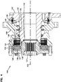
FIG. 6 , a cross-sectional view of the combined hydraulicmotor brake assembly 100 is shown. As discussed above, the combined hydraulic motor andbrake assembly 100 includes astationary housing 102 and a drivenhub 108. A sealing arrangement 109 (e.g., duo cone seals, X-ring seals, O-ring seals, etc.) is disposed betweenstationary housing 102 and the drivenhub 108 at various intervals.Stationary housing 102 defines ashaft passage 118. One ormore bearings 120 may be positioned between the drivenhub 108 and thestationary housing 102 to allow the drivenhub 108 to rotate relative to thestationary housing 102 about an axis ofrotation 103 that extends through theshaft passage 118. The axis ofrotation 103 is defined by thebearings 120. Any suitable bearing may be utilized. In some embodiments, thebearing 120 is a thrust bearing. The combined hydraulic motor andbrake assembly 100 further includes amain drive shaft 122 that extends through theshaft passage 118 of thestationary housing 102. - The combined hydraulic motor and
brake assembly 100 includes acoupler 124 for coupling themain drive shaft 122 to the drivenhub 108. Thecoupler 124 and the drivenhub 108 rotate as a unit about the axis ofrotation 103 when driven by thedrive shaft 122. Thecoupler 124 is coupled to the drivenhub 108 by a plurality of fasteners 131 (e.g., bolts, cams, etc.) that are circumferentially spaced around the axis ofrotation 103 along a perimeter of thecoupler 124. Themain drive shaft 122 is coupled to thecoupler 124 by a splined mechanical interface (e.g., a crown spline interface). Specifically, an end ofdrive shaft 122 includessplines 126 that engage withsplines 127 ofcoupler 124. Torque may be transferred frommain drive shaft 122 tocoupler 124 and the drivenhub 108 asmain drive shaft 122 is driven (e.g., by a hydraulic motor). An end plug 125 (seeFIG. 6 ) mounts to the coupler 24 and encloses the end of theshaft passage 118. Theend plug 125 can be threaded in thecoupler 124 and can oppose an end of thedrive shaft 122 in theshaft passage 118. -
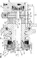
FIG. 6 shows a motor portion (e.g., hydraulic motor 142) and a brake portion (e.g., brake assembly 144) of the hydraulic motor and brake ofFIG. 1 . Thehydraulic motor 142 is configured to rotate themain drive shaft 122 relative to thestationary housing 102. In the depicted embodiment, the motor is rear-piloted, and includes amotor housing assembly 145 back-mounted to thestationary housing 102 viafasteners 147. In this way, thestationary housing 102 is fixed or stationary relative to themotor housing assembly 145. Other types of motor piloting and motor mounting configurations can be used as well. - The
hydraulic motor 142 includes anend cap 146 which may define one or more fluid inlet and outlet ports, as will be discussed further with reference toFIGS. 7-9 . In preferred embodiments, themotor 142 is a gerotor-type hydraulic motor. Disposed adjacent theend cap 146 is aport plate 148, and adjacent thereto (moving "forwardly", or to the left inFIG. 6 ) is a fluid displacement mechanism which, in the subject embodiment, comprises a gerotor assembly, generally designated 150. As is well known in the art, thegerotor assembly 150 may include a stator (e.g., an outer gear 152), which may be an internally-toothed ring member, and disposed therein, a rotor (e.g., an inner gear 154), which may be an externally-toothed star member, which undergoes orbital and rotational movement in response to pressurized fluid being communicated from an inlet port to one or more motor chambers. In such embodiments, themain drive shaft 122 is coupled to the inner gear 154 (e.g., by a splined connection). Rotation of theinner gear 154 within theouter gear 152 drives rotation of theshaft 122 about its central axis and also cause theshaft 122 to orbit about thecentral axis 103. It will be appreciated that the term "rotation" includes pure rotation as well as eccentric or wobbling type rotation. Theinner gear 154 is also coupled to a secondary shaft 156 (e.g. a valve drive shaft). The rotational movement of theinner gear 154 is transmitted by means of thesecondary shaft 156 to arotatable disk member 158. As is also well known to those skilled in the art, the function of therotatable disk member 158 is to control the communication of pressurized fluid from an inlet port to the gerotor gear set 150, and to control the communication of low pressure, exhaust fluid from the gerotor gear set 150 to an outlet port. Gerotor-type hydraulic motors can also include rollers in place of internal gear teeth that prevent direct contact between the rotor and the stator. Thus, Geroler® type hydraulic geroler motors sold by Eaton Corporation are considered gerotor-type hydraulic motors for the purposes of this disclosure. While gerotor-type hydraulic motors are preferred, other types of hydraulic motors can be used as well. - Referring to
FIGS. 3 and6 , theinner gear 154 of themotor 142 is in splined engagement with themain drive shaft 122. For example, themain drive shaft 122 has a rearward set of crownedsplines 160 in splined engagement withinternal splines 153 in theinner gear 154. Themain drive shaft 122 also includes a forward set of crowned splines (e.g., splines 126 ofFIG. 4 ) in splined engagement withinternal splines 127 ofcoupler 124. The forward splines 126 of themain drive shaft 122 mate with the coupler splines 127 to affect torque transfer between themain drive shaft 122 and thecoupler 124. One or more of the spline assemblies may be chamfered or beveled to aid in dynamic spline engagement. - The
brake portion 144 of the combined hydraulic motor andbrake assembly 100 includes abrake piston 128. Thepiston 128 may be a lock piston as is known in the art. Thepiston 128 frictionally engages with and be carried with thecoupler 124 and the drivenhub 108, thus rotating when thecoupler 124 and the drivenhub 108 are rotated about the axis ofrotation 103 by themain drive shaft 122. Thepiston 128 includes a plurality of sealing arrangements to prevent fluid leakage. Sealing arrangements are disposed between thepiston 128 and one or more other components ofassembly 100. A first sealing arrangement is located at an inside surface of the piston (e.g., to seal a piston inner diameter). An innerradial piston seal 130 is positioned between thepiston 128 and thecoupler 124 for frictionally engaging thepiston 128 and thecoupler 124. A second sealing arrangement is located at an outside surface of thepiston 128 from the first sealing arrangement (e.g., to seal a piston outer diameter). An outerradial piston seal 132 positioned between thepiston 128 and the drivenhub 108 for frictionally engaging thepiston 128 and the drivenhub 108. Innerradial piston seal 130 and outerradial piston seal 132 may comprise any suitable sealing means for sealingpiston 128. For example, each sealing arrangement may include one or more O-rings, X-rings, duo cone rings or other appropriate sealing structures. Seals may be constructed to be static or dynamic seals. However, regardless of seal-type utilized, innerradial piston seal 130 and outerradial piston seal 132 effectively become static seals whenpiston 128 rotates with thecoupler 124 and the drivenhub 108. Thus, piston seal life may improve and design flexibility may increase, as both piston seals are effectively static when the drivenhub 108 rotates. - The
brake portion 144 of the combined hydraulic motor andbrake assembly 100 also includes a brake disc assembly, orbrake pack 134.FIG. 5 is an exploded isometric view of brake pack components according to embodiments of the disclosure. When the brake pack is compressed, relative rotation is not allowed between the drivenhub 108 andstationary housing 102.Brake pack 134 includesfirst brake pads 135 mounted to thestationary housing 102 and second brake pads 136 carried by the drivenhub 108 such that the second brake pads 136 rotate relative to thefirst brake pads 135 when the drivenhub 108 rotates relative to thestationary housing 102. The first andsecond brake pads 135, 136 are interleaved relative to one another. A plurality ofserrations 143 may be disposed on at least a portion of the interior diameter of thefirst brake pads 135. Theserrations 143 engage with corresponding serrations 137 on thestationary housing 102 to limit relative rotation between thefirst brake pads 135 and thestationary housing 102. A plurality of tabs 139 may be disposed on outer diameters of the second brake pads 136. The tabs 139 fit withincorresponding tab slots 141 defined by the drivenhub 108 to limit relative rotation between the drivenhub 108 and the second brake pads 136. - Referring back to
FIG. 4 , thebrake assembly 144 of the combined hydraulic motor andbrake assembly 100 includes aspring assembly 138 for actuating thebrake pack 134. In some embodiments,spring assembly 138 may include a series of concentric springs. Concentric springs may be a plurality of conical disc shaped springs or washers located adjacent to one another. A first set of conical washers may be oriented in a first direction opposite to a second direction associated with a second set of conical washers. In one embodiment,spring assembly 138 comprises one or more Belleville washers or springs arranged in the described configuration. - The
spring assembly 138 may be located between thepiston 128 and thecoupler 124. An area between thepiston 128 and thecoupler 124 may be defined as a spring chamber. Thespring assembly 138 is compressed between thecoupler 124 and thepiston 128 such that the spring assembly is preloaded with a spring force, To engage the brake, thespring assembly 138 is configured to normally urge thepiston 128 against thebrake pack 134.Piston 128 may normally be biased to the right by the force ofspring assembly 138 thereby compressingbrake pack 134. According to the embodiments described herein,spring assembly 138 actuates thebrake pack 134 by applying a braking force through thepiston 128 to thebrake pack 134 to compress the first andsecond brake pads 135, 136 together such that relative rotation between the drivenhub 108 andstationary housing 102 is resisted by friction between the first andsecond brake pads 135, 136. When thebrake pack 134 is compressed, relative rotation between drivenhub 108 andstationary housing 102 is resisted or prevented. To release the brake, a brake release mechanism is configured to urge thepiston 128 away from thebrake pack 134 to decrease the braking force. The brake release mechanism may comprise hydraulic fluid, pneumatic pressure or mechanical means that applies an opposite force against thepiston 128, to counteract the spring force of thespring assembly 138. The combined hydraulic motor andbrake assembly 100 may include abrake chamber 140 formed on the brake pad side of the piston 128 (i.e., the side opposite the spring assembly 138). To release the brake,brake chamber 140 may be pressurized.Brake chamber 140 may be sealed with one or more O-rings, X-rings or any other suitable sealing means. When the brake is released, rotation of the drivenhub 108,coupler 124,piston 128, second brake pads 136 andspring assembly 138 relative to thestationary housing 102 is permitted. In certain embodiments, thechamber 140 is pressurized by placing thechamber 140 in fluid communication with a pilot/charge pressure of the hydraulic circuit powering thehydraulic motor 142. - The
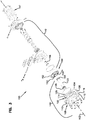
motor 142 of the combined hydraulic motor andbrake assembly 100 may include a plurality of fluid ports, as shown inFIGS. 7-9 . As is known in the art, themotor 142 may include one or more ports providing fluid inlets and/or outlets in communication with one or more portions of the interior of themotor 142. As is illustrated inFIG. 7 ports may include first and secondmain ports Ports Valve 143 controls fluid communication between apump 178 and theports ports tank 180. Thepump 178 can be driven by avehicle engine 176 or other engine. Thevalve 143 also has a neutral position that connects thepump 178 to thereservoir 180. In other embodiments, the valve can be configured to connect theports valve 143 allows themotor 142 to be bi-directional. Themotor 142 may further include acase drain port 166. Leaked or drained oil in the case is typically ported to thehydraulic reservoir tank 180, which is at low pressure, by use of a drain system employing internal valves within the case (e.g., shuttle valves, check valves, etc.). Themotor 142 may include abrake release port 168. As is now well known to those skilled in the art, the hydraulic pressure to disengage the brake may be internal case pressure, or an external "pilot" pressure from a system charge pump 174, or any other suitable source of pressure. Charge pump 174 may be driven by thevehicle engine 176 and hydraulically coupled to themain pump 178. Acontroller 184 may at least partly control acontrol valve 182 fluidly connected to thebrake release port 168 and/or, a high pressure side of the charge pump 174. Thecontrol valve 182 may be operable to selectively deliver pressurized fluid (e.g., charge or pilot pressure generated by the charge pump 174) to thebrake release port 168. Themotor 142 may also include ashift port 170. It is further contemplated that a combined hydraulic motor and brake assembly according to embodiments of the disclosure may include more or less ports than are shown inFIG. 7 . - Referring to
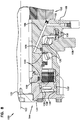
FIG. 8 ,passage 186 defined by thestationary housing 102 provides fluid communication between thecharge port 168 and thebrake chamber 140. When thevalve 182 opens fluid communication between the charge pump 174 and thecharge port 168, thepassage 186 provides fluid communication between thecharge port 168 and thebrake chamber 140. In this way, charge pressure is provided to thebrake chamber 140 causing thepiston 128 to move away from thebrake pack 134 against the bias of thespring 138 to release the brake. - Referring to
FIG. 9 ,passage 188 defined at least in part by thestationary housing 102 provides fluid communication between thecase drain port 166 and an interior of the assembly forming a case drain region. In operation of themotor 142, case drain fluid (e.g., hydraulic oil) is shuttled from themotor 142 throughsplines 160 into theshaft opening 118. The case drain fluid then flows axially along theshaft opening 118, throughsplines 126 to acavity 200 at the front end of theshaft 122. From thecavity 200, the case drain fluid flows throughpassage 201 defined by thecoupler 124 to acavity 203 at the rear of thecoupler 124. From thecavity 203, the case drain fluid flows through thepassage 188 to thecase drain port 166. From thecase drain port 166, case drain flow proceeds toreservoir 180. - The described embodiments may be implemented with any hydraulic device that includes a hydraulic motor and brake assembly. The described embodiments may also provide a smaller form-factor hydraulic motor and brake assembly, further decreasing costs and increasing design flexibility.
- The above specification, examples and data provide a complete description of the manufacture and use of the composition of the invention. Since many embodiments of the invention can be made without departing from the scope of the invention, the invention resides in the claims hereinafter appended.
Claims (10)
- A combined hydraulic motor (142) and brake (144) comprising:a stationary housing (102) defining a shaft passage (118);a driven hub (108);a bearing (120) positioned between the driven hub (108) and the stationary housing (102) for allowing the driven hub (108) to rotate relative to the stationary housing (102) about an axis of rotation (103) that extends through the shaft passage (118);a drive shaft (122) that extends through the shaft passage (118) of the stationary housing (102);hydraulic motor (142) for rotating the drive shaft (122) relative to the stationary housing (102);a coupler (124) for coupling the drive shaft (122) to the driven hub (108) such that the coupler (124) and the driven hub (108) rotate as a unit about the axis of rotation (103) when the drive shaft (122) is rotated by the hydraulic motor (142);a brake (144) including a brake pack (134) having first brake pads (135) mounted to the stationary housing (102) and second brake pads (136) carried by the driven hub (108) such that the second brake pads (136) rotate relative to the first brake pads (135) when the driven hub (108) rotates relative to the stationary housing (102), the first and second brake pads (135, 136) being interleaved relative to one another;a brake piston and a spring (138) for actuating the brake (144) by applying a braking force through the brake piston (128) to the brake pack (134) to compress the first and second brake pads (135, 136) together such that relative rotation between the driven hub (108) and the stationary housing (102) is resisted by friction between the first and second brake pads (135, 136), and wherein the brake (144) is released by applying hydraulic pressure to the brake piston (128) to generate a brake release force that opposes the braking force;
characterized by the brake piston (128) being carried with the coupler (124) and the driven hub (108) when the coupler (124) and driven hub (108) are rotated about the axis of rotation (103);an outer radial piston seal (132) positioned between the brake piston (128) and the driven hub (108);an inner radial piston seal (130) positioned between the brake piston (128) and the coupler (124), the outer radial piston seal (132) and the inner radial piston seal (130) both remaining substantially static as the brake piston (128) rotates with the driven hub (108) and the coupler (124). - The combined hydraulic motor (142) and brake (144) of claim 1, wherein the hydraulic motor (142) is a gerotor-type hydraulic motor including a rotor (154) and a stator (152), wherein the drive shaft (122) is coupled to the rotor (154).
- The combined hydraulic motor (142) and brake (144) of claim 1, wherein the drive shaft (122) is coupled to the coupler (124) by a splined mechanical interface.
- The combined hydraulic motor (142) and brake (144) of claim 1, wherein the coupler (124) is coupled to the driven hub (108) by a plurality of fasteners (131) that are circumferentially spaced around the axis of rotation (103) along a perimeter of the coupler (124).
- The combined hydraulic motor (142) and brake (144) of claim 1, wherein the stationary housing (102) includes a mounting flange (104) that projects radially outwardly from a main body (105) of the stationary housing (102), the mounting flange (104) defining a plurality of first fastener openings (106) for receiving first fasteners used to secure the stationary housing (102) to a non-driven/stationary element.
- The combined hydraulic motor (142) and brake (144) of claim 5, wherein the driven hub (108) includes a plurality of second fastener openings (110) for receiving second fasteners (114) used to secure the driven hub (108) to a driven element.
- The combined hydraulic motor (142) and brake (144) of claim 5, wherein the non-driven/stationary element includes a portion of a vehicle frame, and wherein the driven element is selected from the group consisting of a wheel and a gear.
- The combined hydraulic motor (142) and brake (144) of claim 5, wherein the mounting flange (104) is generally semi-circular in shape.
- The combined hydraulic motor (142) and brake (144) of claim 6, wherein the driven hub (108) includes a main body (112) and a plurality of tabs (114) that project radially outwardly from the main body (112), the tabs (114) being circumferentially spaced around the axis of rotation (103) along a perimeter of the main body (112) of the driven hub (108), the second fastener openings (110) being defined through the tabs (114).
- The combined hydraulic motor (142) and brake (144) of claim 9, wherein the tabs (114) are separated by pockets (116), and wherein at least some of the pockets (116) align with the first fastener openings (106) to facilitate accessing the first fastener openings (106).
Applications Claiming Priority (2)
| Application Number | Priority Date | Filing Date | Title |
|---|---|---|---|
| US201261672979P | 2012-07-18 | 2012-07-18 | |
| PCT/US2013/050807 WO2014014984A2 (en) | 2012-07-18 | 2013-07-17 | Combined motor and brake with rotating brake-release piston |
Publications (2)
| Publication Number | Publication Date |
|---|---|
| EP2895739A2 EP2895739A2 (en) | 2015-07-22 |
| EP2895739B1 true EP2895739B1 (en) | 2021-05-12 |
Family
ID=48877573
Family Applications (1)
| Application Number | Title | Priority Date | Filing Date |
|---|---|---|---|
| EP13742359.6A Active EP2895739B1 (en) | 2012-07-18 | 2013-07-17 | Combined motor and brake with rotating brake-release piston |
Country Status (6)
| Country | Link |
|---|---|
| US (1) | US9175563B2 (en) |
| EP (1) | EP2895739B1 (en) |
| JP (1) | JP6214652B2 (en) |
| KR (1) | KR20150038041A (en) |
| CN (1) | CN104583585B (en) |
| WO (1) | WO2014014984A2 (en) |
Families Citing this family (12)
| Publication number | Priority date | Publication date | Assignee | Title |
|---|---|---|---|---|
| EP3221560B1 (en) | 2014-11-17 | 2020-01-01 | Eaton Corporation | Rotary fluid pressure device with drive-in-drive valve arrangement |
| FR3030382B1 (en) * | 2014-12-23 | 2017-01-13 | Poclain Hydraulics Ind | HYDRAULIC TORQUE MOTOR |
| US10781816B2 (en) | 2017-04-13 | 2020-09-22 | Eaton Intelligent Power Limited | Hydraulic motor brake |
| US10465758B2 (en) | 2017-07-26 | 2019-11-05 | Ingersoll-Rand Company | Rotatable shaft with fluid actuated lock piston |
| CN107882900A (en) * | 2017-12-25 | 2018-04-06 | 徐工集团工程机械有限公司 | Brake and engineering truck |
| WO2019236295A1 (en) * | 2018-06-07 | 2019-12-12 | Parker-Hannifin Corporation | Hydraulic motor subassembly kit with carrier |
| DE102018215935A1 (en) * | 2018-09-19 | 2020-03-19 | ZF Drivetech (Suzhou) Co.Ltd. | Electrically driven axle |
| CN109606335B (en) * | 2018-12-27 | 2021-03-30 | 六安江淮电机有限公司 | Efficient auxiliary braking method for brake motor |
| CN111980913A (en) * | 2019-05-23 | 2020-11-24 | 镇江大力液压马达股份有限公司 | Hydraulic brake motor device |
| CN110125851A (en) * | 2019-06-24 | 2019-08-16 | 杭州力龙液压有限公司 | The assembly tooling of hydraulic motor brake cylinder |
| CN114341049B (en) * | 2019-07-26 | 2023-10-20 | 奥克斯工业股份有限公司 | Electric rotary actuator for aerial work platform |
| EP3792517A1 (en) | 2019-09-13 | 2021-03-17 | Dana Italia S.r.L. | Wet brake system and method of operating a wet brake system |
Family Cites Families (29)
| Publication number | Priority date | Publication date | Assignee | Title |
|---|---|---|---|---|
| US3870377A (en) | 1972-07-15 | 1975-03-11 | Itt | Brake pressure modulator |
| US3863038A (en) * | 1973-06-26 | 1975-01-28 | Lambert & Brake Corp | Disc brake |
| US4187931A (en) | 1977-07-18 | 1980-02-12 | Caterpillar Tractor Co. | Brake housing and actuating mechanism |
| US4736821A (en) * | 1981-10-02 | 1988-04-12 | Rockwell International Corporation | Fluid cooled friction brake |
| DE3211366C2 (en) | 1982-03-27 | 1985-05-30 | Zahnradfabrik Friedrichshafen Ag, 7990 Friedrichshafen | Spring-loaded brake with pressurized release device |
| US4645039A (en) | 1985-06-20 | 1987-02-24 | Wiseda Ltd. | Parking brake for off-highway vehicles |
| US4981423A (en) * | 1989-10-03 | 1991-01-01 | Trw Inc. | Hydraulic motor with wobble-stick and brake assembly |
| FI104014B1 (en) * | 1994-05-18 | 1999-10-29 | Valmet Voimansiirto Oy | Radial piston hydraulic motor and method for adjusting radial hydraulic motor |
| JPH1073001A (en) * | 1996-07-05 | 1998-03-17 | Linde Ag | Swash plate axial piston motor |
| US5967750A (en) * | 1997-10-10 | 1999-10-19 | Elliott; Morris C. | Variable pitch marine propeller |
| US6253882B1 (en) * | 1999-02-22 | 2001-07-03 | White Hydraulics, Inc. | Motor with symmetric braking system |
| US6336729B1 (en) * | 1999-05-20 | 2002-01-08 | Richard Pavelle | Emergency light device |
| US6132194A (en) | 1999-06-03 | 2000-10-17 | Eaton Corporation | Low cost compact design integral brake |
| FR2796992B1 (en) | 1999-07-27 | 2001-10-19 | Poclain Hydraulics Ind | HYDRAULIC MOTOR WITH RADIAL PISTONS AND SINGLE CLUTCH SELECTOR |
| US6321882B1 (en) | 1999-08-25 | 2001-11-27 | Eaton Corporation | External manual brake release |
| DE10006460B4 (en) * | 2000-02-14 | 2010-06-24 | Linde Material Handling Gmbh | hub drive |
| DE10055261A1 (en) * | 2000-11-08 | 2002-05-23 | Linde Ag | Hydrostatic axial piston machine in inclined disc construction method |
| DE10147852A1 (en) | 2001-09-27 | 2003-04-10 | Zahnradfabrik Friedrichshafen | driving device |
| JP2003336669A (en) * | 2002-05-20 | 2003-11-28 | Komatsu Ltd | Brake device for hydraulic motor |
| US20040060779A1 (en) | 2002-10-01 | 2004-04-01 | Charles Kreger | Distance compensating shim for clutch/brake and method of determining same |
| US6772863B2 (en) | 2002-10-21 | 2004-08-10 | Sauer-Danfoss (Nordborg) A/S | Brake appliance for gerotor motors |
| US6743002B1 (en) | 2003-02-03 | 2004-06-01 | Eaton Corporation | Rotary fluid pressure device and improved integral brake assembly |
| CN2707583Y (en) * | 2004-05-12 | 2005-07-06 | 长沙航空工业中南传动机械厂 | Enclosed type braking and driving axle |
| US7287969B2 (en) * | 2005-01-18 | 2007-10-30 | Eaton Corporation | Rotary fluid pressure device and improved brake assembly for use therewith |
| WO2007083232A2 (en) | 2006-01-20 | 2007-07-26 | Eaton Corporation | Rotary fluid pressure device and improved parking lock assembly therefor |
| US7695258B2 (en) | 2006-05-08 | 2010-04-13 | White Drive Products, Inc. | Gerotor motor and brake assembly |
| US7431124B2 (en) | 2006-10-06 | 2008-10-07 | White Drive Products, Inc. | Hydraulic transmission assembly |
| FR2926854B1 (en) | 2008-01-29 | 2010-03-26 | Poclain Hydraulics Ind | HYDRAULIC ENGINE DEVICE FOR ASSISTING THE MECHANICAL TRANSMISSION OF A VEHICLE. |
| CN201705841U (en) * | 2010-03-19 | 2011-01-12 | 山东蓬翔汽车有限公司 | Self-regulating wet type multi-disc brake |
-
2013
- 2013-07-17 JP JP2015523201A patent/JP6214652B2/en active Active
- 2013-07-17 CN CN201380038257.XA patent/CN104583585B/en active Active
- 2013-07-17 US US13/944,405 patent/US9175563B2/en active Active
- 2013-07-17 EP EP13742359.6A patent/EP2895739B1/en active Active
- 2013-07-17 WO PCT/US2013/050807 patent/WO2014014984A2/en active Application Filing
- 2013-07-17 KR KR20157003563A patent/KR20150038041A/en not_active Application Discontinuation
Non-Patent Citations (1)
| Title |
|---|
| None * |
Also Published As
| Publication number | Publication date |
|---|---|
| JP6214652B2 (en) | 2017-10-18 |
| EP2895739A2 (en) | 2015-07-22 |
| US20140023543A1 (en) | 2014-01-23 |
| JP2015524529A (en) | 2015-08-24 |
| WO2014014984A2 (en) | 2014-01-23 |
| WO2014014984A3 (en) | 2014-07-31 |
| CN104583585B (en) | 2016-12-28 |
| US9175563B2 (en) | 2015-11-03 |
| KR20150038041A (en) | 2015-04-08 |
| CN104583585A (en) | 2015-04-29 |
Similar Documents
| Publication | Publication Date | Title |
|---|---|---|
| EP2895739B1 (en) | Combined motor and brake with rotating brake-release piston | |
| EP2875237B1 (en) | Freewheel hydraulic motor | |
| US8662277B2 (en) | Planetary gearbox with integral service brake | |
| EP0421616B1 (en) | Hydraulic device | |
| EP2018369B1 (en) | Gerotor motor and brake assembly | |
| US20150233467A1 (en) | Planetary gearbox with integral service brake | |
| US20080173515A1 (en) | Disk spring hydraulic release brake | |
| US10214101B2 (en) | Work vehicle drive assembly | |
| EP2594825A1 (en) | Power transmission device | |
| US8631913B2 (en) | Brake assembly for final drive | |
| JPS58118423A (en) | Assembled body of driving accelerator | |
| EP1974145B1 (en) | Rotary fluid pressure device and improved parking lock assembly therefor | |
| EP0040049B1 (en) | Brake system | |
| KR102065906B1 (en) | Internal gear pump | |
| RU2114011C1 (en) | Vehicle hub motor | |
| WO2002059482A1 (en) | An integral unit of a hydraulic brake/gerotor hydraulic motor a nd a control valve block | |
| US20170363192A1 (en) | Hydraulic device with sleeve insert | |
| JP2620314B2 (en) | Driving force transmission device | |
| JPH05133427A (en) | Driving force transmission device for four-wheel drive vehicle | |
| JPH05139179A (en) | Driving force transmitting device for four-wheel drive vehicle | |
| JPH05139180A (en) | Driving force transmitting device for four-wheel drive vehicle |
Legal Events
| Date | Code | Title | Description |
|---|---|---|---|
| PUAI | Public reference made under article 153(3) epc to a published international application that has entered the european phase |
Free format text: ORIGINAL CODE: 0009012 |
|
| 17P | Request for examination filed |
Effective date: 20150216 |
|
| AK | Designated contracting states |
Kind code of ref document: A2 Designated state(s): AL AT BE BG CH CY CZ DE DK EE ES FI FR GB GR HR HU IE IS IT LI LT LU LV MC MK MT NL NO PL PT RO RS SE SI SK SM TR |
|
| AX | Request for extension of the european patent |
Extension state: BA ME |
|
| DAX | Request for extension of the european patent (deleted) | ||
| STAA | Information on the status of an ep patent application or granted ep patent |
Free format text: STATUS: EXAMINATION IS IN PROGRESS |
|
| 17Q | First examination report despatched |
Effective date: 20161216 |
|
| RAP1 | Party data changed (applicant data changed or rights of an application transferred) |
Owner name: EATON INTELLIGENT POWER LIMITED |
|
| GRAP | Despatch of communication of intention to grant a patent |
Free format text: ORIGINAL CODE: EPIDOSNIGR1 |
|
| STAA | Information on the status of an ep patent application or granted ep patent |
Free format text: STATUS: GRANT OF PATENT IS INTENDED |
|
| INTG | Intention to grant announced |
Effective date: 20201207 |
|
| GRAS | Grant fee paid |
Free format text: ORIGINAL CODE: EPIDOSNIGR3 |
|
| GRAA | (expected) grant |
Free format text: ORIGINAL CODE: 0009210 |
|
| STAA | Information on the status of an ep patent application or granted ep patent |
Free format text: STATUS: THE PATENT HAS BEEN GRANTED |
|
| AK | Designated contracting states |
Kind code of ref document: B1 Designated state(s): AL AT BE BG CH CY CZ DE DK EE ES FI FR GB GR HR HU IE IS IT LI LT LU LV MC MK MT NL NO PL PT RO RS SE SI SK SM TR |
|
| REG | Reference to a national code |
Ref country code: GB Ref legal event code: FG4D |
|
| REG | Reference to a national code |
Ref country code: CH Ref legal event code: EP |
|
| REG | Reference to a national code |
Ref country code: DE Ref legal event code: R096 Ref document number: 602013077457 Country of ref document: DE |
|
| REG | Reference to a national code |
Ref country code: IE Ref legal event code: FG4D |
|
| REG | Reference to a national code |
Ref country code: AT Ref legal event code: REF Ref document number: 1392340 Country of ref document: AT Kind code of ref document: T Effective date: 20210615 |
|
| REG | Reference to a national code |
Ref country code: LT Ref legal event code: MG9D |
|
| REG | Reference to a national code |
Ref country code: AT Ref legal event code: MK05 Ref document number: 1392340 Country of ref document: AT Kind code of ref document: T Effective date: 20210512 |
|
| REG | Reference to a national code |
Ref country code: NL Ref legal event code: MP Effective date: 20210512 |
|
| PG25 | Lapsed in a contracting state [announced via postgrant information from national office to epo] |
Ref country code: AT Free format text: LAPSE BECAUSE OF FAILURE TO SUBMIT A TRANSLATION OF THE DESCRIPTION OR TO PAY THE FEE WITHIN THE PRESCRIBED TIME-LIMIT Effective date: 20210512 Ref country code: BG Free format text: LAPSE BECAUSE OF FAILURE TO SUBMIT A TRANSLATION OF THE DESCRIPTION OR TO PAY THE FEE WITHIN THE PRESCRIBED TIME-LIMIT Effective date: 20210812 Ref country code: HR Free format text: LAPSE BECAUSE OF FAILURE TO SUBMIT A TRANSLATION OF THE DESCRIPTION OR TO PAY THE FEE WITHIN THE PRESCRIBED TIME-LIMIT Effective date: 20210512 Ref country code: FI Free format text: LAPSE BECAUSE OF FAILURE TO SUBMIT A TRANSLATION OF THE DESCRIPTION OR TO PAY THE FEE WITHIN THE PRESCRIBED TIME-LIMIT Effective date: 20210512 Ref country code: LT Free format text: LAPSE BECAUSE OF FAILURE TO SUBMIT A TRANSLATION OF THE DESCRIPTION OR TO PAY THE FEE WITHIN THE PRESCRIBED TIME-LIMIT Effective date: 20210512 |
|
| PG25 | Lapsed in a contracting state [announced via postgrant information from national office to epo] |
Ref country code: IS Free format text: LAPSE BECAUSE OF FAILURE TO SUBMIT A TRANSLATION OF THE DESCRIPTION OR TO PAY THE FEE WITHIN THE PRESCRIBED TIME-LIMIT Effective date: 20210912 Ref country code: LV Free format text: LAPSE BECAUSE OF FAILURE TO SUBMIT A TRANSLATION OF THE DESCRIPTION OR TO PAY THE FEE WITHIN THE PRESCRIBED TIME-LIMIT Effective date: 20210512 Ref country code: GR Free format text: LAPSE BECAUSE OF FAILURE TO SUBMIT A TRANSLATION OF THE DESCRIPTION OR TO PAY THE FEE WITHIN THE PRESCRIBED TIME-LIMIT Effective date: 20210813 Ref country code: ES Free format text: LAPSE BECAUSE OF FAILURE TO SUBMIT A TRANSLATION OF THE DESCRIPTION OR TO PAY THE FEE WITHIN THE PRESCRIBED TIME-LIMIT Effective date: 20210512 Ref country code: NO Free format text: LAPSE BECAUSE OF FAILURE TO SUBMIT A TRANSLATION OF THE DESCRIPTION OR TO PAY THE FEE WITHIN THE PRESCRIBED TIME-LIMIT Effective date: 20210812 Ref country code: PT Free format text: LAPSE BECAUSE OF FAILURE TO SUBMIT A TRANSLATION OF THE DESCRIPTION OR TO PAY THE FEE WITHIN THE PRESCRIBED TIME-LIMIT Effective date: 20210913 Ref country code: PL Free format text: LAPSE BECAUSE OF FAILURE TO SUBMIT A TRANSLATION OF THE DESCRIPTION OR TO PAY THE FEE WITHIN THE PRESCRIBED TIME-LIMIT Effective date: 20210512 Ref country code: RS Free format text: LAPSE BECAUSE OF FAILURE TO SUBMIT A TRANSLATION OF THE DESCRIPTION OR TO PAY THE FEE WITHIN THE PRESCRIBED TIME-LIMIT Effective date: 20210512 Ref country code: SE Free format text: LAPSE BECAUSE OF FAILURE TO SUBMIT A TRANSLATION OF THE DESCRIPTION OR TO PAY THE FEE WITHIN THE PRESCRIBED TIME-LIMIT Effective date: 20210512 |
|
| PG25 | Lapsed in a contracting state [announced via postgrant information from national office to epo] |
Ref country code: NL Free format text: LAPSE BECAUSE OF FAILURE TO SUBMIT A TRANSLATION OF THE DESCRIPTION OR TO PAY THE FEE WITHIN THE PRESCRIBED TIME-LIMIT Effective date: 20210512 |
|
| REG | Reference to a national code |
Ref country code: DE Ref legal event code: R081 Ref document number: 602013077457 Country of ref document: DE Owner name: DANFOSS POWER SOLUTIONS II TECHNOLOGY A/S, DK Free format text: FORMER OWNER: EATON INTELLIGENT POWER LIMITED, DUBLIN, IE |
|
| PG25 | Lapsed in a contracting state [announced via postgrant information from national office to epo] |
Ref country code: RO Free format text: LAPSE BECAUSE OF FAILURE TO SUBMIT A TRANSLATION OF THE DESCRIPTION OR TO PAY THE FEE WITHIN THE PRESCRIBED TIME-LIMIT Effective date: 20210512 Ref country code: SM Free format text: LAPSE BECAUSE OF FAILURE TO SUBMIT A TRANSLATION OF THE DESCRIPTION OR TO PAY THE FEE WITHIN THE PRESCRIBED TIME-LIMIT Effective date: 20210512 Ref country code: SK Free format text: LAPSE BECAUSE OF FAILURE TO SUBMIT A TRANSLATION OF THE DESCRIPTION OR TO PAY THE FEE WITHIN THE PRESCRIBED TIME-LIMIT Effective date: 20210512 Ref country code: CZ Free format text: LAPSE BECAUSE OF FAILURE TO SUBMIT A TRANSLATION OF THE DESCRIPTION OR TO PAY THE FEE WITHIN THE PRESCRIBED TIME-LIMIT Effective date: 20210512 Ref country code: DK Free format text: LAPSE BECAUSE OF FAILURE TO SUBMIT A TRANSLATION OF THE DESCRIPTION OR TO PAY THE FEE WITHIN THE PRESCRIBED TIME-LIMIT Effective date: 20210512 Ref country code: EE Free format text: LAPSE BECAUSE OF FAILURE TO SUBMIT A TRANSLATION OF THE DESCRIPTION OR TO PAY THE FEE WITHIN THE PRESCRIBED TIME-LIMIT Effective date: 20210512 |
|
| REG | Reference to a national code |
Ref country code: DE Ref legal event code: R097 Ref document number: 602013077457 Country of ref document: DE |
|
| REG | Reference to a national code |
Ref country code: CH Ref legal event code: PL |
|
| PLBE | No opposition filed within time limit |
Free format text: ORIGINAL CODE: 0009261 |
|
| STAA | Information on the status of an ep patent application or granted ep patent |
Free format text: STATUS: NO OPPOSITION FILED WITHIN TIME LIMIT |
|
| PG25 | Lapsed in a contracting state [announced via postgrant information from national office to epo] |
Ref country code: MC Free format text: LAPSE BECAUSE OF FAILURE TO SUBMIT A TRANSLATION OF THE DESCRIPTION OR TO PAY THE FEE WITHIN THE PRESCRIBED TIME-LIMIT Effective date: 20210512 |
|
| REG | Reference to a national code |
Ref country code: BE Ref legal event code: MM Effective date: 20210731 |
|
| 26N | No opposition filed |
Effective date: 20220215 |
|
| GBPC | Gb: european patent ceased through non-payment of renewal fee |
Effective date: 20210812 |
|
| PG25 | Lapsed in a contracting state [announced via postgrant information from national office to epo] |
Ref country code: LI Free format text: LAPSE BECAUSE OF NON-PAYMENT OF DUE FEES Effective date: 20210731 Ref country code: CH Free format text: LAPSE BECAUSE OF NON-PAYMENT OF DUE FEES Effective date: 20210731 |
|
| PG25 | Lapsed in a contracting state [announced via postgrant information from national office to epo] |
Ref country code: IS Free format text: LAPSE BECAUSE OF FAILURE TO SUBMIT A TRANSLATION OF THE DESCRIPTION OR TO PAY THE FEE WITHIN THE PRESCRIBED TIME-LIMIT Effective date: 20210912 Ref country code: LU Free format text: LAPSE BECAUSE OF NON-PAYMENT OF DUE FEES Effective date: 20210717 Ref country code: AL Free format text: LAPSE BECAUSE OF FAILURE TO SUBMIT A TRANSLATION OF THE DESCRIPTION OR TO PAY THE FEE WITHIN THE PRESCRIBED TIME-LIMIT Effective date: 20210512 |
|
| PG25 | Lapsed in a contracting state [announced via postgrant information from national office to epo] |
Ref country code: IT Free format text: LAPSE BECAUSE OF FAILURE TO SUBMIT A TRANSLATION OF THE DESCRIPTION OR TO PAY THE FEE WITHIN THE PRESCRIBED TIME-LIMIT Effective date: 20210512 Ref country code: IE Free format text: LAPSE BECAUSE OF NON-PAYMENT OF DUE FEES Effective date: 20210717 Ref country code: GB Free format text: LAPSE BECAUSE OF NON-PAYMENT OF DUE FEES Effective date: 20210812 Ref country code: BE Free format text: LAPSE BECAUSE OF NON-PAYMENT OF DUE FEES Effective date: 20210731 |
|
| PG25 | Lapsed in a contracting state [announced via postgrant information from national office to epo] |
Ref country code: HU Free format text: LAPSE BECAUSE OF FAILURE TO SUBMIT A TRANSLATION OF THE DESCRIPTION OR TO PAY THE FEE WITHIN THE PRESCRIBED TIME-LIMIT; INVALID AB INITIO Effective date: 20130717 |
|
| PG25 | Lapsed in a contracting state [announced via postgrant information from national office to epo] |
Ref country code: CY Free format text: LAPSE BECAUSE OF FAILURE TO SUBMIT A TRANSLATION OF THE DESCRIPTION OR TO PAY THE FEE WITHIN THE PRESCRIBED TIME-LIMIT Effective date: 20210512 |
|
| P01 | Opt-out of the competence of the unified patent court (upc) registered |
Effective date: 20230617 |
|
| PGFP | Annual fee paid to national office [announced via postgrant information from national office to epo] |
Ref country code: FR Payment date: 20230622 Year of fee payment: 11 |
|
| PGFP | Annual fee paid to national office [announced via postgrant information from national office to epo] |
Ref country code: DE Payment date: 20230607 Year of fee payment: 11 |