EP2895643B1 - Externally-reinforced water electrolyser module - Google Patents
Externally-reinforced water electrolyser module Download PDFInfo
- Publication number
- EP2895643B1 EP2895643B1 EP13836294.2A EP13836294A EP2895643B1 EP 2895643 B1 EP2895643 B1 EP 2895643B1 EP 13836294 A EP13836294 A EP 13836294A EP 2895643 B1 EP2895643 B1 EP 2895643B1
- Authority
- EP
- European Patent Office
- Prior art keywords
- structural
- plates
- structural plates
- electrolyser
- plate
- Prior art date
- Legal status (The legal status is an assumption and is not a legal conclusion. Google has not performed a legal analysis and makes no representation as to the accuracy of the status listed.)
- Active
Links
- 0 CCNNNN=CNC*NCC***N* Chemical compound CCNNNN=CNC*NCC***N* 0.000 description 1
Images


Classifications
-
- C—CHEMISTRY; METALLURGY
- C25—ELECTROLYTIC OR ELECTROPHORETIC PROCESSES; APPARATUS THEREFOR
- C25B—ELECTROLYTIC OR ELECTROPHORETIC PROCESSES FOR THE PRODUCTION OF COMPOUNDS OR NON-METALS; APPARATUS THEREFOR
- C25B1/00—Electrolytic production of inorganic compounds or non-metals
- C25B1/01—Products
- C25B1/02—Hydrogen or oxygen
- C25B1/04—Hydrogen or oxygen by electrolysis of water
-
- C—CHEMISTRY; METALLURGY
- C25—ELECTROLYTIC OR ELECTROPHORETIC PROCESSES; APPARATUS THEREFOR
- C25B—ELECTROLYTIC OR ELECTROPHORETIC PROCESSES FOR THE PRODUCTION OF COMPOUNDS OR NON-METALS; APPARATUS THEREFOR
- C25B9/00—Cells or assemblies of cells; Constructional parts of cells; Assemblies of constructional parts, e.g. electrode-diaphragm assemblies; Process-related cell features
- C25B9/70—Assemblies comprising two or more cells
- C25B9/73—Assemblies comprising two or more cells of the filter-press type
- C25B9/77—Assemblies comprising two or more cells of the filter-press type having diaphragms
-
- Y—GENERAL TAGGING OF NEW TECHNOLOGICAL DEVELOPMENTS; GENERAL TAGGING OF CROSS-SECTIONAL TECHNOLOGIES SPANNING OVER SEVERAL SECTIONS OF THE IPC; TECHNICAL SUBJECTS COVERED BY FORMER USPC CROSS-REFERENCE ART COLLECTIONS [XRACs] AND DIGESTS
- Y02—TECHNOLOGIES OR APPLICATIONS FOR MITIGATION OR ADAPTATION AGAINST CLIMATE CHANGE
- Y02E—REDUCTION OF GREENHOUSE GAS [GHG] EMISSIONS, RELATED TO ENERGY GENERATION, TRANSMISSION OR DISTRIBUTION
- Y02E60/00—Enabling technologies; Technologies with a potential or indirect contribution to GHG emissions mitigation
- Y02E60/10—Energy storage using batteries
-
- Y—GENERAL TAGGING OF NEW TECHNOLOGICAL DEVELOPMENTS; GENERAL TAGGING OF CROSS-SECTIONAL TECHNOLOGIES SPANNING OVER SEVERAL SECTIONS OF THE IPC; TECHNICAL SUBJECTS COVERED BY FORMER USPC CROSS-REFERENCE ART COLLECTIONS [XRACs] AND DIGESTS
- Y02—TECHNOLOGIES OR APPLICATIONS FOR MITIGATION OR ADAPTATION AGAINST CLIMATE CHANGE
- Y02E—REDUCTION OF GREENHOUSE GAS [GHG] EMISSIONS, RELATED TO ENERGY GENERATION, TRANSMISSION OR DISTRIBUTION
- Y02E60/00—Enabling technologies; Technologies with a potential or indirect contribution to GHG emissions mitigation
- Y02E60/30—Hydrogen technology
- Y02E60/36—Hydrogen production from non-carbon containing sources, e.g. by water electrolysis
Definitions
- the present invention relates to the design of water electrolysers for the production of hydrogen and oxygen gases at elevated pressures, and more particularly, to alkaline and polymer electrolyte membrane (PEM) type electrolyser stacks and electrolyser modules with enhanced capability for operation at elevated pressures, and components therefor.
- PEM polymer electrolyte membrane
- Electrolysers use electricity to transform reactant chemicals to desired product chemicals through electrochemical reactions, i.e., reactions that occur at electrodes that are in contact with an electrolyte.
- Hydrogen is a product chemical of increasing demand for use in chemical processes, and also potentially for use in hydrogen vehicles and equipment powered by hydrogen fuel cell engines or hydrogen internal combustion engines (or hybrid hydrogen vehicles, also partially powered by batteries).
- Water electrolysers which produce hydrogen and oxygen from water and electricity, are the most common type of electrolyser used for production of gaseous hydrogen as the main product.
- the most common types of commercial water electrolysers are alkaline water electrolysers (AWE) and polymer electrolyte membrane (PEM) water electrolysers.
- half cell As used herein, the terms “half cell”, “half electrolysis cell” and equivalent variations thereof refer to a structure comprising one electrode and its corresponding half cell chamber that provides space for gas-liquid (or gas) flow out of the half cell.
- cathode half cell refers to a half cell containing a cathode
- anode half cell refers to a half cell containing an anode.
- the terms “cell”, “electrolysis cell” and equivalent variations thereof refer to a structure comprising a cathode half cell and an anode half cell.
- a cell also includes a separator membrane (referred to herein after as a “membrane”), typically located between, and in close proximity to, in contact with, or integral with, the cathodes and anodes.
- the functionality of the membrane is to maintain the hydrogen and oxygen gases produced separate and of high purity, while allowing for ionic conduction of electricity between the anode and cathode.
- a membrane therefore defines one side of each half cell.
- each half cell is defined by an electronically conducting solid plate, typically comprised of metal, carbon, carbon-polymer composite, or combinations thereof, and generally known as a bipolar plate.
- the functionality of the bipolar plate is to maintain the fluids in adjacent half cell chambers of adjacent cells separate, while conducting current electronically between the adjacent cells.
- Each half cell chamber also contains an electronically conducting component generally known as a current collector or current carrier, to conduct current across the half cell chamber, between the electrode and the bipolar plate.
- cell stack As used herein, the terms “cell stack”, “electrolyser stack”, “stack”, or equivalent variations thereof refer to structures used for practical (commercial) water electrolysers comprising multiple cells, in which the cells typically are electrically connected in series (although designs using cells connected in parallel and/or series also are known), with bipolar plates physically separating but providing electrical communication between adjacent cells.
- Gas-liquid (i.e., hydrogen-liquid and oxygen-liquid) mixtures are collected from individual half-cells in header flow passages (top flow manifolds), which run lengthwise along the stack, above the cells.
- the header flow passages fluidly communicate with respective gas-liquid discharge passages extending through the electrolyser stack and in fluid communication with external piping or tubing, which in turn fluidly communicate with external gas-liquid separation vessels. Operations performed in the external gas-liquid separation vessels include gas-liquid separation, and optionally feed water addition and liquid mixing.
- Degassed liquid is returned to the cell stack via external piping or tubing, which is in fluid communication with respective degassed liquid return passages extending through the electrolyser stack. Degassed liquid is distributed to individual half-cells via footer flow passages (bottom flow manifolds), which run lengthwise along the stack, underneath the cells.
- the hydrogen side is operated without circulating liquid, in which case the hydrogen side header flow passage(s) and discharge passage(s) would carry hydrogen gas, and in which case there would be no requirement for a gas-liquid separation circuit on the hydrogen side.
- the term “electrolyser module” refers to the combination of an electrolyser stack and gas-liquid separation spaces in the same structure, which typically is of the filter press type. Further, the term “electrolyser module” as used herein may refer to an alkaline electrolyser module or a PEM electrolyser module. We previously disclosed designs for an alkaline electrolyser module in US 8,308,917 , and for a PEM electrolyser module in US 2011/0042228 .
- structural plate refers to a body having a sidewall extending between opposite end faces with a half cell chamber opening, and in the case of an electrolyser module, additionally at least one degassing chamber opening extending through the structural plate between the opposite end faces.
- An electrolyser stack or an electrolyser module typically is constructed using a series of structural plates to define alternately cathode and anode half cell chambers, fluid flow passages, and in the case of an electrolyser module, at least one degassing chamber, and respective gas-liquid flow passages and respective degassed liquid flow passages extending between the one or more degassing chambers and the corresponding half cell chambers.
- the structural plates are arranged in face to face juxtaposition between opposite end pressure plates, optionally with at least one intermediate pressure plate interspersed between the structural plates along a length of the electrolyser stack or electrolyser module, to form a filter press type structure.
- the end pressure plates and intermediate pressure plates can be made of, e.g., one or more of steel, stainless steel, nickel-plated steel, nickel-plated stainless steel, nickel and nickel alloy.
- the structural plates also hold functional components, which may include, for example, cathodes, anodes, separator membranes, current collectors, and bipolar plates, in their appropriate spatial positions and arrangement.
- the structural plates are made of a suitable electrically insulating plastic or fiber-reinforced plastic that is inert to electrolyte (e.g., in the case of an alkaline electrolyser module, an aqueous solution of 25% to 35% KOH at elevated temperatures) or water (in the case of a PEM electrolyser module) and gases (e.g., oxygen, hydrogen, nitrogen).
- suitable plastics include polyoxymethylene (POM), polypropylene, polyphenylene oxide (PPO), polyphenylene sulphide (PPS) and the like, and in particular, polysulfone.
- the structural plates are manufactured by processes such as machining, and more preferably, injection molding, sometimes with some post-machining.
- the plates are lightweight, non-conducting, resistant to the operating environment, and amenable to simple and relatively low cost fabrication.
- operating pressures of electrolyser modules and electrolyser stacks lie between atmospheric pressure and 30 barg, and more typically up to 10 barg, depending on the application requirements.
- Higher pressure operation for example, in the range of 17 to 30 barg, is advantageous as it enables direct filling of commonly-used gas storage vessels, or a reduced number of mechanical compression stages when filling higher pressure storage.
- Older electrolyser stack designs utilized steel structural plates, which enabled operation at elevated pressures, e.g., 30 barg, but presented other challenges, such as very high weight, the need for electrical insulation, and potential for corrosion.
- Pressure containment means such as a pressure vessel or a load bearing reinforcing support completely surrounding an electrolyser stack are known in the art (e.g., US 6,153,083 , US 7,314,539 ), but preferably are to be avoided in order to maintain inherent design simplicity, ease of implementation, compactness, lightweight, and low capital cost.
- the structural plates could be made significantly more massive, but this approach is impractical and also preferably to be avoided, due to correspondingly significantly increased cost, size, weight, and difficulty of injection molding.
- the approach of reinforcing each structural plate may be preferred if it can be implemented simply, without significantly adverse effects on ease of assembly, compactness, weight and cost.
- US 7,332,063 discloses an approach to reinforcement of individual structural plates in an electrolyser stack in which each structural plate is supported externally by a surrounding external wound fibreglass reinforcement, in order to withstand higher operating pressures.
- the approach of imposing a tight-fitting external support around the external periphery of structural plates is best suited to circular shapes, such as that contemplated in US 7,332,063 .
- this type of external support would be less effective and more difficult and expensive to install.
- US 6 383 347 teaches an electrolyser structure in which the frames are comprised of rubber gasket seal material, which in practice are supported by metallic electrode plates.
- the operating pressures are limited to near-atmospheric pressure.
- Metal channel supports are attached to the electrode plates to maintain the gaps for fluid flow and thus to avoid excessive squeezing of the rubber gasket seal material comprising the structural frames and closing of the gaps for fluid flow.
- CA 1 076 994 A teaches a conventional electrolyser stack design with manifolds running the full length of the stack for feeding and collecting the fluid flows into and out of all of the electrochemical cells.
- External alignment means are disclosed, which are external members integral with the cell frames to fit and rest on a support bar. This construction facilitates assembly together of the cell frames. This functionality is that of a support and alignment stand.
- An electrolyser module comprising a plurality of structural plates of complex irregular shape, each structural plate having a sidewall extending between opposite end faces with a half cell chamber opening and at least two degassing chamber openings extending through the structural plate between the opposite end faces.
- the structural plates are arranged in face to face juxtaposition in a longitudinal stacking direction between opposite end pressure plates.
- Each half cell chamber opening at least partially houses electrolytic half cell components comprising at least an electrode, a bipolar plate in electrical communication with the electrode, and a membrane communicating with the electrode for providing ionic conduction.
- the structural plates and half cell components define an array of series connected electrolytic cells surmounted by at least one degassing chamber.
- the structural plates define, at least when in face to face juxtaposition, passages for fluid flow inside the electrolyser module.
- the electrolyser module further comprises at least one external reinforcing means contacting at least some of the structural plates for mitigating outward displacement of the structural plates in a direction transverse to the longitudinal stacking direction.
- At least some of the structural plates further define contacting means on the side walls of said at least one of said structural plates for achieving contact with the at least one external reinforcing means at points of contact on said side walls of said at least one of said structural plates; wherein said at least one external reinforcing means further comprise at least one contacting means that interlocks with said at least one contacting means on the sidewalls of said at least one of said structural plates.
- a structural plate for an electrolyser module having a sidewall extending between opposite end faces with a half cell chamber opening and at least two degassing chamber openings extending through said structural plate between said opposite end faces.
- the structural plate defines, at least when in face-to-face juxtaposition in a longitudinal stacking direction with another structural plate, an end pressure plate, or an intermediate pressure plate, passages for fluid flow inside the electrolyser module.
- the structural plate further defines at least one contacting means at points of contact on the sidewalls of said at least one of said structural plates to provide contact and interlocking with at least one contacting means on the one or more external reinforcing means.
- An electrolyser stack comprising a plurality of structural plates, each structural plate having a sidewall extending between opposite end faces with a half cell chamber opening, at least two header flow passage openings and at least one footer flow passage opening extending through the structural plate between said opposite end faces.
- the structural plates are arranged in face to face juxtaposition between opposite end pressure plates.
- Each half cell chamber opening at least partially houses electrolytic half cell components comprising at least an electrode, a bipolar plate in electrical communication with the electrode, and a membrane communicating with the electrode for providing ionic conduction.
- the structural plates and half cell components define an array of series connected electrolytic cells.
- the structural plates define, at least when in face to face juxtaposition in a longitudinal stacking direction, passages for fluid flow inside the electrolyser stack.
- the electrolyser stack further comprises one or more external reinforcing means contacting at least some of the structural plates for mitigating outward displacement of the structural plates in a direction transverse to the longitudinal stacking direction.
- At least one of said structural plates further define contacting means on the sidewalls of said at least one of said structural plates for achieving contact with the one or more external reinforcing means at points of contact on said side walls of said structural plates, wherein said at least one external reinforcing means further comprises at least one contacting means that interlocks with said at least one contacting means on the sidewalls of said at least one of said structural plates.
- one or more external reinforcing means in contact with at least some of the structural plates are used to increase the internal fluid pressure holding capability of an electrolyser stack or electrolyser module, while at the same time enabling reduction in plastic material requirements and improving the creep resistance and structural plate lifetime.
- the external reinforcing means have significantly better mechanical properties (e.g., significantly higher strength and elastic modulus) than the plastic or fiber-reinforced plastic material of the structural plates, and preferably are easily installed, readily available, and low cost.
- Contact between the external reinforcing means and each of the structural plates is achieved through contacting means comprised of interlocking features defined on the peripheral edges of the structural plates and on the external reinforcing means.
- Alkaline electrolyser module 100 in accordance with an aspect of the present invention is shown generally at 100 in Figure 1.
- Figure 1 shows about half of an alkaline electrolyser module with 4 cells for illustrative purposes only; the other half of the electrolyser module would be a mirror image (on either side of feature 12, which in this case represents the midpoint of the electrolyser module). In practice, typically greater numbers of cells would be incorporated.
- Alkaline electrolyser module 100 includes structural plates 10, end pressure plates 11, anodes 13, cathodes 14, membranes 15, current carriers 16, bipolar plates 17, and optionally, one or more intermediate pressure plates 12 interspersed between structural plates along the length of the electrolyser module.
- the structural plates 10, end pressure plates 11 and intermediate pressure plates 12 comprise at least a body having a sidewall extending between opposite end faces.
- structural plates 10 cathode structural plates 10a and anode structural plates 10b.
- special structural plates 10c and 10d can optionally be used on either side of the one or more optional intermediate pressure plate 12 and also optionally adjacent to either or both of the end pressure plates 11, respectively, e.g., to help to accommodate cooling conduits (e.g., cooling tubes or cooling coils).
- the term "plate” refers to structural plates, special structural plates, end pressure plates and intermediate pressure plates.
- Suitable seals e.g., o-ring gaskets, not shown
- o-ring gaskets also are understood to be included.
- At least some of structural plates 10a and 10b and special structural plates 10c and 10d also can be in contact with at least one external reinforcing means.
- external reinforcing means are not explicitly shown in Figure 1 for better clarity of the electrolyser module assembly, they are shown in other Figures, and key elements of an especially preferred embodiment are shown in Figure 1 , namely: i) contacting means 50 in the structural plates, for achieving multi-directional contact with external reinforcing means; and, ii) supporting means 70 in the intermediate pressure plates and the end pressure plates, for supporting and aligning external reinforcing means.
- the structural plates may necessarily require external reinforcement; for example, if special structural plates are used, especially at moderate pressures, they may not require external reinforcing means, since they lack fluid flow passages (i.e., they contain more material), and also they are somewhat inherently reinforced by the adjacent end pressure plate 11 or intermediate pressure plates 12. Accordingly, some of the structural plates, e.g., one or more special structural plates, may be made without contacting means 50 and used without external reinforcing means. Also, structural plates adjacent to an end pressure plate or an intermediate pressure plate may be directly mechanically reinforced by embedding them into the adjacent end pressure plate or intermediate pressure plate.
- Alkaline electrolyser module 100 thus comprises a plurality of electrolysis cells 18 and associated degassing chambers 19.
- the electrolysis cells 18 preferably are located at the bottom part of the electrolyser module 100, and the associated degassing chambers 19 preferably are located at the top part of the electrolyser module 100, surmounting the electrolysis cells 18.
- the electrolysis cells comprise cathode and anode half cell chambers 20a and 20b defined by two adjacent structural plates, as well as a cathode 14, an anode 13, a membrane 15, and current collectors 16. More than one current collector 16 can be used per half cell chamber 20a and/or 20b.
- Bipolar plates 17 physically separate, and provide electrical communication between, adjacent cells.
- End pressure plates 11 and intermediate pressure plates 12 optionally include suitably coated or plated electrically conducting areas or separate parts 48 and 49, respectively, to facilitate electrical current flow through the portions of the end pressure plates and intermediate pressure plates corresponding to the active cell area.
- End pressure plates 11 and intermediate pressure plates 12 can be made of, e.g., one or more of steel, stainless steel, nickel-plated steel, nickel-plated stainless steel, nickel and nickel alloy, or other plated, coated, or non-plated, non-coated metals (the term "metals" is to be understood to include metals and metal alloys).
- each cathode half cell chamber 20a is in direct fluid communication with the hydrogen degassing chamber 19a via a gas-liquid flow passage 21a, and a degassed liquid flow passage 22a.
- each anode half cell chamber 20b is in direct fluid communication with the oxygen degassing chamber 19b via a gas-liquid flow passage 21b, and a degassed liquid flow passage 22b.
- Separated hydrogen gas exits through hydrogen gas discharge passage 25, which extends radially through to the hydrogen degassing chamber; separated oxygen gas exits through separated oxygen gas discharge passage 26, which extends radially through to the oxygen degassing chamber.
- Gas discharge passages 25 and 26 typically are contained in the intermediate pressure plate 12, or in one or both of the end pressure plates 11.
- Feed water is introduced to one or both of the hydrogen and oxygen degassing chambers 19a and 19b through feed water passages (not shown), which also typically are located in the one or more intermediate pressure plates 12 or in one or both of the end pressure plates 11.
- Electrical current is supplied to the cell portion of electrolyser module 100 by, for example, a DC power supply, most commonly via positive and negative electrical connections to end pressure plates 11, and optionally with a non-current carrying electrical ground connection to intermediate pressure plate 12 at the midpoint of electrolyser module 100.
- Separate liquid drains 47a and 47b for each of the hydrogen side (cathode drain) and the oxygen side (anode drain) respectively, are located at the bottom of one or more of the intermediate pressure plates 12 and the end pressure plates 11.
- the liquid drains are in fluid communication with either the cathode half cell chambers and hydrogen degassing chamber, or the anode half cell chambers and oxygen degassing chamber through a series of draining conduits in the structural plates, as described below.
- the liquid drains drain liquid (electrolyte) from the electrolyser module, for purposes such as long term shut down, maintenance, transport, sampling, etc., or for purposes such as removing bleed stream(s), to maintain the purity of the liquid (electrolyte) in the electrolyser module.
- the drains comprise two separate drains, a cathode drain for the cathode (hydrogen) portions of the electrolyser module, and an anode drain for the anode (oxygen) portions of the electrolyser module.
- a bleed stream of liquid (electrolyte) can be taken from inside alkaline water electrolyser module 100 via one or both of liquid drains 47a and 47b, intermittently or continuously if/as required, and replaced with new liquid (electrolyte), in order to help to maintain acceptable purity of the liquid.
- each of the cathode drain and the anode drain comprise a plurality of connecting draining passages connecting the bottom portions of either each of the cathode half cell chambers or each of the anode half cell chambers to one or more draining manifolds. Note that by draining the half cell chambers, the corresponding degassing chambers also are drained, since they are in fluid communication with the half cell chambers through the degassed liquid passages and the gas-liquid passages.
- the cathode drain and the anode drain can be, but are not necessarily, similar. The cathode drain will be described here for illustrative purposes.
- the cathode draining passages comprise long passages with relatively small cross sectional areas connecting the bottom portion of the cathode half cell chambers with one or more cathode draining manifolds.
- the cathode draining manifolds are located below the cathode half cell chambers in order that draining can be achieved by gravity head, and extend at least part way along the length of the electrolyser module.
- the lengths of the draining passages for the cathode half cells can be extended by using paths comprised in more than one structural plate.
- the draining passages are internal passages near the bottom part of the cathode half cell chamber, which then become surface passages that follow a long downward path in order to render stray current flows during operation negligible.
- the passage then travels through one of the adjacent anode plates to the next cathode plate, where it once again becomes a surface passage with a long path, before joining one of the cathode draining manifolds.
- More than one cathode draining manifold can be used in order to further limit stray current flows.
- the one or more cathode draining manifolds connect to a draining point.
- the draining point comprises a draining port with a valve, located in the bottom portion of one of the intermediate pressure plates or one of the end pressure plates. There can be more than one draining point in the electrolyser module.
- each of the cathode drain and the anode drain also comprise draining channels for each half cell.
- similar approaches are used for both the cathode drain and the anode drain.
- the cathode drain will be described here for illustrative purposes.
- the main features of the cathode drain are shown in Figure 7 , which shows a series of three adjacent structural plates (two cathode structural plates and one anode structural plate) in the electrolyser module.
- the starting point of the cathode draining passage 80 for each cathode half cell is located in the degassed liquid passage 22a, near its point of connection to the cathode half cell chamber opening 20a.
- the cathode draining passage 80 is connected directly at or near the bottom of the cathode half cell chamber opening 20a.
- the cathode draining passage 80 initially is an internal passage, passing through the thickness of the cathode structural plate 10a to the opposing face of adjacent anode structural plate 10b, where it becomes a surface passage that creates a long path in order to render stray current flows during operation negligible.
- the periphery of the area defined by the surface passages in the face of anode structural plate 10b is sealed, preferably by an o-ring (not shown) that is seated in a holding feature (not shown).
- the cathode draining passage 80 then once again becomes an internal passage, passing through the thickness of anode structural plate 10b to degassed liquid passage 22a in the adjacent cathode structural plate 10a.
- This multi-structural plate configuration is then repeated until a draining point is reached.
- the draining point comprises a draining port with internal channels connecting to a valve, located in the bottom portion of one of the intermediate pressure plates 12 or one of the end pressure plates 11. There can be more than one draining point in the electrolyser module.
- a PEM electrolyser module in accordance with an aspect of the present invention is shown generally at 200 in Figure 2.
- Figure 2 shows about half of an electrolyser module with 4 cells for illustrative purposes only; the other half of the electrolyser module would be a mirror image (on either side of feature 12, which in this case represents the midpoint of the electrolyser module). In practice, typically greater numbers of cells would be incorporated.
- PEM electrolyser module 200 includes structural plates 10, end pressure plates 11, membrane-electrode assemblies (MEA's) 33, optionally electrode backing layers 33a and 33b, current carriers 34, bipolar plates 35 and optionally, one or more intermediate pressure plates 12.
- MEA's membrane-electrode assemblies
- the structural plates 10, end pressure plates 11 and intermediate pressure plates 12 comprise at least a body having a sidewall extending between opposite end faces.
- a typical MEA consists of a membrane and electrodes coated onto opposite faces of the membrane; a cathode coated onto one face of the membrane, and an anode coated onto the opposite face of the membrane.
- the membrane is in communication with each of the two electrodes for providing ionic conduction.
- the electrode backing layers 33a and 33b also can be incorporated into the MEA 33.
- special structural plates 10c and 10d can optionally be located adjacent to the optional intermediate pressure plate 12 and the end pressure plates 11, respectively, e.g., to help accommodate cooling conduits (e.g., cooling tubes or cooling coils). Suitable seals (e.g., o-ring gaskets, not shown) also are understood to be included. At least some of structural plates 10 and special structural plates 10c and 10d may be in contact with at least one external reinforcing means.
- external reinforcing means are not shown in Figure 2 for better clarity of the electrolyser module assembly, key elements of an especially preferred embodiment are shown in Figure 2 , namely contacting means 50 in the structural plates, for achieving multi-directional contact with external reinforcing means, and supporting means 70 in the intermediate pressure plate and the end pressure plates, for supporting and aligning external reinforcing means.
- Not all of the structural plates may necessarily require external reinforcement; for example, if special structural plates are used, especially at moderate pressures, they may not require external reinforcing means, since they lack fluid flow passages (i.e., they contain more material), and also they are somewhat inherently reinforced by the adjacent end pressure plate 11 or intermediate pressure plates 12.
- some of the structural plates may be made without contacting means 50 and used without external reinforcing means.
- structural plates adjacent to an end pressure plate or an intermediate pressure plate may be directly mechanically reinforced by embedding them into the adjacent end pressure plate or intermediate pressure plate.
- external reinforcing means there is little benefit to not utilizing external reinforcing means with certain of the structural plates, since the external reinforcing means are readily available if they are to be used with other structural plates, and use of the external reinforcing means also helps to align the structural plates in question with the rest of the electrolyser module assembly.
- PEM electrolyser module 200 thus comprises a plurality of electrolysis cells and associated hydrogen degassing chamber 19a and oxygen degassing chamber 19b.
- the PEM electrolysis cells 38 preferably are located at the bottom part of the electrolyser module 200, and the associated degassing chambers 19a and 19b preferably are located at the top part of the electrolyser module 200, surmounting the PEM electrolysis cells 38.
- the electrolysis cells comprise cathode and anode half cell chambers 20a and 20b defined by two adjacent structural plates, as well as a MEA 33, optionally electrode backing layers 33a and 33b, and the current collectors 34. Bipolar plates 35 physically separate and provide electrical communication between adjacent cells.
- End pressure plates 11 and intermediate pressure plates 12 optionally include suitably coated or plated electrically conducting areas or separate parts 48 and 49, respectively, to facilitate electrical current flow through the portions of the end pressure plates and intermediate pressure plates corresponding to the active cell area.
- End pressure plates 11 and intermediate pressure plates 12 can be made of, e.g., one or more of steel, stainless steel, plated or coated steel, plated or coated stainless steel, or other plated, coated or non-plated, non-coated metals (the term "metals" is to be understood to include metals and metal alloys).
- each cathode half cell chamber 20a is in direct fluid communication with the hydrogen degassing chamber 19a via a gas-liquid flow passage 21a, and a degassed liquid flow passage 22a.
- each anode half cell chamber 20b is in direct fluid communication with the oxygen degassing chamber 19b via a gas-liquid flow passage 21b, and a degassed liquid flow passage 22b.
- Separated hydrogen gas exits through hydrogen gas discharge passage 25, which extends radially through to the hydrogen degassing chamber; separated oxygen gas exits through separated oxygen gas discharge passage 26, which extends radially through to the oxygen degassing chamber.
- Gas discharge passages 25 and 26 typically are contained in the intermediate pressure plate 12, or in one or both of the end pressure plates 11.
- Feed water is introduced to one or both of the hydrogen and oxygen degassing chambers 19a and 19b through feed water passages (not shown), which also typically are located in the intermediate pressure plate 12 or in one or both of the end pressure plates 11.
- Electrical current is supplied to the cell portion of electrolyser module 200 by, for example, a DC power supply, most commonly via positive and negative electrical connections to end pressure plates 11, and optionally with a non-current carrying electrical ground connection to intermediate pressure plate 12 at the midpoint of electrolyser module 200.
- Separate liquid drains 47a and 47b for each of the hydrogen (cathode) side and the oxygen (anode) side respectively, are located at the bottom of one or more of the intermediate pressure plates 12 and the end pressure plates 11.
- the liquid drains are in fluid communication with either the cathode half cell chambers and hydrogen degassing chamber or the anode half cell chambers and oxygen degassing chamber through respective series of draining conduits in the structural plates, as described below.
- the liquid drains drain liquid (water) from the PEM water electrolyser module, for purposes such as long term shut down, maintenance, transport, sampling, etc.
- a bleed stream of relatively impure liquid (water) can be taken from inside PEM water electrolyser module 200 via one or both of liquid drains 47a and 47b, intermittently or continuously if/as required, and replaced by relatively pure liquid (feed water) in order to help to maintain acceptable purity of the liquid (water).
- a closed-loop liquid purification and recycle approach can be used; e.g., a stream of relatively impure liquid (water) can be taken from inside PEM water electrolyser 200 via one or both of liquid drains 47a and 47b, intermittently or continuously if/as required, purified by water purification means such as ion exchange and/or other means as is known in the art, and re-introduced inside PEM water electrolyser 200, e.g., along with or in place of new feed water.
- the water purification means can be that used to purify feed water.
- each of the cathode drain and the anode drain comprise a plurality of connecting draining passages connecting the bottom portions of either each of the cathode half cell chambers or each of the anode half cell chambers to one or more draining manifolds. Note that by draining the half cell chambers, the corresponding degassing chambers also are drained, since they are in fluid communication with the half cell chambers through the degassed liquid passages and the gas-liquid passages.
- the cathode drain and the anode drain can be, but are not necessarily, similar. The cathode drain will be described here for illustrative purposes.
- the cathode draining passages comprise passages between the bottom portion of the cathode half cell chambers and one or more cathode draining manifolds.
- the cathode draining manifolds are located below the cathode half cell chambers in order that draining can be achieved by gravity head, and extend at least part way along the length of the electrolyser module.
- the draining passages are internal passages near the bottom part of the cathode half cell chamber, which then become surface passages. The passage then extends through one of the adjacent anode plates to the next cathode plate, where it once again becomes a surface passage, before joining to one of the cathode draining manifolds.
- More than one cathode draining manifold can be used.
- the one or more cathode draining manifolds connect to a draining point.
- the draining point comprises a draining port with a valve, located in the bottom portion of one of the intermediate pressure plates or one of the end pressure plates.
- each of the cathode drain and the anode drain also comprise draining channels for each half cell.
- similar approaches are used for both the cathode drain and the anode drain.
- the cathode drain will be described here for illustrative purposes.
- the main features of the cathode drain are shown in Figure 7 , which shows a series of three adjacent structural plates (two cathode structural plates and one anode structural plate) in the electrolyser module.
- the starting point of the cathode draining passage 80 for each cathode half cell is located in the degassed liquid passage 22a, near its point of connection to the cathode half cell chamber opening 20a.
- the cathode draining passage 80 is connected directly at or near the bottom of the cathode half cell chamber opening 20a.
- the cathode draining passage 80 initially is an internal passage, passing through the thickness of the cathode structural plate 10a to the opposing face of adjacent anode structural plate 10b, where it becomes a surface passage.
- the periphery of the area defined by the surface passages in the face of anode structural plate 10b is sealed, preferably by an o-ring (not shown) that is seated in a holding feature (not shown).
- the cathode draining passage 80 then once again becomes an internal passage, passing through the thickness of anode structural plate 10b to degassed liquid passage 22a in the adjacent cathode structural plate 10a.
- This multi-structural plate configuration is then repeated until a draining point is reached.
- the draining point comprises a draining port with internal channels connecting to a valve, located in the bottom portion of one of the intermediate pressure plates 12 or one of the end pressure plates 11. There can be more than one draining point in the electrolyser module.
- the bottom portions of degassing chambers 19a and 19b can be in fluid (liquid only) communication, e.g., via one or more liquid communication passages.
- liquid communication passages are: internal passages contained in one of more of intermediate pressure plate 12, end pressure plates 11 and special structural plates 10c and 10d; passages formed by surface channels in at least one of the opposite end faces of one or more of intermediate pressure plate 12 and end pressure plates 11, at least when in face-to-face juxtaposition with adjacent special structural plates 10c and 10d, respectively; passages formed by surface channels in at least one of the opposite end faces of one or more of special structural plates 10c and 10d, at least when in face-to-face juxtaposition with adjacent intermediate pressure plate 12, end pressure plate 11, respectively, or structural plates 10a and 10b; and, external passages, comprised of, e.g., tube or pipe, in liquid communication with degassing chambers 19a and 19b via internal passages in intermediate pressure plate 12 or end pressure plate 11.
- external passages comprised of, e.g., tube or pipe, in liquid communication with degassing chambers 19a and 19b via internal passages in intermediate pressure plate 12 or end pressure plate 11.
- FIG. 1 and 2 Illustrative examples are shown in Figures 1 and 2 : (i) features 28a and 28b in special structural plates 10c; (ii) features 29a and 29b in special structural plates 10d; and, (iii) feature 40, which is tube or pipe in liquid communication with the lower portion of the hydrogen degassing chamber and the oxygen degassing chamber via respective interior passages in intermediate pressure plate 12; (iv) features 45a and 45b in intermediate pressure plate 12 and features 46a and 46b in end pressure plate 11.
- Features 28a, 28b, 29a, 29b, 45a, 45b, 46a and 46b are shown as surface channels, but could be corresponding internal passages.
- Such liquid communication between degassing chambers 19a and 19b may facilitate (near) equalization of the liquid levels in the degassing chambers, and thereby the hydrogen side and oxygen side pressures during operation, and further, may facilitate rapid, passive response for correction of operational upsets.
- Structural plates for an electrolyser module in accordance with an aspect of the present invention are shown in Figure 3.
- Figure 3 shows a preferred embodiment in which structural plate 10a defines one half cell chamber opening 20a and two degassing chamber openings 19a and 19b; it is understood that each structural plate can define more than one of each type of opening.
- the structural plates define at least when in face to face juxtaposition, passages for fluid flow inside the electrolyser module.
- Structural plate 10a defines one or more gas-liquid flow passages 21a, which provide direct fluid communication between the top part of the half cell chamber opening 20a to one of the degassing chamber openings 19a and 19b.
- Structural plate 10a further defines one or more degassed liquid flow passages 22a, which provide direct fluid communication between the bottom part of the half cell chamber opening 20a to one of the degassing chamber openings 19a and 19b.
- Gas-liquid flow passages 21 become interior passages (slot-shaped through holes) near the top of half cell chamber opening 20; similarly, degassed liquid flow passages 22 become interior passages (slot-shaped through holes) near the bottom of half cell chamber opening 20.
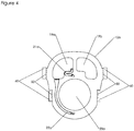
- Structural plate 10a also includes contacting features (not shown) for locating and holding seals (e.g., o-ring gaskets) and in an especially preferred embodiment, contacting means 50 for locating and interlocking with similar contacting means on one or more external reinforcing means 60 at desired points of contact on its peripheral edge, as shown in Figure 4 .
- Similar supporting means, shown as 70 in Figures 1 and 2 can be included on end pressure plates 11 and optionally on the one or more intermediate pressure plates 12, for supporting and aligning the external reinforcing means.
- the structural plates are made of a suitable electrically insulating plastic or fiber-reinforced plastic.
- Structural plates 10a and 10b shown in Figure 3 correspond to cathode (hydrogen) structural plates 10a and anode structural plates 10b in Figures 1 and 2 .
- the anode (oxygen) structural plate 10b is the mirror image of the cathode (hydrogen) structural plate 10a.
- Figure 3 also shows features for a particularly preferred feed water addition system, which comprises entry passages in one or more of the end pressure plates 11 and/or one or more intermediate pressure plates 12, which are in fluid communication on one end with an external feed water source, typically with feed water purification, e.g., by reverse osmosis and/or ion exchange, and by filters such as carbon filters, and on the other end with one or more feed water manifolds formed by feed water openings 102 in structural plates 10.
- Feed water openings 102 in turn further fluidly communicate in one or more of the structural plates 10 with one or more of the first and second degassing chambers 19a and 19b via water flow passages 103.
- water flow passages 103 in cathode structural plates 10a are in fluid communication with hydrogen degassing chamber 19a
- water flow passages 103 in anode structural plates 10b are in fluid communication with oxygen degassing chamber 19b, or vice-versa, such that water flow passages connect to opposite degassing chambers in adjacent structural plates.
- separate feed water passages are used to add liquids to hydrogen degassing chamber 19a and oxygen degassing chamber 19b.
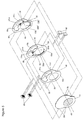
- Figure 5 shows an exploded view of a preferred embodiment; only three structural plates 10a, 10b, and 10c and one end pressure plate 11 are shown; other components, such as cell components, seals, etc. are not shown for clarity.
- Four external reinforcing means 60 are used, each comprising a main body comprised of, for example, metal beams or tubes which run along the length of the electrolyser module. Two external reinforcing means 60 are used on each side of the module; it is to be understood that although the structural plates and end pressure plate are shown as exploded assembly views, each reinforcing means 60 is represented as a non-exploded view in Figure 5 , for overall clarity.
- the external reinforcing means also could be "U"-shaped or “ring”-shaped, in which case in the preferred embodiment illustrated in Figure 5 there would only two external reinforcing means at two different heights, each contacting the structural plates on either side.
- the external reinforcing means do not necessarily have to cover the full length of the electrolyser module; for example, if there is an intermediate pressure plate, it may be convenient to have each set of external reinforcing means cover from one end pressure plate to the intermediate pressure plate.
- the contacting means of the external reinforcing means 60 that contact the structural plates are comprised of features such as machined teeth that interlock with corresponding similarly-shaped contacting means 50 defined on the side walls of the structural plates.
- the contacting means of the external reinforcing means can be, e.g., machined directly into the main body, or e.g., machined into a plate and attached to the main body.
- the teeth are angled to provide contact in multiple directions, thereby providing multi-directional support and strength.
- the external reinforcing means therefore mitigate outward displacement of the plastic structural plate material in response to fluid pressure within the electrolyser module.
- a key benefit is stress relief in the middle sections of the structural plate, where complex features such as at the entrance of the gas-liquid passage would otherwise be focal points for stress development at higher operating pressures (e.g., 25 bar).
- the external reinforcing means also enable minimization of plastic material around the periphery of the structural plates, reducing cost, part size and weight, and shot size for injection molding.
- the external reinforcing means preferably are located in a symmetrical manner, with contact points being mirror images on opposite sides of the peripheries of the structural plates.
- the vertical distance between the two external reinforcing means on each side of the electrolyser module is therefore about one-third the height of the structural plates.
- the external reinforcing means for all the embodiments described herein have significantly better mechanical properties (e.g., significantly higher strength and elastic modulus) than the plastic or fiber reinforced plastic comprising the bodies of the structural plates, and preferably are easily installed, readily available, and low cost.
- Preferred materials are metals, plated metals or coated metals (the term "metals” is to be understood to include metals and metal alloys), most preferably steel or stainless steel, which are commonly available as tubes or beams, and which provide good mechanical properties at relatively low cost.
- the external reinforcing means are straightforwardly installed after assembly of the electrolyser module, and are attached to one or more of the end pressure plates and the one or more intermediate pressure plates.
- the points of connection of the external reinforcing means to the end pressure plates preferably are electrically insulated.
- Installation involves holding in place the one or more external reinforcements on one side of the electrolyser module by attaching (pinning) them to one or more of the end pressure plates and the one or more intermediate pressure plates, and then attaching the corresponding one or more external reinforcing means on the other side of the electrolyser module in a similar manner, except using one or more adjustment mechanisms (e.g., threaded adjustments) to make adjustments in place to achieve good contact of the contacting means of the external reinforcing means and the structural plates. Also, some pre-stressing may be applied to the structural plates through the adjustment mechanisms.
- adjustment mechanisms e.g., threaded adjustments
- an electrolyser stack comprises a plurality of structural plates each having a sidewall extending between opposite end faces with a half cell chamber opening, with at least two header flow passage openings and at least one footer flow passage opening extending through each structural plate between its opposite end faces.
- the structural plates are arranged in face to face juxtaposition between opposite end pressure plates.
- Each half cell chamber opening at least partially houses electrolytic half cell components comprising at least an electrode, a bipolar plate in electrical communication with the electrode, and a membrane communicating with the electrode for providing ionic conduction.
- the structural plates and half cell components therefore define an array of series connected electrolytic cells.
- the structural plates also define, at least when in face to face juxtaposition, passages for fluid flow inside the electrolyser stack.
- the electrolyser stack further comprises at least one external reinforcing means contacting at least some of the structural plates for mitigating outward displacement of the structural plates. At least some of the structural plates further define contacting means for aligning and achieving multi-directional contact with the external reinforcing means.
- the electrolyser stack can further comprise at least one intermediate pressure plate interspersed between the structural plates along the length of the electrolyser stack.
Landscapes
- Chemical & Material Sciences (AREA)
- Engineering & Computer Science (AREA)
- Chemical Kinetics & Catalysis (AREA)
- Electrochemistry (AREA)
- Materials Engineering (AREA)
- Metallurgy (AREA)
- Organic Chemistry (AREA)
- Inorganic Chemistry (AREA)
- Electrolytic Production Of Non-Metals, Compounds, Apparatuses Therefor (AREA)
- Electrically Driven Valve-Operating Means (AREA)
Description
- The present invention relates to the design of water electrolysers for the production of hydrogen and oxygen gases at elevated pressures, and more particularly, to alkaline and polymer electrolyte membrane (PEM) type electrolyser stacks and electrolyser modules with enhanced capability for operation at elevated pressures, and components therefor.
- Electrolysers use electricity to transform reactant chemicals to desired product chemicals through electrochemical reactions, i.e., reactions that occur at electrodes that are in contact with an electrolyte. Hydrogen is a product chemical of increasing demand for use in chemical processes, and also potentially for use in hydrogen vehicles and equipment powered by hydrogen fuel cell engines or hydrogen internal combustion engines (or hybrid hydrogen vehicles, also partially powered by batteries). Water electrolysers, which produce hydrogen and oxygen from water and electricity, are the most common type of electrolyser used for production of gaseous hydrogen as the main product. The most common types of commercial water electrolysers are alkaline water electrolysers (AWE) and polymer electrolyte membrane (PEM) water electrolysers.
- As used herein, the terms "half cell", "half electrolysis cell" and equivalent variations thereof refer to a structure comprising one electrode and its corresponding half cell chamber that provides space for gas-liquid (or gas) flow out of the half cell. The term "cathode half cell" refers to a half cell containing a cathode, and the term "anode half cell" refers to a half cell containing an anode.
- As used herein, the terms "cell", "electrolysis cell" and equivalent variations thereof refer to a structure comprising a cathode half cell and an anode half cell. A cell also includes a separator membrane (referred to herein after as a "membrane"), typically located between, and in close proximity to, in contact with, or integral with, the cathodes and anodes. The functionality of the membrane is to maintain the hydrogen and oxygen gases produced separate and of high purity, while allowing for ionic conduction of electricity between the anode and cathode. A membrane therefore defines one side of each half cell. The other side of each half cell is defined by an electronically conducting solid plate, typically comprised of metal, carbon, carbon-polymer composite, or combinations thereof, and generally known as a bipolar plate. The functionality of the bipolar plate is to maintain the fluids in adjacent half cell chambers of adjacent cells separate, while conducting current electronically between the adjacent cells. Each half cell chamber also contains an electronically conducting component generally known as a current collector or current carrier, to conduct current across the half cell chamber, between the electrode and the bipolar plate.
- As used herein, the terms "cell stack", "electrolyser stack", "stack", or equivalent variations thereof refer to structures used for practical (commercial) water electrolysers comprising multiple cells, in which the cells typically are electrically connected in series (although designs using cells connected in parallel and/or series also are known), with bipolar plates physically separating but providing electrical communication between adjacent cells. Gas-liquid (i.e., hydrogen-liquid and oxygen-liquid) mixtures are collected from individual half-cells in header flow passages (top flow manifolds), which run lengthwise along the stack, above the cells. The header flow passages fluidly communicate with respective gas-liquid discharge passages extending through the electrolyser stack and in fluid communication with external piping or tubing, which in turn fluidly communicate with external gas-liquid separation vessels. Operations performed in the external gas-liquid separation vessels include gas-liquid separation, and optionally feed water addition and liquid mixing. Degassed liquid is returned to the cell stack via external piping or tubing, which is in fluid communication with respective degassed liquid return passages extending through the electrolyser stack. Degassed liquid is distributed to individual half-cells via footer flow passages (bottom flow manifolds), which run lengthwise along the stack, underneath the cells. In some PEM electrolyser stacks, the hydrogen side is operated without circulating liquid, in which case the hydrogen side header flow passage(s) and discharge passage(s) would carry hydrogen gas, and in which case there would be no requirement for a gas-liquid separation circuit on the hydrogen side.
- As used herein, the term "electrolyser module" refers to the combination of an electrolyser stack and gas-liquid separation spaces in the same structure, which typically is of the filter press type. Further, the term "electrolyser module" as used herein may refer to an alkaline electrolyser module or a PEM electrolyser module. We previously disclosed designs for an alkaline electrolyser module in
US 8,308,917 , and for a PEM electrolyser module inUS 2011/0042228 . - As used herein, the term "structural plate" refers to a body having a sidewall extending between opposite end faces with a half cell chamber opening, and in the case of an electrolyser module, additionally at least one degassing chamber opening extending through the structural plate between the opposite end faces. An electrolyser stack or an electrolyser module typically is constructed using a series of structural plates to define alternately cathode and anode half cell chambers, fluid flow passages, and in the case of an electrolyser module, at least one degassing chamber, and respective gas-liquid flow passages and respective degassed liquid flow passages extending between the one or more degassing chambers and the corresponding half cell chambers. The structural plates are arranged in face to face juxtaposition between opposite end pressure plates, optionally with at least one intermediate pressure plate interspersed between the structural plates along a length of the electrolyser stack or electrolyser module, to form a filter press type structure. The end pressure plates and intermediate pressure plates can be made of, e.g., one or more of steel, stainless steel, nickel-plated steel, nickel-plated stainless steel, nickel and nickel alloy. The structural plates also hold functional components, which may include, for example, cathodes, anodes, separator membranes, current collectors, and bipolar plates, in their appropriate spatial positions and arrangement.
- The structural plates are made of a suitable electrically insulating plastic or fiber-reinforced plastic that is inert to electrolyte (e.g., in the case of an alkaline electrolyser module, an aqueous solution of 25% to 35% KOH at elevated temperatures) or water (in the case of a PEM electrolyser module) and gases (e.g., oxygen, hydrogen, nitrogen). Examples of suitable plastics include polyoxymethylene (POM), polypropylene, polyphenylene oxide (PPO), polyphenylene sulphide (PPS) and the like, and in particular, polysulfone. The structural plates are manufactured by processes such as machining, and more preferably, injection molding, sometimes with some post-machining. Thus, the plates are lightweight, non-conducting, resistant to the operating environment, and amenable to simple and relatively low cost fabrication.
- Generally contemplated operating pressures of electrolyser modules and electrolyser stacks lie between atmospheric pressure and 30 barg, and more typically up to 10 barg, depending on the application requirements. Higher pressure operation, for example, in the range of 17 to 30 barg, is advantageous as it enables direct filling of commonly-used gas storage vessels, or a reduced number of mechanical compression stages when filling higher pressure storage. Older electrolyser stack designs utilized steel structural plates, which enabled operation at elevated pressures, e.g., 30 barg, but presented other challenges, such as very high weight, the need for electrical insulation, and potential for corrosion. For modern, "advanced" electrolyser stack and electrolyser module designs utilizing structural plates made of plastic, higher pressure operation presents challenges with regard to mechanical integrity of the structural plates, especially over the long term and for large scale electrolyser modules and electrolyser stacks. Pressure containment means, such as a pressure vessel or a load bearing reinforcing support completely surrounding an electrolyser stack are known in the art (e.g.,
US 6,153,083 ,US 7,314,539 ), but preferably are to be avoided in order to maintain inherent design simplicity, ease of implementation, compactness, lightweight, and low capital cost. The structural plates could be made significantly more massive, but this approach is impractical and also preferably to be avoided, due to correspondingly significantly increased cost, size, weight, and difficulty of injection molding. The approach of reinforcing each structural plate may be preferred if it can be implemented simply, without significantly adverse effects on ease of assembly, compactness, weight and cost. -
US 7,332,063 discloses an approach to reinforcement of individual structural plates in an electrolyser stack in which each structural plate is supported externally by a surrounding external wound fibreglass reinforcement, in order to withstand higher operating pressures. The approach of imposing a tight-fitting external support around the external periphery of structural plates is best suited to circular shapes, such as that contemplated inUS 7,332,063 . However, for large structural plates with complex irregular shapes, this type of external support would be less effective and more difficult and expensive to install. -
US 6 383 347 teaches an electrolyser structure in which the frames are comprised of rubber gasket seal material, which in practice are supported by metallic electrode plates. The operating pressures are limited to near-atmospheric pressure. Metal channel supports are attached to the electrode plates to maintain the gaps for fluid flow and thus to avoid excessive squeezing of the rubber gasket seal material comprising the structural frames and closing of the gaps for fluid flow. -
CA 1 076 994 A teaches a conventional electrolyser stack design with manifolds running the full length of the stack for feeding and collecting the fluid flows into and out of all of the electrochemical cells. External alignment means are disclosed, which are external members integral with the cell frames to fit and rest on a support bar. This construction facilitates assembly together of the cell frames. This functionality is that of a support and alignment stand. - Thus, what is needed is a simple, easily-implemented, cost effective approach to reinforcement of structural plates for electrolyser modules and electrolyser stacks, especially large-scale electrolyser modules and electrolyser stacks, in order to enable them to operate at higher pressures.
- The present invention is defined by the appended claims.
- An electrolyser module comprising a plurality of structural plates of complex irregular shape, each structural plate having a sidewall extending between opposite end faces with a half cell chamber opening and at least two degassing chamber openings extending through the structural plate between the opposite end faces. The structural plates are arranged in face to face juxtaposition in a longitudinal stacking direction between opposite end pressure plates. Each half cell chamber opening at least partially houses electrolytic half cell components comprising at least an electrode, a bipolar plate in electrical communication with the electrode, and a membrane communicating with the electrode for providing ionic conduction. The structural plates and half cell components define an array of series connected electrolytic cells surmounted by at least one degassing chamber. The structural plates define, at least when in face to face juxtaposition, passages for fluid flow inside the electrolyser module. The electrolyser module further comprises at least one external reinforcing means contacting at least some of the structural plates for mitigating outward displacement of the structural plates in a direction transverse to the longitudinal stacking direction. At least some of the structural plates further define contacting means on the side walls of said at least one of said structural plates for achieving contact with the at least one external reinforcing means at points of contact on said side walls of said at least one of said structural plates; wherein said at least one external reinforcing means further comprise at least one contacting means that interlocks with said at least one contacting means on the sidewalls of said at least one of said structural plates. This construction mitigates outward displacement of the structural plate in a radial direction transverse to the longitudinal stacking direction.
- A structural plate for an electrolyser module having a sidewall extending between opposite end faces with a half cell chamber opening and at least two degassing chamber openings extending through said structural plate between said opposite end faces. The structural plate defines, at least when in face-to-face juxtaposition in a longitudinal stacking direction with another structural plate, an end pressure plate, or an intermediate pressure plate, passages for fluid flow inside the electrolyser module. The structural plate further defines at least one contacting means at points of contact on the sidewalls of said at least one of said structural plates to provide contact and interlocking with at least one contacting means on the one or more external reinforcing means.
- An electrolyser stack comprising a plurality of structural plates, each structural plate having a sidewall extending between opposite end faces with a half cell chamber opening, at least two header flow passage openings and at least one footer flow passage opening extending through the structural plate between said opposite end faces. The structural plates are arranged in face to face juxtaposition between opposite end pressure plates. Each half cell chamber opening at least partially houses electrolytic half cell components comprising at least an electrode, a bipolar plate in electrical communication with the electrode, and a membrane communicating with the electrode for providing ionic conduction. The structural plates and half cell components define an array of series connected electrolytic cells. The structural plates define, at least when in face to face juxtaposition in a longitudinal stacking direction, passages for fluid flow inside the electrolyser stack. The electrolyser stack further comprises one or more external reinforcing means contacting at least some of the structural plates for mitigating outward displacement of the structural plates in a direction transverse to the longitudinal stacking direction. At least one of said structural plates further define contacting means on the sidewalls of said at least one of said structural plates for achieving contact with the one or more external reinforcing means at points of contact on said side walls of said structural plates, wherein said at least one external reinforcing means further comprises at least one contacting means that interlocks with said at least one contacting means on the sidewalls of said at least one of said structural plates.
- Preferred embodiments of the present invention are described below with reference to the accompanying illustrations in which:
-
Figure 1 is an exploded view of about half of an alkaline electrolyser module in accordance with the present invention; -
Figure 2 is an exploded view of about half of a PEM electrolyser module in accordance with the present invention; -
Figure 3 is a front elevation showing the front face of an embodiment of structural plates for use with external reinforcing means, as well as a preferred embodiment of feed water addition features, in accordance with the present invention; -
Figure 4 is a front elevation showing the front face of an embodiment of a structural plate and external reinforcing means in accordance with the present invention; -
Figure 5 is an isometric view showing the front faces of an embodiment of structural plates, an end pressure plate and external reinforcing means for an electrolyser module in accordance with the present invention; -
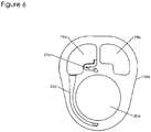
Figure 6 is a front elevation showing the front face of an embodiment of a structural plate for an electrolyser module without external reinforcing means in accordance with a prior design; and, -
Figure 7 is an exploded view of an embodiment of a cathode drain in accordance with the present invention, showing cathode drain features in a series of three adjacent structural plates. - In the present invention, one or more external reinforcing means in contact with at least some of the structural plates are used to increase the internal fluid pressure holding capability of an electrolyser stack or electrolyser module, while at the same time enabling reduction in plastic material requirements and improving the creep resistance and structural plate lifetime. The external reinforcing means have significantly better mechanical properties (e.g., significantly higher strength and elastic modulus) than the plastic or fiber-reinforced plastic material of the structural plates, and preferably are easily installed, readily available, and low cost. Contact between the external reinforcing means and each of the structural plates is achieved through contacting means comprised of interlocking features defined on the peripheral edges of the structural plates and on the external reinforcing means.
- An alkaline electrolyser module in accordance with an aspect of the present invention is shown generally at 100 in
Figure 1. Figure 1 shows about half of an alkaline electrolyser module with 4 cells for illustrative purposes only; the other half of the electrolyser module would be a mirror image (on either side offeature 12, which in this case represents the midpoint of the electrolyser module). In practice, typically greater numbers of cells would be incorporated.Alkaline electrolyser module 100 includes structural plates 10,end pressure plates 11,anodes 13,cathodes 14,membranes 15,current carriers 16,bipolar plates 17, and optionally, one or moreintermediate pressure plates 12 interspersed between structural plates along the length of the electrolyser module. The structural plates 10,end pressure plates 11 andintermediate pressure plates 12 comprise at least a body having a sidewall extending between opposite end faces. There are two main types of structural plates 10: cathodestructural plates 10a and anodestructural plates 10b. Additionally, specialstructural plates intermediate pressure plate 12 and also optionally adjacent to either or both of theend pressure plates 11, respectively, e.g., to help to accommodate cooling conduits (e.g., cooling tubes or cooling coils). (As used herein, the term "plate" refers to structural plates, special structural plates, end pressure plates and intermediate pressure plates.) Suitable seals (e.g., o-ring gaskets, not shown) also are understood to be included. At least some ofstructural plates structural plates Figure 1 for better clarity of the electrolyser module assembly, they are shown in other Figures, and key elements of an especially preferred embodiment are shown inFigure 1 , namely: i) contacting means 50 in the structural plates, for achieving multi-directional contact with external reinforcing means; and, ii) supportingmeans 70 in the intermediate pressure plates and the end pressure plates, for supporting and aligning external reinforcing means. Not all of the structural plates may necessarily require external reinforcement; for example, if special structural plates are used, especially at moderate pressures, they may not require external reinforcing means, since they lack fluid flow passages (i.e., they contain more material), and also they are somewhat inherently reinforced by the adjacentend pressure plate 11 orintermediate pressure plates 12. Accordingly, some of the structural plates, e.g., one or more special structural plates, may be made without contactingmeans 50 and used without external reinforcing means. Also, structural plates adjacent to an end pressure plate or an intermediate pressure plate may be directly mechanically reinforced by embedding them into the adjacent end pressure plate or intermediate pressure plate. However, there is little benefit to not utilizing external reinforcing means with certain of the structural plates, since the external reinforcing means are readily available if they are to be used with other structural plates, and use of the external reinforcing means also helps to align the structural plates in question with the rest of the electrolyser module assembly. -
Alkaline electrolyser module 100 thus comprises a plurality ofelectrolysis cells 18 and associated degassing chambers 19. Theelectrolysis cells 18 preferably are located at the bottom part of theelectrolyser module 100, and the associated degassing chambers 19 preferably are located at the top part of theelectrolyser module 100, surmounting theelectrolysis cells 18. The electrolysis cells comprise cathode and anodehalf cell chambers cathode 14, ananode 13, amembrane 15, andcurrent collectors 16. More than onecurrent collector 16 can be used perhalf cell chamber 20a and/or 20b.Bipolar plates 17 physically separate, and provide electrical communication between, adjacent cells. The membrane is in communication with each of the electrodes for providing ionic conduction.End pressure plates 11 andintermediate pressure plates 12 optionally include suitably coated or plated electrically conducting areas orseparate parts End pressure plates 11 andintermediate pressure plates 12 can be made of, e.g., one or more of steel, stainless steel, nickel-plated steel, nickel-plated stainless steel, nickel and nickel alloy, or other plated, coated, or non-plated, non-coated metals (the term "metals" is to be understood to include metals and metal alloys). - As shown in
Figure 1 , each cathodehalf cell chamber 20a is in direct fluid communication with thehydrogen degassing chamber 19a via a gas-liquid flow passage 21a, and a degassedliquid flow passage 22a. Similarly, each anodehalf cell chamber 20b is in direct fluid communication with theoxygen degassing chamber 19b via a gas-liquid flow passage 21b, and a degassedliquid flow passage 22b. Separated hydrogen gas exits through hydrogengas discharge passage 25, which extends radially through to the hydrogen degassing chamber; separated oxygen gas exits through separated oxygengas discharge passage 26, which extends radially through to the oxygen degassing chamber.Gas discharge passages intermediate pressure plate 12, or in one or both of theend pressure plates 11. Feed water is introduced to one or both of the hydrogen andoxygen degassing chambers intermediate pressure plates 12 or in one or both of theend pressure plates 11. Electrical current is supplied to the cell portion ofelectrolyser module 100 by, for example, a DC power supply, most commonly via positive and negative electrical connections to endpressure plates 11, and optionally with a non-current carrying electrical ground connection tointermediate pressure plate 12 at the midpoint ofelectrolyser module 100. Separate liquid drains 47a and 47b for each of the hydrogen side (cathode drain) and the oxygen side (anode drain) respectively, are located at the bottom of one or more of theintermediate pressure plates 12 and theend pressure plates 11. The liquid drains are in fluid communication with either the cathode half cell chambers and hydrogen degassing chamber, or the anode half cell chambers and oxygen degassing chamber through a series of draining conduits in the structural plates, as described below. The liquid drains drain liquid (electrolyte) from the electrolyser module, for purposes such as long term shut down, maintenance, transport, sampling, etc., or for purposes such as removing bleed stream(s), to maintain the purity of the liquid (electrolyte) in the electrolyser module. The drains comprise two separate drains, a cathode drain for the cathode (hydrogen) portions of the electrolyser module, and an anode drain for the anode (oxygen) portions of the electrolyser module. Optionally, a bleed stream of liquid (electrolyte) can be taken from inside alkalinewater electrolyser module 100 via one or both ofliquid drains - In a first embodiment of the liquid drains, each of the cathode drain and the anode drain comprise a plurality of connecting draining passages connecting the bottom portions of either each of the cathode half cell chambers or each of the anode half cell chambers to one or more draining manifolds. Note that by draining the half cell chambers, the corresponding degassing chambers also are drained, since they are in fluid communication with the half cell chambers through the degassed liquid passages and the gas-liquid passages. The cathode drain and the anode drain can be, but are not necessarily, similar. The cathode drain will be described here for illustrative purposes. The cathode draining passages comprise long passages with relatively small cross sectional areas connecting the bottom portion of the cathode half cell chambers with one or more cathode draining manifolds. The cathode draining manifolds are located below the cathode half cell chambers in order that draining can be achieved by gravity head, and extend at least part way along the length of the electrolyser module. The lengths of the draining passages for the cathode half cells can be extended by using paths comprised in more than one structural plate. In the current embodiment, the draining passages are internal passages near the bottom part of the cathode half cell chamber, which then become surface passages that follow a long downward path in order to render stray current flows during operation negligible. The passage then travels through one of the adjacent anode plates to the next cathode plate, where it once again becomes a surface passage with a long path, before joining one of the cathode draining manifolds. More than one cathode draining manifold can be used in order to further limit stray current flows. The one or more cathode draining manifolds connect to a draining point. The draining point comprises a draining port with a valve, located in the bottom portion of one of the intermediate pressure plates or one of the end pressure plates. There can be more than one draining point in the electrolyser module.
- In the second embodiment, each of the cathode drain and the anode drain also comprise draining channels for each half cell. Preferably, similar approaches are used for both the cathode drain and the anode drain. The cathode drain will be described here for illustrative purposes. The main features of the cathode drain are shown in
Figure 7 , which shows a series of three adjacent structural plates (two cathode structural plates and one anode structural plate) in the electrolyser module. The starting point of thecathode draining passage 80 for each cathode half cell is located in the degassedliquid passage 22a, near its point of connection to the cathode half cell chamber opening 20a. (In an alternative configuration (not shown), thecathode draining passage 80 is connected directly at or near the bottom of the cathode half cell chamber opening 20a.) Thus, the starting point of thecathode draining passage 80 lies underneath the cathode half cell chamber. Thecathode draining passage 80 initially is an internal passage, passing through the thickness of the cathodestructural plate 10a to the opposing face of adjacent anodestructural plate 10b, where it becomes a surface passage that creates a long path in order to render stray current flows during operation negligible. The periphery of the area defined by the surface passages in the face of anodestructural plate 10b is sealed, preferably by an o-ring (not shown) that is seated in a holding feature (not shown). Thecathode draining passage 80 then once again becomes an internal passage, passing through the thickness of anodestructural plate 10b to degassedliquid passage 22a in the adjacent cathodestructural plate 10a. This multi-structural plate configuration is then repeated until a draining point is reached. The draining point comprises a draining port with internal channels connecting to a valve, located in the bottom portion of one of theintermediate pressure plates 12 or one of theend pressure plates 11. There can be more than one draining point in the electrolyser module. An advantage of the second embodiment is that there is no requirement for enlarging the bottom portions of the structural plates. - A PEM electrolyser module in accordance with an aspect of the present invention is shown generally at 200 in
Figure 2. Figure 2 shows about half of an electrolyser module with 4 cells for illustrative purposes only; the other half of the electrolyser module would be a mirror image (on either side offeature 12, which in this case represents the midpoint of the electrolyser module). In practice, typically greater numbers of cells would be incorporated.PEM electrolyser module 200 includes structural plates 10,end pressure plates 11, membrane-electrode assemblies (MEA's) 33, optionallyelectrode backing layers current carriers 34,bipolar plates 35 and optionally, one or moreintermediate pressure plates 12. The structural plates 10,end pressure plates 11 andintermediate pressure plates 12 comprise at least a body having a sidewall extending between opposite end faces. A typical MEA consists of a membrane and electrodes coated onto opposite faces of the membrane; a cathode coated onto one face of the membrane, and an anode coated onto the opposite face of the membrane. Thus, the membrane is in communication with each of the two electrodes for providing ionic conduction. In some embodiments, theelectrode backing layers MEA 33. In the embodiment shown inFigure 2 , there are two main types of structural plates 10: cathodestructural plates 10a and anodestructural plates 10b. Additionally, specialstructural plates intermediate pressure plate 12 and theend pressure plates 11, respectively, e.g., to help accommodate cooling conduits (e.g., cooling tubes or cooling coils). Suitable seals (e.g., o-ring gaskets, not shown) also are understood to be included. At least some of structural plates 10 and specialstructural plates Figure 2 for better clarity of the electrolyser module assembly, key elements of an especially preferred embodiment are shown inFigure 2 , namely contacting means 50 in the structural plates, for achieving multi-directional contact with external reinforcing means, and supportingmeans 70 in the intermediate pressure plate and the end pressure plates, for supporting and aligning external reinforcing means. Not all of the structural plates may necessarily require external reinforcement; for example, if special structural plates are used, especially at moderate pressures, they may not require external reinforcing means, since they lack fluid flow passages (i.e., they contain more material), and also they are somewhat inherently reinforced by the adjacentend pressure plate 11 orintermediate pressure plates 12. Accordingly, some of the structural plates, e.g., one or more special structural plates, may be made without contactingmeans 50 and used without external reinforcing means. Also, structural plates adjacent to an end pressure plate or an intermediate pressure plate may be directly mechanically reinforced by embedding them into the adjacent end pressure plate or intermediate pressure plate. However, there is little benefit to not utilizing external reinforcing means with certain of the structural plates, since the external reinforcing means are readily available if they are to be used with other structural plates, and use of the external reinforcing means also helps to align the structural plates in question with the rest of the electrolyser module assembly. -
PEM electrolyser module 200 thus comprises a plurality of electrolysis cells and associatedhydrogen degassing chamber 19a andoxygen degassing chamber 19b. ThePEM electrolysis cells 38 preferably are located at the bottom part of theelectrolyser module 200, and the associateddegassing chambers electrolyser module 200, surmounting thePEM electrolysis cells 38. The electrolysis cells comprise cathode and anodehalf cell chambers MEA 33, optionallyelectrode backing layers current collectors 34.Bipolar plates 35 physically separate and provide electrical communication between adjacent cells.End pressure plates 11 andintermediate pressure plates 12 optionally include suitably coated or plated electrically conducting areas orseparate parts End pressure plates 11 andintermediate pressure plates 12 can be made of, e.g., one or more of steel, stainless steel, plated or coated steel, plated or coated stainless steel, or other plated, coated or non-plated, non-coated metals (the term "metals" is to be understood to include metals and metal alloys). - As shown in
Figure 2 , each cathodehalf cell chamber 20a is in direct fluid communication with thehydrogen degassing chamber 19a via a gas-liquid flow passage 21a, and a degassedliquid flow passage 22a. Similarly, each anodehalf cell chamber 20b is in direct fluid communication with theoxygen degassing chamber 19b via a gas-liquid flow passage 21b, and a degassedliquid flow passage 22b. Separated hydrogen gas exits through hydrogengas discharge passage 25, which extends radially through to the hydrogen degassing chamber; separated oxygen gas exits through separated oxygengas discharge passage 26, which extends radially through to the oxygen degassing chamber.Gas discharge passages intermediate pressure plate 12, or in one or both of theend pressure plates 11. Feed water is introduced to one or both of the hydrogen andoxygen degassing chambers intermediate pressure plate 12 or in one or both of theend pressure plates 11. Electrical current is supplied to the cell portion ofelectrolyser module 200 by, for example, a DC power supply, most commonly via positive and negative electrical connections to endpressure plates 11, and optionally with a non-current carrying electrical ground connection tointermediate pressure plate 12 at the midpoint ofelectrolyser module 200. Separate liquid drains 47a and 47b for each of the hydrogen (cathode) side and the oxygen (anode) side respectively, are located at the bottom of one or more of theintermediate pressure plates 12 and theend pressure plates 11. The liquid drains are in fluid communication with either the cathode half cell chambers and hydrogen degassing chamber or the anode half cell chambers and oxygen degassing chamber through respective series of draining conduits in the structural plates, as described below. The liquid drains drain liquid (water) from the PEM water electrolyser module, for purposes such as long term shut down, maintenance, transport, sampling, etc. Optionally, a bleed stream of relatively impure liquid (water) can be taken from inside PEMwater electrolyser module 200 via one or both ofliquid drains PEM water electrolyser 200 via one or both ofliquid drains PEM water electrolyser 200, e.g., along with or in place of new feed water. The water purification means can be that used to purify feed water. - In a first embodiment of the liquid drains, each of the cathode drain and the anode drain comprise a plurality of connecting draining passages connecting the bottom portions of either each of the cathode half cell chambers or each of the anode half cell chambers to one or more draining manifolds. Note that by draining the half cell chambers, the corresponding degassing chambers also are drained, since they are in fluid communication with the half cell chambers through the degassed liquid passages and the gas-liquid passages. The cathode drain and the anode drain can be, but are not necessarily, similar. The cathode drain will be described here for illustrative purposes. The cathode draining passages comprise passages between the bottom portion of the cathode half cell chambers and one or more cathode draining manifolds. The cathode draining manifolds are located below the cathode half cell chambers in order that draining can be achieved by gravity head, and extend at least part way along the length of the electrolyser module. In the current embodiment, the draining passages are internal passages near the bottom part of the cathode half cell chamber, which then become surface passages. The passage then extends through one of the adjacent anode plates to the next cathode plate, where it once again becomes a surface passage, before joining to one of the cathode draining manifolds. More than one cathode draining manifold can be used. The one or more cathode draining manifolds connect to a draining point. The draining point comprises a draining port with a valve, located in the bottom portion of one of the intermediate pressure plates or one of the end pressure plates. There can be more than one draining point in the electrolyser module.
- In a second embodiment, each of the cathode drain and the anode drain also comprise draining channels for each half cell. Preferably, similar approaches are used for both the cathode drain and the anode drain. The cathode drain will be described here for illustrative purposes. The main features of the cathode drain are shown in
Figure 7 , which shows a series of three adjacent structural plates (two cathode structural plates and one anode structural plate) in the electrolyser module. The starting point of thecathode draining passage 80 for each cathode half cell is located in the degassedliquid passage 22a, near its point of connection to the cathode half cell chamber opening 20a. (In an alternative configuration (not shown), thecathode draining passage 80 is connected directly at or near the bottom of the cathode half cell chamber opening 20a.) Thus, the starting point of thecathode draining passage 80 lies underneath the cathode half cell chamber. Thecathode draining passage 80 initially is an internal passage, passing through the thickness of the cathodestructural plate 10a to the opposing face of adjacent anodestructural plate 10b, where it becomes a surface passage. The periphery of the area defined by the surface passages in the face of anodestructural plate 10b is sealed, preferably by an o-ring (not shown) that is seated in a holding feature (not shown). Thecathode draining passage 80 then once again becomes an internal passage, passing through the thickness of anodestructural plate 10b to degassedliquid passage 22a in the adjacent cathodestructural plate 10a. This multi-structural plate configuration is then repeated until a draining point is reached. The draining point comprises a draining port with internal channels connecting to a valve, located in the bottom portion of one of theintermediate pressure plates 12 or one of theend pressure plates 11. There can be more than one draining point in the electrolyser module. An advantage of the second embodiment is that there is no requirement for enlarging the bottom portions of the structural plates. - If the
electrolyser module chambers intermediate pressure plate 12,end pressure plates 11 and specialstructural plates intermediate pressure plate 12 andend pressure plates 11, at least when in face-to-face juxtaposition with adjacent specialstructural plates structural plates intermediate pressure plate 12,end pressure plate 11, respectively, orstructural plates degassing chambers intermediate pressure plate 12 or endpressure plate 11. Illustrative examples are shown inFigures 1 and2 : (i) features 28a and 28b in specialstructural plates 10c; (ii) features 29a and 29b in specialstructural plates 10d; and, (iii)feature 40, which is tube or pipe in liquid communication with the lower portion of the hydrogen degassing chamber and the oxygen degassing chamber via respective interior passages inintermediate pressure plate 12; (iv) features 45a and 45b inintermediate pressure plate 12 and features 46a and 46b inend pressure plate 11.Features Figures 1 and2 , and further that appropriate combinations offeatures features structural plates intermediate pressure plate 12, respectively. Such liquid communication betweendegassing chambers - Structural plates for an electrolyser module in accordance with an aspect of the present invention are shown in
Figure 3. Figure 3 shows a preferred embodiment in whichstructural plate 10a defines one half cell chamber opening 20a and two degassingchamber openings Structural plate 10a defines one or more gas-liquid flow passages 21a, which provide direct fluid communication between the top part of the half cell chamber opening 20a to one of thedegassing chamber openings Structural plate 10a further defines one or more degassedliquid flow passages 22a, which provide direct fluid communication between the bottom part of the half cell chamber opening 20a to one of thedegassing chamber openings Structural plate 10a also includes contacting features (not shown) for locating and holding seals (e.g., o-ring gaskets) and in an especially preferred embodiment, contacting means 50 for locating and interlocking with similar contacting means on one or more external reinforcingmeans 60 at desired points of contact on its peripheral edge, as shown inFigure 4 . Similar supporting means, shown as 70 inFigures 1 and2 , can be included onend pressure plates 11 and optionally on the one or moreintermediate pressure plates 12, for supporting and aligning the external reinforcing means. The structural plates are made of a suitable electrically insulating plastic or fiber-reinforced plastic. Examples of suitable plastics include polyoxymethylene (POM), polypropylene, polyphenylene oxide (PPO), polyphenylene sulphide (PPS) and the like, and in particular, polysulfone.Structural plates Figure 3 correspond to cathode (hydrogen)structural plates 10a and anodestructural plates 10b inFigures 1 and2 . The anode (oxygen)structural plate 10b is the mirror image of the cathode (hydrogen)structural plate 10a. -
Figure 3 also shows features for a particularly preferred feed water addition system, which comprises entry passages in one or more of theend pressure plates 11 and/or one or moreintermediate pressure plates 12, which are in fluid communication on one end with an external feed water source, typically with feed water purification, e.g., by reverse osmosis and/or ion exchange, and by filters such as carbon filters, and on the other end with one or more feed water manifolds formed byfeed water openings 102 in structural plates 10.Feed water openings 102 in turn further fluidly communicate in one or more of the structural plates 10 with one or more of the first andsecond degassing chambers water flow passages 103. Typically,water flow passages 103 in cathodestructural plates 10a are in fluid communication withhydrogen degassing chamber 19a, and water flowpassages 103 in anodestructural plates 10b are in fluid communication withoxygen degassing chamber 19b, or vice-versa, such that water flow passages connect to opposite degassing chambers in adjacent structural plates. Preferably, separate feed water passages are used to add liquids tohydrogen degassing chamber 19a andoxygen degassing chamber 19b. It is to be understood that the structural plates shown inFigure 3 do not have to includefeatures features -
Figure 5 shows an exploded view of a preferred embodiment; only threestructural plates end pressure plate 11 are shown; other components, such as cell components, seals, etc. are not shown for clarity. Four external reinforcingmeans 60 are used, each comprising a main body comprised of, for example, metal beams or tubes which run along the length of the electrolyser module. Two external reinforcingmeans 60 are used on each side of the module; it is to be understood that although the structural plates and end pressure plate are shown as exploded assembly views, each reinforcing means 60 is represented as a non-exploded view inFigure 5 , for overall clarity. The external reinforcing means also could be "U"-shaped or "ring"-shaped, in which case in the preferred embodiment illustrated inFigure 5 there would only two external reinforcing means at two different heights, each contacting the structural plates on either side. However, the external reinforcing means do not necessarily have to cover the full length of the electrolyser module; for example, if there is an intermediate pressure plate, it may be convenient to have each set of external reinforcing means cover from one end pressure plate to the intermediate pressure plate. The contacting means of the external reinforcing means 60 that contact the structural plates are comprised of features such as machined teeth that interlock with corresponding similarly-shaped contacting means 50 defined on the side walls of the structural plates. There also can be similarly-shaped supporting means 70 on the side walls ofend pressure plates 11 andintermediate pressure plates 12, for supporting and aligning external reinforcingmeans 60. The contacting means of the external reinforcing means can be, e.g., machined directly into the main body, or e.g., machined into a plate and attached to the main body. The teeth are angled to provide contact in multiple directions, thereby providing multi-directional support and strength. The external reinforcing means therefore mitigate outward displacement of the plastic structural plate material in response to fluid pressure within the electrolyser module. A key benefit is stress relief in the middle sections of the structural plate, where complex features such as at the entrance of the gas-liquid passage would otherwise be focal points for stress development at higher operating pressures (e.g., 25 bar). The external reinforcing means also enable minimization of plastic material around the periphery of the structural plates, reducing cost, part size and weight, and shot size for injection molding. - The external reinforcing means preferably are located in a symmetrical manner, with contact points being mirror images on opposite sides of the peripheries of the structural plates. In the preferred embodiment shown in
Figure 5 , there are two external reinforcing means 60 on each side, with reinforcing locations (points of contact with contactingmeans 50 on the structural plates) located approximately one-third of the way down from the top of the structural plates, and approximately one-third of the way up from the bottom of the structural plates. The vertical distance between the two external reinforcing means on each side of the electrolyser module is therefore about one-third the height of the structural plates. - The external reinforcing means for all the embodiments described herein have significantly better mechanical properties (e.g., significantly higher strength and elastic modulus) than the plastic or fiber reinforced plastic comprising the bodies of the structural plates, and preferably are easily installed, readily available, and low cost. Preferred materials are metals, plated metals or coated metals (the term "metals" is to be understood to include metals and metal alloys), most preferably steel or stainless steel, which are commonly available as tubes or beams, and which provide good mechanical properties at relatively low cost.
- The external reinforcing means are straightforwardly installed after assembly of the electrolyser module, and are attached to one or more of the end pressure plates and the one or more intermediate pressure plates. The points of connection of the external reinforcing means to the end pressure plates preferably are electrically insulated. Installation involves holding in place the one or more external reinforcements on one side of the electrolyser module by attaching (pinning) them to one or more of the end pressure plates and the one or more intermediate pressure plates, and then attaching the corresponding one or more external reinforcing means on the other side of the electrolyser module in a similar manner, except using one or more adjustment mechanisms (e.g., threaded adjustments) to make adjustments in place to achieve good contact of the contacting means of the external reinforcing means and the structural plates. Also, some pre-stressing may be applied to the structural plates through the adjustment mechanisms.
- Although for lower pressure containment requirements (e.g., 5 - 10 bar), use of external reinforcing means may not be strictly required, inclusion of external reinforcing means can ensure long-term mechanical integrity of the structural plates with relatively little increased initial cost.
- EXAMPLE 1 Stresses in a structural plate for an electrolyser module according to a prior design were modeled by finite element analysis (FEA). The general structural plate configuration was as shown in
Figure 6 . The outermost dimensions of the structural plate were 1505 mm wide, 1,828 mm high, and 12 mm thick. The half cell chamber opening was 6,000 cm2. The structural plate was made of polysulfone. Modeling at 25 bar internal pressure showed an unacceptable stress distribution with high stresses and displacements. - EXAMPLE 2 Stresses in a structural plate for an electrolyser module according to the present invention were modeled by FEA. The general structural plate and external reinforcing means configuration as shown in
Figure 4 . The external reinforcingmeans 60 were steel beams. The outermost dimensions of the structural plate were 1,476 mm wide, 1,773 mm high, and 12 mm thick. The half cell chamber opening was 6,000 cm2. The structural plate was made of polysulfone. The amount of polysulfone used was 41% less than the prior design part shown inFigure 6 . Modeling at 25 bar internal pressure showed an acceptable stress distribution with low stresses and displacement. - Although the embodiments above have focussed on electrolyser modules, the same principles can apply to electrolyser stacks. For example, an electrolyser stack comprises a plurality of structural plates each having a sidewall extending between opposite end faces with a half cell chamber opening, with at least two header flow passage openings and at least one footer flow passage opening extending through each structural plate between its opposite end faces. The structural plates are arranged in face to face juxtaposition between opposite end pressure plates. Each half cell chamber opening at least partially houses electrolytic half cell components comprising at least an electrode, a bipolar plate in electrical communication with the electrode, and a membrane communicating with the electrode for providing ionic conduction. The structural plates and half cell components therefore define an array of series connected electrolytic cells. The structural plates also define, at least when in face to face juxtaposition, passages for fluid flow inside the electrolyser stack. The electrolyser stack further comprises at least one external reinforcing means contacting at least some of the structural plates for mitigating outward displacement of the structural plates. At least some of the structural plates further define contacting means for aligning and achieving multi-directional contact with the external reinforcing means. The electrolyser stack can further comprise at least one intermediate pressure plate interspersed between the structural plates along the length of the electrolyser stack.
- The foregoing description of the preferred embodiments and examples of the apparatus and process of the invention have been presented to illustrate the principles of the invention and not to limit the invention to the particular embodiments illustrated. It is intended that the scope of the invention be defined by all of the embodiments encompassed within the claims.
Claims (11)
- An electrolyser module comprising a plurality of structural plates as defined in claim 9, each structural plate having a sidewall extending between opposite end faces with a half cell chamber opening and at least two degassing chamber openings extending through said structural plate between said opposite end faces;
said structural plates being arranged in face to face juxtaposition between opposite end pressure plates,
each said half cell chamber opening at least partially housing electrolytic half cell components comprising at least an electrode, a bipolar plate in electrical communication with said electrode, and a membrane communicating with said electrode for providing ionic conduction, said structural plates and half cell components defining an array of series connected electrolytic cells surmounted by at least one degassing chamber;
said structural plates defining, at least when in face-to-face juxtaposition, passages for fluid flow inside said electrolyser module;
said electrolyser module further comprising at least one external reinforcing means comprising a main body that runs along the length of said electrolyser module, and further comprises contacting means which contact similarly-shaped contacting means on the side walls of at least some of said structural plates to achieve contact between said at least one external reinforcing means and said at least some of said structural plates for mitigating outward displacement of said structural plates;
wherein said at least one external reinforcing means further comprises at least one contacting means that interlocks with said at least one contacting means on the side walls of said structural plates. - An electrolyser module as claimed in Claim 1, further comprising at least one intermediate pressure plate, comprising at least a body, interspersed between said structural plates along a length of said electrolyser module.
- An electrolyser module as claimed in any of Claims 1 and 2, wherein said at least one external reinforcing means is attached to at least one of said end pressure plates and said at least one intermediate pressure plate.
- An electrolyser module as claimed in any of Claims 1 and 2, further comprising at least one feed water passage passing through at least one of said end pressure plates and said at least one intermediate pressure plate, and then passing through said structural plates.
- An electrolyser module as claimed in any of Claims 1 and 2, wherein said structural plates are comprised of at least one of plastic and fiber-reinforced plastic.
- An electrolyser module as claimed in Claim 5, wherein said at least one external reinforcing means comprise parts having significantly higher strength and elastic modulus than said at least one of plastic and fiber-reinforced plastic.
- An electrolyser module as claimed in Claim 6, wherein said at least one external reinforcing means is comprised of at least one of metal, plated metal and polymer-coated metal.
- A method of maintaining liquid purity in an electrolyser module as claimed in any of Claims 1 and 2 comprising the step of taking a bleed stream of impure liquid from said electrolyser module and replacing said impure liquid with new liquid.
- A structural plate for an electrolyser module having a sidewall extending between opposite end faces with a half cell chamber opening and at least two degassing chamber openings extending through said structural plate between said opposite end faces;
said structural plate defining, at least when in face-to-face juxtaposition with at least one of another structural plate, an end pressure plate, and an intermediate pressure plate, passages for fluid flow inside said electrolyser module;
said structural plate further defining at least one contacting means at points of contact on the side walls of said at least one of said structural plates to provide for contact and interlocking with at least one contacting means on an at least one external reinforcing means. - An electrolyser stack comprising a plurality of structural plates, each structural plate having a sidewall extending between opposite end faces with a half cell chamber opening, at least two header flow passage openings and at least one footer flow passage opening extending through said structural plate between said opposite end faces;
said structural plates being arranged in face to face juxtaposition between opposite end pressure plates;
each said half cell chamber opening at least partially housing electrolytic half cell components comprising at least an electrode, a bipolar plate in electrical communication with said electrode, and a membrane communicating with said electrode for providing ionic conduction, said structural plates and half cell components defining an array of series connected electrolytic cells;
said structural plates defining, at least when in face-to-face juxtaposition, passages for fluid flow inside said electrolyser module;
said electrolyser stack further comprising at least one external reinforcing means contacting at least one of said structural plates for mitigating outward displacement of said structural plates; and,
wherein at least ;
some of the structural plates further define contacting means at points of contact on the side walls of said structural plates to provide for contact and interlocking with at least one contacting means on the external reinforcing means. - An electrolyser stack as claimed in Claim 10, further comprising at least one intermediate pressure plate, comprising at least a body, interspersed between said structural plates along a length of said electrolyser stack.
Applications Claiming Priority (2)
| Application Number | Priority Date | Filing Date | Title |
|---|---|---|---|
| US201261700550P | 2012-09-13 | 2012-09-13 | |
| PCT/CA2013/000767 WO2014040165A1 (en) | 2012-09-13 | 2013-09-11 | Externally-reinforced water electrolyser module |
Publications (3)
| Publication Number | Publication Date |
|---|---|
| EP2895643A1 EP2895643A1 (en) | 2015-07-22 |
| EP2895643A4 EP2895643A4 (en) | 2016-06-01 |
| EP2895643B1 true EP2895643B1 (en) | 2020-04-22 |
Family
ID=50232132
Family Applications (1)
| Application Number | Title | Priority Date | Filing Date |
|---|---|---|---|
| EP13836294.2A Active EP2895643B1 (en) | 2012-09-13 | 2013-09-11 | Externally-reinforced water electrolyser module |
Country Status (6)
| Country | Link |
|---|---|
| US (1) | US9133553B2 (en) |
| EP (1) | EP2895643B1 (en) |
| CN (1) | CN104641020B (en) |
| CA (1) | CA2883705C (en) |
| IN (1) | IN2015DN01036A (en) |
| WO (1) | WO2014040165A1 (en) |
Families Citing this family (8)
| Publication number | Priority date | Publication date | Assignee | Title |
|---|---|---|---|---|
| AU2014295914A1 (en) | 2013-07-31 | 2016-02-11 | Aquahydrex Pty Ltd | Composite three-dimensional electrodes and methods of fabrication |
| US11309563B2 (en) | 2016-04-21 | 2022-04-19 | Fuelcell Energy, Inc. | High efficiency fuel cell system with hydrogen and syngas export |
| US10541433B2 (en) | 2017-03-03 | 2020-01-21 | Fuelcell Energy, Inc. | Fuel cell-fuel cell hybrid system for energy storage |
| US10573907B2 (en) | 2017-03-10 | 2020-02-25 | Fuelcell Energy, Inc. | Load-following fuel cell system with energy storage |
| US20220145479A1 (en) | 2019-02-01 | 2022-05-12 | Aquahydrex, Inc. | Electrochemical system with confined electrolyte |
| DK181123B1 (en) * | 2021-01-22 | 2023-01-16 | Stiesdal Hydrogen As | An electrolysis system |
| DK181191B1 (en) | 2021-01-22 | 2023-04-13 | Stiesdal Hydrogen As | An electrolysis system comprising a buffer tank |
| DK181954B1 (en) * | 2023-09-05 | 2025-04-11 | Stiesdal Hydrogen As | Electrolyzer with minimised shunt-currents and use thereof |
Family Cites Families (53)
| Publication number | Priority date | Publication date | Assignee | Title |
|---|---|---|---|---|
| US2075688A (en) | 1935-01-10 | 1937-03-30 | Bamag Meguin Ag | Electrolytic apparatus |
| CH280175A (en) | 1949-11-30 | 1952-01-15 | Lonza Ag | Procedure for commissioning multi-cell overpressure electrolysers. |
| IT1048603B (en) | 1974-11-15 | 1980-12-20 | Hooker Chemicals Plastics Corp | FRAME FOR ELECTROLYTIC CELL MADE OF PRINTED POLYMER PLASTIC MATERIAL CAPABLE OF MAINTAINING THE SHAPE AND RESISTANT TO ELECTROLYTES |
| GB1595193A (en) | 1977-03-04 | 1981-08-12 | Ici Ltd | Diaphragm cell |
| JPS55138086A (en) | 1979-04-10 | 1980-10-28 | Asahi Glass Co Ltd | Preparation of hydrogen |
| JPS5933193B2 (en) | 1980-12-04 | 1984-08-14 | 大阪曹達株式会社 | Manufacturing method for water treatment chemicals |
| CH672142A5 (en) | 1985-07-17 | 1989-10-31 | Metkon Sa | |
| GB2263734B (en) | 1992-01-31 | 1995-11-29 | Declan Nigel Pritchard | Smoothing electrical power output from means for generating electricity from wind |
| JPH07233493A (en) | 1994-02-22 | 1995-09-05 | Mitsubishi Heavy Ind Ltd | Electric power converter for water electrolyzing system |
| WO1995028510A1 (en) | 1994-04-19 | 1995-10-26 | Hydrogen Technology Ltd. | Improvements in electrolysis systems and the availability of over-unity energy |
| US5512145A (en) | 1994-10-07 | 1996-04-30 | The Cooper Union For The Advancement Of Science And Art | Energy conversion system |
| DE29622000U1 (en) | 1996-12-19 | 1997-02-13 | Mtu Motoren- Und Turbinen-Union Friedrichshafen Gmbh, 88045 Friedrichshafen | Pressurized water-encapsulated electrolyser |
| US6080290A (en) | 1997-01-03 | 2000-06-27 | Stuart Energy Systems Corporation | Mono-polar electrochemical system with a double electrode plate |
| NL1005081C2 (en) | 1997-01-24 | 1998-07-27 | Zilvold Tieleman Hydro Technie | Apparatus for conducting an electrolysis, a cell element applicable herein, method for conducting an electrolysis in such an apparatus, method for preparing chlorine dioxide, reactor for carrying out such a method and an installation for preparing chlorine dioxide. |
| RU2125539C1 (en) | 1998-02-10 | 1999-01-27 | Оганесов Владимир Емельянович | Plant for treatment of water with silver ions |
| EP0995818A1 (en) | 1998-10-12 | 2000-04-26 | Hydrogen Systems N.V. | High pressure electrolyser module |
| CA2271448A1 (en) | 1999-05-12 | 2000-11-12 | Stuart Energy Systems Inc. | Energy distribution network |
| CA2353210C (en) * | 2000-07-19 | 2006-07-11 | Toyota Jidosha Kabushiki Kaisha | Fuel cell apparatus |
| JP2002088493A (en) | 2000-09-14 | 2002-03-27 | Honda Motor Co Ltd | Water electrolysis system |
| US6500319B2 (en) | 2001-04-05 | 2002-12-31 | Giner Electrochemical Systems, Llc | Proton exchange membrane (PEM) electrochemical cell having an integral, electrically-conductive, compression pad |
| JP2002371396A (en) | 2001-06-13 | 2002-12-26 | Shinko Pantec Co Ltd | Electrolysis apparatus and electrolysis method |
| AU2002356561A1 (en) | 2001-10-12 | 2003-04-22 | Proton Energy Systems, Inc. | Method and system for bridging short duration power interruptions |
| DE10150557C2 (en) | 2001-10-15 | 2003-12-18 | Mtu Friedrichshafen Gmbh | Pressure electrolyzer and method for operating such |
| EP1461474B1 (en) | 2001-12-05 | 2011-11-30 | Oculus Innovative Sciences, Inc. | Method and apparatus for producing negative and positive oxidative reductive potential (orp) water |
| ATE441030T1 (en) | 2002-03-08 | 2009-09-15 | Ocean Wind Energy Systems | OFFSHORE WIND TURBINE |
| JP3970083B2 (en) | 2002-04-23 | 2007-09-05 | 住友電気工業株式会社 | Operation method of redox flow battery system |
| US6864596B2 (en) | 2002-10-07 | 2005-03-08 | Voith Siemens Hydro Power Generation, Gmbh & Co. Kg | Hydrogen production from hydro power |
| WO2004049479A2 (en) | 2002-11-27 | 2004-06-10 | Hydrogenics Corporation | An electrolyzer module for producing hydrogen for use in a fuel cell power unit |
| EP1464730A1 (en) | 2003-04-04 | 2004-10-06 | CASALE ChEMICALS S.A. | Frame structure for an electrochemical reactor of the filter-press type |
| US7759812B2 (en) | 2003-04-30 | 2010-07-20 | Terra Moya Aqua, Inc. | Integrated power plant that utilizes renewable and alternative energy sources |
| US6956300B2 (en) | 2003-08-04 | 2005-10-18 | Andrew Roman Gizara | Gimbal-mounted hydroelectric turbine |
| US20050044853A1 (en) | 2003-09-02 | 2005-03-03 | Kazutora Yoshino | Ecology system |
| WO2005028713A1 (en) | 2003-09-22 | 2005-03-31 | Hydrogenics Corporation | Electrolyzer cell stack system |
| EP1528126A1 (en) | 2003-10-30 | 2005-05-04 | Vandenborre Hydrogen Systems N.V. | An integrated electrolyser module with an internal gas/liquid separator |
| CA2455689A1 (en) | 2004-01-23 | 2005-07-23 | Stuart Energy Systems Corporation | System for controlling hydrogen network |
| US7510640B2 (en) | 2004-02-18 | 2009-03-31 | General Motors Corporation | Method and apparatus for hydrogen generation |
| JP2005330515A (en) | 2004-05-18 | 2005-12-02 | Mitsubishi Heavy Ind Ltd | Water electrolysis system using natural energy |
| CN101427066B (en) | 2004-06-18 | 2012-05-23 | 通用汽车公司 | Photovoltaic electrolyzer system, method of operation thereof, and method of splitting water to form hydrogen |
| US20060093890A1 (en) * | 2004-10-29 | 2006-05-04 | Steinbroner Matthew P | Fuel cell stack compression systems, and fuel cell stacks and fuel cell systems incorporating the same |
| CA2589979C (en) * | 2004-12-07 | 2020-08-25 | Stuart Energy Systems Corporation | Electrolyser and process and apparatus for separating a gas-liquid mixture generated therein |
| US7245039B2 (en) | 2004-12-10 | 2007-07-17 | Duhamel Robert A | Apparatus and method for generating hydrogen gas through the use of wind power |
| US7088012B2 (en) | 2004-12-21 | 2006-08-08 | Andrew Roman Gizara | Transverse hydroelectric generator |
| US8003268B2 (en) | 2005-03-31 | 2011-08-23 | Smith William F | Modular regenerative fuel cell system |
| JP2006345649A (en) | 2005-06-09 | 2006-12-21 | Hitachi Zosen Corp | Water electrolysis hydrogen generator using wind power generation and operation method thereof |
| US7199482B2 (en) | 2005-06-30 | 2007-04-03 | General Electric Company | System and method for controlling effective wind farm power output |
| US20080127646A1 (en) | 2005-10-11 | 2008-06-05 | Doland George J | System and Method for Energy and Hydrogen Production |
| US20080121525A1 (en) | 2005-10-11 | 2008-05-29 | Doland George J | Renewable Power Controller for Hydrogen Production |
| US7233079B1 (en) | 2005-10-18 | 2007-06-19 | Willard Cooper | Renewable energy electric power generating system |
| US7476987B2 (en) | 2006-04-25 | 2009-01-13 | The University Of New Brunswick | Stand-alone wind turbine system, apparatus, and method suitable for operating the same |
| US20080047502A1 (en) | 2006-08-23 | 2008-02-28 | Michael Russo | Hybrid Cycle Electrolysis Power System with Hydrogen & Oxygen Energy Storage |
| US20080083614A1 (en) * | 2006-09-29 | 2008-04-10 | Dana Ray Swalla | Pressurized electrolyzer stack module |
| CA2637865A1 (en) | 2008-07-15 | 2010-01-15 | 1755610 Ontario Inc. | Electrolyser module |
| WO2011020172A1 (en) | 2009-08-19 | 2011-02-24 | Next Hydrogen Corporation | Proton exchange membrane water electrolyser cell module design |
-
2013
- 2013-02-01 US US13/757,478 patent/US9133553B2/en active Active
- 2013-09-11 CA CA2883705A patent/CA2883705C/en active Active
- 2013-09-11 CN CN201380047580.3A patent/CN104641020B/en active Active
- 2013-09-11 EP EP13836294.2A patent/EP2895643B1/en active Active
- 2013-09-11 IN IN1036DEN2015 patent/IN2015DN01036A/en unknown
- 2013-09-11 WO PCT/CA2013/000767 patent/WO2014040165A1/en not_active Ceased
Non-Patent Citations (1)
| Title |
|---|
| None * |
Also Published As
| Publication number | Publication date |
|---|---|
| IN2015DN01036A (en) | 2015-06-26 |
| US9133553B2 (en) | 2015-09-15 |
| CN104641020A (en) | 2015-05-20 |
| US20140069808A1 (en) | 2014-03-13 |
| CA2883705C (en) | 2016-01-26 |
| CN104641020B (en) | 2017-07-14 |
| WO2014040165A1 (en) | 2014-03-20 |
| EP2895643A4 (en) | 2016-06-01 |
| CA2883705A1 (en) | 2014-03-20 |
| EP2895643A1 (en) | 2015-07-22 |
Similar Documents
| Publication | Publication Date | Title |
|---|---|---|
| EP2895644B1 (en) | Internally-reinforced water electrolyser module | |
| EP2895643B1 (en) | Externally-reinforced water electrolyser module | |
| US8999135B2 (en) | PEM water electrolyser module | |
| US8308917B2 (en) | Electrolyser module | |
| US20130140171A1 (en) | Electrolyser module | |
| US20080083614A1 (en) | Pressurized electrolyzer stack module | |
| US8864962B2 (en) | Electrolyser module | |
| US10041178B2 (en) | End pressure plate for electrolysers | |
| IT202300001503A1 (en) | ELECTROCHEMICAL DEVICE WITH MODULABLE STACK CELL STRUCTURE | |
| CN117187843A (en) | Vertical barrel-shaped alkaline water electrolytic tank | |
| HK1165511A (en) | Method and apparatus for producing and separating combustible gasses |
Legal Events
| Date | Code | Title | Description |
|---|---|---|---|
| PUAI | Public reference made under article 153(3) epc to a published international application that has entered the european phase |
Free format text: ORIGINAL CODE: 0009012 |
|
| 17P | Request for examination filed |
Effective date: 20150410 |
|
| AK | Designated contracting states |
Kind code of ref document: A1 Designated state(s): AL AT BE BG CH CY CZ DE DK EE ES FI FR GB GR HR HU IE IS IT LI LT LU LV MC MK MT NL NO PL PT RO RS SE SI SK SM TR |
|
| AX | Request for extension of the european patent |
Extension state: BA ME |
|
| DAX | Request for extension of the european patent (deleted) | ||
| RA4 | Supplementary search report drawn up and despatched (corrected) |
Effective date: 20160502 |
|
| RIC1 | Information provided on ipc code assigned before grant |
Ipc: C25B 9/20 20060101ALI20160425BHEP Ipc: C25B 15/08 20060101ALI20160425BHEP Ipc: C25B 9/00 20060101AFI20160425BHEP |
|
| STAA | Information on the status of an ep patent application or granted ep patent |
Free format text: STATUS: EXAMINATION IS IN PROGRESS |
|
| 17Q | First examination report despatched |
Effective date: 20180328 |
|
| REG | Reference to a national code |
Ref country code: DE Ref legal event code: R079 Ref document number: 602013068253 Country of ref document: DE Free format text: PREVIOUS MAIN CLASS: C25B0009000000 Ipc: C25B0009200000 |
|
| RIC1 | Information provided on ipc code assigned before grant |
Ipc: C25B 9/20 20060101AFI20191219BHEP |
|
| GRAP | Despatch of communication of intention to grant a patent |
Free format text: ORIGINAL CODE: EPIDOSNIGR1 |
|
| STAA | Information on the status of an ep patent application or granted ep patent |
Free format text: STATUS: GRANT OF PATENT IS INTENDED |
|
| INTG | Intention to grant announced |
Effective date: 20200130 |
|
| GRAS | Grant fee paid |
Free format text: ORIGINAL CODE: EPIDOSNIGR3 |
|
| GRAA | (expected) grant |
Free format text: ORIGINAL CODE: 0009210 |
|
| STAA | Information on the status of an ep patent application or granted ep patent |
Free format text: STATUS: THE PATENT HAS BEEN GRANTED |
|
| AK | Designated contracting states |
Kind code of ref document: B1 Designated state(s): AL AT BE BG CH CY CZ DE DK EE ES FI FR GB GR HR HU IE IS IT LI LT LU LV MC MK MT NL NO PL PT RO RS SE SI SK SM TR |
|
| REG | Reference to a national code |
Ref country code: GB Ref legal event code: FG4D |
|
| REG | Reference to a national code |
Ref country code: CH Ref legal event code: EP |
|
| REG | Reference to a national code |
Ref country code: IE Ref legal event code: FG4D |
|
| REG | Reference to a national code |
Ref country code: DE Ref legal event code: R096 Ref document number: 602013068253 Country of ref document: DE |
|
| REG | Reference to a national code |
Ref country code: AT Ref legal event code: REF Ref document number: 1260170 Country of ref document: AT Kind code of ref document: T Effective date: 20200515 |
|
| REG | Reference to a national code |
Ref country code: LT Ref legal event code: MG4D |
|
| REG | Reference to a national code |
Ref country code: NL Ref legal event code: MP Effective date: 20200422 |
|
| PG25 | Lapsed in a contracting state [announced via postgrant information from national office to epo] |
Ref country code: NO Free format text: LAPSE BECAUSE OF FAILURE TO SUBMIT A TRANSLATION OF THE DESCRIPTION OR TO PAY THE FEE WITHIN THE PRESCRIBED TIME-LIMIT Effective date: 20200722 Ref country code: FI Free format text: LAPSE BECAUSE OF FAILURE TO SUBMIT A TRANSLATION OF THE DESCRIPTION OR TO PAY THE FEE WITHIN THE PRESCRIBED TIME-LIMIT Effective date: 20200422 Ref country code: GR Free format text: LAPSE BECAUSE OF FAILURE TO SUBMIT A TRANSLATION OF THE DESCRIPTION OR TO PAY THE FEE WITHIN THE PRESCRIBED TIME-LIMIT Effective date: 20200723 Ref country code: LT Free format text: LAPSE BECAUSE OF FAILURE TO SUBMIT A TRANSLATION OF THE DESCRIPTION OR TO PAY THE FEE WITHIN THE PRESCRIBED TIME-LIMIT Effective date: 20200422 Ref country code: NL Free format text: LAPSE BECAUSE OF FAILURE TO SUBMIT A TRANSLATION OF THE DESCRIPTION OR TO PAY THE FEE WITHIN THE PRESCRIBED TIME-LIMIT Effective date: 20200422 Ref country code: PT Free format text: LAPSE BECAUSE OF FAILURE TO SUBMIT A TRANSLATION OF THE DESCRIPTION OR TO PAY THE FEE WITHIN THE PRESCRIBED TIME-LIMIT Effective date: 20200824 Ref country code: IS Free format text: LAPSE BECAUSE OF FAILURE TO SUBMIT A TRANSLATION OF THE DESCRIPTION OR TO PAY THE FEE WITHIN THE PRESCRIBED TIME-LIMIT Effective date: 20200822 Ref country code: SE Free format text: LAPSE BECAUSE OF FAILURE TO SUBMIT A TRANSLATION OF THE DESCRIPTION OR TO PAY THE FEE WITHIN THE PRESCRIBED TIME-LIMIT Effective date: 20200422 |
|
| REG | Reference to a national code |
Ref country code: AT Ref legal event code: MK05 Ref document number: 1260170 Country of ref document: AT Kind code of ref document: T Effective date: 20200422 |
|
| REG | Reference to a national code |
Ref country code: DE Ref legal event code: R079 Ref document number: 602013068253 Country of ref document: DE Free format text: PREVIOUS MAIN CLASS: C25B0009200000 Ipc: C25B0009730000 |
|
| PG25 | Lapsed in a contracting state [announced via postgrant information from national office to epo] |
Ref country code: BG Free format text: LAPSE BECAUSE OF FAILURE TO SUBMIT A TRANSLATION OF THE DESCRIPTION OR TO PAY THE FEE WITHIN THE PRESCRIBED TIME-LIMIT Effective date: 20200722 Ref country code: HR Free format text: LAPSE BECAUSE OF FAILURE TO SUBMIT A TRANSLATION OF THE DESCRIPTION OR TO PAY THE FEE WITHIN THE PRESCRIBED TIME-LIMIT Effective date: 20200422 Ref country code: RS Free format text: LAPSE BECAUSE OF FAILURE TO SUBMIT A TRANSLATION OF THE DESCRIPTION OR TO PAY THE FEE WITHIN THE PRESCRIBED TIME-LIMIT Effective date: 20200422 Ref country code: LV Free format text: LAPSE BECAUSE OF FAILURE TO SUBMIT A TRANSLATION OF THE DESCRIPTION OR TO PAY THE FEE WITHIN THE PRESCRIBED TIME-LIMIT Effective date: 20200422 |
|
| PG25 | Lapsed in a contracting state [announced via postgrant information from national office to epo] |
Ref country code: AL Free format text: LAPSE BECAUSE OF FAILURE TO SUBMIT A TRANSLATION OF THE DESCRIPTION OR TO PAY THE FEE WITHIN THE PRESCRIBED TIME-LIMIT Effective date: 20200422 |
|
| REG | Reference to a national code |
Ref country code: DE Ref legal event code: R097 Ref document number: 602013068253 Country of ref document: DE |
|
| PG25 | Lapsed in a contracting state [announced via postgrant information from national office to epo] |
Ref country code: ES Free format text: LAPSE BECAUSE OF FAILURE TO SUBMIT A TRANSLATION OF THE DESCRIPTION OR TO PAY THE FEE WITHIN THE PRESCRIBED TIME-LIMIT Effective date: 20200422 Ref country code: AT Free format text: LAPSE BECAUSE OF FAILURE TO SUBMIT A TRANSLATION OF THE DESCRIPTION OR TO PAY THE FEE WITHIN THE PRESCRIBED TIME-LIMIT Effective date: 20200422 Ref country code: RO Free format text: LAPSE BECAUSE OF FAILURE TO SUBMIT A TRANSLATION OF THE DESCRIPTION OR TO PAY THE FEE WITHIN THE PRESCRIBED TIME-LIMIT Effective date: 20200422 Ref country code: CZ Free format text: LAPSE BECAUSE OF FAILURE TO SUBMIT A TRANSLATION OF THE DESCRIPTION OR TO PAY THE FEE WITHIN THE PRESCRIBED TIME-LIMIT Effective date: 20200422 Ref country code: IT Free format text: LAPSE BECAUSE OF FAILURE TO SUBMIT A TRANSLATION OF THE DESCRIPTION OR TO PAY THE FEE WITHIN THE PRESCRIBED TIME-LIMIT Effective date: 20200422 Ref country code: SM Free format text: LAPSE BECAUSE OF FAILURE TO SUBMIT A TRANSLATION OF THE DESCRIPTION OR TO PAY THE FEE WITHIN THE PRESCRIBED TIME-LIMIT Effective date: 20200422 Ref country code: EE Free format text: LAPSE BECAUSE OF FAILURE TO SUBMIT A TRANSLATION OF THE DESCRIPTION OR TO PAY THE FEE WITHIN THE PRESCRIBED TIME-LIMIT Effective date: 20200422 Ref country code: DK Free format text: LAPSE BECAUSE OF FAILURE TO SUBMIT A TRANSLATION OF THE DESCRIPTION OR TO PAY THE FEE WITHIN THE PRESCRIBED TIME-LIMIT Effective date: 20200422 |
|
| PG25 | Lapsed in a contracting state [announced via postgrant information from national office to epo] |
Ref country code: SK Free format text: LAPSE BECAUSE OF FAILURE TO SUBMIT A TRANSLATION OF THE DESCRIPTION OR TO PAY THE FEE WITHIN THE PRESCRIBED TIME-LIMIT Effective date: 20200422 Ref country code: PL Free format text: LAPSE BECAUSE OF FAILURE TO SUBMIT A TRANSLATION OF THE DESCRIPTION OR TO PAY THE FEE WITHIN THE PRESCRIBED TIME-LIMIT Effective date: 20200422 |
|
| PLBE | No opposition filed within time limit |
Free format text: ORIGINAL CODE: 0009261 |
|
| STAA | Information on the status of an ep patent application or granted ep patent |
Free format text: STATUS: NO OPPOSITION FILED WITHIN TIME LIMIT |
|
| 26N | No opposition filed |
Effective date: 20210125 |
|
| PG25 | Lapsed in a contracting state [announced via postgrant information from national office to epo] |
Ref country code: MC Free format text: LAPSE BECAUSE OF FAILURE TO SUBMIT A TRANSLATION OF THE DESCRIPTION OR TO PAY THE FEE WITHIN THE PRESCRIBED TIME-LIMIT Effective date: 20200422 |
|
| REG | Reference to a national code |
Ref country code: CH Ref legal event code: PL |
|
| PG25 | Lapsed in a contracting state [announced via postgrant information from national office to epo] |
Ref country code: SI Free format text: LAPSE BECAUSE OF FAILURE TO SUBMIT A TRANSLATION OF THE DESCRIPTION OR TO PAY THE FEE WITHIN THE PRESCRIBED TIME-LIMIT Effective date: 20200422 |
|
| REG | Reference to a national code |
Ref country code: BE Ref legal event code: MM Effective date: 20200930 |
|
| PG25 | Lapsed in a contracting state [announced via postgrant information from national office to epo] |
Ref country code: LU Free format text: LAPSE BECAUSE OF NON-PAYMENT OF DUE FEES Effective date: 20200911 |
|
| PG25 | Lapsed in a contracting state [announced via postgrant information from national office to epo] |
Ref country code: LI Free format text: LAPSE BECAUSE OF NON-PAYMENT OF DUE FEES Effective date: 20200930 Ref country code: BE Free format text: LAPSE BECAUSE OF NON-PAYMENT OF DUE FEES Effective date: 20200930 Ref country code: CH Free format text: LAPSE BECAUSE OF NON-PAYMENT OF DUE FEES Effective date: 20200930 |
|
| PG25 | Lapsed in a contracting state [announced via postgrant information from national office to epo] |
Ref country code: TR Free format text: LAPSE BECAUSE OF FAILURE TO SUBMIT A TRANSLATION OF THE DESCRIPTION OR TO PAY THE FEE WITHIN THE PRESCRIBED TIME-LIMIT Effective date: 20200422 Ref country code: MT Free format text: LAPSE BECAUSE OF FAILURE TO SUBMIT A TRANSLATION OF THE DESCRIPTION OR TO PAY THE FEE WITHIN THE PRESCRIBED TIME-LIMIT Effective date: 20200422 Ref country code: CY Free format text: LAPSE BECAUSE OF FAILURE TO SUBMIT A TRANSLATION OF THE DESCRIPTION OR TO PAY THE FEE WITHIN THE PRESCRIBED TIME-LIMIT Effective date: 20200422 |
|
| PG25 | Lapsed in a contracting state [announced via postgrant information from national office to epo] |
Ref country code: MK Free format text: LAPSE BECAUSE OF FAILURE TO SUBMIT A TRANSLATION OF THE DESCRIPTION OR TO PAY THE FEE WITHIN THE PRESCRIBED TIME-LIMIT Effective date: 20200422 |
|
| P01 | Opt-out of the competence of the unified patent court (upc) registered |
Effective date: 20230525 |
|
| PGFP | Annual fee paid to national office [announced via postgrant information from national office to epo] |
Ref country code: DE Payment date: 20250910 Year of fee payment: 13 |
|
| PGFP | Annual fee paid to national office [announced via postgrant information from national office to epo] |
Ref country code: GB Payment date: 20250911 Year of fee payment: 13 |
|
| PGFP | Annual fee paid to national office [announced via postgrant information from national office to epo] |
Ref country code: FR Payment date: 20250908 Year of fee payment: 13 |
|
| PGFP | Annual fee paid to national office [announced via postgrant information from national office to epo] |
Ref country code: IE Payment date: 20250909 Year of fee payment: 13 |