EP2895247B1 - Unterseeverarbeitung - Google Patents
Unterseeverarbeitung Download PDFInfo
- Publication number
- EP2895247B1 EP2895247B1 EP13747831.9A EP13747831A EP2895247B1 EP 2895247 B1 EP2895247 B1 EP 2895247B1 EP 13747831 A EP13747831 A EP 13747831A EP 2895247 B1 EP2895247 B1 EP 2895247B1
- Authority
- EP
- European Patent Office
- Prior art keywords
- pipeline
- gas
- liquid
- outlet
- tank
- Prior art date
- Legal status (The legal status is an assumption and is not a legal conclusion. Google has not performed a legal analysis and makes no representation as to the accuracy of the status listed.)
- Active
Links
Images
Classifications
-
- E—FIXED CONSTRUCTIONS
- E21—EARTH OR ROCK DRILLING; MINING
- E21B—EARTH OR ROCK DRILLING; OBTAINING OIL, GAS, WATER, SOLUBLE OR MELTABLE MATERIALS OR A SLURRY OF MINERALS FROM WELLS
- E21B43/00—Methods or apparatus for obtaining oil, gas, water, soluble or meltable materials or a slurry of minerals from wells
- E21B43/34—Arrangements for separating materials produced by the well
- E21B43/36—Underwater separating arrangements
-
- B—PERFORMING OPERATIONS; TRANSPORTING
- B01—PHYSICAL OR CHEMICAL PROCESSES OR APPARATUS IN GENERAL
- B01D—SEPARATION
- B01D19/00—Degasification of liquids
-
- B—PERFORMING OPERATIONS; TRANSPORTING
- B01—PHYSICAL OR CHEMICAL PROCESSES OR APPARATUS IN GENERAL
- B01D—SEPARATION
- B01D19/00—Degasification of liquids
- B01D19/0036—Flash degasification
-
- B—PERFORMING OPERATIONS; TRANSPORTING
- B01—PHYSICAL OR CHEMICAL PROCESSES OR APPARATUS IN GENERAL
- B01D—SEPARATION
- B01D19/00—Degasification of liquids
- B01D19/0068—General arrangements, e.g. flowsheets
-
- E—FIXED CONSTRUCTIONS
- E21—EARTH OR ROCK DRILLING; MINING
- E21B—EARTH OR ROCK DRILLING; OBTAINING OIL, GAS, WATER, SOLUBLE OR MELTABLE MATERIALS OR A SLURRY OF MINERALS FROM WELLS
- E21B43/00—Methods or apparatus for obtaining oil, gas, water, soluble or meltable materials or a slurry of minerals from wells
- E21B43/34—Arrangements for separating materials produced by the well
-
- B—PERFORMING OPERATIONS; TRANSPORTING
- B01—PHYSICAL OR CHEMICAL PROCESSES OR APPARATUS IN GENERAL
- B01D—SEPARATION
- B01D17/00—Separation of liquids, not provided for elsewhere, e.g. by thermal diffusion
Definitions
- the fluid from the well may be multiphase, containing gas and liquid phases.
- the amount of liquid and gas, and the nature of the flow, may fluctuate.
- the compressor station configuration facilitates access to the compressor and other processing components.
- the compressor and processing components may each be provided in removable modules in the frame to facilitate replacement and/or repair.
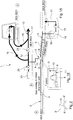
- the apparatus has a gas pipe 4 which is connected to the stem 10 and receives gas from the pipeline through the aperture.
- the stem 10 defines a path for gas between the inside of the pipeline 2 and the gas pipe 4.
- a flow of the multiphase fluid passes through the first portion 5, and enters the tee.
- Gas escapes naturally up through the stem of the tee into the gas pipe 4 (as “separated gas”), whilst liquid from the multiphase fluid remains inside the pipeline, passes the tee and enters into the second portion 6 of the pipeline (as “separated liquid”).
- gas is tapped off automatically, as the multiphase flow is passed along the pipeline as a result the gas and liquid contents are separated.
- the second portion of the pipeline may extend over a region of the seafloor with a slope in terrain.
- the natural changes in the seafloor topography may be utilised to provide the necessary slope of the pipeline, downstream of the tee.
- the pipe may lie on a sloping part of the seabed.
- the portion 6 may slope from the tee and follow along a slope of the seabed downwards into a topographic low region in the seabed.
- the tee may be arranged at a relative high point of the seabed.
- the pipeline may be arranged such that the second portion 6 has a slope greater than the first portion.
- the first portion 5 of the pipeline may be arranged horizontally.
- the tubular body section of the pipeline defined by the arms 8, 9 of the tee may be arranged horizontally, i.e. with a longitudinal through-axis in a horizontal plane.
- the tank and/or outlet may be arranged to let liquid out of the pump at a consistent rate over time, to the pump.
- the pump speed may be controllable to control the rate of liquid out of the tank. For example, the pump speed may be controlled or varied based on the level of liquid in the tank. From the pump, the liquid is driven out of the hole along a liquid transport pipe.
- the pump and tank may be located at the seabed for example in a topographic depression.
- the gradient of the slope of the second pipe portion 6 may provide sufficient height above the pump that a significant gravity component contributes to driving the liquid flow.
- the hole 21 may be provided with a receptacle or tubular lining to define the necessary space therein for receiving the tank 18 and pump 19.
- the hole is typically open to the sea.
- Other processing components may also be provided in the hole 21.
- the tee in this case is positioned a substantial distance away from the well, such that the pipeline portion 5 upstream of the tee acts to cool the fluid in the pipeline.
- the multiphase fluid from the well may at an upstream location close to the well head, have a temperature of around 60-120 degrees Celsius.
- the temperature of the seawater surrounding the pipeline at the seabed may be around 0 to 4 degrees.
- heat is transferred from the fluid across the wall of the pipeline to the surrounding sea causing the fluid inside the pipeline to cool.
- the fluid in the pipeline may have been cooled as a result of its transport through the pipe to a temperature of around 0 to 10 degrees Celsius.
- condensed liquid may be produced from the gas, contributing to reducing liquid content in the gas.
- the pipe tee may be arranged at least 5 km from the well.
- the pipeline portion 5 may have a length of at least 5km.
- a second pipeline and optionally further pipelines, could be provided in addition to pipeline 2 and arranged similarly.
- Such a second (or each further pipeline) may be provided with a tee through a wall of the second pipeline to separate gas from the liquid, and separated gas may be supplied to a compressor and be compressed. Multiple compressors may be used.
- the compressed gas from each such pipeline may be supplied into a single trunk line 12.
- the trunk line may then act as a common transport pipeline for transporting separated and compressed gas from the different pipelines.
- Separated liquid from each pipeline may be conveyed to a pump located in a single excavation, caisson or glory hole 21.
- the hole 21 may then act as a common hole housing equipment for processing liquid from the different pipelines.
- a pipe tee provides a simple way of tapping off gas from the pipeline to separate the gas and liquid without any other modification to the pipeline than providing an outlet in the wall of the pipe and connecting the gas pipe thereto. That is, the simple presence of an outlet through the wall in the upper portion of a pipe section removes the gas flowing adjacent to or against the wall inside the pipeline. There is minimal disturbance to the flow, such that the liquid may continue from pipe portion 5 into the pipe portion 6 as a stratified fluid.
- the flow path for fluid through the pipeline portions 5, 6 and the tee is a smooth, unobstructed and/or slowly changing flow path.
- the pipeline 2 can simply consist of basic standard pipeline sections and fittings. The walls of the pipeline and/or the tee, i.e. stem and arms, keep the surrounding sea out of the pipeline and/or tee. There is no need for any internal modification to the diameter or any arrangement to stimulate the fluid or liquid inside the pipe in proximity to the outlet aperture or tee.
Landscapes
- Geology (AREA)
- Life Sciences & Earth Sciences (AREA)
- Engineering & Computer Science (AREA)
- Mining & Mineral Resources (AREA)
- Environmental & Geological Engineering (AREA)
- Fluid Mechanics (AREA)
- Physics & Mathematics (AREA)
- General Life Sciences & Earth Sciences (AREA)
- Geochemistry & Mineralogy (AREA)
- Chemical & Material Sciences (AREA)
- Chemical Kinetics & Catalysis (AREA)
- Jet Pumps And Other Pumps (AREA)
- Structures Of Non-Positive Displacement Pumps (AREA)
- Earth Drilling (AREA)
Claims (9)
- Unterseevorrichtung zur Verarbeitung eines Fluids aus einem Bohrloch, wobei die Vorrichtung Folgendes umfasst:eine Rohrleitung (2), die dafür angeordnet ist, einen Strom des Fluids aufzunehmen, wobei das Fluid Flüssigkeit und Gas umfasst,einen Auslass (3), der sich durch eine Wand der Rohrleitung erstreckt, wobei der Auslass (3) dafür angeordnet ist, durch den Gas aus der Rohrleitung abzulassen, um das Gas von der Flüssigkeit zu trennen und abgetrenntes Gas und abgetrennte Flüssigkeit zu erzeugen, wobei die Rohrleitung angepasst ist, um das Fluid aus dem Bohrloch in einem Abschnitt der Rohrleitung, stromaufwärts von dem Auslass, durch Übertragen von Wärme von dem Fluid über die Wand der Rohrleitung zu der umgebenden See zu kühlen;einen Verdichter (14), der dafür angeordnet ist, Gas von dem Auslass (3) aufzunehmen, und dafür angeordnet ist, das abgetrennte Gas zu verdichten;einen Tank (18), in dem ein Abschnitt (6) der Rohrleitung, stromabwärts von dem Auslass, dafür angeordnet ist, die abgetrennte Flüssigkeit aufzunehmen, und wobei der Abschnitt (6) der Rohrleitung über wenigstens einen Teil seiner Länge abgeschrägt ist, wobei der Abschnitt (6) von dem Auslass nach unten zu dem Tank (18) hin schräg ist, wobei der Tank dafür angeordnet ist, Fluid aus dem Abschnitt (6) der Rohrleitung aufzunehmen, wobei der Tank unterhalb des Auslasses angeordnet ist und wobei, bei Anwendung, die Flüssigkeit in dem Tank ein totes Ende für das Gas bereitstellt, so dass sich das Gas gegen den Strom von Flüssigkeit zu dem Auslass nach oben bewegt;eine Pumpe (19), die dafür angeordnet ist, abgetrennte Flüssigkeit aus dem Tank aufzunehmen und die abgetrennte Flüssigkeit zu pumpen, um die Flüssigkeit zu einer Anlage zu bewegen, die stromabwärts von der Pumpe angeordnet ist, wobei der Tank stromaufwärts von der Pumpe angeordnet ist.
- Unterseevorrichtung nach Anspruch 1, wobei die Rohrleitung ein T-Rohr (3) aufweist, das den Auslass definiert.
- Unterseevorrichtung nach Anspruch 2, wobei das T-Rohr einen Schaft (10) und einen ersten (8) und einen zweiten (9) Arm, die mit dem Schaft verbunden sind und sich von demselben aus erstrecken, aufweist, wobei die Arme eine röhrenförmige Sektion der Rohrleitung definieren und der Schaft den Auslass für das Gas definiert.
- Unterseevorrichtung nach Anspruch 3,
wobei der Schaft (10) im Wesentlichen senkrecht zu den Armen ist, um ein T-förmiges T-Rohr zu definieren, oder wobei der Schaft in Bezug auf wenigstens einen von dem ersten (8) und dem zweiten (9) Arm nicht senkrecht ist und im Allgemeinen Y-förmig ist, und
wobei das T-Rohr so angeordnet ist, dass sich der Schaft bei Anwendung im Wesentlichen vertikal erstreckt. - Unterseevorrichtung nach Anspruch 1, wobei die Pumpe und/oder der Tank dafür angeordnet ist/sind, in einer Struktur positioniert zu werden, die an dem Meeresboden gebildet ist, wobei sie ein Loch umfasst, das sich von dem Meeresboden in den Untergrund erstreckt.
- Unterseevorrichtung nach Anspruch 1, die ferner ein Seegerüst umfasst, das dafür angeordnet ist, auf dem Meeresboden positioniert zu werden, um den Verdichter (14) zu tragen, dafür angeordnet, die abgetrennte Flüssigkeit entlang einer Route, die nicht durch das Gerüst zum Tragen des Verdichters hindurchgeht, zu befördern.
- Unterseevorrichtung nach einem der vorhergehenden Ansprüche, wobei der Verdichter (14) dafür angeordnet ist, verdichtetes Gas in eine Transportrohrleitung zum Transportieren des verdichteten Gases zu der stromabwärts angeordneten Anlage abzugeben, wobei die Transportrohrleitung einen Innendurchmesser in dem Bereich von rund 40 bis 50 Zoll, 1,02 bis 1,27 Meter, aufweist.
- Verfahren zur Unterseeverarbeitung eines Fluids aus einem Bohrloch, wobei das Verfahren die folgenden Schritte umfasst:a. Bereitstellen einer Rohrleitung (2) unter Wasser, wobei die Rohrleitung einen Auslass (3) durch eine Wand aufweist, Kühlen des Fluids in einer Sektion der Rohrleitung, stromaufwärts von dem Auslass, durch Übertragen von Wärme von der Flüssigkeit über die Wand der Rohrleitung zu der umgebenden See; wobei ein Abschnitt (6) der Rohrleitung, stromabwärts von dem Auslass, dafür angeordnet ist, abgetrennte Flüssigkeit aufzunehmen, und wobei der Abschnitt (6) der Rohrleitung über wenigstens einen Teil seiner Länge abgeschrägt ist, wobei der Abschnitt (6) von dem Auslass nach unten zu einem Tank (18) hin schräg ist, wobei eine Pumpe (19) stromabwärts von dem Tank bereitgestellt wird, wobei die Rohrleitung am oder auf dem Meeresboden angeordnet ist und die abgeschrägten Abschnitte in einer Richtung stromabwärts zwischen einem ersten Punkt entlang der Rohrleitung und einem zweiten Punkt entlang der Rohrleitung schräg sind, und der Meeresboden an dem zweiten Punkt niedriger ist als an dem ersten Punkt; und wobei an dem zweiten Punkt eine topographische Vertiefung an dem Meeresboden vorhanden ist, Bereitstellen des Tanks innerhalb der topographischen Vertiefung,b. Aufnehmen eines Stroms des Fluids innerhalb der Rohrleitung,c. Ablassen von Gas aus der Rohrleitung durch den Auslass, um das Gas von der Flüssigkeit zu trennen, um abgetrenntes Gas und abgetrennte Flüssigkeit zu erzeugen, Zulassen, dass sich Gas gegen den Strom von Flüssigkeit zu dem Auslass durch den Abschnitt (6) der Rohrleitung nach oben bewegt; undd. Verdichten des abgetrennten Gases,e. Aufnehmen von abgetrennter Flüssigkeit in dem Tank (18),f. Pumpen der abgetrennten Flüssigkeit, um die Flüssigkeit zu einer Anlage zu bewegen, die stromabwärts von der Pumpe angeordnet ist.
- Verfahren nach Anspruch 8 unter Verwendung der Vorrichtung nach einem der Ansprüche 1 bis 7.
Applications Claiming Priority (2)
| Application Number | Priority Date | Filing Date | Title |
|---|---|---|---|
| GB1213953.1A GB2504695B (en) | 2012-08-06 | 2012-08-06 | Subsea processing |
| PCT/EP2013/066503 WO2014023743A2 (en) | 2012-08-06 | 2013-08-06 | Subsea processing |
Publications (2)
| Publication Number | Publication Date |
|---|---|
| EP2895247A2 EP2895247A2 (de) | 2015-07-22 |
| EP2895247B1 true EP2895247B1 (de) | 2019-12-25 |
Family
ID=46934911
Family Applications (1)
| Application Number | Title | Priority Date | Filing Date |
|---|---|---|---|
| EP13747831.9A Active EP2895247B1 (de) | 2012-08-06 | 2013-08-06 | Unterseeverarbeitung |
Country Status (10)
| Country | Link |
|---|---|
| US (1) | US9790778B2 (de) |
| EP (1) | EP2895247B1 (de) |
| AU (1) | AU2013301553B2 (de) |
| BR (1) | BR112015002575B1 (de) |
| CA (1) | CA2881066C (de) |
| GB (1) | GB2504695B (de) |
| MX (1) | MX357053B (de) |
| NZ (1) | NZ705596A (de) |
| RU (1) | RU2643965C2 (de) |
| WO (1) | WO2014023743A2 (de) |
Families Citing this family (4)
| Publication number | Priority date | Publication date | Assignee | Title |
|---|---|---|---|---|
| GB2522863A (en) * | 2014-02-05 | 2015-08-12 | Statoil Petroleum As | Subsea processing |
| US10583373B2 (en) * | 2016-12-06 | 2020-03-10 | Fluidsep As | Method and device for separation of liquids and gas with use of inclined and rounded holes or channels in the wall of a pipe |
| CN106938152B (zh) * | 2017-03-29 | 2018-10-16 | 青岛理工大学 | 倾斜管式水下预脱水脱气分离装置 |
| CN117127945B (zh) * | 2023-09-19 | 2024-01-30 | 青岛海洋地质研究所 | 海洋天然气水合物高效收集装置及收集方法 |
Family Cites Families (26)
| Publication number | Priority date | Publication date | Assignee | Title |
|---|---|---|---|---|
| US4147454A (en) * | 1975-10-23 | 1979-04-03 | Nor-Am Resources Technology Incorporated | Method of and apparatus for construction of pipes for marine use, as for ocean mining and the like |
| AU592748B2 (en) * | 1984-05-22 | 1990-01-25 | John B Lincoln | Pipeline jetting/mechanical trenching sled |
| DE3810951A1 (de) * | 1988-03-31 | 1989-10-12 | Klein Schanzlin & Becker Ag | Verfahren und vorrichtung zur energiegewinnung aus oelquellen |
| US5505502A (en) * | 1993-06-09 | 1996-04-09 | Shell Oil Company | Multiple-seal underwater pipe-riser connector |
| GB9512513D0 (en) * | 1995-06-20 | 1995-08-23 | Guest John D | Improvements in or relating to T-connectors |
| FR2748293B1 (fr) * | 1996-05-03 | 1998-06-19 | Coflexip | Installation d'exploitation petroliere incorporant des socles de support de manifold, socle et procede de pose |
| GB2317222B (en) | 1996-09-04 | 1998-11-25 | Babcock & Wilcox Co | Heat pipe heat exchangers for subsea pipelines |
| US6502635B1 (en) * | 2001-06-20 | 2003-01-07 | Chevron U.S.A. Inc. | Sub-sea membrane separation system with temperature control |
| NO321342B1 (no) * | 2001-07-20 | 2006-05-02 | Vetco Aibel As | Anordning ved rorledningsavboyning |
| NO316840B1 (no) * | 2002-08-16 | 2004-05-24 | Norsk Hydro As | Rorseparator for separasjon av fluid, spesielt olje, gass og vann |
| DE10310002B3 (de) * | 2003-02-27 | 2004-09-16 | Deutsches Zentrum für Luft- und Raumfahrt e.V. | Trennverfahren und Trennvorrichtung für Flüssigkeit und Gas in einem Zwei-Phasen-Gemisch |
| NO321304B1 (no) * | 2003-09-12 | 2006-04-24 | Kvaerner Oilfield Prod As | Undervanns kompressorstasjon |
| WO2006010765A1 (en) | 2004-07-27 | 2006-02-02 | Shell Internationale Research Maatschappij B.V. | Plant for separating a mixture of oil, water and gas |
| US7963721B2 (en) * | 2004-09-21 | 2011-06-21 | Kellogg Brown & Root Llc | Distributed buoyancy subsea pipeline apparatus and method |
| US7025533B1 (en) * | 2004-09-21 | 2006-04-11 | Kellogg Brown & Root, Inc. | Concentrated buoyancy subsea pipeline apparatus and method |
| WO2006058000A1 (en) * | 2004-11-24 | 2006-06-01 | Shell Internationale Research Maatschappij B.V. | Separator for multi-phase slug flow and method of designing same |
| NO329480B1 (no) * | 2005-03-16 | 2010-10-25 | Norsk Hydro As | Anordning ved en rorseparator |
| US20090297271A1 (en) * | 2005-03-17 | 2009-12-03 | Hummert George T | Turf Playing Surface Aeration and Drainage System |
| US7464734B2 (en) * | 2005-08-08 | 2008-12-16 | Xuejie Liu | Self-cooling pipeline system and method for transfer of cryogenic fluids |
| RU2412738C2 (ru) * | 2005-12-21 | 2011-02-27 | Шелл Интернэшнл Рисерч Маатсхаппий Б.В. | Система и способ разделения потока флюида |
| DE102006002242A1 (de) * | 2006-01-17 | 2007-07-19 | Linde Ag | Slugcatcher |
| US8066077B2 (en) * | 2007-12-17 | 2011-11-29 | Baker Hughes Incorporated | Electrical submersible pump and gas compressor |
| NO332062B1 (no) * | 2008-02-28 | 2012-06-11 | Statoilhydro Asa | Sammenstilling for separasjon av en flerfasestrom |
| CN201415071Y (zh) * | 2009-06-18 | 2010-03-03 | 中芯国际集成电路制造(上海)有限公司 | 用于气液分离的管路组件 |
| FR2952671B1 (fr) * | 2009-11-17 | 2011-12-09 | Saipem Sa | Installation de liaisons fond-surface disposees en eventail |
| US9359878B2 (en) * | 2014-03-12 | 2016-06-07 | Exxonmobil Upstream Research Company | Split flow pipe separator |
-
2012
- 2012-08-06 GB GB1213953.1A patent/GB2504695B/en active Active
-
2013
- 2013-08-06 WO PCT/EP2013/066503 patent/WO2014023743A2/en not_active Ceased
- 2013-08-06 MX MX2015001743A patent/MX357053B/es active IP Right Grant
- 2013-08-06 BR BR112015002575-7A patent/BR112015002575B1/pt active IP Right Grant
- 2013-08-06 RU RU2015106440A patent/RU2643965C2/ru active
- 2013-08-06 CA CA2881066A patent/CA2881066C/en active Active
- 2013-08-06 US US14/419,867 patent/US9790778B2/en active Active
- 2013-08-06 NZ NZ705596A patent/NZ705596A/en not_active IP Right Cessation
- 2013-08-06 AU AU2013301553A patent/AU2013301553B2/en active Active
- 2013-08-06 EP EP13747831.9A patent/EP2895247B1/de active Active
Non-Patent Citations (1)
| Title |
|---|
| None * |
Also Published As
| Publication number | Publication date |
|---|---|
| WO2014023743A3 (en) | 2014-10-30 |
| WO2014023743A2 (en) | 2014-02-13 |
| US9790778B2 (en) | 2017-10-17 |
| MX2015001743A (es) | 2015-10-09 |
| BR112015002575A2 (pt) | 2018-05-22 |
| CA2881066C (en) | 2021-03-23 |
| CA2881066A1 (en) | 2014-02-13 |
| MX357053B (es) | 2018-06-25 |
| RU2015106440A (ru) | 2016-09-27 |
| BR112015002575B1 (pt) | 2021-09-28 |
| GB2504695A (en) | 2014-02-12 |
| AU2013301553A1 (en) | 2015-03-05 |
| BR112015002575A8 (pt) | 2021-08-17 |
| US20150204180A1 (en) | 2015-07-23 |
| RU2643965C2 (ru) | 2018-02-06 |
| EP2895247A2 (de) | 2015-07-22 |
| GB2504695B (en) | 2018-05-30 |
| NZ705596A (en) | 2017-04-28 |
| AU2013301553B2 (en) | 2018-01-18 |
| GB201213953D0 (en) | 2012-09-19 |
Similar Documents
| Publication | Publication Date | Title |
|---|---|---|
| RU2448245C1 (ru) | Сепарирование и улавливание жидкостей мультифазного потока | |
| CA3008372C (en) | Submerged hydrocarbon recovery apparatus | |
| RU2462591C2 (ru) | Подводная установка и способ для разделения жидкой фракции и газовой фракции | |
| US20160348490A1 (en) | Subsea processing | |
| US20250215773A1 (en) | Drain Apparatus for a Subsea Pipeline | |
| US11577180B2 (en) | Subsea processing of crude oil | |
| BRPI0714011A2 (pt) | sistema para produção de petróleo e fração de gás mais pesada de uma reservatório sob o leito do mar, método para produção de petróleo e frações de gás mais pesadas de um reservatório sob o leito do mar, e, embarcação | |
| EP2895247B1 (de) | Unterseeverarbeitung | |
| US11598193B2 (en) | Subsea processing of crude oil | |
| CN102428244B (zh) | 保护柔性立管的方法及其设备 | |
| WO2005040670A1 (en) | Method and system for reducing liquid accumulation in a multiphase flow pipeline | |
| GB2554076A (en) | Subsea hydrocarbon processing | |
| BR112019019329B1 (pt) | Unidade de produção submarina para tratamento submarino de óleo e método de separação de fluidos de uma corrente de poço contendo óleo de multifase | |
| OA19026A (en) | A drain apparatus for a subsea pipeline | |
| NZ791631A (en) | A drain apparatus for a subsea pipeline |
Legal Events
| Date | Code | Title | Description |
|---|---|---|---|
| PUAI | Public reference made under article 153(3) epc to a published international application that has entered the european phase |
Free format text: ORIGINAL CODE: 0009012 |
|
| 17P | Request for examination filed |
Effective date: 20150218 |
|
| AK | Designated contracting states |
Kind code of ref document: A2 Designated state(s): AL AT BE BG CH CY CZ DE DK EE ES FI FR GB GR HR HU IE IS IT LI LT LU LV MC MK MT NL NO PL PT RO RS SE SI SK SM TR |
|
| AX | Request for extension of the european patent |
Extension state: BA ME |
|
| DAX | Request for extension of the european patent (deleted) | ||
| STAA | Information on the status of an ep patent application or granted ep patent |
Free format text: STATUS: EXAMINATION IS IN PROGRESS |
|
| 17Q | First examination report despatched |
Effective date: 20170328 |
|
| RAP1 | Party data changed (applicant data changed or rights of an application transferred) |
Owner name: EQUINOR ENERGY AS |
|
| GRAP | Despatch of communication of intention to grant a patent |
Free format text: ORIGINAL CODE: EPIDOSNIGR1 |
|
| STAA | Information on the status of an ep patent application or granted ep patent |
Free format text: STATUS: GRANT OF PATENT IS INTENDED |
|
| INTG | Intention to grant announced |
Effective date: 20190703 |
|
| GRAS | Grant fee paid |
Free format text: ORIGINAL CODE: EPIDOSNIGR3 |
|
| GRAA | (expected) grant |
Free format text: ORIGINAL CODE: 0009210 |
|
| STAA | Information on the status of an ep patent application or granted ep patent |
Free format text: STATUS: THE PATENT HAS BEEN GRANTED |
|
| RBV | Designated contracting states (corrected) |
Designated state(s): AL AT BE BG CH CY CZ DE DK EE ES FI FR GR HR HU IE IS IT LI LT LU LV MC MK MT NL NO PL PT RO RS SE SI SK SM TR |
|
| RIN1 | Information on inventor provided before grant (corrected) |
Inventor name: GUNNEROED, TOR ARNE Inventor name: BAKKE, WILLIAM Inventor name: HOLM, HENNING |
|
| AK | Designated contracting states |
Kind code of ref document: B1 Designated state(s): AL AT BE BG CH CY CZ DE DK EE ES FI FR GR HR HU IE IS IT LI LT LU LV MC MK MT NL NO PL PT RO RS SE SI SK SM TR |
|
| REG | Reference to a national code |
Ref country code: CH Ref legal event code: EP |
|
| REG | Reference to a national code |
Ref country code: DE Ref legal event code: R096 Ref document number: 602013064354 Country of ref document: DE |
|
| REG | Reference to a national code |
Ref country code: AT Ref legal event code: REF Ref document number: 1216531 Country of ref document: AT Kind code of ref document: T Effective date: 20200115 |
|
| REG | Reference to a national code |
Ref country code: IE Ref legal event code: FG4D |
|
| REG | Reference to a national code |
Ref country code: NO Ref legal event code: T2 Effective date: 20191225 |
|
| REG | Reference to a national code |
Ref country code: NL Ref legal event code: MP Effective date: 20191225 |
|
| PG25 | Lapsed in a contracting state [announced via postgrant information from national office to epo] |
Ref country code: LV Free format text: LAPSE BECAUSE OF FAILURE TO SUBMIT A TRANSLATION OF THE DESCRIPTION OR TO PAY THE FEE WITHIN THE PRESCRIBED TIME-LIMIT Effective date: 20191225 Ref country code: SE Free format text: LAPSE BECAUSE OF FAILURE TO SUBMIT A TRANSLATION OF THE DESCRIPTION OR TO PAY THE FEE WITHIN THE PRESCRIBED TIME-LIMIT Effective date: 20191225 Ref country code: BG Free format text: LAPSE BECAUSE OF FAILURE TO SUBMIT A TRANSLATION OF THE DESCRIPTION OR TO PAY THE FEE WITHIN THE PRESCRIBED TIME-LIMIT Effective date: 20200325 Ref country code: FI Free format text: LAPSE BECAUSE OF FAILURE TO SUBMIT A TRANSLATION OF THE DESCRIPTION OR TO PAY THE FEE WITHIN THE PRESCRIBED TIME-LIMIT Effective date: 20191225 Ref country code: LT Free format text: LAPSE BECAUSE OF FAILURE TO SUBMIT A TRANSLATION OF THE DESCRIPTION OR TO PAY THE FEE WITHIN THE PRESCRIBED TIME-LIMIT Effective date: 20191225 Ref country code: GR Free format text: LAPSE BECAUSE OF FAILURE TO SUBMIT A TRANSLATION OF THE DESCRIPTION OR TO PAY THE FEE WITHIN THE PRESCRIBED TIME-LIMIT Effective date: 20200326 |
|
| REG | Reference to a national code |
Ref country code: LT Ref legal event code: MG4D |
|
| PG25 | Lapsed in a contracting state [announced via postgrant information from national office to epo] |
Ref country code: RS Free format text: LAPSE BECAUSE OF FAILURE TO SUBMIT A TRANSLATION OF THE DESCRIPTION OR TO PAY THE FEE WITHIN THE PRESCRIBED TIME-LIMIT Effective date: 20191225 Ref country code: HR Free format text: LAPSE BECAUSE OF FAILURE TO SUBMIT A TRANSLATION OF THE DESCRIPTION OR TO PAY THE FEE WITHIN THE PRESCRIBED TIME-LIMIT Effective date: 20191225 |
|
| PG25 | Lapsed in a contracting state [announced via postgrant information from national office to epo] |
Ref country code: AL Free format text: LAPSE BECAUSE OF FAILURE TO SUBMIT A TRANSLATION OF THE DESCRIPTION OR TO PAY THE FEE WITHIN THE PRESCRIBED TIME-LIMIT Effective date: 20191225 |
|
| PG25 | Lapsed in a contracting state [announced via postgrant information from national office to epo] |
Ref country code: RO Free format text: LAPSE BECAUSE OF FAILURE TO SUBMIT A TRANSLATION OF THE DESCRIPTION OR TO PAY THE FEE WITHIN THE PRESCRIBED TIME-LIMIT Effective date: 20191225 Ref country code: CZ Free format text: LAPSE BECAUSE OF FAILURE TO SUBMIT A TRANSLATION OF THE DESCRIPTION OR TO PAY THE FEE WITHIN THE PRESCRIBED TIME-LIMIT Effective date: 20191225 Ref country code: PT Free format text: LAPSE BECAUSE OF FAILURE TO SUBMIT A TRANSLATION OF THE DESCRIPTION OR TO PAY THE FEE WITHIN THE PRESCRIBED TIME-LIMIT Effective date: 20200520 Ref country code: NL Free format text: LAPSE BECAUSE OF FAILURE TO SUBMIT A TRANSLATION OF THE DESCRIPTION OR TO PAY THE FEE WITHIN THE PRESCRIBED TIME-LIMIT Effective date: 20191225 Ref country code: EE Free format text: LAPSE BECAUSE OF FAILURE TO SUBMIT A TRANSLATION OF THE DESCRIPTION OR TO PAY THE FEE WITHIN THE PRESCRIBED TIME-LIMIT Effective date: 20191225 |
|
| PG25 | Lapsed in a contracting state [announced via postgrant information from national office to epo] |
Ref country code: SK Free format text: LAPSE BECAUSE OF FAILURE TO SUBMIT A TRANSLATION OF THE DESCRIPTION OR TO PAY THE FEE WITHIN THE PRESCRIBED TIME-LIMIT Effective date: 20191225 Ref country code: IS Free format text: LAPSE BECAUSE OF FAILURE TO SUBMIT A TRANSLATION OF THE DESCRIPTION OR TO PAY THE FEE WITHIN THE PRESCRIBED TIME-LIMIT Effective date: 20200425 Ref country code: SM Free format text: LAPSE BECAUSE OF FAILURE TO SUBMIT A TRANSLATION OF THE DESCRIPTION OR TO PAY THE FEE WITHIN THE PRESCRIBED TIME-LIMIT Effective date: 20191225 |
|
| REG | Reference to a national code |
Ref country code: DE Ref legal event code: R097 Ref document number: 602013064354 Country of ref document: DE |
|
| PG25 | Lapsed in a contracting state [announced via postgrant information from national office to epo] |
Ref country code: ES Free format text: LAPSE BECAUSE OF FAILURE TO SUBMIT A TRANSLATION OF THE DESCRIPTION OR TO PAY THE FEE WITHIN THE PRESCRIBED TIME-LIMIT Effective date: 20191225 Ref country code: DK Free format text: LAPSE BECAUSE OF FAILURE TO SUBMIT A TRANSLATION OF THE DESCRIPTION OR TO PAY THE FEE WITHIN THE PRESCRIBED TIME-LIMIT Effective date: 20191225 |
|
| PLBE | No opposition filed within time limit |
Free format text: ORIGINAL CODE: 0009261 |
|
| STAA | Information on the status of an ep patent application or granted ep patent |
Free format text: STATUS: NO OPPOSITION FILED WITHIN TIME LIMIT |
|
| REG | Reference to a national code |
Ref country code: AT Ref legal event code: MK05 Ref document number: 1216531 Country of ref document: AT Kind code of ref document: T Effective date: 20191225 |
|
| PG25 | Lapsed in a contracting state [announced via postgrant information from national office to epo] |
Ref country code: SI Free format text: LAPSE BECAUSE OF FAILURE TO SUBMIT A TRANSLATION OF THE DESCRIPTION OR TO PAY THE FEE WITHIN THE PRESCRIBED TIME-LIMIT Effective date: 20191225 |
|
| 26N | No opposition filed |
Effective date: 20200928 |
|
| PG25 | Lapsed in a contracting state [announced via postgrant information from national office to epo] |
Ref country code: IT Free format text: LAPSE BECAUSE OF FAILURE TO SUBMIT A TRANSLATION OF THE DESCRIPTION OR TO PAY THE FEE WITHIN THE PRESCRIBED TIME-LIMIT Effective date: 20191225 Ref country code: AT Free format text: LAPSE BECAUSE OF FAILURE TO SUBMIT A TRANSLATION OF THE DESCRIPTION OR TO PAY THE FEE WITHIN THE PRESCRIBED TIME-LIMIT Effective date: 20191225 |
|
| PG25 | Lapsed in a contracting state [announced via postgrant information from national office to epo] |
Ref country code: PL Free format text: LAPSE BECAUSE OF FAILURE TO SUBMIT A TRANSLATION OF THE DESCRIPTION OR TO PAY THE FEE WITHIN THE PRESCRIBED TIME-LIMIT Effective date: 20191225 |
|
| REG | Reference to a national code |
Ref country code: DE Ref legal event code: R119 Ref document number: 602013064354 Country of ref document: DE |
|
| PG25 | Lapsed in a contracting state [announced via postgrant information from national office to epo] |
Ref country code: MC Free format text: LAPSE BECAUSE OF FAILURE TO SUBMIT A TRANSLATION OF THE DESCRIPTION OR TO PAY THE FEE WITHIN THE PRESCRIBED TIME-LIMIT Effective date: 20191225 |
|
| REG | Reference to a national code |
Ref country code: CH Ref legal event code: PL |
|
| PG25 | Lapsed in a contracting state [announced via postgrant information from national office to epo] |
Ref country code: LU Free format text: LAPSE BECAUSE OF NON-PAYMENT OF DUE FEES Effective date: 20200806 Ref country code: CH Free format text: LAPSE BECAUSE OF NON-PAYMENT OF DUE FEES Effective date: 20200831 Ref country code: LI Free format text: LAPSE BECAUSE OF NON-PAYMENT OF DUE FEES Effective date: 20200831 |
|
| REG | Reference to a national code |
Ref country code: BE Ref legal event code: MM Effective date: 20200831 |
|
| PG25 | Lapsed in a contracting state [announced via postgrant information from national office to epo] |
Ref country code: FR Free format text: LAPSE BECAUSE OF NON-PAYMENT OF DUE FEES Effective date: 20200831 Ref country code: DE Free format text: LAPSE BECAUSE OF NON-PAYMENT OF DUE FEES Effective date: 20210302 |
|
| PG25 | Lapsed in a contracting state [announced via postgrant information from national office to epo] |
Ref country code: BE Free format text: LAPSE BECAUSE OF NON-PAYMENT OF DUE FEES Effective date: 20200831 Ref country code: IE Free format text: LAPSE BECAUSE OF NON-PAYMENT OF DUE FEES Effective date: 20200806 |
|
| PG25 | Lapsed in a contracting state [announced via postgrant information from national office to epo] |
Ref country code: TR Free format text: LAPSE BECAUSE OF FAILURE TO SUBMIT A TRANSLATION OF THE DESCRIPTION OR TO PAY THE FEE WITHIN THE PRESCRIBED TIME-LIMIT Effective date: 20191225 Ref country code: MT Free format text: LAPSE BECAUSE OF FAILURE TO SUBMIT A TRANSLATION OF THE DESCRIPTION OR TO PAY THE FEE WITHIN THE PRESCRIBED TIME-LIMIT Effective date: 20191225 Ref country code: CY Free format text: LAPSE BECAUSE OF FAILURE TO SUBMIT A TRANSLATION OF THE DESCRIPTION OR TO PAY THE FEE WITHIN THE PRESCRIBED TIME-LIMIT Effective date: 20191225 |
|
| PG25 | Lapsed in a contracting state [announced via postgrant information from national office to epo] |
Ref country code: MK Free format text: LAPSE BECAUSE OF FAILURE TO SUBMIT A TRANSLATION OF THE DESCRIPTION OR TO PAY THE FEE WITHIN THE PRESCRIBED TIME-LIMIT Effective date: 20191225 |
|
| P01 | Opt-out of the competence of the unified patent court (upc) registered |
Effective date: 20230525 |
|
| PGFP | Annual fee paid to national office [announced via postgrant information from national office to epo] |
Ref country code: NO Payment date: 20250819 Year of fee payment: 13 |