EP2895221B1 - Medizinische injektionsvorrichtung - Google Patents
Medizinische injektionsvorrichtung Download PDFInfo
- Publication number
- EP2895221B1 EP2895221B1 EP13759994.0A EP13759994A EP2895221B1 EP 2895221 B1 EP2895221 B1 EP 2895221B1 EP 13759994 A EP13759994 A EP 13759994A EP 2895221 B1 EP2895221 B1 EP 2895221B1
- Authority
- EP
- European Patent Office
- Prior art keywords
- switching state
- nanoparticles
- polymer
- injection device
- matrix polymer
- Prior art date
- Legal status (The legal status is an assumption and is not a legal conclusion. Google has not performed a legal analysis and makes no representation as to the accuracy of the status listed.)
- Not-in-force
Links
- 238000010999 medical injection Methods 0.000 title claims description 54
- 239000002114 nanocomposite Substances 0.000 claims description 188
- 229920000642 polymer Polymers 0.000 claims description 150
- 229920002451 polyvinyl alcohol Polymers 0.000 claims description 134
- 239000011159 matrix material Substances 0.000 claims description 94
- 239000002105 nanoparticle Substances 0.000 claims description 83
- 239000000463 material Substances 0.000 claims description 72
- 238000003860 storage Methods 0.000 claims description 59
- 229920002678 cellulose Polymers 0.000 claims description 42
- 239000001913 cellulose Substances 0.000 claims description 41
- 235000010980 cellulose Nutrition 0.000 claims description 41
- XLYOFNOQVPJJNP-UHFFFAOYSA-N water Substances O XLYOFNOQVPJJNP-UHFFFAOYSA-N 0.000 claims description 34
- 230000003993 interaction Effects 0.000 claims description 33
- 241000251555 Tunicata Species 0.000 claims description 25
- 238000000034 method Methods 0.000 claims description 23
- 239000000203 mixture Substances 0.000 claims description 23
- 239000002121 nanofiber Substances 0.000 claims description 20
- 229920000742 Cotton Polymers 0.000 claims description 18
- 238000001035 drying Methods 0.000 claims description 18
- -1 poly(acrylic acid) Polymers 0.000 claims description 18
- 238000010438 heat treatment Methods 0.000 claims description 17
- 229910052739 hydrogen Inorganic materials 0.000 claims description 14
- 239000001257 hydrogen Substances 0.000 claims description 14
- 230000008859 change Effects 0.000 claims description 12
- 238000000748 compression moulding Methods 0.000 claims description 12
- 230000015572 biosynthetic process Effects 0.000 claims description 10
- 239000004372 Polyvinyl alcohol Substances 0.000 claims description 8
- 230000001747 exhibiting effect Effects 0.000 claims description 8
- 230000008569 process Effects 0.000 claims description 8
- 238000004519 manufacturing process Methods 0.000 claims description 5
- 230000001939 inductive effect Effects 0.000 claims description 4
- 239000004952 Polyamide Substances 0.000 claims description 3
- 229920001577 copolymer Polymers 0.000 claims description 3
- 239000000178 monomer Substances 0.000 claims description 3
- 229920002647 polyamide Polymers 0.000 claims description 3
- 229920002101 Chitin Polymers 0.000 claims description 2
- 229920001661 Chitosan Polymers 0.000 claims description 2
- 229920002125 Sokalan® Polymers 0.000 claims description 2
- 229920002472 Starch Polymers 0.000 claims description 2
- 229920000615 alginic acid Polymers 0.000 claims description 2
- 235000010443 alginic acid Nutrition 0.000 claims description 2
- 150000004676 glycans Chemical class 0.000 claims description 2
- 229920001277 pectin Polymers 0.000 claims description 2
- 239000001814 pectin Substances 0.000 claims description 2
- 235000010987 pectin Nutrition 0.000 claims description 2
- 229920002401 polyacrylamide Polymers 0.000 claims description 2
- 229920000728 polyester Polymers 0.000 claims description 2
- 229920001282 polysaccharide Polymers 0.000 claims description 2
- 239000005017 polysaccharide Substances 0.000 claims description 2
- 102000004169 proteins and genes Human genes 0.000 claims description 2
- 108090000623 proteins and genes Proteins 0.000 claims description 2
- 239000008107 starch Substances 0.000 claims description 2
- 235000019698 starch Nutrition 0.000 claims description 2
- 229920002554 vinyl polymer Polymers 0.000 claims description 2
- 239000007788 liquid Substances 0.000 claims 1
- 229920002717 polyvinylpyridine Polymers 0.000 claims 1
- 230000008961 swelling Effects 0.000 description 30
- 239000006185 dispersion Substances 0.000 description 18
- 229920002689 polyvinyl acetate Polymers 0.000 description 13
- 239000011118 polyvinyl acetate Substances 0.000 description 13
- 238000012545 processing Methods 0.000 description 13
- QAOWNCQODCNURD-UHFFFAOYSA-N Sulfuric acid Chemical compound OS(O)(=O)=O QAOWNCQODCNURD-UHFFFAOYSA-N 0.000 description 12
- 239000000523 sample Substances 0.000 description 12
- 239000008367 deionised water Substances 0.000 description 9
- 229910021641 deionized water Inorganic materials 0.000 description 9
- 230000000694 effects Effects 0.000 description 9
- 239000012530 fluid Substances 0.000 description 9
- 238000005259 measurement Methods 0.000 description 9
- 230000002829 reductive effect Effects 0.000 description 9
- 210000001724 microfibril Anatomy 0.000 description 8
- 210000001519 tissue Anatomy 0.000 description 8
- 230000003044 adaptive effect Effects 0.000 description 7
- 210000001175 cerebrospinal fluid Anatomy 0.000 description 7
- 238000000113 differential scanning calorimetry Methods 0.000 description 7
- 238000002955 isolation Methods 0.000 description 7
- 230000004962 physiological condition Effects 0.000 description 7
- 229920001046 Nanocellulose Polymers 0.000 description 6
- 239000002253 acid Substances 0.000 description 6
- 238000004458 analytical method Methods 0.000 description 6
- 238000002474 experimental method Methods 0.000 description 6
- 230000007062 hydrolysis Effects 0.000 description 6
- 238000006460 hydrolysis reaction Methods 0.000 description 6
- 238000007654 immersion Methods 0.000 description 6
- 230000001965 increasing effect Effects 0.000 description 6
- 238000002347 injection Methods 0.000 description 6
- 239000007924 injection Substances 0.000 description 6
- 238000003780 insertion Methods 0.000 description 6
- 238000002844 melting Methods 0.000 description 6
- 230000008018 melting Effects 0.000 description 6
- 238000005325 percolation Methods 0.000 description 6
- 230000007704 transition Effects 0.000 description 6
- 238000005903 acid hydrolysis reaction Methods 0.000 description 5
- 238000004630 atomic force microscopy Methods 0.000 description 5
- 210000001124 body fluid Anatomy 0.000 description 5
- 239000010839 body fluid Substances 0.000 description 5
- 238000000402 conductometric titration Methods 0.000 description 5
- 239000000470 constituent Substances 0.000 description 5
- 230000037431 insertion Effects 0.000 description 5
- 235000019422 polyvinyl alcohol Nutrition 0.000 description 5
- 230000002787 reinforcement Effects 0.000 description 5
- 230000002441 reversible effect Effects 0.000 description 5
- 238000000527 sonication Methods 0.000 description 5
- 238000003756 stirring Methods 0.000 description 5
- 238000004627 transmission electron microscopy Methods 0.000 description 5
- 230000003014 reinforcing effect Effects 0.000 description 4
- 238000004626 scanning electron microscopy Methods 0.000 description 4
- 238000012360 testing method Methods 0.000 description 4
- 238000011282 treatment Methods 0.000 description 4
- 241001631457 Cannula Species 0.000 description 3
- VEXZGXHMUGYJMC-UHFFFAOYSA-N Hydrochloric acid Chemical compound Cl VEXZGXHMUGYJMC-UHFFFAOYSA-N 0.000 description 3
- HEMHJVSKTPXQMS-UHFFFAOYSA-M Sodium hydroxide Chemical compound [OH-].[Na+] HEMHJVSKTPXQMS-UHFFFAOYSA-M 0.000 description 3
- 229910000831 Steel Inorganic materials 0.000 description 3
- 230000008901 benefit Effects 0.000 description 3
- 229910052799 carbon Inorganic materials 0.000 description 3
- 230000000875 corresponding effect Effects 0.000 description 3
- 230000003247 decreasing effect Effects 0.000 description 3
- 230000001419 dependent effect Effects 0.000 description 3
- 238000000502 dialysis Methods 0.000 description 3
- 239000000945 filler Substances 0.000 description 3
- 125000002887 hydroxy group Chemical group [H]O* 0.000 description 3
- 230000003278 mimic effect Effects 0.000 description 3
- 238000012986 modification Methods 0.000 description 3
- 230000004048 modification Effects 0.000 description 3
- 230000035515 penetration Effects 0.000 description 3
- 239000000843 powder Substances 0.000 description 3
- 230000009467 reduction Effects 0.000 description 3
- 239000000243 solution Substances 0.000 description 3
- 238000001694 spray drying Methods 0.000 description 3
- 239000010959 steel Substances 0.000 description 3
- 239000000725 suspension Substances 0.000 description 3
- 239000002023 wood Substances 0.000 description 3
- OKTJSMMVPCPJKN-UHFFFAOYSA-N Carbon Chemical compound [C] OKTJSMMVPCPJKN-UHFFFAOYSA-N 0.000 description 2
- 241000196324 Embryophyta Species 0.000 description 2
- WQZGKKKJIJFFOK-GASJEMHNSA-N Glucose Natural products OC[C@H]1OC(O)[C@H](O)[C@@H](O)[C@@H]1O WQZGKKKJIJFFOK-GASJEMHNSA-N 0.000 description 2
- 229920002488 Hemicellulose Polymers 0.000 description 2
- 241001465754 Metazoa Species 0.000 description 2
- XUIMIQQOPSSXEZ-UHFFFAOYSA-N Silicon Chemical compound [Si] XUIMIQQOPSSXEZ-UHFFFAOYSA-N 0.000 description 2
- UIIMBOGNXHQVGW-UHFFFAOYSA-M Sodium bicarbonate Chemical compound [Na+].OC([O-])=O UIIMBOGNXHQVGW-UHFFFAOYSA-M 0.000 description 2
- FAPWRFPIFSIZLT-UHFFFAOYSA-M Sodium chloride Chemical compound [Na+].[Cl-] FAPWRFPIFSIZLT-UHFFFAOYSA-M 0.000 description 2
- 238000003917 TEM image Methods 0.000 description 2
- 229920006362 Teflon® Polymers 0.000 description 2
- 238000013459 approach Methods 0.000 description 2
- 230000009286 beneficial effect Effects 0.000 description 2
- 230000036760 body temperature Effects 0.000 description 2
- 238000005266 casting Methods 0.000 description 2
- 230000015556 catabolic process Effects 0.000 description 2
- 238000005119 centrifugation Methods 0.000 description 2
- 239000003795 chemical substances by application Substances 0.000 description 2
- 239000002131 composite material Substances 0.000 description 2
- 230000001143 conditioned effect Effects 0.000 description 2
- 230000001276 controlling effect Effects 0.000 description 2
- 238000001816 cooling Methods 0.000 description 2
- 238000005520 cutting process Methods 0.000 description 2
- 230000007423 decrease Effects 0.000 description 2
- 238000006731 degradation reaction Methods 0.000 description 2
- 238000001938 differential scanning calorimetry curve Methods 0.000 description 2
- 238000001493 electron microscopy Methods 0.000 description 2
- 238000011049 filling Methods 0.000 description 2
- 238000004108 freeze drying Methods 0.000 description 2
- 230000009477 glass transition Effects 0.000 description 2
- 239000008240 homogeneous mixture Substances 0.000 description 2
- 229920005610 lignin Polymers 0.000 description 2
- 229920002521 macromolecule Polymers 0.000 description 2
- 239000010445 mica Substances 0.000 description 2
- 229910052618 mica group Inorganic materials 0.000 description 2
- 238000002156 mixing Methods 0.000 description 2
- 239000002159 nanocrystal Substances 0.000 description 2
- 239000002245 particle Substances 0.000 description 2
- 230000000704 physical effect Effects 0.000 description 2
- 229920006112 polar polymer Polymers 0.000 description 2
- 239000002861 polymer material Substances 0.000 description 2
- 230000004044 response Effects 0.000 description 2
- 229910052710 silicon Inorganic materials 0.000 description 2
- 239000010703 silicon Substances 0.000 description 2
- 239000002904 solvent Substances 0.000 description 2
- 239000010902 straw Substances 0.000 description 2
- 239000001117 sulphuric acid Substances 0.000 description 2
- 235000011149 sulphuric acid Nutrition 0.000 description 2
- 239000006228 supernatant Substances 0.000 description 2
- 238000004383 yellowing Methods 0.000 description 2
- 244000198134 Agave sisalana Species 0.000 description 1
- 241000224489 Amoeba Species 0.000 description 1
- 241000219310 Beta vulgaris subsp. vulgaris Species 0.000 description 1
- 240000008564 Boehmeria nivea Species 0.000 description 1
- SOGAXMICEFXMKE-UHFFFAOYSA-N Butylmethacrylate Chemical compound CCCCOC(=O)C(C)=C SOGAXMICEFXMKE-UHFFFAOYSA-N 0.000 description 1
- UXVMQQNJUSDDNG-UHFFFAOYSA-L Calcium chloride Chemical compound [Cl-].[Cl-].[Ca+2] UXVMQQNJUSDDNG-UHFFFAOYSA-L 0.000 description 1
- 235000013162 Cocos nucifera Nutrition 0.000 description 1
- 244000060011 Cocos nucifera Species 0.000 description 1
- 241000195493 Cryptophyta Species 0.000 description 1
- 125000002353 D-glucosyl group Chemical group C1([C@H](O)[C@@H](O)[C@H](O)[C@H](O1)CO)* 0.000 description 1
- 239000004593 Epoxy Substances 0.000 description 1
- 241000233866 Fungi Species 0.000 description 1
- 241000219146 Gossypium Species 0.000 description 1
- 239000007836 KH2PO4 Substances 0.000 description 1
- 208000012266 Needlestick injury Diseases 0.000 description 1
- 229920001131 Pulp (paper) Polymers 0.000 description 1
- 241000251576 Styela clava Species 0.000 description 1
- 235000021536 Sugar beet Nutrition 0.000 description 1
- 239000004809 Teflon Substances 0.000 description 1
- 241000209140 Triticum Species 0.000 description 1
- 235000021307 Triticum Nutrition 0.000 description 1
- 150000007513 acids Chemical class 0.000 description 1
- 239000004964 aerogel Substances 0.000 description 1
- 239000003513 alkali Substances 0.000 description 1
- 230000001580 bacterial effect Effects 0.000 description 1
- WQZGKKKJIJFFOK-VFUOTHLCSA-N beta-D-glucose Chemical compound OC[C@H]1O[C@@H](O)[C@H](O)[C@@H](O)[C@@H]1O WQZGKKKJIJFFOK-VFUOTHLCSA-N 0.000 description 1
- 238000004061 bleaching Methods 0.000 description 1
- 229920001400 block copolymer Polymers 0.000 description 1
- 239000008280 blood Substances 0.000 description 1
- 210000004369 blood Anatomy 0.000 description 1
- 239000007767 bonding agent Substances 0.000 description 1
- 239000013590 bulk material Substances 0.000 description 1
- 239000001110 calcium chloride Substances 0.000 description 1
- 235000011148 calcium chloride Nutrition 0.000 description 1
- 229910001628 calcium chloride Inorganic materials 0.000 description 1
- 239000011852 carbon nanoparticle Substances 0.000 description 1
- 239000002041 carbon nanotube Substances 0.000 description 1
- 229910021393 carbon nanotube Inorganic materials 0.000 description 1
- 238000012512 characterization method Methods 0.000 description 1
- 238000001311 chemical methods and process Methods 0.000 description 1
- 239000003153 chemical reaction reagent Substances 0.000 description 1
- 230000002860 competitive effect Effects 0.000 description 1
- 230000006835 compression Effects 0.000 description 1
- 238000007906 compression Methods 0.000 description 1
- 230000002596 correlated effect Effects 0.000 description 1
- 239000013078 crystal Substances 0.000 description 1
- 238000013016 damping Methods 0.000 description 1
- 238000000354 decomposition reaction Methods 0.000 description 1
- 230000007547 defect Effects 0.000 description 1
- 238000009792 diffusion process Methods 0.000 description 1
- 238000004090 dissolution Methods 0.000 description 1
- 229920001971 elastomer Polymers 0.000 description 1
- 230000005611 electricity Effects 0.000 description 1
- 238000000635 electron micrograph Methods 0.000 description 1
- 238000005516 engineering process Methods 0.000 description 1
- 229910052564 epsomite Inorganic materials 0.000 description 1
- 238000001704 evaporation Methods 0.000 description 1
- 230000008020 evaporation Effects 0.000 description 1
- 239000000835 fiber Substances 0.000 description 1
- 238000007667 floating Methods 0.000 description 1
- 239000011521 glass Substances 0.000 description 1
- 125000002791 glucosyl group Chemical group C1([C@H](O)[C@@H](O)[C@H](O)[C@H](O1)CO)* 0.000 description 1
- PCHJSUWPFVWCPO-UHFFFAOYSA-N gold Chemical compound [Au] PCHJSUWPFVWCPO-UHFFFAOYSA-N 0.000 description 1
- 239000010931 gold Substances 0.000 description 1
- 229910052737 gold Inorganic materials 0.000 description 1
- XLYOFNOQVPJJNP-ZSJDYOACSA-N heavy water Substances [2H]O[2H] XLYOFNOQVPJJNP-ZSJDYOACSA-N 0.000 description 1
- 239000010903 husk Substances 0.000 description 1
- 239000000017 hydrogel Substances 0.000 description 1
- 230000003116 impacting effect Effects 0.000 description 1
- 238000002513 implantation Methods 0.000 description 1
- 238000010348 incorporation Methods 0.000 description 1
- 238000001802 infusion Methods 0.000 description 1
- 229910052500 inorganic mineral Inorganic materials 0.000 description 1
- 238000001990 intravenous administration Methods 0.000 description 1
- 230000007794 irritation Effects 0.000 description 1
- 238000010297 mechanical methods and process Methods 0.000 description 1
- 238000010907 mechanical stirring Methods 0.000 description 1
- 239000013081 microcrystal Substances 0.000 description 1
- 238000003801 milling Methods 0.000 description 1
- 239000011707 mineral Substances 0.000 description 1
- 235000010755 mineral Nutrition 0.000 description 1
- 229910000402 monopotassium phosphate Inorganic materials 0.000 description 1
- 235000019796 monopotassium phosphate Nutrition 0.000 description 1
- 229920005615 natural polymer Polymers 0.000 description 1
- 150000002825 nitriles Chemical class 0.000 description 1
- 239000012299 nitrogen atmosphere Substances 0.000 description 1
- 230000006911 nucleation Effects 0.000 description 1
- 238000010899 nucleation Methods 0.000 description 1
- 230000035699 permeability Effects 0.000 description 1
- 239000004014 plasticizer Substances 0.000 description 1
- 229920001490 poly(butyl methacrylate) polymer Polymers 0.000 description 1
- 229920002959 polymer blend Polymers 0.000 description 1
- 239000013339 polymer-based nanocomposite Substances 0.000 description 1
- GNSKLFRGEWLPPA-UHFFFAOYSA-M potassium dihydrogen phosphate Chemical compound [K+].OP(O)([O-])=O GNSKLFRGEWLPPA-UHFFFAOYSA-M 0.000 description 1
- 238000002360 preparation method Methods 0.000 description 1
- 230000002035 prolonged effect Effects 0.000 description 1
- 238000000746 purification Methods 0.000 description 1
- 230000005855 radiation Effects 0.000 description 1
- 230000000284 resting effect Effects 0.000 description 1
- 230000000717 retained effect Effects 0.000 description 1
- 238000012552 review Methods 0.000 description 1
- 238000010079 rubber tapping Methods 0.000 description 1
- 239000012781 shape memory material Substances 0.000 description 1
- 235000017557 sodium bicarbonate Nutrition 0.000 description 1
- 229910000030 sodium bicarbonate Inorganic materials 0.000 description 1
- 239000011780 sodium chloride Substances 0.000 description 1
- 125000006850 spacer group Chemical group 0.000 description 1
- 239000007921 spray Substances 0.000 description 1
- 239000003381 stabilizer Substances 0.000 description 1
- 239000000126 substance Substances 0.000 description 1
- QAOWNCQODCNURD-UHFFFAOYSA-L sulfate group Chemical group S(=O)(=O)([O-])[O-] QAOWNCQODCNURD-UHFFFAOYSA-L 0.000 description 1
- 150000003467 sulfuric acid derivatives Chemical class 0.000 description 1
- 239000010414 supernatant solution Substances 0.000 description 1
- 230000002459 sustained effect Effects 0.000 description 1
- 229920001059 synthetic polymer Polymers 0.000 description 1
- 230000001225 therapeutic effect Effects 0.000 description 1
- 238000009210 therapy by ultrasound Methods 0.000 description 1
- 238000001757 thermogravimetry curve Methods 0.000 description 1
- 238000000954 titration curve Methods 0.000 description 1
- 238000012546 transfer Methods 0.000 description 1
- 210000003462 vein Anatomy 0.000 description 1
- 238000010792 warming Methods 0.000 description 1
- 238000005303 weighing Methods 0.000 description 1
Images







Classifications
-
- A—HUMAN NECESSITIES
- A61—MEDICAL OR VETERINARY SCIENCE; HYGIENE
- A61M—DEVICES FOR INTRODUCING MEDIA INTO, OR ONTO, THE BODY; DEVICES FOR TRANSDUCING BODY MEDIA OR FOR TAKING MEDIA FROM THE BODY; DEVICES FOR PRODUCING OR ENDING SLEEP OR STUPOR
- A61M5/00—Devices for bringing media into the body in a subcutaneous, intra-vascular or intramuscular way; Accessories therefor, e.g. filling or cleaning devices, arm-rests
- A61M5/14—Infusion devices, e.g. infusing by gravity; Blood infusion; Accessories therefor
- A61M5/158—Needles for infusions; Accessories therefor, e.g. for inserting infusion needles, or for holding them on the body
-
- A—HUMAN NECESSITIES
- A61—MEDICAL OR VETERINARY SCIENCE; HYGIENE
- A61L—METHODS OR APPARATUS FOR STERILISING MATERIALS OR OBJECTS IN GENERAL; DISINFECTION, STERILISATION OR DEODORISATION OF AIR; CHEMICAL ASPECTS OF BANDAGES, DRESSINGS, ABSORBENT PADS OR SURGICAL ARTICLES; MATERIALS FOR BANDAGES, DRESSINGS, ABSORBENT PADS OR SURGICAL ARTICLES
- A61L29/00—Materials for catheters, medical tubing, cannulae, or endoscopes or for coating catheters
- A61L29/12—Composite materials, i.e. containing one material dispersed in a matrix of the same or different material
- A61L29/126—Composite materials, i.e. containing one material dispersed in a matrix of the same or different material having a macromolecular matrix
-
- A—HUMAN NECESSITIES
- A61—MEDICAL OR VETERINARY SCIENCE; HYGIENE
- A61L—METHODS OR APPARATUS FOR STERILISING MATERIALS OR OBJECTS IN GENERAL; DISINFECTION, STERILISATION OR DEODORISATION OF AIR; CHEMICAL ASPECTS OF BANDAGES, DRESSINGS, ABSORBENT PADS OR SURGICAL ARTICLES; MATERIALS FOR BANDAGES, DRESSINGS, ABSORBENT PADS OR SURGICAL ARTICLES
- A61L29/00—Materials for catheters, medical tubing, cannulae, or endoscopes or for coating catheters
- A61L29/14—Materials characterised by their function or physical properties, e.g. lubricating compositions
-
- A—HUMAN NECESSITIES
- A61—MEDICAL OR VETERINARY SCIENCE; HYGIENE
- A61M—DEVICES FOR INTRODUCING MEDIA INTO, OR ONTO, THE BODY; DEVICES FOR TRANSDUCING BODY MEDIA OR FOR TAKING MEDIA FROM THE BODY; DEVICES FOR PRODUCING OR ENDING SLEEP OR STUPOR
- A61M25/00—Catheters; Hollow probes
- A61M25/0043—Catheters; Hollow probes characterised by structural features
-
- A—HUMAN NECESSITIES
- A61—MEDICAL OR VETERINARY SCIENCE; HYGIENE
- A61M—DEVICES FOR INTRODUCING MEDIA INTO, OR ONTO, THE BODY; DEVICES FOR TRANSDUCING BODY MEDIA OR FOR TAKING MEDIA FROM THE BODY; DEVICES FOR PRODUCING OR ENDING SLEEP OR STUPOR
- A61M5/00—Devices for bringing media into the body in a subcutaneous, intra-vascular or intramuscular way; Accessories therefor, e.g. filling or cleaning devices, arm-rests
- A61M5/178—Syringes
- A61M5/31—Details
- A61M5/32—Needles; Details of needles pertaining to their connection with syringe or hub; Accessories for bringing the needle into, or holding the needle on, the body; Devices for protection of needles
- A61M5/329—Needles; Details of needles pertaining to their connection with syringe or hub; Accessories for bringing the needle into, or holding the needle on, the body; Devices for protection of needles characterised by features of the needle shaft
-
- B—PERFORMING OPERATIONS; TRANSPORTING
- B82—NANOTECHNOLOGY
- B82Y—SPECIFIC USES OR APPLICATIONS OF NANOSTRUCTURES; MEASUREMENT OR ANALYSIS OF NANOSTRUCTURES; MANUFACTURE OR TREATMENT OF NANOSTRUCTURES
- B82Y30/00—Nanotechnology for materials or surface science, e.g. nanocomposites
-
- A—HUMAN NECESSITIES
- A61—MEDICAL OR VETERINARY SCIENCE; HYGIENE
- A61L—METHODS OR APPARATUS FOR STERILISING MATERIALS OR OBJECTS IN GENERAL; DISINFECTION, STERILISATION OR DEODORISATION OF AIR; CHEMICAL ASPECTS OF BANDAGES, DRESSINGS, ABSORBENT PADS OR SURGICAL ARTICLES; MATERIALS FOR BANDAGES, DRESSINGS, ABSORBENT PADS OR SURGICAL ARTICLES
- A61L2400/00—Materials characterised by their function or physical properties
- A61L2400/12—Nanosized materials, e.g. nanofibres, nanoparticles, nanowires, nanotubes; Nanostructured surfaces
-
- A—HUMAN NECESSITIES
- A61—MEDICAL OR VETERINARY SCIENCE; HYGIENE
- A61M—DEVICES FOR INTRODUCING MEDIA INTO, OR ONTO, THE BODY; DEVICES FOR TRANSDUCING BODY MEDIA OR FOR TAKING MEDIA FROM THE BODY; DEVICES FOR PRODUCING OR ENDING SLEEP OR STUPOR
- A61M25/00—Catheters; Hollow probes
- A61M25/0043—Catheters; Hollow probes characterised by structural features
- A61M2025/0063—Catheters; Hollow probes characterised by structural features having means, e.g. stylets, mandrils, rods or wires to reinforce or adjust temporarily the stiffness, column strength or pushability of catheters which are already inserted into the human body
- A61M2025/0065—Catheters; Hollow probes characterised by structural features having means, e.g. stylets, mandrils, rods or wires to reinforce or adjust temporarily the stiffness, column strength or pushability of catheters which are already inserted into the human body which become stiffer or softer when becoming wet or humid, e.g. immersed within a liquid
-
- A—HUMAN NECESSITIES
- A61—MEDICAL OR VETERINARY SCIENCE; HYGIENE
- A61M—DEVICES FOR INTRODUCING MEDIA INTO, OR ONTO, THE BODY; DEVICES FOR TRANSDUCING BODY MEDIA OR FOR TAKING MEDIA FROM THE BODY; DEVICES FOR PRODUCING OR ENDING SLEEP OR STUPOR
- A61M2205/00—General characteristics of the apparatus
- A61M2205/02—General characteristics of the apparatus characterised by a particular materials
- A61M2205/0216—Materials providing elastic properties, e.g. for facilitating deformation and avoid breaking
Definitions
- the invention relates to a medical injection device according to the preamble of claim 1, a method for producing a medical injection device and a method for inducing a stiffness change in a medical injection device.
- a medical injection device of this kind having switchable mechanical properties comprises a hollow tube section having an inner bore, wherein the hollow tube section at least partially is made of a material exhibiting switchable mechanical properties such that the material in a first switching state comprises a first stiffness characterized by a first tensile storage modulus, in a second switching state comprises a second stiffness characterized by a second tensile storage modulus smaller than the first tensile storage modulus and is switchable between the first switching state and the second switching state by exposing the material to a stimulus.
- E-Modulus range of 3-5 GPa is ideal for the original (stiff) state of the adaptive needle and that for the soft state (i.e., after injection) a range of 500-700 MPa is desirable.
- a material with an initial stiffness characterized by a tensile storage modulus E' of ⁇ 5 GPa may not be suitable for a medical injection device to reliably allow penetration of human skin or tissue.
- a nanocomposite material comprising a matrix polymer and a nanoparticle network.
- the nanoparticle network is formed by a formation of a substantially three-dimensional network of nanoparticles which are incorporated, for example dispersed, in the matrix polymer and interact with each other and/or with the matrix polymer.
- the polymer nanocomposite in a first switching state comprises a first stiffness characterized by a first tensile storage modulus and in a second switching state comprises a smaller, second stiffness characterized by a second tensile storage modulus.
- the nanocomposite is switchable from the first switching state to the second switching state by exposing the polymer nanocomposite to a stimulus that influences interactions among the nanoparticles and/or between the nanoparticles and the matrix polymer.
- a nanocomposite of this kind is for example known from US 2009/0318590 A1 .
- US 2009/0318590 A1 however does not suggest the use of polymer nanocomposite materials for producing medical injection devices.
- the instant invention is based on the idea to prepare medical injection devices, such as needles, cannulas, catheters or other pipes or tubes for injection into a patient, using polymer-based nanocomposites which are comprised of a polymeric matrix and reinforcing nanoparticles, whose interactions are stimuli-responsive and regulate the mechanical properties of the bulk material.
- NWs Cellulose nanowhiskers
- sources including plants (e.g. wood, cotton, or wheat straw), marine animals (tunicates), as well as bacterial sources, such as algae, fungi, and amoeba (protozoa).
- NWs isolated from tunicates for example, materials may arise displaying enhanced mechanical properties, which can be explained with the formation of a percolating, hydrogen-bonded network of NWs within the polymer matrix.
- NW-based nanocomposites have the advantages of low cost, outstanding mechanical properties, availability, sustainability, biodegradability, and low density of NWs.
- the stiffness of NW-based nanocomposites can be - preferably reversibly - changed by controlling the degree of interactions between the rigid filler (compare for example Capadona, J. R. et al., Science, 2008, 319, 1370 .
- the NWs form a percolating network within the matrix which is - in the absence of a competitive hydrogen bonding agent - held together by hydrogen bonds among the surface hydroxyl groups. This causes a reinforcement of the polymer matrix.
- mechanically-adaptive nanocomposites based on a rubbery ethylene oxide-epichlorohydrin copolymer (EO-EPI) and cellulose nanowhiskers isolated from tunicates (TNWs), as described for example in US 2009/0318590 A1 , may be used for the medical injection device.
- the dry EO-EPI/TNW nanocomposites exhibit an increase of the storage modulus E' from 3.7 MPa (neat EO-EPI) to 800 MPa at a NW content of 19% v/v at 25 °C. These materials undergo a pronounced and reversible modulus reduction from 800 to 20 MPa upon exposure to water.
- Plasticization of the polymer matrix upon aqueous swelling has been shown to reinforce the effect, for example in nanocomposites based on poly(vinyl acetate) (PVAc) and TNWs or CNWs.
- PVAc/TNW nanocomposites showed an increase of the E' from 1.8 GPa (neat PVAc) to 5.2 GPa for a nanocomposite containing 16.5% v/v TNWs. Due to the glassy nature of the PVAc matrix, these materials exhibit a much higher initial stiffness than the EO-EPI based systems, but soften greatly (5.2 GPa to 12 MPa) upon exposure to water due to matrix plasticization and TNW decoupling.
- the realization of medical injection devices may possibly benefit if mechanically-adaptive materials with a stiffness characterized by a tensile storage modulus (E') of greater than 3.5 GPa, preferably 5 GPa, more preferably 6 GPa, most preferable 9 GPa in the first switching state are used.
- E' tensile storage modulus
- Such stiffness may be beneficial for injecting a device into for example a human skin allowing for an easy and safe penetration with a reduced risk of breakage of the device during the injection procedure.
- the nanocomposite beneficially exhibits a tensile storage modulus of less than 1 GPa, preferably less than 500 MPa, more preferably less than 200 MPa, most preferably less than 100 MPa, in particular 20 MPa, in the second switching state.
- the medical injection device exhibits in the second switching state of the nanocomposite material a significantly reduced stiffness compared to the first switching state such that the injection device is soft and flexible upon injection into a body and exposure to a suitable stimulus such as body fluid or tissue.
- the stimulus serves to influence interactions among the nanoparticles and/or between the nanoparticles and the matrix polymer.
- the mechanical properties of the polymer nanocomposite are altered by influencing the interactions of the constituents of the polymer nanocomposites, i.e. the interactions between nanoparticles between themselves and between the nanoparticles and the matrix polymer. Due to the effect of the stimulus on the interactions between the nanoparticles among each other and/or with the matrix polymer the stiffness of the polymer nanocomposite is changed, allowing for a switching between the first switching state and the second switching state.
- the switching herein is preferably reversible.
- the polymer nanocomposite may be switched from the first switching state to the second switching state and vice versa.
- the switching preferably is reversible, it shall be noted that in principle this is not necessary. It also is conceivable that the injection device can be switched only in one direction from the first switching state to the second switching state, hence from rigid to soft.
- the first tensile storage modulus in the first switching state of the polymer nanocomposite is preferably measured in a dry state at room temperature, i.e. 25°C.
- the second tensile storage modulus is preferably measured when the polymer nanocomposite is subjected to the stimulus, for example a body fluid, at the temperature of the stimulus, for example 37°C.
- the polymer nanocomposite preferably is obtainable applying a process comprising the steps of:
- a matrix polymer may be provided dissolved in a fluid such as deionized water.
- Nanoparticles may in one embodiment be provided for example in the shape of powder in a lyophilized or spray-dried state and may be dispersed in a fluid such as deionized water.
- Both the solution of the matrix polymer and the dispersion of the nanoparticles may be obtained by techniques known to the person skilled in the art, for example by a stirring and/or sonicating for a predetermined amount of time at a predetermined temperature possibly greater than room temperature.
- the mixture of the matrix polymer and the nanoparticles may be obtained by a suitable mixing technique known to the person skilled in the art, such as stirring or sonication or both, resulting in a homogeneous mixture.
- the heat treatment step may for example include a compression molding of the polymer nanocomposite at a temperature equal to or greater than 100°C.
- the compression molding may for example take place at a temperature between 100°C and 160°C, for example at 120°C or 150°C, preferably at a temperature below the melting temperature of the polymer nanocomposite.
- a pressure for example between 500 psi and 5000 psi, for example 1000 psi or 2000 psi, is applied to the intermediate mixture of the matrix polymer and the nanoparticles for a predetermined amount of time.
- a pressure of 1000 psi may be applied for a duration of 1 to 20 minutes, for example 2 minutes, followed by a second step in which a pressure of 2000 psi for a duration of 5 to 45 minutes, for example 15 minutes, is applied, hence applying different pressures for different amounts of time.
- the resulting polymer nanocomposite may be allowed to rest for a predetermined amount of time, for example 30 to 150 minutes, for example 90 minutes, possibly at an elevated temperature smaller than the temperature applied during the heat treatment step, for example 70 °C.
- the intermediate mixture obtained by incorporating the nanoparticles into the matrix polymer is preferably subjected to a drying step involving exposure to an elevated temperature of 30 °C to 80 °C over an elongated period of time of for example one day to 10 days.
- the drying step may include a first drying step including exposure to a first drying temperature of 30 °C to 50 °C, for example 35 °C, over a first period of time of one day to 10 days, for example five days.
- the drying step may further include a second drying step including exposure to a second drying temperature of 50 °C to 80 °C, for example 70 °C, over a second period of time of five hours to 48 hours, for example 24 hours.
- Such drying steps serve to evaporate water from the mixture of the matrix polymer and the nanoparticles and may be carried out in a suitable oven into which the mixture of the matrix polymer and the nanoparticles is placed.
- the exposure of the mixture of the matrix polymer and the nanoparticles to an elevated temperature of equal to or greater than 100°C during the heat treatment step has a twofold effect.
- a heat treatment of the mixture of the matrix polymer and the nanoparticles dispersed therein may serve to increase the stiffness of the resulting polymer nanocomposite in the first switching state, hence yielding a material which exhibits a large stiffness in its first, initial switching state.
- the heat treatment step may also serve to adjust the stiffness in the soft, second switching state, as well as the swelling characteristics of the polymer nanocomposite when subjected to a stimulus in the shape of a water-containing fluid.
- the matrix polymer in a preferred embodiment, comprises a - preferably highly - polar polymer capable of forming non-covalent interactions, in particular hydrogen bonds, with the nanoparticles.
- the matrix polymer may comprise vinyl polymers such as polyvinyl alcohol (PVOH), poly(acrylic acid), poly(acryl amide)s, poly(vinyl pyridine), copolymers of these respective monomers and other monomers, polycondensates such as polyamides and polyesters, polysaccharides such as cellulose, starch, alginates, pectins, hyaluronane, chitin, chitosan and their derivatives, proteins, and other polar polymers.
- PVH polyvinyl alcohol
- poly(acrylic acid) poly(acryl amide)s
- poly(vinyl pyridine) poly(vinyl pyridine)
- copolymers of these respective monomers and other monomers polycondensates such as polyamides and polyesters
- the matrix polymer in the first switching state may interact with the nanoparticles yielding an increased stiffness in the first switching state.
- bonds are effected by a stimulus and are at least partly released when subjecting the polymer nanocomposite to the stimulus such that the stiffness of the polymer nanocomposite is decreased yielding a significantly reduced stiffness in the second switching state.
- the nanoparticles are advantageously capable of forming non-covalent interactions, such as hydrogen bonds, with each other and/or with the matrix polymer.
- nanofibers having a length which is large with respect to their width are used as nanoparticles.
- cellulose nanowhiskers such as nanowhiskers derived from tunicates (tunicate nanowhiskers, TNW) or from cotton (cotton nanowhiskers, CNW) may be used as nanofibers.
- TNWs are advantageously isolated from tunicates by preparing a cellulose pulp and by applying a hydrolysis, for example a sulphuric acid hydrolysis, to the cellulose pulp.
- a hydrolysis for example a sulphuric acid hydrolysis
- CNWs may for example be obtained by isolation employing for example a hydrolysis, for example a sulphuric acid hydrolysis, and dialysis treatment, followed for example by a sonication for a predetermined amount of time, for example three hours, and a settlement period of for example 18 hours.
- the resulting supernatant may then be decanted off, and the resulting CNW dispersion may be dried, for example spray-dried to yield a dried CNW powder.
- nanofibers comprising an aspect ratio (ratio between length and diameter) greater than 5, preferably greater than 10, more preferably greater than 50, most preferably greater than 80 are employed.
- CNWs exhibit an aspect ratio of for example about 10 (having a length of about 200 ⁇ 70 nm and a diameter (width) of about 22 ⁇ 6 nm).
- TNWs exhibit an aspect ratio of for example about 83 (having a length of for example about 2500 ⁇ 1000 nm and a diameter (width) of about 30 ⁇ 5 nm).
- the polymer nanocomposite as substantial constituents, comprises a matrix polymer, for example PVOH, and nanoparticles.
- the polymer nanocomposite may comprise in one embodiment a content of 1 % to 30 %, preferably 2 % to 25 %, more preferably 3 % to 20 % v/v of nanoparticles (v/v indicates the volume fraction defined as the volume of a constituent divided by the volume of all constituents of a mixture prior to mixing, in contrast to w/w which indicates the weight fraction).
- v/v indicates the volume fraction defined as the volume of a constituent divided by the volume of all constituents of a mixture prior to mixing, in contrast to w/w which indicates the weight fraction.
- the mechanical properties of the polymer nanocomposite in the first switching state and in the second switching state may fine-tuned.
- a larger fraction of nanoparticles in the polymer nanocomposite yields a larger stiffness both in the first switching state and in the second switching state.
- the polymer nanocomposite may - besides the matrix polymer and the nanoparticles - comprise further constituents such as - but not limited to - plasticizers, process agents, stabilizers and/or other filling material.
- the switching between the switching states is preferably reversible.
- a stimulus reduces the interactions among the nanoparticles and/or between the nanoparticles and the matrix polymer, thus reducing the stiffness of the polymer nanocomposite.
- a stimulus enhances the interactions among the nanoparticles and/or between the nanoparticles and the matrix polymer, thus increasing the stiffness of the polymer nanocomposite.
- the stimulus for switching the polymer nanocomposite from the first switching state to the second switching state may, in one embodiment, include subjecting the polymer nanocomposite to a water-containing composition, in particular a water-containing fluid, for example a body fluid.
- a water-containing composition herein may have an elevated temperature of for example 30 °C to 50 °C, preferably 35 °C to 40 °C, for-example 37 °C.
- the switching between the first switching state and the second switching state takes place over time and hence must be considered as a process. It can be imagined that the switching processed may be stopped after some time prior to reaching a final switching state, the polymer nanocomposite then adopting an intermediate switching state in between the first switching state and the second switching state.
- the first switching state and the second switching state represent extreme states prior or after switching which the polymer nanocomposite may adopt.
- the process may be reversed by simply removing the stimulus which is applied for switching form the first to the second switching state.
- the polymer nanocomposite may be switched from the second switching state to the first switching state by drying the water-containing nanocomposite, either at ambient conditions, or under vacuum and/or at an elevated temperature, or under other suitable conditions
- the ratio of the storage moduli of the two switching states may, in one embodiment, be greater than 20, preferably greater than 50, more preferably greater than 100, and most preferably greater then 500.
- a polymer nanocomposite using PVOH as matrix polymer and nanoparticles in the shape of tunicate nanowhiskers (TNWs) or cotton nanowhiskers (CNWs) may exhibit a change of storage moduli from 6,8-13,7 GPa in the first switching state to 2-160 MPa in the second switching state.
- the nanoparticle network formed by the formation of nanoparticles is substantially three-dimensional, hence yielding essentially isotropic mechanical properties of the polymer nanocomposite.
- the stiffness characterized by the tensile storage modulus in the first switching state and in the second switching state is substantially equal in all three spatial directions, such that no preferred direction with an increased tensile storage modulus exists.
- a nanocomposite may be produced from a matrix polymer that has suitable groups for pi-pi-interactions and nanoparticles which are suitably functionalized so that they can exhibit pi-pi interactions with the polymer and/or other nanoparticles. Exposure to an agent that can form pi-pi interactions with the polymer and/or the nanoparticles can then serve to switch between said two switching states.
- nanoparticles other than cellulose nanowhiskers, for example, but not limited to, boemite whiskers, carbon nanotubes, and nanoparticles made from synthetic or natural polymers.
- the hollow tube section of the medical injection device has a wall thickness between 50 ⁇ m and 1000 ⁇ m, preferably between 100 ⁇ m to 500 ⁇ m.
- the wall thickness herein has an influence for example on the overall strength of the medical injection device, which in particular is relevant when injecting the device into a patient.
- the wall thickness also has an influence on the switching speed of the medical injection device. In this regard it generally can be said that - due to the diffusion speed within the nanocomposite - the switching speed increases with decreasing wall thickness such that a device having a thin wall thickness may switch in a shorter time from the first switching state to the second switching state when subjected to an appropriate stimulus than a device having a larger wall thickness. Vice versa the switching speed decreases with increasing wall thickness.
- the wall thickness may for example be chosen to achieve a sufficient strength for an envisioned application while at the same time obtaining a suitable switching speed of for example several minutes.
- a method for producing a medical injection device having switchable mechanical properties comprising a hollow tube section having an inner bore, wherein the hollow tube section at least partially is made of a material exhibiting switchable mechanical properties such that the material in a first switching state comprises a first stiffness characterized by a first tensile storage modulus, in a second switching state comprises a second stiffness characterized by a second tensile storage modulus smaller than the first tensile storage modulus and is switchable from the first switching state to the second switching state by exposing the material to a stimulus.
- said material comprises a polymer nanocomposite which is produced by providing a matrix polymer and incorporating a nanoparticle network into the matrix polymer, wherein the nanoparticle network is formed by a formation of a substantially three-dimensional network of nanoparticles which are incorporated, for example dispersed, in the matrix polymer and interact with each other and/or with the matrix polymer, wherein said stimulus influences interactions among the nanoparticles and/or between the nanoparticles and the matrix polymer.
- the object is furthermore achieved by a method for inducing a stiffness change in a medical injection device having switchable mechanical properties and comprising a hollow tube section having an inner bore, wherein the hollow tube section at least partially is made of a material exhibiting switchable mechanical properties such that the material in a first switching state comprises a first stiffness characterized by a first tensile storage modulus, in a second switching state comprises a second stiffness characterized by a second tensile storage modulus smaller than the first tensile storage modulus and is switched from the first switching state to the second switching state by exposing the material to a stimulus.
- said material comprises a polymer nanocomposite comprising a matrix polymer and a nanoparticle network, wherein the nanoparticle network is formed by a formation of a substantially three-dimensional network of nanoparticles which are incorporated, for example dispersed, in the matrix polymer and interact with each other and/or with the matrix polymer, wherein said stimulus switches the polymer nanocomposite between the first switching state and the second switching state by influencing interactions among the nanoparticles and/or between the nanoparticles and the matrix polymer.
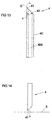
- Fig. 13 shows in a schematic drawing a medical injection device in the shape of a needle 4 comprising a hollow tube section 40 having a longitudinal inner wall 400.
- the medical injection device 4 serves to be injected for example into a vein or other vessel of a patient by penetration of the skin and tissue of the patient. In the injected state the medical injection device 4 rests in the patient's body and may serve to inject a medical fluid into the patient or to withdraw a fluid, for example blood or another body fluid, from the patient.
- the medical injection device comprises a sharpened tip 41, which - as schematically shown in Fig. 14 - serves to penetrate the patient's skin 5.
- a sharpened tip 41 which - as schematically shown in Fig. 14 - serves to penetrate the patient's skin 5.
- an opening 42 for fluid output or intake is arranged.
- the medical injection device 4 has an angle ⁇ measured between a cutting plane E and the direction of longitudinal extension L of the hollow tube section 40.
- the medical injection device 4 may for example be part of an infusion set, a syringe, a catheter or any other medical device employing a cannula for access to a patient's body.
- the medical injection device is at least partially made of a polymer nanocomposite material comprising a matrix polymer and a nanoparticle network.
- the nanoparticle network is formed by a formation of a substantially three-dimensional network of nanoparticles which at least partly are dispersed in the matrix polymer and interact with each other and/or with the matrix polymer.
- the polymer nanocomposite comprises two switching states. In a first switching state the polymer nanocomposite comprises a first stiffness characterized by a first tensile storage modulus. In a second switching state the polymer nanocomposite comprises a second stiffness characterized by a second tensile storage modulus which is smaller than the first tensile storage modulus.
- the polymer nanocomposite is switchable between the first switching state and the second switching state by exposing the polymer nanocomposite to a stimulus such as a water-containing composition, for example a body fluid or body tissue.
- compression-molded films of poly(vinyl acetate) (PVAc) with 16% v/v CNWs were prepared according to the method described by Shanmuganathan K. et al., "Bio-inspired mechanically-adaptive nanocomposites derived from cotton cellulose whiskers", J. Mater. Chem., 2010, 20, 180-186 .
- the storage modulus (E') for dry samples of this mechanically adaptive nanocomposite is 4.0 GPa and the material softens upon exposure to emulated physiological conditions (exposure to artificial cerebrospinal fluid at 37 °C for 1 week) to exhibit an E' of 5 MPa.
- Medical injection devices were machined from the films and had the following dimensions: a thickness of 510 ⁇ m, a width of 3 mm, a length of 25 mm, and a sharpened tip 41 at one end cut at a angle ⁇ of 31° (compare Fig. 13 ).
- a compression-molded film of PVOH with 16% v/v CNWs prepared by compression molding at 120 °C according to the protocol described in detail below, was used.
- the film had a thickness of 475 ⁇ m.
- the storage modulus (E') of dry samples of this mechanically adaptive nanocomposite is 9.0 GPa, and it softens upon exposure to emulated physiological conditions (exposure to artificial cerebrospinal fluid at 37 °C for 1 day) to exhibit an E' of 2 MPa.
- a compression-molded film of PVOH with 1.5% v/v TNWs prepared by compression molding at 150 °C according to the protocol described in detail below, was used.
- the film had a thickness of 300 ⁇ m.
- the storage modulus (E') of dry samples of this mechanically adaptive nanocomposite is 7.3 GPa.
- the film had a thickness of 550 ⁇ m.
- the storage modulus (E') of dry samples of this known material is 7.0 GPa and it softens upon exposure to emulated physiological conditions (exposure to artificial cerebrospinal fluid at 37 °C for 1 day) to exhibit an E' of 1 MPa.
- the rate of mechanical switching of the material is desirable for the rate of mechanical switching of the material to be rapid, preferably less than 10 minutes.
- the rate of mechanical switching of compression-molded films of neat PVOH was therefore determined by placing a dry film in the DMA submersion clamp without filling the submersion vessel with water.
- the sample had been prepared by compression molding at 120 °C according to the protocol described in detail below, and the film had a thickness of 80 ⁇ m.
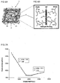
- the tensile measurement was started, under isothermal conditions, to establish the storage modulus of the dry film. As shown in Fig. 15 , for the sample under test the equilibriated value of the storage modulus after 45 minutes at room temperature was 7.5 GPa.
- Nanocomposite materials suitable for use in medical injection devices shall subsequently be described in terms of mechanically-adaptive nanocomposites comprising poly(vinyl alcohol) (PVOH) and cellulose nanowhiskers (NWs), whose mechanical properties change significantly upon exposure to physiological conditions. It shall be noted, however, that the invention is not limited to the use of such particular composites described herein, but may also be implemented using other matrix polymer materials and/or nanoparticles.
- PVOH poly(vinyl alcohol)
- NWs cellulose nanowhiskers
- Dynamic mechanical analysis results are presented in the following which show an enhancement of the tensile storage moduli (E') of the dry nanocomposites in comparison to the neat PVOH.
- the tensile storage modulus E' of the dry PVOH/TNW nanocomposites increases from 7.3 GPa for the neat polymer to 13.7 GPa for the nanocomposite with 16% v/v TNWs.
- the stiffness of the materials is greatly reduced upon exposure to aqueous conditions, on account of reduced NW-NW and NW-matrix interactions.
- Immersing the nanocomposites into artificial cerebrospinal fluid (ACSF) at body temperature (37 °C) causes a drastic drop in E', for example from 13.7 GPa to 160 MPa in the case of the nanocomposites containing 16% v/v TNWs.
- ASF cerebrospinal fluid
- Nanocomposites comprising 16% v/v CNWs exhibit an E' of 9.0 GPa in the dry state, which dropped to ⁇ 1 MPa upon exposure to artificial cerebrospinal fluid (ACSF) used for simulating physiological conditions.
- ASF cerebrospinal fluid
- cellulose nanofibers from plants (including wood, coconut husks, sisal, tunicates, cotton, ramie, straw, sugar beet, and many others) and animals (e.g. tunicates) is currently attracting significant attention, driven by the abundance and renewable nature of the biological sources and the attractive mechanical properties of nanocellulose.
- the latter originate from the hierarchical, uniaxially oriented structure of native cellulosic materials.
- Extended and aligned cellulose macromolecules D-glucose units, which are condensed through ⁇ (1 ⁇ 4) glycosidic bonds
- microfibrils in which they are stabilized through hydrogen bonds.
- microfibrils are largely crystalline, but they also contain regions that are less well ordered (i.e., largely amorphous).
- the cross-sectional dimension of the microfibrils ranges from 2-20 nm, depending on the origin of the cellulose.
- the elementary fibrils aggregate to form microfibrils with diameters of ⁇ 15-20 nm, which further aggregate into larger bundles and finally, with "blinders” consisting of amorphous lignin and hemicelluloses, into cellulosic fibers.
- These hierarchical structures can be deconstructed by mechanical and chemical processes, which yield highly crystalline cellulose nanofibers, collectively referred to as nanocelluloses or cellulose nanofibers.
- MFC microfibrillated cellulose
- CNC cellulose nanocrystals
- MFC also referred to as cellulose microfibrils, nanofibrillated cellulose, and cellulose nanofibrils
- milling the native cellulose followed by subsequent alkali and bleaching treatments to eliminate lignin and hemicelluloses.
- Mechanical disintegration of bleached wood pulp which has traditionally been carried out in highpressure homogenizers, separates the microfibrils and affords MFC in the form of fibrils with a diameter of ⁇ 20 nm and a length of several micrometers.
- the "amorphous defects" present in the native microfibrils are retained and the fibrous nature gives rise to entangled, network-like structures.
- CNCs also referred to as cellulose whiskers or nanowhiskers (NWs), nanocrystalline cellulose (NCC), cellulose microcrystals, and rod-like cellulose crystals
- NWs nanowhiskers
- NCC nanocrystalline cellulose
- rod-like cellulose crystals are produced by the hydrolysis of the bleached cellulose pulp with mineral acids.
- the hydrolysis serves to remove the amorphous cellulose domains, thereby also reducing the molecular weight.
- the remaining particles are usually separated by ultrasonic treatment.
- the dimensions of the resulting rod-like CNC particles depend primarily on the structure in the native material (i.e. the source) and to a lesser extent also on the hydrolysis conditions employed.
- CNCs are in the range of 5 - 25 nm and their length varies between 100 - 300 nm (in the case of wood and cotton) and several ⁇ m (in the case of tunicin). Since CNCs lack the amorphous domains present in the original microfibrils (and also in MFC), they display extremely high elastic moduli (100-150 GPa) and a high tensile strength ( ⁇ 10 GPa) in their long direction.
- a discussion of nanocellulose production and properties has been thoroughly treated in several reviews, such as Siqueira, G. et al., Polymers 2010, 2, 728 and Klemm, D. et al., Angew. Chem. Int. Ed. 2011, 50, 5438 .
- nanowhiskers derived from tunicates (TNWs) or cotton (CNWs) have been employed, both representing types of cellulose nanocrystals (CNCs), although in principle also other types of nanofibers may be used.
- TNWs were isolated from tunicates (Styela clava) collected from floating docks in Point View Marina (Narragansett, RI). The TNWs were prepared by sulfuric acid hydrolysis of the cellulose pulp. The protocol was based on the method described in Favier et al., Macromolecules 1995, 28, 6365 , utilized modifications as described in Shanmuganathan et al., ACS Appl. Mater.Interfaces 2010, 2, 165 .
- the bleached tunicate mantles were blended at high speed, yielding a fine cellulose pulp.
- Sulfuric acid (95-97%, 600 mL) was slowly (over the course of 2 h) added under vigorous mechanical stirring to an ice-cooled suspension of tunicate cellulose pulp in deionized water (6 g in 600 mL, 20 °C). After 500 mL of the acid had been added, the dispersion was removed from the ice bath and was heated to 40 °C during the addition of the final 100 mL of acid. After the acid addition was complete, the dispersion was heated to 60 °C and was kept at this temperature for 1 h under continuous stirring.
- the mixture was then cooled to room temperature, centrifuged (30 min at 3300 rpm), and the supernatant solution was decanted. Deionized water was added and the centrifugation step was repeated until the pH of the dispersion reached about 5. After the last centrifugation the resulting NWs were dialyzed in three successive 24 h treatments against deionized water to remove the last residues of the sulfuric acid. The suspension was diluted with deionized water (total volume 1 L) and sonicated for 18 h, before it was filtered through a No. 1 glass filter in order to remove any remaining aggregates. The concentration of the NWs in the final dispersion was determined gravimetrically to be ⁇ 3 mg/mL.
- This dispersion was freeze-dried using a VirTis BenchTop 2K XL lyophilizer with an initial temperature of 25 °C and a condenser temperature of -78 °C.
- the TNWs aerogel those produced was stored and used as needed.
- CNWs were isolated from Whatman filter paper with minor modifications to a procedure published in Capadona, J. R. et al., Biomacromolecules, 2009, 10, 712 . After sulfuric acid hydrolysis and dialysis treatment, the resulting dispersion was sonicated for 3 h and left to settle at room temperature for 18 h. The supernatant was then decanted off and the CNW dispersion was spray-dried using a Büchi Mini Spray Dryer (Model B-191) to yield dried CNWs as a white powder. The drying parameters were an inlet temperature of 110 °C, a flow rate of 4 mL/min, a nozzle airflow of 700 mL/min, an aspiration rate of 70%, and an outlet temperature of 60 °C.
- SEM Scanning Electron Microscopy
- the morphology of the NWs was examined by scanning electron microscopy (SEM) using a FEI XL 30 SIRON FEG microscope.
- a droplet of dilute aqueous NW dispersions (0.1 mg/mL) were deposited on a silicon wafer (TEDPELLA, Inc.) and allowed to dry. Then the samples were coated with a layer of gold ( ⁇ 5 nm), and observed with an accelerating voltage of 5 kV.
- TEM Transmission Electron Microscopy
- 3 ⁇ L of dilute aqueous NW dispersions (0.1 mg/mL) were deposited on carbon-coated grids (Electron Microscopy Sciences) and allowed to dry.
- the samples were examined with a Philips CM100 Biomicroscope operated at an accelerating voltage of 80 kV.
- NW dimensions were determined by analyzing 10 TEM images of NWs with a total of more than 100 individual NWs of which length and width were measured. The dimensions thus determined are reported as average values ⁇ standard error.
- Atomic Force Microscopy was carried out on a NanoWizard II (JPK Instruments) microscope. 10 ⁇ L of dilute aqueous NW dispersions (0.1 mg/mL) were deposited onto freshly cleaved mica (SPI Supplies Division of Structure Probe, Inc.) and allowed to dry. The scans were performed in tapping mode in air using silicon cantilevers (NANO WORLD, TESPA-50) with a scan rate of 1 line/sec.
- Conductometric Titration were performed to quantify the surface charges of NWs. 50 mg of the NWs were suspended into 10-15 mL of aqueous 0.01 M hydrochloric acid. After 5 min of stirring and 30 min of sonication, the suspensions were titrated with 0.01 M NaOH. The titration curves show the presence of a strong acid, corresponding to the excess of HCl, and a weak acid corresponding to the sulfate-ester surface groups (see Fig. 7A to 7C ).
- Dynamic Mechanical Analysis Mechanical properties of the PVOH/NW nanocomposites were characterized by dynamic mechanical analysis (DMA) using a TA instruments Model Q800. Tests were conducted in tensile mode using a temperature sweep method (0-140 °C) at a fixed frequency of 1 Hz, a strain amplitude of 30 ⁇ m, a heating rate of 5 °C/min, and a gap distance between jaws of ⁇ 10 mm. The samples were prepared by cutting strips from the films with a width of ⁇ 6 mm. To determine the mechanical properties of the films in the wet state, the samples were swelled in ACSF at 37 °C for periods of 1 week and 1 month.
- DMA experiments were conducted in tensile mode with a submersion clamp, which allowed measurements while the samples were immersed in ACSF.
- the temperature sweeps were done in the range of 23-75 °C with a heating rate of 1 °C/min, a constant frequency of 1 Hz, a strain amplitude of 30 ⁇ m, and a fixed gap distance between jaws of 15 mm.
- DSC Differential Scanning Calorimetry
- the NWs used in this study were isolated from tunicates (TNWs) and cotton (CNWs) by sulfuric acid hydrolysis, using protocols that represent modified versions of well-established methods.
- CNWs silk-drying was used to isolate the dry NWs (see Experimental Section).
- Polymer nanocomposites with TNWs have consistently been shown to exhibit superior mechanical properties than those with CNWs, a fact that is mainly credited to their higher aspect ratio ( ⁇ 70 vs. ⁇ 10) and on-axis stiffness (tensile modulus ⁇ 143 vs. ⁇ 105 GPa).
- CNWs are more viable for commercial exploitation because they are isolated from an abundant and sustainable bio-source.
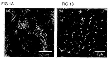
- NWs Due to their high density of strongly interacting surface hydroxyl groups, NWs have a strong tendency for self-association.30,43,46 Atomic force and electron microscopy of the NWs confirm that re-dispersion of the dried materials in water is readily possible ( Fig. 1 , and Fig. 8A to 8D ).
- the dimensions of the TNWs determined from TEM micrographs, were an average length and width of 2500 ⁇ 1000 nm and 30 ⁇ 5 nm, respectively.
- the average aspect ratio (A, defined as length to diameter (width) ratio, l/w) of the TNWs is therefore 83.
- the charge density of negatively charged sulphate esters on the NW surface that are introduced during hydrolysis has been suggested to modulate NW-NW interactions and to affect their dispersability.
- the density of sulfate groups of the present TNWs was determined to be ⁇ 90 mmol/kg ( Fig. 7A ).
- the CNWs used here were measured to have an average length and width of 220 ⁇ 70 nm and 22 ⁇ 6 nm, respectively, resulting in an aspect ratio of about 10.
- the charge density on the surface of CNWs ( ⁇ 40 mmol/kg, see Fig. 7B and 7C ), is significantly lower than that of TNWs. While TNWs were dried and isolated by lyophilization, spray-drying was used for CNWs.
- PVOH solutions and NW dispersions were combined, and after solution-casting and evaporation of solvent, the resulting films were re-shaped by compression-molding to result films of the nanocomposite with 4-16% v/v NWs and a thickness of 70-100 ⁇ m. Due to the limited thermal stability of the nanocomposites above the melting temperature (T m ) of PVOH ( ⁇ 220 °C), the films were compressed at a temperature much below T m . PVOH/TNW nanocomposites were compression-molded at 150 °C without any visible color changes, while PVOH/CNW nanocomposites yellowed, when processed at this temperature ( Fig. 9A, 9B ).
- PVOH/CNW nanocomposites were processed at 120 °C, unless otherwise noted.
- differences in thermal degradation may possibly arise from a combination of effects that including differences in surface chemistry and charge density, which are related to the source of NWs.
- the thermal properties of PVOH/NW nanocomposites were determined using differential scanning calorimetry (DSC, Table 1).
- the DSC curves show that the T g (68 and 71 °C) and T m (216 and 206 °C) of the neat PVOH only slightly depends on the temperature at which the films were compression-molded. In both cases, the incorporation of NWs led to an increase of T g by approximately 10 °C, which interestingly was independent of the NW content.
- the width of the melting peak increases, and the degree of crystallinity ( ⁇ c ) increases slightly, perhaps on account of a small nucleation effect of the NWs. Also this effect was largely independent of the NW content.
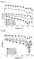
- Fig. 2A shows the tensile storage moduli (E') of the PVOH/TNW nanocomposites and a neat PVOH reference film in the dry state as a function of temperature.
- E' tensile storage moduli
- the neat PVOH matrix, processed at 150 °C exhibits an E' of 7.3 GPa.
- E' drastically decreases to 840 MPa at 100 °C ( ⁇ T g + 30 °C) due to a transition from the glassy to the rubbery regime at -70 °C, which is seen as a maximum in the tan ⁇ curves ( Fig. 2B ).
- PVOH/TNW nanocomposites containing 4 to 16 % v/v TNWs showed a significant increase in E' compared to the neat matrix below and above the T g .
- E' increased from 7.3 GPa (neat PVOH) to 13.7 GPa for the nanocomposite containing 16% v/v TNWs ( Fig. 2A and Table 2).
- a more significant reinforcement was observed above T g .
- the nanocomposite containing 16% v/v TNWs shows an E' of 5.4 GPa, which represents a seven-fold increase over the stiffness of the neat PVOH (840 MPa) at this temperature.
- the E' of nanocomposites prepared with CNWs exhibits a similar trend as observed for the TNW nanocomposites, although the stiffness increase was more modest.
- PVOH/CNW nanocomposite films yellowed upon compression molding at 150 °C and were thus processed at 120 °C.
- the E' of dry PVOH reference films, processed at 120 °C was found to be slightly lower than that of the neat PVOH processed at 150 °C ( Fig. 2A , 2C , and Table 2). For example, at 25 °C E' values of 7.3 and 7.0 GPa were measured.
- PVOH/CNW nanocomposite with 16% v/v CNWs exhibited a E' of 9.0 GPa at 25 °C, which is higher than that of the neat PVOH (7.0 GPa), but lower than the E' of 13.7 GPa of the TNW nanocomposite with the same NW content.
- T g (at 100 °C) E' of this nanocomposite was 1.4 GPa, which represent a two-fold enhancement over the stiffness of the neat polymer ( Fig. 2C and Table 2).
- the lower reinforcement displayed by the CNWs compared to the TNWs is consistent with previous findings and is attributed at least in part to lower aspect ratio and stiffness of CNWs.
- Fig. 2B and 2D display the loss factor (tan ⁇ ) curves of neat PVOH and the two series of nanocomposites as a function of temperature. Tan ⁇ is the ratio of loss modulus to storage modulus E"/E' of the material and is indicative of its damping behavior. All curves show a single relaxation peak centered at T ⁇ , which corresponds to the T g determined by DSC.
- the introduction of NWs led to a reduction in peak intensity and a shift of T ⁇ to higher temperature compared to the neat PVOH films. This trend is attributed to the reduced mobility of PVOH chains in the amorphous phase due to the presence of the NWs.
- Table 3 shows a comparison of the E' values of the dry PVOH/NW nanocomposites studied here with previously reported mechanically-adaptive nanocomposites based on a range of polymer matrices. The data are quoted for a filler content of ⁇ 16% v/v. The comparison shows that the stiffness of the present PVOH/TNW nanocomposites is, at 25 °C as well as T g + 30 °C, more than three times higher than that of the stiffest mechanically-adaptive nanocomposites reported to date. This implies that a good dispersion of the NWs has been achieved in the PVOH matrix and supports the conclusion that strong H-bonding interactions between the NWs and the polymer matrix indeed increase the reinforcing effect of the cellulose.
- a polymer nanocomposite 1 comprises a matrix polymer 2, in the particular embodiment described herein PVOH, and a nanofiber network formed by a substantially three-dimensional network of nanofibers 3, in the particular embodiment described herein tunicate nanowhiskers (TNWs) or cotton nanowhiskers (CNWs).
- the matrix polymer comprises crystalline regions 20 and amorphous regions 21.
- the matrix polymer 2, in this case PVOH is capable of forming hydrogen bonds with the nanofibers 3 (cellulose nanowhiskers NWs, in this case tunicate nanowhiskers TNWs or cotton nanowhiskers CNWs).
- Such hydrogen bonding (H-bonding) interactions between the NWs and the matrix polymer 2 are believed to have a reinforcing effect of the polymer nanocomposite 1 at least in the dry state of the polymer nanocomposite 1 (first switching state).
- first switching state Upon subjection to a stimulus, for example upon exposure to a water-containing composition, such hydrogen bonds at least partially are released, yielding a reduction in stiffness in the soft state (second switching state) of the nanocomposite 1.
- the mechanical reinforcement in optimally assembled NW nanocomposites is caused by the formation of a percolating NW network, in which stress transfer is facilitated by hydrogen bonding between the NWs.
- the stiffness of these materials can be described by a percolation model that has been successfully used to predict the mechanical behavior of heterogeneous materials, such as polymer blends and nanocomposites.
- Detailed information about the percolation model and its use for modeling NWs-based nanocomposites has been reported for example in Samir, M. A. et al., Biomacromolecules, 2005, 6, 612 . Fig.
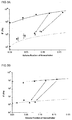
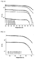
- 3A and 3B show the predictions for the two nanocomposites series made by the percolation model, along with experimentally determined values of dry PVOH/NW nanocomposites at 100 °C, i.e., at ⁇ T g + 30 °C.
- aspect ratios (A) of 83 and 10 were used for TNWs and CNWs, respectively, and storage moduli E' s of 840 MPa (for TNW nanocomposites processed at 150 °C) and 700 MPa (for CNW nanocomposites processed at 120 °C) were employed for the neat polymer matrix at 100 °C (as determined by DMA).
- the tensile storage modulus of the NW phase, E' r was in previous studies derived by either measuring the stiffness of a neat TNW or CNW film or by fitting the model against the experimentally determined properties of the nanocomposites and using E' r as a fit parameter. While the morphology (and therewith the stiffness) of a neat NW film depends strongly on the processing conditions and has little resemblance to that of a NW network within a polymer matrix, the E' r values of 5 - 24 GPa for TNW-based, and 0.6 - 5 GPa for CNW-based nanocomposites determined by these approaches appeared to roughly match.
- E' r values of 80 GPa and 10 GPa are required to fit the model to the data for the TNW-based and CNW-based nanocomposites with PVOH studied here ( Fig. 3A and 3B ).
- a comparison of the data for several other TNW-based nanocomposites shows that for a given NW content, E' increases with the polarity of the polymer matrix (PS ⁇ PVAc ⁇ Epoxy), suggesting that systems with pronounced NW-polymer interactions may exhibit larger reinforcement due to factors that are not explicitly accounted for in the percolation model.
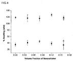
- the swelling behavior of the nanocomposites in physiological conditions was investigated by immersing the materials into artificial cerebrospinal fluid (ACSF) at 37 °C to mimic physiological conditions. It is known that heat-treated PVOH is no longer water soluble, and that the processing temperature of PVOH affects the permeability of the material and thereby the potential for water uptake. Indeed, the swelling characteristics of the materials studied here were found to be strongly dependent on the temperature used for compression molding, but not the type or content of NWs. Neat PVOH and PVOH/TNW nanocomposite films processed at 150 °C exhibit ⁇ 40% w/w swelling, whereas neat PVOH films and PVOH/CNW nanocomposites processed at 120 °C exhibit approximately ⁇ 120% w/w swelling ( Fig.
- PVOH/CNW nanocomposite films reached an equilibrated swelling within 24 hours and maintained their integrity for at least one week.
- a comparison of the swelling data of the present PVOH/TNW and the previously investigated PVAc/TNW nanocomposites29 shows that the PVOH-based nanocomposites swell much less than their PVAc-based counterparts.
- the PVAc/TNW nanocomposites comprising 16.5% v/v TNWs displayed a degree of swelling of ⁇ 80%, while the PVOH/TNW nanocomposites shows ⁇ 40% w/w of swelling with 16% v/v NWs.
- the mechanical properties of ACSF-swollen PVOH/NW nanocomposites were determined by DMA using a submersion clamp set-up, which allowed the samples to be immersed in ACSF during the measurements.
- Neat PVOH films softened substantially upon submersion in ACSF for one week and exhibited mechanical properties that appear to be correlated with their swelling behavior.
- Neat PVOH films processed at 150 °C displayed a change in E' from ⁇ 7.3 GPa (dry) to ⁇ 11 MPa (ACSF-swollen), whereas E' for neat PVOH films processed at 120 °C changed from 7.0 GPa to ⁇ 1 MPa.
- the ACSF-swollen PVOH/TNW nanocomposites display an E' that is higher than of the neat PVOH films ( Fig.
- PVOH/CNW films processed at 150 °C show some yellowing, their dry-state mechanical properties are largely comparable to those of the material processed at 120 °C, and (on account of less swelling) a higher modulus in the soft state is achieved, suggesting that whatever effect is responsible for the yellowing, it is not negatively impacting the material's mechanical characteristics.
- PVOH is used as a matrix, not only the NW type and content but also the processing temperature can be used to tailor the mechanical contrast of cellulose NWs-based, water-responsive, mechanically adaptive nanocomposites.
- water-responsive, mechanically-adaptive nanocomposites based on polymer nanocomposites described herein in particular such nanocomposites using PVOH as matrix polymer and TNWs or CNWs as nanofibers, may offer an initial stiffness that is significantly higher than that of previous generations of such responsive materials.
- PVOH as a matrix polymer into which nanofibers such as NWs are incorporated may yield tensile storage moduli of PVOH/NW nanocomposites which - in both the glassy and rubbery regime - in the first switching state are significantly higher than those of comparable, other nanocomposites. It appears that in addition to NW-NW interactions, polymer-NW interactions, which are promoted by the strong propensity of PVOH to form hydrogen bonds, may be a factor in this context. Another factor is the possibility of controlling the swelling characteristics of the PVOH matrix, and therewith the properties of water- or ACSF-swollen nanocomposites, via the processing conditions.
- the change in stiffness upon switching between the switching states of the TNW-based nanocomposites upon exposure to ACSF could be varied between a 90-fold to a 200-fold modulus change.
- a desired modulus change upon exposure to a suitable stimulus may be set.
- PVOH/CNW nanocomposites Although not as stiff initially in the dry state compared to PVOH/TNW, PVOH/CNW nanocomposites exhibit a larger mechanical contrast (up to 900-fold), as they soften more than TNW-based nanocomposites. This effect possibly is related to the lower reinforcing power of CNWs. Despite the fact that decomposition of the CNW-containing materials starts around 150 °C, the nanocomposites maintain useful mechanical properties. Therefore, one could envision employing a higher processing temperature for PVOH/CNW nanocomposites to further increase the stiffness of the water-swollen state.
- the invention is not limited to the embodiments described above but may be carried out also by entirely different embodiments.
- other matrix polymer materials such as polyamide may be used rather than PVOH.
- nanofibers other than tunicate nanowhiskers (TNW) or cotton nanowhiskers (CNW), for example cellulose nanowhiskers not derived from tunicates or cotton, may be employed.
Landscapes
- Health & Medical Sciences (AREA)
- Engineering & Computer Science (AREA)
- Life Sciences & Earth Sciences (AREA)
- General Health & Medical Sciences (AREA)
- Veterinary Medicine (AREA)
- Public Health (AREA)
- Animal Behavior & Ethology (AREA)
- Chemical & Material Sciences (AREA)
- Anesthesiology (AREA)
- Biomedical Technology (AREA)
- Hematology (AREA)
- Heart & Thoracic Surgery (AREA)
- Composite Materials (AREA)
- Nanotechnology (AREA)
- Epidemiology (AREA)
- Materials Engineering (AREA)
- Vascular Medicine (AREA)
- General Physics & Mathematics (AREA)
- Crystallography & Structural Chemistry (AREA)
- Biophysics (AREA)
- Pulmonology (AREA)
- Condensed Matter Physics & Semiconductors (AREA)
- Physics & Mathematics (AREA)
- Materials For Medical Uses (AREA)
Claims (16)
- Medizinische Injektionsvorrichtung (4) zum Führen von Flüssigkeit mit umschaltbaren mechanischen Eigenschaften, umfassend einen hohlen Rohrabschnitt (40) mit einer Innenbohrung (400), wobei der hohle Rohrabschnitt (40) wenigstens teilweise aus einem Material besteht, das umschaltbare mechanische Eigenschaften aufweist, so dass das Material in einem ersten Schaltzustand eine erste Steifigkeit aufweist, die durch einen ersten Zug-Speichermodul (E') gekennzeichnet ist, in einem zweiten Schaltzustand eine zweite Steifigkeit aufweist, die durch einen zweiten Zug-Speichermodul (E') gekennzeichnet ist, der kleiner als der erste Zug-Speichermodul ist und von dem ersten Schaltzustand in den zweiten Schaltzustand umschaltbar ist, indem das Material gegenüber einem Reiz exponiert wird,
dadurch gekennzeichnet,
dass das Material ein Polymer-Nanokomposit (1) umfasst, umfassend- ein Matrixpolymer (2) und- ein Nanopartikelnetzwerk, wobei das Nanopartikelnetzwerk durch Bilden eines im Wesentlichen dreidimensionalen Netzwerks von Nanopartikeln (3) gebildet ist, die in das Matrixpolymer (2) einverleibt sind und miteinander und/oder mit dem Matrixpolymer (2) wechselwirken,wobei die Nanopartikel (3) Nanofasern umfassen und
wobei der Reiz Wechselwirkungen der Nanopartikel (3) miteinander und/oder zwischen den Nanopartikeln (3) und dem Matrixpolymer (2) beeinflusst. - Medizinische Injektionsvorrichtung (4) gemäß Anspruch 1, wobei der erste Zug-Speichermodul (E') größer als 3,5 GPa ist, vorzugsweise 6 GPa, höchst bevorzugt größer als 9 GPa, und/oder wobei der zweite Zug-Speichermodul (E') kleiner als 1 GPa ist.
- Medizinische Injektionsvorrichtung (4) gemäß einem der Ansprüche 1 bis 2, wobei das Polymer-Nanokomposit (1) durch Anwenden eines Verfahrens umfassend die Schritte:- Bereitstellen des Matrixpolymers (2),- Einverleiben des Nanopartikelnetzwerks in das Matrixpolymer (2), um ein intermediäres Gemisch zu erhalten,- Unterwerfen des intermediären Gemischs an einen Wärmebehandlungsschritt, der Exposition gegenüber einer Temperatur von gleich oder höher als 100 °C umfasst,erhältlich ist.
- Medizinische Injektionsvorrichtung (4) gemäß Anspruch 3, wobei der Wärmebehandlungsschritt Formpressen des Polymer-Nanokomposits (1) bei einer Temperatur von gleich oder höher als 100 °C umfasst.
- Medizinische Injektionsvorrichtung (4) gemäß Anspruch 4 oder 5,
wobei das intermediäre Gemisch vor dem Wärmebehandlungsschritt einem Trocknungsschritt unterworfen wird, der Exposition gegenüber einer erhöhten Temperatur von 30 °C bis 80 °C über einen ausgedehnten Zeitraum von 1 Tag bis 10 Tagen umfasst und/oder
wobei der Trocknungsschritt umfasst:- einen ersten Trocknungsschritt, der Exposition gegenüber einer ersten Trocknungstemperatur von 30 °C bis 50 °C, beispielsweise 35 °C, über einen ersten Zeitraum von 1 Tag bis 10 Tagen, beispielsweise 5 Tagen, umfasst, und- einen zweiten Trocknungsschritt, der Exposition gegenüber einer zweiten Trocknungstemperatur von 50 °C bis 80 °C, beispielsweise 70 °C, über einen zweiten Zeitraum von 5 h bis 48 h, beispielsweise 24 h, umfasst. - Medizinische Injektionsvorrichtung (4) gemäß einem der vorstehenden Ansprüche, wobei das Matrixpolymer (2) ein Polymer umfasst, das fähig ist, nichtkovalente Wechselwirkungen, insbesondere Wasserstoffbrücken, mit den Nanopartikeln (3) zu bilden.
- Medizinische Injektionsvorrichtung (4) gemäß einem der vorstehenden Ansprüche, wobei das Matrixpolymer (2) wenigstens ein Vinylpolymer, wie z. B. Polyvinylalkohol, Poly(acrylsäure), Poly(acrylamid), Poly(vinylpyridin), ein Copolymer von wenigstens einem dieser Monomere, ein Polykondensat, wie z. B. Polyamid oder Polyester, ein Polysaccharid, wie z. B. Cellulose, Stärke, Alginate, Pectine, Hyaluronan, Chitin, Chitosan oder wenigstens eines seiner Derivate und/oder ein Protein umfasst.
- Medizinische Injektionsvorrichtung (4) gemäß einem der vorstehenden Ansprüche, wobei die Nanopartikel (3) fähig sind, nichtkovalente Wechselwirkungen, insbesondere Wasserstoffbrücken, miteinander und/oder mit dem Matrixpolymer (2) zu bilden.
- Medizinische Injektionsvorrichtung (4) gemäß Anspruch 9, wobei die Nanofasern (3) Cellulose-Nanowhisker umfassen, vorzugsweise wobei die Nanofasern (3) aus Tunicaten oder Baumwolle abgeleitete Cellulose-Nanowhisker umfassen.
- Medizinische Injektionsvorrichtung (4) gemäß einem der Ansprüche 9 bis 10, wobei die Nanofasern (3) ein Aspektverhältnis von größer als 5 aufweisen, vorzugsweise größer als 10, bevorzugter größer als 50, höchst bevorzugt größer als 80.
- Medizinische Injektionsvorrichtung (4) gemäß einem der vorstehenden Ansprüche, wobei das Polymer-Nanokomposit (1) einen Gehalt von 1 % bis 30 %, vorzugsweise 2 % bis 25 %, bevorzugter 3 % bis 20 % v/v an Nanopartikeln (3) umfasst.
- Medizinische Injektionsvorrichtung (4) gemäß einem der vorstehenden Ansprüche, wobei das Polymer-Nanokomposit (1) durch einen Reiz, der die Wechselwirkungen der Nanopartikel (3) miteinander und/oder zwischen den Nanopartikeln (3) und dem Matrixpolymer (2) verringert, von dem ersten Schaltzustand in den zweiten Schaltzustand umschaltbar ist und das Polymer-Nanokomposit (1) durch einen Reiz, der die Wechselwirkungen der Nanopartikel (3) miteinander und/oder zwischen den Nanopartikeln (3) und dem Matrixpolymer (2) verstärkt, von dem zweiten Schaltzustand in den ersten Schaltzustand umschaltbar ist.
- Medizinische Injektionsvorrichtung (4) gemäß einem der vorstehenden Ansprüche,
wobei das Polymer-Nanokomposit (1) von dem ersten Schaltzustand in den zweiten Schaltzustand umschaltbar ist, indem das Polymer-Nanokomposit (1) an eine wasserhaltige Zusammensetzung ausgesetzt wird und/oder
wobei das Polymer-Nanokomposit (1) umschaltbar ist, indem das Polymer-Nanokomposit (1) an eine erhöhte Temperatur zwischen 30 °C und 50 °C, vorzugsweise 35 °C bis 40 °C, ausgesetzt wird. - Medizinische Injektionsvorrichtung (4) gemäß einem der vorstehenden Ansprüche,
wobei das Verhältnis der Speichermodule der beiden Umschaltzustände höher als 20 ist, vorzugsweise höher als 50, bevorzugter höher als 100 und höchst bevorzugt höher als 500 und/oder
wobei das Polymer-Nanokomposit (3) im Wesentlichen isotrope mechanische Eigenschaften zeigt und/oder
wobei der hohle Rohrabschnitt (40) eine Wanddicke zwischen 50 µm und 1000 µm aufweist, vorzugsweise zwischen 100 µm und 500 µm. - Verfahren zum Herstellen einer medizinischen Injektionsvorrichtung (4) mit umschaltbaren mechanischen Eigenschaften, umfassend einen hohlen Rohrabschnitt (40) mit einer Innenbohrung (400), wobei der hohle Rohrabschnitt (40) wenigstens teilweise aus einem Material besteht, das umschaltbare mechanische Eigenschaften aufweist, so dass das Material in einem ersten Schaltzustand eine erste Steifigkeit aufweist, die durch einen ersten Zug-Speichermodul (E') gekennzeichnet ist, in einem zweiten Schaltzustand eine zweite Steifigkeit aufweist, die durch einen zweiten Zug-Speichermodul (E') gekennzeichnet ist, der kleiner als der erste Zug-Speichermodul ist und von dem ersten Schaltzustand in den zweiten Schaltzustand umschaltbar ist, indem das Material gegenüber einem Reiz exponiert wird,
dadurch gekennzeichnet,
dass das Material ein Polymer-Nanokomposit umfasst, das hergestellt wird durch- Bereitstellen eines Matrixpolymers (2) und- Einverleiben eines Nanopartikelnetzwerks in das Matrixpolymer (2), wobei das Nanopartikelnetzwerk durch Bilden eines im Wesentlichen dreidimensionalen Netzwerks von Nanopartikeln (3) gebildet wird, die in das Matrixpolymer (2) einverleibt werden und miteinander und/oder mit dem Matrixpolymer (2) wechselwirken, wobei der Reiz Wechselwirkungen der Nanopartikel (3) miteinander und/oder zwischen den Nanopartikeln (3) und dem Matrixpolymer (2) beeinflusst,wobei die Nanopartikel (3) Nanofasern umfassen. - Verfahren zum Induzieren einer Steifigkeitsveränderung in einer medizinischen Injektionsvorrichtung (4) mit umschaltbaren mechanischen Eigenschaften und umfassend einen hohlen Rohrabschnitt (40) mit einer Innenbohrung (400), wobei der hohle Rohrabschnitt (40) wenigstens teilweise aus einem Material besteht, das umschaltbare mechanische Eigenschaften aufweist, so dass das Material in einem ersten Schaltzustand eine erste Steifigkeit aufweist, die durch einen ersten Zug-Speichermodul (E') gekennzeichnet ist, in einem zweiten Schaltzustand eine zweite Steifigkeit aufweist, die durch einen zweiten Zug-Speichermodul (E') gekennzeichnet ist, der kleiner als der erste Zug-Speichermodul ist und von dem ersten Schaltzustand in den zweiten Schaltzustand umschaltbar ist, indem das Material gegenüber einem Reiz exponiert wird,
dadurch gekennzeichnet,
dass das Material ein Polymer-Nanokomposit (1) umfasst, umfassend- ein Matrixpolymer (2) und- ein Nanopartikelnetzwerk, wobei das Nanopartikelnetzwerk durch Bilden eines im Wesentlichen dreidimensionalen Netzwerks von Nanopartikeln (3) gebildet ist, die in das Matrixpolymer (2) einverleibt sind und miteinander und/oder mit dem Matrixpolymer (2) wechselwirken,wobei die Nanopartikel (3) Nanofasern umfassen.
wobei der Reiz das Polymer-Nanokomposit zwischen dem ersten Schaltzustand und dem zweiten Schaltzustand umschaltet, indem er Wechselwirkungen der Nanopartikel (3) miteinander und/oder zwischen den Nanopartikeln (3) und dem Matrixpolymer (2) beeinflusst,
Priority Applications (1)
| Application Number | Priority Date | Filing Date | Title |
|---|---|---|---|
| EP13759994.0A EP2895221B1 (de) | 2012-09-14 | 2013-09-04 | Medizinische injektionsvorrichtung |
Applications Claiming Priority (4)
| Application Number | Priority Date | Filing Date | Title |
|---|---|---|---|
| US201261700995P | 2012-09-14 | 2012-09-14 | |
| EP12184405 | 2012-09-14 | ||
| EP13759994.0A EP2895221B1 (de) | 2012-09-14 | 2013-09-04 | Medizinische injektionsvorrichtung |
| PCT/EP2013/068227 WO2014040886A1 (en) | 2012-09-14 | 2013-09-04 | Medical injection device |
Publications (2)
| Publication Number | Publication Date |
|---|---|
| EP2895221A1 EP2895221A1 (de) | 2015-07-22 |
| EP2895221B1 true EP2895221B1 (de) | 2016-05-18 |
Family
ID=46967991
Family Applications (1)
| Application Number | Title | Priority Date | Filing Date |
|---|---|---|---|
| EP13759994.0A Not-in-force EP2895221B1 (de) | 2012-09-14 | 2013-09-04 | Medizinische injektionsvorrichtung |
Country Status (4)
| Country | Link |
|---|---|
| EP (1) | EP2895221B1 (de) |
| DK (1) | DK2895221T3 (de) |
| ES (1) | ES2585830T3 (de) |
| WO (1) | WO2014040886A1 (de) |
Families Citing this family (1)
| Publication number | Priority date | Publication date | Assignee | Title |
|---|---|---|---|---|
| WO2023036682A1 (en) | 2021-09-07 | 2023-03-16 | Fresenius Kabi Deutschland Gmbh | Catheter for percutaneous feeding |
Family Cites Families (5)
| Publication number | Priority date | Publication date | Assignee | Title |
|---|---|---|---|---|
| US4846812A (en) * | 1988-03-22 | 1989-07-11 | Menlo Care, Inc. | Softening catheter |
| DE10117286A1 (de) * | 2001-04-06 | 2002-10-17 | Disetronic Licensing Ag | Weiche Kanüle |
| KR100481420B1 (ko) * | 2002-10-22 | 2005-04-08 | 주식회사 이래화학 | 생분해성 소재를 이용한 혈관주사용 주사바늘 |
| ES2285412T3 (es) * | 2003-01-17 | 2007-11-16 | Disetronic Licensing Ag | Aguja flexible de inyeccion. |
| DE102005001704A1 (de) * | 2005-01-13 | 2006-07-20 | Disetronic Licensing Ag | Biegsame Einstechnadel |
-
2013
- 2013-09-04 WO PCT/EP2013/068227 patent/WO2014040886A1/en not_active Ceased
- 2013-09-04 DK DK13759994.0T patent/DK2895221T3/en active
- 2013-09-04 ES ES13759994.0T patent/ES2585830T3/es active Active
- 2013-09-04 EP EP13759994.0A patent/EP2895221B1/de not_active Not-in-force
Also Published As
| Publication number | Publication date |
|---|---|
| ES2585830T3 (es) | 2016-10-10 |
| DK2895221T3 (en) | 2016-08-22 |
| EP2895221A1 (de) | 2015-07-22 |
| WO2014040886A1 (en) | 2014-03-20 |
Similar Documents
| Publication | Publication Date | Title |
|---|---|---|
| Rebouillat et al. | State of the art manufacturing and engineering of nanocellulose: a review of available data and industrial applications | |
| Li et al. | Natural silk nanofibrils as reinforcements for the preparation of chitosan-based bionanocomposites | |
| Feng et al. | Facile preparation of biocompatible silk fibroin/cellulose nanocomposite films with high mechanical performance | |
| Huan et al. | Electrospun poly (lactic acid)-based fibrous nanocomposite reinforced by cellulose nanocrystals: impact of fiber uniaxial alignment on microstructure and mechanical properties | |
| Yang et al. | Morphological, mechanical and thermal properties of poly (lactic acid)(PLA)/cellulose nanofibrils (CNF) composites nanofiber for tissue engineering | |
| Kalia et al. | Cellulose‐based bio‐and nanocomposites: a review | |
| Jayanth et al. | A review on biodegradable polymeric materials striving towards the attainment of green environment | |
| Rostamabadi et al. | Cellulose nanofibers, nanocrystals, and bacterial nanocellulose: Fabrication, characterization, and their most recent applications | |
| Abdul Khalil et al. | Cellulosic nanocomposites from natural fibers for medical applications: A review | |
| JP4874930B2 (ja) | デンプン繊維の製造方法 | |
| CN113549227A (zh) | 化学交联水凝胶及其微球、制备方法与应用 | |
| Wan et al. | Investigation of mechanical properties and degradability of multi-channel chitosan–polycaprolactone/collagen conduits | |
| JP2016502612A (ja) | N‐アセチル‐d‐グルコサミン基の6位が選択的に酸化されたヒアルロナンをベースとするエンドレスファイバー,その調製及び使用,該エンドレスファイバーから成る糸,ステープル,織り糸,生地,並びにその修飾方法 | |
| CN110698731A (zh) | 一种多功能复合生物材料、制备方法及其应用 | |
| Zhang et al. | Fabrication of a high-toughness polyurethane/fibroin composite without interfacial treatment and its toughening mechanism | |
| Ghalia et al. | Mechanical and biodegradability of porous PCL/PEG copolymer-reinforced cellulose nanofibers for soft tissue engineering applications | |
| WO2014040885A2 (en) | Polymer nanocomposite having switchable mechanical properties | |
| EP2895221B1 (de) | Medizinische injektionsvorrichtung | |
| Torres et al. | Cellulose based blends, composites and nanocomposites | |
| Li et al. | Preparation and properties of nano-cellulose/sodium alginate composite hydrogel | |
| Nessiani et al. | Bionanocomposites for biomedical applications: fabrication and properties | |
| CN114404304B (zh) | 一种可降解的消毒护肤湿巾及其制备方法 | |
| Singh et al. | Cellulosic nanowhiskers: preparation and drug delivery application | |
| Uddin et al. | A novel approach to reduce fibrillation of PVA fibres using cellulose whiskers | |
| Chaudhary et al. | Potential of Different Types of Biocomposites for Health Treatment: Synthesis and Applications |
Legal Events
| Date | Code | Title | Description |
|---|---|---|---|
| PUAI | Public reference made under article 153(3) epc to a published international application that has entered the european phase |
Free format text: ORIGINAL CODE: 0009012 |
|
| 17P | Request for examination filed |
Effective date: 20150414 |
|
| AK | Designated contracting states |
Kind code of ref document: A1 Designated state(s): AL AT BE BG CH CY CZ DE DK EE ES FI FR GB GR HR HU IE IS IT LI LT LU LV MC MK MT NL NO PL PT RO RS SE SI SK SM TR |
|
| AX | Request for extension of the european patent |
Extension state: BA ME |
|
| DAX | Request for extension of the european patent (deleted) | ||
| GRAP | Despatch of communication of intention to grant a patent |
Free format text: ORIGINAL CODE: EPIDOSNIGR1 |
|
| INTG | Intention to grant announced |
Effective date: 20160111 |
|
| GRAS | Grant fee paid |
Free format text: ORIGINAL CODE: EPIDOSNIGR3 |
|
| GRAA | (expected) grant |
Free format text: ORIGINAL CODE: 0009210 |
|
| AK | Designated contracting states |
Kind code of ref document: B1 Designated state(s): AL AT BE BG CH CY CZ DE DK EE ES FI FR GB GR HR HU IE IS IT LI LT LU LV MC MK MT NL NO PL PT RO RS SE SI SK SM TR |
|
| REG | Reference to a national code |
Ref country code: GB Ref legal event code: FG4D |
|
| REG | Reference to a national code |
Ref country code: CH Ref legal event code: EP |
|
| REG | Reference to a national code |
Ref country code: IE Ref legal event code: FG4D Ref country code: AT Ref legal event code: REF Ref document number: 799873 Country of ref document: AT Kind code of ref document: T Effective date: 20160615 |
|
| REG | Reference to a national code |
Ref country code: DE Ref legal event code: R096 Ref document number: 602013007743 Country of ref document: DE Ref country code: CH Ref legal event code: NV Representative=s name: AMMANN PATENTANWAELTE AG BERN, CH |
|
| REG | Reference to a national code |
Ref country code: NL Ref legal event code: FP |
|
| REG | Reference to a national code |
Ref country code: DK Ref legal event code: T3 Effective date: 20160815 |
|
| REG | Reference to a national code |
Ref country code: SE Ref legal event code: TRGR |
|
| REG | Reference to a national code |
Ref country code: LT Ref legal event code: MG4D Ref country code: FR Ref legal event code: PLFP Year of fee payment: 4 |
|
| REG | Reference to a national code |
Ref country code: ES Ref legal event code: FG2A Ref document number: 2585830 Country of ref document: ES Kind code of ref document: T3 Effective date: 20161010 |
|
| REG | Reference to a national code |
Ref country code: NO Ref legal event code: T2 Effective date: 20160518 |
|
| PG25 | Lapsed in a contracting state [announced via postgrant information from national office to epo] |
Ref country code: LT Free format text: LAPSE BECAUSE OF FAILURE TO SUBMIT A TRANSLATION OF THE DESCRIPTION OR TO PAY THE FEE WITHIN THE PRESCRIBED TIME-LIMIT Effective date: 20160518 Ref country code: FI Free format text: LAPSE BECAUSE OF FAILURE TO SUBMIT A TRANSLATION OF THE DESCRIPTION OR TO PAY THE FEE WITHIN THE PRESCRIBED TIME-LIMIT Effective date: 20160518 |
|
| PG25 | Lapsed in a contracting state [announced via postgrant information from national office to epo] |
Ref country code: GR Free format text: LAPSE BECAUSE OF FAILURE TO SUBMIT A TRANSLATION OF THE DESCRIPTION OR TO PAY THE FEE WITHIN THE PRESCRIBED TIME-LIMIT Effective date: 20160819 Ref country code: RS Free format text: LAPSE BECAUSE OF FAILURE TO SUBMIT A TRANSLATION OF THE DESCRIPTION OR TO PAY THE FEE WITHIN THE PRESCRIBED TIME-LIMIT Effective date: 20160518 Ref country code: HR Free format text: LAPSE BECAUSE OF FAILURE TO SUBMIT A TRANSLATION OF THE DESCRIPTION OR TO PAY THE FEE WITHIN THE PRESCRIBED TIME-LIMIT Effective date: 20160518 Ref country code: LV Free format text: LAPSE BECAUSE OF FAILURE TO SUBMIT A TRANSLATION OF THE DESCRIPTION OR TO PAY THE FEE WITHIN THE PRESCRIBED TIME-LIMIT Effective date: 20160518 Ref country code: PT Free format text: LAPSE BECAUSE OF FAILURE TO SUBMIT A TRANSLATION OF THE DESCRIPTION OR TO PAY THE FEE WITHIN THE PRESCRIBED TIME-LIMIT Effective date: 20160919 |
|
| PG25 | Lapsed in a contracting state [announced via postgrant information from national office to epo] |
Ref country code: RO Free format text: LAPSE BECAUSE OF FAILURE TO SUBMIT A TRANSLATION OF THE DESCRIPTION OR TO PAY THE FEE WITHIN THE PRESCRIBED TIME-LIMIT Effective date: 20160518 Ref country code: CZ Free format text: LAPSE BECAUSE OF FAILURE TO SUBMIT A TRANSLATION OF THE DESCRIPTION OR TO PAY THE FEE WITHIN THE PRESCRIBED TIME-LIMIT Effective date: 20160518 Ref country code: EE Free format text: LAPSE BECAUSE OF FAILURE TO SUBMIT A TRANSLATION OF THE DESCRIPTION OR TO PAY THE FEE WITHIN THE PRESCRIBED TIME-LIMIT Effective date: 20160518 Ref country code: SK Free format text: LAPSE BECAUSE OF FAILURE TO SUBMIT A TRANSLATION OF THE DESCRIPTION OR TO PAY THE FEE WITHIN THE PRESCRIBED TIME-LIMIT Effective date: 20160518 |
|
| REG | Reference to a national code |
Ref country code: DE Ref legal event code: R097 Ref document number: 602013007743 Country of ref document: DE |
|
| PG25 | Lapsed in a contracting state [announced via postgrant information from national office to epo] |
Ref country code: PL Free format text: LAPSE BECAUSE OF FAILURE TO SUBMIT A TRANSLATION OF THE DESCRIPTION OR TO PAY THE FEE WITHIN THE PRESCRIBED TIME-LIMIT Effective date: 20160518 Ref country code: SM Free format text: LAPSE BECAUSE OF FAILURE TO SUBMIT A TRANSLATION OF THE DESCRIPTION OR TO PAY THE FEE WITHIN THE PRESCRIBED TIME-LIMIT Effective date: 20160518 |
|
| PLBE | No opposition filed within time limit |
Free format text: ORIGINAL CODE: 0009261 |
|
| STAA | Information on the status of an ep patent application or granted ep patent |
Free format text: STATUS: NO OPPOSITION FILED WITHIN TIME LIMIT |
|
| 26N | No opposition filed |
Effective date: 20170221 |
|
| PG25 | Lapsed in a contracting state [announced via postgrant information from national office to epo] |
Ref country code: MC Free format text: LAPSE BECAUSE OF FAILURE TO SUBMIT A TRANSLATION OF THE DESCRIPTION OR TO PAY THE FEE WITHIN THE PRESCRIBED TIME-LIMIT Effective date: 20160518 |
|
| PG25 | Lapsed in a contracting state [announced via postgrant information from national office to epo] |
Ref country code: SI Free format text: LAPSE BECAUSE OF FAILURE TO SUBMIT A TRANSLATION OF THE DESCRIPTION OR TO PAY THE FEE WITHIN THE PRESCRIBED TIME-LIMIT Effective date: 20160518 |
|
| REG | Reference to a national code |
Ref country code: IE Ref legal event code: MM4A |
|
| PG25 | Lapsed in a contracting state [announced via postgrant information from national office to epo] |
Ref country code: IE Free format text: LAPSE BECAUSE OF NON-PAYMENT OF DUE FEES Effective date: 20160904 |
|
| REG | Reference to a national code |
Ref country code: FR Ref legal event code: PLFP Year of fee payment: 5 |
|
| REG | Reference to a national code |
Ref country code: AT Ref legal event code: UEP Ref document number: 799873 Country of ref document: AT Kind code of ref document: T Effective date: 20160518 |
|
| PG25 | Lapsed in a contracting state [announced via postgrant information from national office to epo] |
Ref country code: HU Free format text: LAPSE BECAUSE OF FAILURE TO SUBMIT A TRANSLATION OF THE DESCRIPTION OR TO PAY THE FEE WITHIN THE PRESCRIBED TIME-LIMIT; INVALID AB INITIO Effective date: 20130904 |
|
| PG25 | Lapsed in a contracting state [announced via postgrant information from national office to epo] |
Ref country code: MK Free format text: LAPSE BECAUSE OF FAILURE TO SUBMIT A TRANSLATION OF THE DESCRIPTION OR TO PAY THE FEE WITHIN THE PRESCRIBED TIME-LIMIT Effective date: 20160518 Ref country code: IS Free format text: LAPSE BECAUSE OF FAILURE TO SUBMIT A TRANSLATION OF THE DESCRIPTION OR TO PAY THE FEE WITHIN THE PRESCRIBED TIME-LIMIT Effective date: 20160518 Ref country code: MT Free format text: LAPSE BECAUSE OF NON-PAYMENT OF DUE FEES Effective date: 20160930 Ref country code: CY Free format text: LAPSE BECAUSE OF FAILURE TO SUBMIT A TRANSLATION OF THE DESCRIPTION OR TO PAY THE FEE WITHIN THE PRESCRIBED TIME-LIMIT Effective date: 20160518 |
|
| PG25 | Lapsed in a contracting state [announced via postgrant information from national office to epo] |
Ref country code: BG Free format text: LAPSE BECAUSE OF FAILURE TO SUBMIT A TRANSLATION OF THE DESCRIPTION OR TO PAY THE FEE WITHIN THE PRESCRIBED TIME-LIMIT Effective date: 20160518 |
|
| REG | Reference to a national code |
Ref country code: FR Ref legal event code: PLFP Year of fee payment: 6 |
|
| PG25 | Lapsed in a contracting state [announced via postgrant information from national office to epo] |
Ref country code: TR Free format text: LAPSE BECAUSE OF FAILURE TO SUBMIT A TRANSLATION OF THE DESCRIPTION OR TO PAY THE FEE WITHIN THE PRESCRIBED TIME-LIMIT Effective date: 20160518 Ref country code: AL Free format text: LAPSE BECAUSE OF FAILURE TO SUBMIT A TRANSLATION OF THE DESCRIPTION OR TO PAY THE FEE WITHIN THE PRESCRIBED TIME-LIMIT Effective date: 20160518 |
|
| PGFP | Annual fee paid to national office [announced via postgrant information from national office to epo] |
Ref country code: LU Payment date: 20210615 Year of fee payment: 9 Ref country code: NL Payment date: 20210625 Year of fee payment: 9 Ref country code: NO Payment date: 20210618 Year of fee payment: 9 |
|
| PGFP | Annual fee paid to national office [announced via postgrant information from national office to epo] |
Ref country code: DK Payment date: 20210617 Year of fee payment: 9 Ref country code: BE Payment date: 20210616 Year of fee payment: 9 |
|
| PGFP | Annual fee paid to national office [announced via postgrant information from national office to epo] |
Ref country code: AT Payment date: 20210625 Year of fee payment: 9 Ref country code: FR Payment date: 20210705 Year of fee payment: 9 Ref country code: IT Payment date: 20210817 Year of fee payment: 9 |
|
| PGFP | Annual fee paid to national office [announced via postgrant information from national office to epo] |
Ref country code: GB Payment date: 20210708 Year of fee payment: 9 Ref country code: SE Payment date: 20210707 Year of fee payment: 9 Ref country code: CH Payment date: 20210729 Year of fee payment: 9 Ref country code: DE Payment date: 20210705 Year of fee payment: 9 |
|
| PGFP | Annual fee paid to national office [announced via postgrant information from national office to epo] |
Ref country code: ES Payment date: 20211006 Year of fee payment: 9 |
|
| REG | Reference to a national code |
Ref country code: DE Ref legal event code: R119 Ref document number: 602013007743 Country of ref document: DE |
|
| REG | Reference to a national code |
Ref country code: NO Ref legal event code: MMEP |
|
| REG | Reference to a national code |
Ref country code: CH Ref legal event code: PL |
|
| REG | Reference to a national code |
Ref country code: DK Ref legal event code: EBP Effective date: 20220930 |
|
| REG | Reference to a national code |
Ref country code: SE Ref legal event code: EUG |
|
| REG | Reference to a national code |
Ref country code: NL Ref legal event code: MM Effective date: 20221001 |
|
| REG | Reference to a national code |
Ref country code: AT Ref legal event code: MM01 Ref document number: 799873 Country of ref document: AT Kind code of ref document: T Effective date: 20220904 |
|
| GBPC | Gb: european patent ceased through non-payment of renewal fee |
Effective date: 20220904 |
|
| REG | Reference to a national code |
Ref country code: BE Ref legal event code: MM Effective date: 20220930 |
|
| PG25 | Lapsed in a contracting state [announced via postgrant information from national office to epo] |
Ref country code: NL Free format text: LAPSE BECAUSE OF NON-PAYMENT OF DUE FEES Effective date: 20221001 Ref country code: LU Free format text: LAPSE BECAUSE OF NON-PAYMENT OF DUE FEES Effective date: 20220904 |
|
| PG25 | Lapsed in a contracting state [announced via postgrant information from national office to epo] |
Ref country code: NO Free format text: LAPSE BECAUSE OF NON-PAYMENT OF DUE FEES Effective date: 20220930 Ref country code: LI Free format text: LAPSE BECAUSE OF NON-PAYMENT OF DUE FEES Effective date: 20220930 Ref country code: FR Free format text: LAPSE BECAUSE OF NON-PAYMENT OF DUE FEES Effective date: 20220930 Ref country code: DE Free format text: LAPSE BECAUSE OF NON-PAYMENT OF DUE FEES Effective date: 20230401 Ref country code: CH Free format text: LAPSE BECAUSE OF NON-PAYMENT OF DUE FEES Effective date: 20220930 Ref country code: AT Free format text: LAPSE BECAUSE OF NON-PAYMENT OF DUE FEES Effective date: 20220904 |
|
| PG25 | Lapsed in a contracting state [announced via postgrant information from national office to epo] |
Ref country code: SE Free format text: LAPSE BECAUSE OF NON-PAYMENT OF DUE FEES Effective date: 20220905 |
|
| PG25 | Lapsed in a contracting state [announced via postgrant information from national office to epo] |
Ref country code: BE Free format text: LAPSE BECAUSE OF NON-PAYMENT OF DUE FEES Effective date: 20220930 |
|
| REG | Reference to a national code |
Ref country code: ES Ref legal event code: FD2A Effective date: 20231026 |
|
| PG25 | Lapsed in a contracting state [announced via postgrant information from national office to epo] |
Ref country code: IT Free format text: LAPSE BECAUSE OF NON-PAYMENT OF DUE FEES Effective date: 20220904 Ref country code: GB Free format text: LAPSE BECAUSE OF NON-PAYMENT OF DUE FEES Effective date: 20220904 Ref country code: DK Free format text: LAPSE BECAUSE OF NON-PAYMENT OF DUE FEES Effective date: 20220930 |
|
| PG25 | Lapsed in a contracting state [announced via postgrant information from national office to epo] |
Ref country code: ES Free format text: LAPSE BECAUSE OF NON-PAYMENT OF DUE FEES Effective date: 20220905 |
|
| PG25 | Lapsed in a contracting state [announced via postgrant information from national office to epo] |
Ref country code: ES Free format text: LAPSE BECAUSE OF NON-PAYMENT OF DUE FEES Effective date: 20220905 |