EP2894389B1 - Replacement of incandescent lamps railway signals by light emitting diodes - Google Patents
Replacement of incandescent lamps railway signals by light emitting diodes Download PDFInfo
- Publication number
- EP2894389B1 EP2894389B1 EP14151166.7A EP14151166A EP2894389B1 EP 2894389 B1 EP2894389 B1 EP 2894389B1 EP 14151166 A EP14151166 A EP 14151166A EP 2894389 B1 EP2894389 B1 EP 2894389B1
- Authority
- EP
- European Patent Office
- Prior art keywords
- circuit arrangement
- point
- voltage
- slave
- impedance
- Prior art date
- Legal status (The legal status is an assumption and is not a legal conclusion. Google has not performed a legal analysis and makes no representation as to the accuracy of the status listed.)
- Active
Links
- 238000000034 method Methods 0.000 claims description 16
- 230000004913 activation Effects 0.000 claims description 4
- 230000003213 activating effect Effects 0.000 claims 1
- 230000005540 biological transmission Effects 0.000 claims 1
- 238000012544 monitoring process Methods 0.000 description 13
- 238000010586 diagram Methods 0.000 description 4
- 238000012423 maintenance Methods 0.000 description 2
- 230000004907 flux Effects 0.000 description 1
- 238000011144 upstream manufacturing Methods 0.000 description 1
- 210000003462 vein Anatomy 0.000 description 1
Images


Classifications
-
- B—PERFORMING OPERATIONS; TRANSPORTING
- B61—RAILWAYS
- B61L—GUIDING RAILWAY TRAFFIC; ENSURING THE SAFETY OF RAILWAY TRAFFIC
- B61L5/00—Local operating mechanisms for points or track-mounted scotch-blocks; Visible or audible signals; Local operating mechanisms for visible or audible signals
- B61L5/12—Visible signals
- B61L5/18—Light signals; Mechanisms associated therewith, e.g. blinders
- B61L5/1809—Daylight signals
- B61L5/1881—Wiring diagrams for power supply, control or testing
-
- B—PERFORMING OPERATIONS; TRANSPORTING
- B61—RAILWAYS
- B61L—GUIDING RAILWAY TRAFFIC; ENSURING THE SAFETY OF RAILWAY TRAFFIC
- B61L2207/00—Features of light signals
- B61L2207/02—Features of light signals using light-emitting diodes [LEDs]
Definitions
- LEDs Light-emitting diodes
- the rail network is essentially finished in many countries, incandescent lamps are widely used. They should therefore be able to be replaced by light emitting diodes on systems that are in operation.
- the existing control circuit which represents a significant part of the approval of the system, should be able to be maintained. The possibility of such maintenance is called retrofit.
- the special challenge with main and presignal signals lies in the precise current monitoring of the interlocking as well as the fact that the luminous points of a driving concept are switched on as series connection. Furthermore, the safety is to pay particular attention, since a failure of a luminous point can have an immediate endangerment of a train result.
- the document WO03 / 096753 A1 discloses a circuit arrangement for operating a luminous sign, in particular an LED signal according to the preamble of claim 1.
- LED-emitting diodes as a retrofit for main signals are not yet available.
- LED-based luminous points require a special control element or a special configuration of the existing control and are currently only available for electronic signal boxes, which were designed from the start for operation with LEDs.
- the present invention is therefore based on the object, a use of light emitting diodes in train signals then too if the interlocking has been designed for the operation of railway signals with incandescent lamps.
- a circuit arrangement for a railway signal comprises several luminous points.
- the luminous dots each form a driving concept in various combinations.
- the circuit arrangement is designed for each driving concept to define exactly one of the luminous dots as a master point.
- the circuit arrangement is designed to operate the luminous point defined as a master point of a driving concept with more than one impedance.
- the circuit arrangement is configured to operate the master point with a fixed starting impedance and based on this to determine a voltage with which the driving concept is currently being operated.
- a method for operating a railway signal with light-emitting diodes is presented.
- the railway signal can be controlled by an interlocking, which is designed for a light bulb signal.
- one of the luminous points of a driving concept is defined as a master point.
- the driving concept comprises a selection of the luminous points of the railway signal.
- the driving concept is switched on by the signal box. When switching on the driving concept, each of the luminous points of the driving concept initially assumes a fixed electrical starting impedance.
- the voltage is determined above the master point. Based on the determined voltage, it is determined with which brightness value the signal box intends to operate the path signal.
- the impedance of the master point is adjusted so that the master point is operated with the brightness value intended by the interlocking.
- FIG. 1 shows a block diagram of a railway infrastructure which includes a signal box 2 and a railway signal 3 according to a preferred embodiment of the invention.
- the path signal 3 comprises a plate 4 with luminous points 11, 12, 13, 14, 15, 16.
- the path signal 3 also comprises a circuit arrangement 1 for driving the luminous points 11, 12, 13, 14, 15, 16.
- the circuit arrangement 1 comprises a Step down converter 40 and a system 50 for monitoring one, several, or all luminous points 11, 12, 13, 14, 15, 16.
- Driving terms H, F1, F2, F3, F5, F6 are selected by selecting the luminous points 11, 12, 13, 14, 15, 16 defines. The selections are also called combinations.
- FIG. 2A-2F represent different driving concepts H, F1, F2, F3, F5, F6 using the example of the L-signal system of a main signal of the Swiss Federal Railways (SBB)
- FIG. 2A shown driving term H means "stop" while in the Figures 2B-2F illustrated driving concepts F1, F2, F3, F5, F6 representing different speeds to be traveled.
- the signal box 2 is configured to switch the train signal, respectively its driving terms H, F1, F2, F3, F5, F6 with voltages as if the luminous points 11, 12, 13, 14, 15, 16 of the railway signal 3 equipped with incandescent lamps ,
- the driving terms H, F1, F2, F3, F5, F6 are switched by the interlocking 2, wherein for each driving concept H, F1, F2, F3, F5, F6 usually a separate wire to the train signal 3 is already laid while for the return line usually only one wire is used for the driving terms H, F1, F2, F3, F5, F6.
- the interlocking 2 is designed so that it can control the path signals 3 with at least two different voltages, for example, at least one day voltage and a night voltage that is lower than the day voltage to account for the different brightness ratios.
- the path signal 3 comprises the circuit arrangement 1.
- the circuit arrangement 1 is designed so that it can be operated by the offset unit configured as the interlocking 2, and the driving terms H, F1, F2, F3, F5, F6 each by a serial circuit to the driving concept H, F1, F2, F3, F5, F6 belonging luminous points 11, 12, 13, 14, 15, 16 can turn on.
- the circuit arrangement 1 is designed to operate exactly one of the luminous points 11, 12, 13, 14, 15, 16 as the master point M for each driving concept H, F1, F2, F3, F5, F6.
- the circuit arrangement 1 is configured to operate the luminous point 11, 12, 13, 14, 15, 16 thus defined as master point M with more than one impedance.
- the circuit arrangement 1 is designed to operate the master point M with a fixed starting impedance and based on this to determine a voltage with which the driving concept H, F1, F2, F3, F5, F6 is currently operated becomes.
- the circuit arrangement 1 is configured to detect, based on the determined voltage, whether the signal box 2 currently operates the driving concept H, F1, F2, F3, F5, F6 with a day voltage or a night voltage.
- the determined voltage represents a desired brightness value that would result if the interlocking were to drive a conventional incandescent lamp operated railway signal.
- the circuit arrangement 1 is designed on the basis of the determined voltage to set the impedance of the master point M such that the light-emitting diode of the master point M is operated with the desired brightness value.
- the circuit arrangement 1 is designed to operate those luminous points 11, 12, 13, 14, 15, 16 of a driving concept H, F1, F2, F3, F5, F6, which are not master point M, as slave points S.
- the circuit arrangement 1 is therefore configured to control the further luminous points 11, 12, 13, 14, 15, 16 of the driving concept H, F1, F2, F3, F5, F6 defined as slave points, by the slave point S the determined voltage and a Impedance value with which the slave point S is to be operated, is transmitted.
- the circuit arrangement 1 is designed to control the impedance of the slave point or points S of the driving concept, which light up or illuminate the slave points S equipped with a light-emitting diode with the desired brightness value.
- the circuit arrangement 1 is configured to operate the slave point S with a fixed starting impedance and based on this to enable the master point M to determine a voltage with which the driving concept H, F1, F2, F3, F5, F6 is currently being operated.
- the master point M is one, several or all driving terms covered by the circuit arrangement 1.
- the slave points S by the circuit arrangement 1 includes.
- the luminous dots 11, 12, 13, 14, 15, 16 are covered by the circuit arrangement 1.
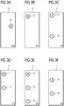
- FIGS. 3A to 3F show possible definitions of the luminous points 11, 12, 13, 14, 15, 16 of the in the FIGS. 2A to 2F Driving terms H, F1, F2, F3, F5, F6 as master points M and slave points S.
- the luminous points 11, 12, 13, 14, 15, 16 are defined as master and slave points that at each driving concept H, F1, F2, F3, F5, F6 exactly one master point M is involved.
- Zero to two slave points S are assigned to this master point M, whereby one slave point may be assigned to several master points.
- the circuit arrangement 1 is designed to operate each of the luminous points 11, 12, 13, 14, 15, 16 of the driving concept H, F1, F2, F3, F5, F6 with the fixed starting impedance, and to switch on each of the slave points S. to register the driving concept and report this to the master point M.
- the fixed starting impedance preferably coincides with an operating point of an incandescent lamp. This has the advantage that the present in the existing interlocking 2, set on the incandescent lamps used, control and monitoring circuit can be used.
- FIG. 4 7 shows a known buck converter 40.
- the buck converter 40 is used for realizing a variable load at the master point M, the slave point S, or generally at one, several or all of the luminous points 11, 12, 13, 14, 15, 16 used.
- a variable load means a variable impedance.
- the impedance can be selected within certain limits, since the duty cycle for the transistor T can not be resolved arbitrarily exactly.
- the buck converter 40 comprises, for example, a switching element T1, an inductance L1 and a fixed load R L.
- the switching element T1 is, for example, a transistor T1, which comprises a connection for a control circuit S.
- T1 conducts: the current flows from the source DC via T1, L1 and RL.
- L1 stores energy.
- the source "sees” the impedance R L.
- T1 blocks: the current flows through D1, L1 and RL.
- L1 gives off energy.
- the ON / OFF time ratio is selected at T1
- the time average of the current taken from the DC source changes.
- the mean value of the load which the source DC "sees” also changes.
- the buck converter 40 was originally designed for DC voltage, but can also be a variable load to AC voltage, for example, by a bridge rectifier is connected upstream.
- a further exemplary embodiment relates to a method for operating the path signal 3 with light-emitting diodes.
- the railway signal 3 can be controlled by a signal box 2.
- the signal box 3 is designed for a light bulb signal.
- a driving concept H, F1, F2, F3, F5, F6 of the path signal 3 comprises a selection of luminous points 11, 12, 13, 14, 15, 16 of the path signal.
- one of the luminous points 11, 12, 13, 14, 15, 16 of one of the driving terms H, F1, F2, F3, F5, F6 is defined as master point M.
- the driving concept H, F1, F2, F3, F5, F6 is turned on by the interlocking 2.
- each of the luminous points 11, 12, 13, 14, 15, 16 of the driving concept H F1, F2, F3, F5, F6 first assumes a fixed electrical starting impedance. Thereafter, the voltage across the master point M is determined. Based on the determined voltage, it is determined with which brightness value the interlocking 2 the Railway signal intended to operate 3. For example, it is determined whether the signal box 2 currently operates the path signal 3 with a day voltage or a night voltage, which is designed for a conventional bulb path signal. The impedance of the master point M is adjusted, so that a light-emitting diode of the master point M is operated with the intention by the interlocking 2 brightness value.
- the other luminous points 11, 12, 13, 14, 15, 16 of the driving concept H, F1, F2, F3, F5, F6 are defined as slave points S.
- the slave points S signal their connection to the master point M.
- the master point M transmits the brightness value to the slave points S.
- the impedance of the equipped with a LED slave points is adjusted so that they are operated with the intended by the interlocking 2 brightness value.
- a master point M is defined for each driving concept H, F1, F2, F3, F5, F6 of the railway signal.
- Each of these master points M can be assigned zero to two slave points S per driving concept.
- the problem of enabling the use of LEDs in train signals even when the interlocking has been designed for the operation of railway signals with incandescent lamps solved by a special master / slave architecture and a method for load distribution. Since in the installed base signal systems "series driving concept circuit" occur for the vein saving, a load distribution logic (load balancing) is required.
- the luminous points are defined as master points M and slave points S, so that exactly one master point M is involved in each driving concept.
- Zero to two slave points S are assigned to this master point, whereby one slave point S may be assigned to several master points.
- the fixed starting impedance must match an operating point of the incandescent lamp in order to adjust the operating conditions for which the system was designed.
- each light spot can monitor itself. If he detects an error, he interrupts the current flow high impedance, which leads to the shutdown of all involved light points. This fault is detected by the interlocking, and automatically "stop" turned on.
- FIG. 5 shows a system 50 that monitors a master point M, a slave point S, or any of the ones in FIG FIG. 1 illustrated luminous points 11, 12, 13, 14, 15, 16 allows. It is an example of monitoring the luminous flux with superposition.
- the system 50 includes a monitoring circuit 54, 55, a in one of the luminous points 11, 12, 13, 14, 15, 16 arranged light-emitting diode 51, a photocell 53, and a signal optics 56th
- the monitoring of a luminous point 11, 12, 13, 14, 15, 16 takes place in a command / message procedure.
- a portion 52 of the light is coupled to a photodiode 53.
- a first monitoring circuit 54 determines whether the luminous spot generates sufficient light and, if appropriate, triggers the switching off of the path signal 3 with the aid of the monitoring circuit 55. By superposing the light of the light-emitting diode 51 with a high-frequency signal, the generated light can be distinguished from the ambient light.
- a method for monitoring a luminous spot 11, 12, 13, 14, 15, 16 operated by means of a light-emitting diode 51 is preceded by a path signal 3.
- light is generated by means of the light-emitting diode 51 by means of a significant drive signal.
- a portion of the light generated by the light-emitting diode 51 is coupled out of the path signal 3 by the signal optics 56 as part of a driving concept H, F1, F2, F3, F5, F6.
- a smaller portion 52 of the light generated by the light emitting diode 51 is coupled to the photodiode 53.
- An electrical output signal generated thereby by the photodiode 53 is input to the monitoring circuit 54.
- the monitoring circuit 54 analyzes the output signal and determines whether the light emitting diode 51 generates enough light.
- the drive signal is sufficiently significant that the portion of the light of the light emitting diode 51 produced by the drive signal is distinguishable in the output signal from the portion of the output signal generated by ambient light.
- the monitoring circuit 54 may isolate the portion of the output signal generated by the light emitting diode 51 from the portion of the output signal generated by ambient light. A sufficient significance of the drive signal can be ensured, for example, by means of a frequency of the drive signal. If by the monitoring circuit 54 it is determined that the luminous point 11, 12, 13, 14, 15, 16 does not generate enough light, the path signal 3 is turned off.
Landscapes
- Engineering & Computer Science (AREA)
- Mechanical Engineering (AREA)
- Train Traffic Observation, Control, And Security (AREA)
Description
Leuchtdioden (LEDs) an Bahnsignalen erhöhen die Verfügbarkeit und reduzieren die Instandhaltungskosten. Das Eisenbahnnetz ist in vielen Ländern im Wesentlichen fertig gebaut, Glühlampen sind weit verbreitet. Sie sollten somit an in Betrieb stehenden Anlagen durch Leuchtdioden ausgetauscht werden können. Die bestehende Ansteuerschaltung, welche einen massgeblichen Teil der Zulassung der Anlage darstellt, soll beibehalten werden können. Die Möglichkeit eines solchen Beibehaltens bezeichnet man als Retrofit.Light-emitting diodes (LEDs) on railway signals increase availability and reduce maintenance costs. The rail network is essentially finished in many countries, incandescent lamps are widely used. They should therefore be able to be replaced by light emitting diodes on systems that are in operation. The existing control circuit, which represents a significant part of the approval of the system, should be able to be maintained. The possibility of such maintenance is called retrofit.
Die besondere Herausforderung bei Haupt- und Vorsignalen besteht in der präzisen Stromüberwachung des Stellwerks sowie der Tatsache, dass die Leuchtpunkte eines Fahrbegriffs als Serieschaltung angeschaltet werden. Weiterhin ist der Sicherheit besondere Beachtung zu schenken, da ein Versagen eines Leuchtpunktes eine unmittelbare Gefährdung eines Zuges zur Folge haben kann.The special challenge with main and presignal signals lies in the precise current monitoring of the interlocking as well as the fact that the luminous points of a driving concept are switched on as series connection. Furthermore, the safety is to pay particular attention, since a failure of a luminous point can have an immediate endangerment of a train result.
Weiterhin muss die Lösung flexibel konfigurierbar sein, da unterschiedlichste Kombinationen von Signalen im Einsatz sind. Das Dokument
Leuchtdioden als Retrofit für Hauptsignale sind bislang nicht verfügbar. LED-basierte Leuchtpunkte bedingen ein spezielles Ansteuerungselement oder eine spezielle Konfiguration der bestehenden Ansteuerung und stehen zurzeit nur für elektronische Stellwerke zur Verfügung, welche von Beginn weg für den Betrieb mit Leuchtdioden konzipiert wurden.Light-emitting diodes as a retrofit for main signals are not yet available. LED-based luminous points require a special control element or a special configuration of the existing control and are currently only available for electronic signal boxes, which were designed from the start for operation with LEDs.
Der vorliegenden Erfindung liegt daher die Aufgabe zugrunde, eine Verwendung von Leuchtdioden in Bahnsignalen auch dann zu ermöglichen, wenn das Stellwerk für den Betrieb von Bahnsignalen mit Glühlampen ausgelegt wurde.The present invention is therefore based on the object, a use of light emitting diodes in train signals then too if the interlocking has been designed for the operation of railway signals with incandescent lamps.
Diese Aufgabe wird durch die durch die unabhängigen Ansprüche beschriebenen Lösungen gelöst.This object is achieved by the solutions described by the independent claims.
Gemäss einem Aspekt wird eine Schaltungsanordnung für ein Bahnsignal vorgestellt. Das Bahnsignal umfasst mehrere Leuchtpunkte. Die Leuchtpunkte bilden in verschiedenen Kombinationen jeweils einen Fahrbegriff. Die Schaltungsanordnung ist ausgestaltet für jeden Fahrbegriff genau einen der Leuchtpunkte als Masterpunkt zu definieren. Zudem ist die Schaltungsanordnung ausgestaltet, den als Masterpunkt definierten Leuchtpunkt eines Fahrbegriffs mit mehr als einer Impedanz zu betreiben. Zudem ist die Schaltungsanordnung ausgestaltet, den Masterpunkt mit einer fixen Startimpedanz zu betreiben und darauf basierend eine Spannung zu ermitteln, mit der welcher der Fahrbegriff aktuell betrieben wird.According to one aspect, a circuit arrangement for a railway signal is presented. The railway signal comprises several luminous points. The luminous dots each form a driving concept in various combinations. The circuit arrangement is designed for each driving concept to define exactly one of the luminous dots as a master point. In addition, the circuit arrangement is designed to operate the luminous point defined as a master point of a driving concept with more than one impedance. In addition, the circuit arrangement is configured to operate the master point with a fixed starting impedance and based on this to determine a voltage with which the driving concept is currently being operated.
Gemäss einem weiteren Aspekt wird ein Verfahren zum Betreiben eines Bahnsignals mit Leuchtdioden vorgestellt. Das Bahnsignal ist durch ein Stellwerk ansteuerbar, welches für ein Glühlampenbahnsignal ausgelegt ist. In einem Verfahrensschritt wird einer der Leuchtpunkte eines Fahrbegriffs als Masterpunkt definiert. Der Fahrbegriff umfasst eine Auswahl der Leuchtpunkte des Bahnsignals. In einem weiteren Verfahrensschritt wird der Fahrbegriff durch das Stellwerk eingeschaltet. Dabei nimmt beim Einschalten des Fahrbegriffs zunächst jeder der Leuchtpunkte des Fahrbegriffs eine fixe elektrische Startimpedanz ein. In einem weiteren Verfahrensschritt wird die Spannung über dem Masterpunkt ermittelt. Anhand der ermittelten Spannung wird ermittelt, mit welchem Helligkeitswert das Stellwerk das Bahnsignal zu betreiben beabsichtigt. In einem weiteren Verfahrensschritt wird die Impedanz des Masterpunktes angepasst, sodass der Masterpunkt mit dem durch das Stellwerk beabsichtigten Helligkeitswert betrieben wird.According to a further aspect, a method for operating a railway signal with light-emitting diodes is presented. The railway signal can be controlled by an interlocking, which is designed for a light bulb signal. In one method step, one of the luminous points of a driving concept is defined as a master point. The driving concept comprises a selection of the luminous points of the railway signal. In a further method step, the driving concept is switched on by the signal box. When switching on the driving concept, each of the luminous points of the driving concept initially assumes a fixed electrical starting impedance. In a further method step, the voltage is determined above the master point. Based on the determined voltage, it is determined with which brightness value the signal box intends to operate the path signal. In a further method step, the impedance of the master point is adjusted so that the master point is operated with the brightness value intended by the interlocking.
Vorteilhafte Ausgestaltungen der Erfindung sind in weiteren Ansprüchen ange¬geben.Advantageous embodiments of the invention are specified in further claims.
Ausführungsbeispiele der Erfindung werden nachfolgend anhand der Figuren beispielsweise näher erläutert. Dabei zeigen:
-
Figur 1 ein Blockdiagramm einer Bahninfrastruktur welche ein Bahnsignal umfasst gemäss einem bevorzugten Ausführungsbeispiel der Erfindung; -
Figuren 2A bis 2F jeweils einen unterschiedlichen Fahrbegriff des Bahnsignals vonFigur 1 (gemäss den Schweizerischen Fahrdienstvorschriften) ; -
Figuren 3A bis 3F jeweils eine mögliche Definition von Masterpunkten und Slavepunkten der inFiguren 2A - 2F dargestellten Fahrbegriffe; -
Figur 4 -
Figur 5 ein Blockdiagramm eines Systems, welches ausgestaltet ist, einen mittels einer Leuchtdiode betriebenen Leuchtpunkt eines Bahnsignals zu überwachen.
-
FIG. 1 a block diagram of a railway infrastructure which comprises a railway signal according to a preferred embodiment of the invention; -
FIGS. 2A to 2F each a different driving concept of the railway signal ofFIG. 1 (according to the Swiss driving regulations); -
FIGS. 3A to 3F one possible definition of master points and slave points of inFIGS. 2A-2F illustrated driving concepts; -
FIG. 4 a block diagram of a circuit with which a variable impedance can be generated; -
FIG. 5 a block diagram of a system which is configured to monitor a operated by means of a light emitting diode luminous spot of a railway signal.
Die
Mit Verweis zurück auf
Damit anstelle von Glühlampen die Leuchtpunkte 11, 12, 13, 14, 15, 16 trotzdem mit Leuchtdioden betrieben werden können, umfasst das Bahnsignal 3 die Schaltungsanordnung 1.So that instead of incandescent lamps the
Die Schaltungsanordnung 1 ist so ausgestaltet, dass sie durch das als abgesetzte Einheit ausgestaltete Stellwerk 2 betreibbar ist, und die Fahrbegriffe H, F1, F2, F3, F5, F6 jeweils durch eine serielle Schaltung der zum Fahrbegriff H, F1, F2, F3, F5, F6 gehörenden Leuchtpunkte 11, 12, 13, 14, 15, 16 einschalten kann. Dazu ist die Schaltungsanordnung 1 ausgestaltet, für jeden Fahrbegriff H, F1, F2, F3, F5, F6 genau einen der Leuchtpunkte 11, 12, 13, 14, 15, 16 als Masterpunkt M zu betreiben. Zudem ist die Schaltungsanordnung 1 ausgestaltet, den somit als Masterpunkt M definierten Leuchtpunkt 11, 12, 13, 14, 15, 16 dieses Fahrbegriffs mit mehr als einer Impedanz zu betreiben. Zudem ist die Schaltungsanordnung 1 ausgestaltet, den Masterpunkt M mit einer fixen Startimpedanz zu betreiben und darauf basierend eine Spannung zu ermitteln, mit welcher der Fahrbegriff H, F1, F2, F3, F5, F6 aktuell betrieben wird. Vorzugsweise ist dabei die Schaltungsanordnung 1 ausgestaltet, anhand der ermittelten Spannung zu erkennen, ob das Stellwerk 2 den Fahrbegriff H, F1, F2, F3, F5, F6 aktuell mit einer Tagspannung oder einer Nachtspannung betreibt. Die ermittelte Spannung repräsentiert einen gewünschten Helligkeitswert, der sich ergäbe, wenn das Stellwerk ein herkömmliches mit Glühlampen betriebenes Bahnsignal antreiben würde. Um eine durch den Masterpunkt M betriebene Leuchtdiode mit dem gewünschten Helligkeitswert zu betreiben, ist die Schaltungsanordnung 1 ausgestaltet anhand der ermittelten Spannung die Impedanz des Masterpunktes M so einzustellen, dass die Leuchtdiode des Masterpunktes M mit dem gewünschten Helligkeitswert betrieben wird.The circuit arrangement 1 is designed so that it can be operated by the offset unit configured as the
Vorzugsweise ist die Schaltungsanordnung 1 ausgestaltet, diejenigen Leuchtpunkte 11, 12, 13, 14, 15, 16 eines Fahrbegriffs H, F1, F2, F3, F5, F6, die nicht Masterpunkt M sind, als Slavepunkte S zu betreiben. In den in den
Vorzugsweise wird der Masterpunkt M eines, mehrere oder aller Fahrbegriffe durch die Schaltungsanordnung 1 umfasst. Vorzugsweise werden die Slavepunkte S durch die Schaltungsanordnung 1 umfasst. Vorzugsweise werden die Leuchtpunkte 11, 12, 13, 14, 15, 16 durch die Schaltungsanordnung 1 umfasst.Preferably, the master point M is one, several or all driving terms covered by the circuit arrangement 1. Preferably, the slave points S by the circuit arrangement 1 includes. Preferably, the
Gemäss einer Ausführungsform ist die Schaltungsanordnung 1 ausgestaltet, jeden der Leuchtpunkte 11, 12, 13, 14, 15, 16 des Fahrbegriffs H, F1, F2, F3, F5, F6 mit der fixen Startimpedanz zu betreiben, und die Einschaltung jedes der Slavepunkte S des Fahrbegriffs zu registrieren und dies dem Masterpunkt M zu melden. Vorzugsweise stimmt die fixe Startimpedanz mit einem Betriebspunkt einer Glühlampe überein. Dies hat den Vorteil, dass die im bestehenden Stellwerk 2 vorhandene, auf die verwendeten Glühlampen eingestellte, Ansteuer- und Überwachungsschaltung weiter verwendet werden kann.According to one embodiment, the circuit arrangement 1 is designed to operate each of the
Beim Tiefsetzsteller 40 handelt es sich um eine klassische Schaltung aus der Leistungselektronik. Sie wird eingesetzt, um eine höhere Spannung in eine kleinere umzusetzen. Wird sie mit einer fixen Last RL betrieben (RL = constant), stellt sie eingangsseitig eine variable Last dar.The
Es gibt zwei Betriebszustände:
1. T1 leitet: der Strom fliesst von der Quelle DC über T1, L1 und RL. L1 speichert Energie. Die Quelle «sieht» die Impedanz RL. 2. T1 sperrt: der Strom fliesst über D1, L1 und RL. L1 gibt Energie ab. Die Quelle DC «sieht» keine Last.There are two operating states:
1. T1 conducts: the current flows from the source DC via T1, L1 and RL. L1 stores energy. The source "sees" the
Abhängig davon, wie das Verhältnis Einschalt-/Sperrzeit bei T1 gewählt wird, ändert sich der zeitliche Mittelwert des Stromes, welcher der Quelle DC entnommen wird. Somit ändert auch der Mittelwert der Last, welche die Quelle DC «sieht».Depending on how the ON / OFF time ratio is selected at T1, the time average of the current taken from the DC source changes. Thus, the mean value of the load which the source DC "sees" also changes.
Der Tiefsetzsteller 40 wurde ursprünglich für Gleichspannung entworfen, kann jedoch auch an Wechselspannung eine variable Last darstellen, indem beispielsweise ein Brückengleichrichter vorgeschaltet wird.The
Ein weiteres Ausführungsbeispiel betrifft ein Verfahren zum Betreiben des Bahnsignals 3 mit Leuchtdioden. Das Bahnsignal 3 ist durch ein Stellwerk 2 ansteuerbar. Das Stellwerk 3 ist für ein Glühlampenbahnsignal ausgelegt. Ein Fahrbegriff H, F1, F2, F3, F5, F6 des Bahnsignals 3 umfasst eine Auswahl von Leuchtpunkten 11, 12, 13, 14, 15, 16 des Bahnsignals. Um das Verfahren durchzuführen wird einer der Leuchtpunkte 11, 12, 13, 14, 15, 16 eines der Fahrbegriffe H, F1, F2, F3, F5, F6 als Masterpunkt M definiert. Der Fahrbegriff H, F1, F2, F3, F5, F6 wird durch das Stellwerk 2 eingeschaltet. Beim Einschalten des Fahrbegriffs H, F1, F2, F3, F5, F6 nimmt zunächst jeder der Leuchtpunkte 11, 12, 13, 14, 15, 16 des Fahrbegriffs H, F1, F2, F3, F5, F6 eine fixe elektrische Startimpedanz ein. Danach wird die Spannung über dem Masterpunkt M ermittelt. Anhand der ermittelten Spannung, wird ermittelt, mit welchem Helligkeitswert das Stellwerk 2 das Bahnsignal 3 zu betreiben beabsichtigt. Beispielsweise wird ermittelt, ob das Stellwerk 2 das Bahnsignal 3 aktuell mit einer Tagspannung oder einer Nachtspannung betreibt, welche für ein herkömmliches Glühlampenbahnsignal ausgelegt ist. Die Impedanz des Masterpunktes M wird angepasst, sodass eine Leuchtdiode des Masterpunktes M mit dem durch das Stellwerk 2 beabsichtigten Helligkeitswert betrieben wird.A further exemplary embodiment relates to a method for operating the path signal 3 with light-emitting diodes. The
Zudem werden die anderen Leuchtpunkte 11, 12, 13, 14, 15, 16 des Fahrbegriffs H, F1, F2, F3, F5, F6 als Slavepunkte S definiert. Die Slavepunkte S melden ihre Einschaltung an den Masterpunkt M. Der Masterpunkt M übermittelt den Helligkeitswert an die Slavepunkte S. Die Impedanz der mit einer Leuchtdiode bestückten Slavepunkte wird angepasst, sodass diese mit dem durch das Stellwerk 2 beabsichtigten Helligkeitswert betrieben werden.In addition, the other
Vorzugsweise wird für jeden Fahrbegriff H, F1, F2, F3, F5, F6 des Bahnsignals ein Masterpunkt M festgelegt. Jedem dieser Masterpunkte M können pro Fahrbegriff null bis zwei Slavepunkte S zugeordnet sein.Preferably, a master point M is defined for each driving concept H, F1, F2, F3, F5, F6 of the railway signal. Each of these master points M can be assigned zero to two slave points S per driving concept.
Gemäss bevorzugten Ausführungsbeispielen wird das Problem, eine Verwendung von Leuchtdioden in Bahnsignalen auch dann zu ermöglichen, wenn das Stellwerk für den Betrieb von Bahnsignalen mit Glühlampen ausgelegt wurde, durch eine spezielle Master / Slave Architektur sowie ein Verfahren zur Lastverteilung gelöst. Da in der installierten Basis Signalsysteme "Serie- Fahrbegriffsschaltung" für die Adereinsparung vorkommen, wird eine Lastverteilungslogik (Last- Symmetrierung) benötigt.According to preferred embodiments, the problem of enabling the use of LEDs in train signals even when the interlocking has been designed for the operation of railway signals with incandescent lamps, solved by a special master / slave architecture and a method for load distribution. Since in the installed base signal systems "series driving concept circuit" occur for the vein saving, a load distribution logic (load balancing) is required.
An jedem Bahnsignal 3 werden die Leuchtpunkte so als Masterpunkte M und Slavepunkte S definiert, dass an jedem Fahrbegriff genau ein Masterpunkt M beteiligt ist. Diesem Masterpunkt sind null bis zwei Slavepunkte S zugeordnet, wobei ein Slavepunkt S mehreren Masterpunkten zugeordnet sein darf.At each path signal 3, the luminous points are defined as master points M and slave points S, so that exactly one master point M is involved in each driving concept. Zero to two slave points S are assigned to this master point, whereby one slave point S may be assigned to several master points.
Wird ein Fahrbegriff durch das Stellwerk eingeschaltet, nimmt zunächst jeder Leuchtpunkt eine fixe elektrische Startimpedanz ein (Beispiel von 75 Ohm bei 40V Glühlampen). Die Slavepunkte melden die Einschaltung ihren Masterpunkten. Dem Masterpunkt ist somit bekannt:
- welche Spannung an ihm selbst anliegt
- die Anzahl der eingeschalteten Leuchtpunkte.
- which tension is attached to itself
- the number of illuminated dots.
Die fixe Startimpedanz muss dabei mit einem Betriebspunkt der Glühlampe übereinstimmen, damit sich die Betriebsverhältnisse einstellen, für die das System ausgelegt wurde.The fixed starting impedance must match an operating point of the incandescent lamp in order to adjust the operating conditions for which the system was designed.
Nun bestimmt der Masterpunkt, ob die Leuchtpunkte mit Tagspannung oder Nachtspannung angeschaltet wurden. Anschliessend teilt er den Slavepunkten die einzustellende Helligkeit mit (Tag / Nacht), sowie die Impedanz welche sie einnehmen sollen. Damit werden die Betriebspunkte der Glühlampe nachgebildet und die Ansteuerungselektronik (=Stellteil) kann beibehalten werden.Now, the master point determines whether the light points were switched on with day voltage or night voltage. Then he tells the slave points the brightness to be set (day / night), as well as the impedance which they should take. Thus, the operating points of the incandescent lamp are simulated and the control electronics (= control part) can be maintained.
Da die Leuchtpunkte in Serie geschaltet werden, kann sich jeder Leuchtpunkt selbst überwachen. Stellt er einen Fehler fest, unterbricht er den Stromfluss hochohmig, was zur Abschaltung aller beteiligten Leuchtpunkte führt. Dieser Fehlerfall wird durch das Stellwerk detektiert, und automatisch "Halt" angeschaltet.Since the light dots are connected in series, each light spot can monitor itself. If he detects an error, he interrupts the current flow high impedance, which leads to the shutdown of all involved light points. This fault is detected by the interlocking, and automatically "stop" turned on.
Die Überwachung eines Leuchtpunktes 11, 12, 13, 14, 15, 16 erfolgt in einem Kommando/Meldeverfahren. Es wird ein Teil 52 des Lichtes auf eine Fotodiode 53 ausgekoppelt. Eine erste Überwachungsschaltung 54 stellt fest, ob der Leuchtpunkt genügend Licht erzeugt und löst gegebenenfalls mit Hilfe der Überwachungsschaltung 55 die Abschaltung des Bahnsignals 3 aus. Indem das Licht der Leuchtdiode 51 mit einem hochfrequenten Signal überlagert wird, kann das erzeugte Licht vom Umgebungslicht unterschieden werden.The monitoring of a
Gemäss einem Beispiel, das nicht Teil der beanspruchten Erfindung ist, wird ein Verfahren zur Überwachung eines mittels einer Leuchtdiode 51 betriebenen Leuchtpunktes 11, 12, 13, 14, 15, 16 eines Bahnsignals 3 vorgeschaltet. In einem Verfahrensschritt wird Licht mittels der Leuchtdiode 51 mittels eines Signifikanten Ansteuersignals erzeugt. Ein Teil des durch die Leuchtdiode 51 erzeugten Lichts wird durch die Signaloptik 56 als Teil eines Fahrbegriffs H, F1, F2, F3, F5, F6 aus dem Bahnsignal 3 ausgekoppelt. Ein kleinerer Teil 52 des durch die Leuchtdiode 51 erzeugten Lichts wird auf die Fotodiode 53 ausgekoppelt.According to an example which is not part of the claimed invention, a method for monitoring a
Ein dadurch durch die Fotodiode 53 erzeugtes elektrisches Ausgangssignal wird in die Überwachungsschaltung 54 eingespeist. Die Überwachungsschaltung 54 analysiert das Ausgangssignal und stellt fest, ob die Leuchtdiode 51 genügend Licht erzeugt. Das Ansteuersignal ist ausreichend signifikant, dass der durch das Ansteuersignal erzeugte Teil des Lichts der Leuchtdiode 51 in dem Ausgangssignal von dem durch Umgebungslicht erzeugten Anteil des Ausgangssignals unterscheidbar ist. Die Überwachungsschaltung 54 kann den durch die Leuchtdiode 51 erzeugten Anteil des Ausganssignals von dem durch Umgebungslicht erzeugten Anteil des Ausgangssignals isolieren. Eine ausreichende Signifikanz des Ansteuersignals kann beispielsweise mittels einer Frequenz des Ansteuersignals sichergestellt werden. Falls durch die Überwachungsschaltung 54 festgestellt wird, dass der Leuchtpunkt 11, 12, 13, 14, 15, 16 nicht genügend Licht erzeugt, wird das Bahnsignal 3 ausgeschaltet. An electrical output signal generated thereby by the
Claims (11)
- Circuit arrangement (1) for a railway signal (3) comprising a plurality of LED luminous spots (11, 12, 13, 14, 15, 16) which in various combinations in each case form a proceed aspect (H, F1, F2, F3, F5, F6), wherein the circuit arrangement (1) is configured such that:a) the circuit arrangement can be operated by an interlocking (2) configured as a remote unit and the proceed aspects (H, F1, F2, F3, F5, F6) are in each case activated by a serial switching of the LED luminous spots (11, 12, 13, 14, 15, 16) belonging to the proceed aspect (H, F1, F2, F3, F5, F6),b) the circuit arrangement for each proceed aspect (H, F1, F2, F3, F5, F6) operates precisely one of the LED luminous spots (11, 12, 13, 14, 15, 16) provided for this proceed aspect as a master point (M) with an adjustable impedance;c) the circuit arrangement operates the master point (M) with a fixed starting impedance and based on this determines a voltage with which the proceed aspect (H, F1, F2, F3, F5, F6) currently specified by the interlocking (2) is to be operated, wherein based on the determined voltage the circuit arrangement adjusts the impedance of the master point (M) such that the LED luminous spot of the master point (M) can be operated with a brightness value corresponding to the determined voltage;
andd) at least one further LED luminous spot (11, 12, 13, 14, 15, 16) of the proceed aspect operated with a specified starting impedance can be controlled as a slave point (S) by the circuit arrangement such that the circuit arrangement transmits to the slave point (S) the determined voltage and an impedance value with which the slave point (S) should be operated. - Circuit arrangement (1) according to claim 1, wherein the determination of the voltage comprises being able to determine whether the proceed aspect (H, F1, F2, F3, F5, F6) should currently be operated with a day voltage or a night voltage.
- Circuit arrangement (1) according to one of the preceding claims, wherein each of the LED luminous spots (11, 12, 13, 14, 15, 16) of a proceed aspect (H, F1, F2, F3, F5, F6) can be operated with the fixed starting impedance, and the activation of each of the slave points (S) can be notified to the master point (M).
- Circuit arrangement (1) according to one of the preceding claims, wherein the fixed starting impedance coincides with an operating point of an incandescent lamp.
- Circuit arrangement (1) according to one of the preceding claims, wherein each master point (M) is assigned zero to two slave points (S).
- Circuit arrangement (1) according to one of the preceding claims, wherein the circuit arrangement (1) comprises a load distribution logic.
- Railway signal (3), comprising a circuit arrangement (1) and LED luminous spots (11, 12, 13, 14, 15, 16) according to one of the preceding claims.
- Method for operating a railway signal (3) with LED luminous spots, wherein the railway signal (3) can be controlled by an interlocking (2) which is designed for an incandescent lamp railway signal, wherein a proceed aspect (H, F1, F2, F3, F5, F6) of the railway signal (3) comprises a selection of serially switched LED luminous spots (11, 12, 13, 14, 15, 16) of the railway signal, comprising the following method steps:- definition of one of the LED luminous spots (11, 12, 13, 14, 15, 16) of the proceed aspect (H, F1, F2, F3, F5, F6) as a master point (M);- activation of the proceed aspect (H, F1, F2, F3, F5, F6) by the interlocking (2), wherein when activating the proceed aspect (H, F1, F2, F3, F5, F6) initially each of the LED luminous spots (11, 12 , 13, 14, 15, 16) of the proceed aspect (H, F1, F2, F3, F5, F6) assumes a fixed electrical starting impedance;- determination of the voltage across the master point (M) and determination based on the determined voltage of the brightness value with which the interlocking intends to operate the railway signal;- adjustment of the impedance of the master point (M), such that the master point (M) is operated with the brightness value intended by the interlocking (2); and- definition of the one or of the other LED luminous spots (11, 12, 13, 14, 15, 16) of the proceed aspect (H, F1, F2, F3, F5, F6) as slave points (S);- notification of the activation of the one or more slave points (S) to the master point (M);- transmission of the brightness value by the master point (M) to the one or more slave points (S);- adjustment of the impedance of the one or more slave points (S), such that the one or more slave points (S) are operated with the brightness value intended by the interlocking (2).
- Method according to claim 8, wherein the determination of the voltage across the master point (M) comprises determining whether the interlocking (2) is currently operating the railway signal (3) with a day voltage or a night voltage.
- Method according to claim 8 or 9, wherein the fixed starting impedance coincides with an operating point of an incandescent lamp.
- Method according to one of claims 8 to 10, wherein for each proceed aspect (H, F1, F2, F3, F5, F6) of the railway signal, a master point (M) is set, to which a selection of zero to two slave points (S) is assigned.
Priority Applications (1)
| Application Number | Priority Date | Filing Date | Title |
|---|---|---|---|
| EP14151166.7A EP2894389B1 (en) | 2014-01-14 | 2014-01-14 | Replacement of incandescent lamps railway signals by light emitting diodes |
Applications Claiming Priority (1)
| Application Number | Priority Date | Filing Date | Title |
|---|---|---|---|
| EP14151166.7A EP2894389B1 (en) | 2014-01-14 | 2014-01-14 | Replacement of incandescent lamps railway signals by light emitting diodes |
Publications (2)
| Publication Number | Publication Date |
|---|---|
| EP2894389A1 EP2894389A1 (en) | 2015-07-15 |
| EP2894389B1 true EP2894389B1 (en) | 2019-10-23 |
Family
ID=49989533
Family Applications (1)
| Application Number | Title | Priority Date | Filing Date |
|---|---|---|---|
| EP14151166.7A Active EP2894389B1 (en) | 2014-01-14 | 2014-01-14 | Replacement of incandescent lamps railway signals by light emitting diodes |
Country Status (1)
| Country | Link |
|---|---|
| EP (1) | EP2894389B1 (en) |
Family Cites Families (3)
| Publication number | Priority date | Publication date | Assignee | Title |
|---|---|---|---|---|
| DE59406833D1 (en) * | 1993-11-05 | 1998-10-08 | Siemens Schweiz Ag | CIRCUIT ARRANGEMENT FOR RAILWAY LIGHT SIGNALING SYSTEMS |
| DE10221573B4 (en) * | 2002-05-08 | 2004-03-18 | Siemens Ag | Circuit arrangement for operating a light sign |
| EP2463174B1 (en) * | 2010-12-09 | 2013-10-30 | Siemens Schweiz AG | Method and device for replacing a bulb of a light signal |
-
2014
- 2014-01-14 EP EP14151166.7A patent/EP2894389B1/en active Active
Non-Patent Citations (1)
| Title |
|---|
| None * |
Also Published As
| Publication number | Publication date |
|---|---|
| EP2894389A1 (en) | 2015-07-15 |
Similar Documents
| Publication | Publication Date | Title |
|---|---|---|
| WO2001091521A1 (en) | Traffic signal installation comprising an led-light source | |
| EP1992542B2 (en) | LED arrangement for light signal emitter for railway level-crossings, light signal emitter for railway level-crossings with such an LED arrangement and method of operating the LED arrangement | |
| DE102004002026A1 (en) | Control of lamp operating devices via a modulated DC bus | |
| DE112011105504T5 (en) | LED lighting device | |
| DE102010030520A1 (en) | Work light for a commercial vehicle, in particular industrial truck | |
| EP2687418B1 (en) | LED track signal for rail transport and interface for such an LED track signal | |
| EP2894389B1 (en) | Replacement of incandescent lamps railway signals by light emitting diodes | |
| DE102008029725A1 (en) | signaler | |
| EP2182778B1 (en) | Method for controlling an external light and corresponding lamps | |
| EP3235349B1 (en) | Brightness control for a light signal system | |
| DE112011100717B4 (en) | Operating device for lamps and bus system and method for operating a control gear | |
| DE10206649A1 (en) | display device | |
| EP2866524A2 (en) | Assembly and method for monitoring a plurality of LED strings and LED lamp with such an assembly | |
| EP3934384B1 (en) | Arrangement for driving leds | |
| DE10358993B4 (en) | Light signal transmitter and traffic signal system with a light signal transmitter | |
| DE102011001549B4 (en) | Arrangement and method for controlling and monitoring the exterior lighting of rail vehicles | |
| DE102013108689B3 (en) | Circuit for controlling the power consumption of an LED unit and LED light with such a LED unit | |
| EP2564488A2 (en) | Power supply unit for signal luminaires having energy sources having separate grounds | |
| DE202010016339U1 (en) | circuitry | |
| DE102012019861B4 (en) | Method for operating a signal transmitter and signal transmitter | |
| EP2979955B1 (en) | Led unit for light signal transmitter and light signal emitter with such a unit | |
| WO2012126895A2 (en) | Led signaling device, and method for operating such a signaling device | |
| EP2691266B1 (en) | Rail vehicle light module | |
| DE102010048285B4 (en) | Illumination arrangement in underground mining and method for controlling an underground lighting | |
| EP3307023A1 (en) | Operating device for light with output of status information in particular for fault analysis |
Legal Events
| Date | Code | Title | Description |
|---|---|---|---|
| PUAI | Public reference made under article 153(3) epc to a published international application that has entered the european phase |
Free format text: ORIGINAL CODE: 0009012 |
|
| 17P | Request for examination filed |
Effective date: 20140114 |
|
| AK | Designated contracting states |
Kind code of ref document: A1 Designated state(s): AL AT BE BG CH CY CZ DE DK EE ES FI FR GB GR HR HU IE IS IT LI LT LU LV MC MK MT NL NO PL PT RO RS SE SI SK SM TR |
|
| AX | Request for extension of the european patent |
Extension state: BA ME |
|
| R17P | Request for examination filed (corrected) |
Effective date: 20160107 |
|
| RBV | Designated contracting states (corrected) |
Designated state(s): AL AT BE BG CH CY CZ DE DK EE ES FI FR GB GR HR HU IE IS IT LI LT LU LV MC MK MT NL NO PL PT RO RS SE SI SK SM TR |
|
| STAA | Information on the status of an ep patent application or granted ep patent |
Free format text: STATUS: EXAMINATION IS IN PROGRESS |
|
| 17Q | First examination report despatched |
Effective date: 20180327 |
|
| RAP1 | Party data changed (applicant data changed or rights of an application transferred) |
Owner name: SIEMENS MOBILITY AG |
|
| GRAP | Despatch of communication of intention to grant a patent |
Free format text: ORIGINAL CODE: EPIDOSNIGR1 |
|
| STAA | Information on the status of an ep patent application or granted ep patent |
Free format text: STATUS: GRANT OF PATENT IS INTENDED |
|
| INTG | Intention to grant announced |
Effective date: 20190716 |
|
| GRAS | Grant fee paid |
Free format text: ORIGINAL CODE: EPIDOSNIGR3 |
|
| GRAA | (expected) grant |
Free format text: ORIGINAL CODE: 0009210 |
|
| STAA | Information on the status of an ep patent application or granted ep patent |
Free format text: STATUS: THE PATENT HAS BEEN GRANTED |
|
| AK | Designated contracting states |
Kind code of ref document: B1 Designated state(s): AL AT BE BG CH CY CZ DE DK EE ES FI FR GB GR HR HU IE IS IT LI LT LU LV MC MK MT NL NO PL PT RO RS SE SI SK SM TR |
|
| REG | Reference to a national code |
Ref country code: GB Ref legal event code: FG4D Free format text: NOT ENGLISH |
|
| REG | Reference to a national code |
Ref country code: CH Ref legal event code: EP Ref country code: CH Ref legal event code: NV Representative=s name: SIEMENS SCHWEIZ AG, CH |
|
| REG | Reference to a national code |
Ref country code: IE Ref legal event code: FG4D Free format text: LANGUAGE OF EP DOCUMENT: GERMAN |
|
| REG | Reference to a national code |
Ref country code: DE Ref legal event code: R096 Ref document number: 502014012889 Country of ref document: DE |
|
| REG | Reference to a national code |
Ref country code: AT Ref legal event code: REF Ref document number: 1194044 Country of ref document: AT Kind code of ref document: T Effective date: 20191115 |
|
| REG | Reference to a national code |
Ref country code: NL Ref legal event code: MP Effective date: 20191023 |
|
| REG | Reference to a national code |
Ref country code: LT Ref legal event code: MG4D |
|
| PG25 | Lapsed in a contracting state [announced via postgrant information from national office to epo] |
Ref country code: ES Free format text: LAPSE BECAUSE OF FAILURE TO SUBMIT A TRANSLATION OF THE DESCRIPTION OR TO PAY THE FEE WITHIN THE PRESCRIBED TIME-LIMIT Effective date: 20191023 Ref country code: SE Free format text: LAPSE BECAUSE OF FAILURE TO SUBMIT A TRANSLATION OF THE DESCRIPTION OR TO PAY THE FEE WITHIN THE PRESCRIBED TIME-LIMIT Effective date: 20191023 Ref country code: LV Free format text: LAPSE BECAUSE OF FAILURE TO SUBMIT A TRANSLATION OF THE DESCRIPTION OR TO PAY THE FEE WITHIN THE PRESCRIBED TIME-LIMIT Effective date: 20191023 Ref country code: PT Free format text: LAPSE BECAUSE OF FAILURE TO SUBMIT A TRANSLATION OF THE DESCRIPTION OR TO PAY THE FEE WITHIN THE PRESCRIBED TIME-LIMIT Effective date: 20200224 Ref country code: FI Free format text: LAPSE BECAUSE OF FAILURE TO SUBMIT A TRANSLATION OF THE DESCRIPTION OR TO PAY THE FEE WITHIN THE PRESCRIBED TIME-LIMIT Effective date: 20191023 Ref country code: BG Free format text: LAPSE BECAUSE OF FAILURE TO SUBMIT A TRANSLATION OF THE DESCRIPTION OR TO PAY THE FEE WITHIN THE PRESCRIBED TIME-LIMIT Effective date: 20200123 Ref country code: PL Free format text: LAPSE BECAUSE OF FAILURE TO SUBMIT A TRANSLATION OF THE DESCRIPTION OR TO PAY THE FEE WITHIN THE PRESCRIBED TIME-LIMIT Effective date: 20191023 Ref country code: GR Free format text: LAPSE BECAUSE OF FAILURE TO SUBMIT A TRANSLATION OF THE DESCRIPTION OR TO PAY THE FEE WITHIN THE PRESCRIBED TIME-LIMIT Effective date: 20200124 Ref country code: NO Free format text: LAPSE BECAUSE OF FAILURE TO SUBMIT A TRANSLATION OF THE DESCRIPTION OR TO PAY THE FEE WITHIN THE PRESCRIBED TIME-LIMIT Effective date: 20200123 Ref country code: NL Free format text: LAPSE BECAUSE OF FAILURE TO SUBMIT A TRANSLATION OF THE DESCRIPTION OR TO PAY THE FEE WITHIN THE PRESCRIBED TIME-LIMIT Effective date: 20191023 Ref country code: LT Free format text: LAPSE BECAUSE OF FAILURE TO SUBMIT A TRANSLATION OF THE DESCRIPTION OR TO PAY THE FEE WITHIN THE PRESCRIBED TIME-LIMIT Effective date: 20191023 |
|
| PG25 | Lapsed in a contracting state [announced via postgrant information from national office to epo] |
Ref country code: HR Free format text: LAPSE BECAUSE OF FAILURE TO SUBMIT A TRANSLATION OF THE DESCRIPTION OR TO PAY THE FEE WITHIN THE PRESCRIBED TIME-LIMIT Effective date: 20191023 Ref country code: RS Free format text: LAPSE BECAUSE OF FAILURE TO SUBMIT A TRANSLATION OF THE DESCRIPTION OR TO PAY THE FEE WITHIN THE PRESCRIBED TIME-LIMIT Effective date: 20191023 Ref country code: IS Free format text: LAPSE BECAUSE OF FAILURE TO SUBMIT A TRANSLATION OF THE DESCRIPTION OR TO PAY THE FEE WITHIN THE PRESCRIBED TIME-LIMIT Effective date: 20200224 |
|
| PG25 | Lapsed in a contracting state [announced via postgrant information from national office to epo] |
Ref country code: AL Free format text: LAPSE BECAUSE OF FAILURE TO SUBMIT A TRANSLATION OF THE DESCRIPTION OR TO PAY THE FEE WITHIN THE PRESCRIBED TIME-LIMIT Effective date: 20191023 |
|
| REG | Reference to a national code |
Ref country code: DE Ref legal event code: R097 Ref document number: 502014012889 Country of ref document: DE |
|
| PG2D | Information on lapse in contracting state deleted |
Ref country code: IS |
|
| PG25 | Lapsed in a contracting state [announced via postgrant information from national office to epo] |
Ref country code: CZ Free format text: LAPSE BECAUSE OF FAILURE TO SUBMIT A TRANSLATION OF THE DESCRIPTION OR TO PAY THE FEE WITHIN THE PRESCRIBED TIME-LIMIT Effective date: 20191023 Ref country code: EE Free format text: LAPSE BECAUSE OF FAILURE TO SUBMIT A TRANSLATION OF THE DESCRIPTION OR TO PAY THE FEE WITHIN THE PRESCRIBED TIME-LIMIT Effective date: 20191023 Ref country code: RO Free format text: LAPSE BECAUSE OF FAILURE TO SUBMIT A TRANSLATION OF THE DESCRIPTION OR TO PAY THE FEE WITHIN THE PRESCRIBED TIME-LIMIT Effective date: 20191023 Ref country code: DK Free format text: LAPSE BECAUSE OF FAILURE TO SUBMIT A TRANSLATION OF THE DESCRIPTION OR TO PAY THE FEE WITHIN THE PRESCRIBED TIME-LIMIT Effective date: 20191023 Ref country code: IS Free format text: LAPSE BECAUSE OF FAILURE TO SUBMIT A TRANSLATION OF THE DESCRIPTION OR TO PAY THE FEE WITHIN THE PRESCRIBED TIME-LIMIT Effective date: 20200223 |
|
| PLBE | No opposition filed within time limit |
Free format text: ORIGINAL CODE: 0009261 |
|
| STAA | Information on the status of an ep patent application or granted ep patent |
Free format text: STATUS: NO OPPOSITION FILED WITHIN TIME LIMIT |
|
| PG25 | Lapsed in a contracting state [announced via postgrant information from national office to epo] |
Ref country code: SM Free format text: LAPSE BECAUSE OF FAILURE TO SUBMIT A TRANSLATION OF THE DESCRIPTION OR TO PAY THE FEE WITHIN THE PRESCRIBED TIME-LIMIT Effective date: 20191023 Ref country code: IT Free format text: LAPSE BECAUSE OF FAILURE TO SUBMIT A TRANSLATION OF THE DESCRIPTION OR TO PAY THE FEE WITHIN THE PRESCRIBED TIME-LIMIT Effective date: 20191023 Ref country code: MC Free format text: LAPSE BECAUSE OF FAILURE TO SUBMIT A TRANSLATION OF THE DESCRIPTION OR TO PAY THE FEE WITHIN THE PRESCRIBED TIME-LIMIT Effective date: 20191023 Ref country code: SK Free format text: LAPSE BECAUSE OF FAILURE TO SUBMIT A TRANSLATION OF THE DESCRIPTION OR TO PAY THE FEE WITHIN THE PRESCRIBED TIME-LIMIT Effective date: 20191023 |
|
| GBPC | Gb: european patent ceased through non-payment of renewal fee |
Effective date: 20200123 |
|
| 26N | No opposition filed |
Effective date: 20200724 |
|
| REG | Reference to a national code |
Ref country code: BE Ref legal event code: MM Effective date: 20200131 |
|
| PG25 | Lapsed in a contracting state [announced via postgrant information from national office to epo] |
Ref country code: GB Free format text: LAPSE BECAUSE OF NON-PAYMENT OF DUE FEES Effective date: 20200123 Ref country code: LU Free format text: LAPSE BECAUSE OF NON-PAYMENT OF DUE FEES Effective date: 20200114 Ref country code: FR Free format text: LAPSE BECAUSE OF NON-PAYMENT OF DUE FEES Effective date: 20200131 |
|
| PG25 | Lapsed in a contracting state [announced via postgrant information from national office to epo] |
Ref country code: SI Free format text: LAPSE BECAUSE OF FAILURE TO SUBMIT A TRANSLATION OF THE DESCRIPTION OR TO PAY THE FEE WITHIN THE PRESCRIBED TIME-LIMIT Effective date: 20191023 Ref country code: BE Free format text: LAPSE BECAUSE OF NON-PAYMENT OF DUE FEES Effective date: 20200131 |
|
| PG25 | Lapsed in a contracting state [announced via postgrant information from national office to epo] |
Ref country code: IE Free format text: LAPSE BECAUSE OF NON-PAYMENT OF DUE FEES Effective date: 20200114 |
|
| PGFP | Annual fee paid to national office [announced via postgrant information from national office to epo] |
Ref country code: DE Payment date: 20220318 Year of fee payment: 9 |
|
| PG25 | Lapsed in a contracting state [announced via postgrant information from national office to epo] |
Ref country code: TR Free format text: LAPSE BECAUSE OF FAILURE TO SUBMIT A TRANSLATION OF THE DESCRIPTION OR TO PAY THE FEE WITHIN THE PRESCRIBED TIME-LIMIT Effective date: 20191023 Ref country code: MT Free format text: LAPSE BECAUSE OF FAILURE TO SUBMIT A TRANSLATION OF THE DESCRIPTION OR TO PAY THE FEE WITHIN THE PRESCRIBED TIME-LIMIT Effective date: 20191023 Ref country code: CY Free format text: LAPSE BECAUSE OF FAILURE TO SUBMIT A TRANSLATION OF THE DESCRIPTION OR TO PAY THE FEE WITHIN THE PRESCRIBED TIME-LIMIT Effective date: 20191023 |
|
| PG25 | Lapsed in a contracting state [announced via postgrant information from national office to epo] |
Ref country code: MK Free format text: LAPSE BECAUSE OF FAILURE TO SUBMIT A TRANSLATION OF THE DESCRIPTION OR TO PAY THE FEE WITHIN THE PRESCRIBED TIME-LIMIT Effective date: 20191023 |
|
| PGFP | Annual fee paid to national office [announced via postgrant information from national office to epo] |
Ref country code: CH Payment date: 20220411 Year of fee payment: 9 |
|
| PGFP | Annual fee paid to national office [announced via postgrant information from national office to epo] |
Ref country code: AT Payment date: 20221209 Year of fee payment: 10 |
|
| REG | Reference to a national code |
Ref country code: DE Ref legal event code: R119 Ref document number: 502014012889 Country of ref document: DE |
|
| REG | Reference to a national code |
Ref country code: CH Ref legal event code: PL |
|
| PG25 | Lapsed in a contracting state [announced via postgrant information from national office to epo] |
Ref country code: LI Free format text: LAPSE BECAUSE OF NON-PAYMENT OF DUE FEES Effective date: 20230131 Ref country code: DE Free format text: LAPSE BECAUSE OF NON-PAYMENT OF DUE FEES Effective date: 20230801 Ref country code: CH Free format text: LAPSE BECAUSE OF NON-PAYMENT OF DUE FEES Effective date: 20230131 |
|
| REG | Reference to a national code |
Ref country code: AT Ref legal event code: MM01 Ref document number: 1194044 Country of ref document: AT Kind code of ref document: T Effective date: 20240114 |