EP2866524A2 - Assembly and method for monitoring a plurality of LED strings and LED lamp with such an assembly - Google Patents
Assembly and method for monitoring a plurality of LED strings and LED lamp with such an assembly Download PDFInfo
- Publication number
- EP2866524A2 EP2866524A2 EP20140179928 EP14179928A EP2866524A2 EP 2866524 A2 EP2866524 A2 EP 2866524A2 EP 20140179928 EP20140179928 EP 20140179928 EP 14179928 A EP14179928 A EP 14179928A EP 2866524 A2 EP2866524 A2 EP 2866524A2
- Authority
- EP
- European Patent Office
- Prior art keywords
- led
- voltage
- arrangement
- warning signal
- malfunction
- Prior art date
- Legal status (The legal status is an assumption and is not a legal conclusion. Google has not performed a legal analysis and makes no representation as to the accuracy of the status listed.)
- Granted
Links
- 238000012544 monitoring process Methods 0.000 title claims abstract description 19
- 238000000034 method Methods 0.000 title claims description 9
- 230000007257 malfunction Effects 0.000 claims abstract description 13
- 238000001514 detection method Methods 0.000 claims abstract description 7
- 230000005611 electricity Effects 0.000 claims description 3
- XLYOFNOQVPJJNP-UHFFFAOYSA-N water Substances O XLYOFNOQVPJJNP-UHFFFAOYSA-N 0.000 claims description 2
- 230000008901 benefit Effects 0.000 description 4
- 238000005259 measurement Methods 0.000 description 4
- 238000011161 development Methods 0.000 description 3
- 230000018109 developmental process Effects 0.000 description 3
- 238000012360 testing method Methods 0.000 description 3
- 238000012423 maintenance Methods 0.000 description 2
- 230000009467 reduction Effects 0.000 description 2
- 238000010276 construction Methods 0.000 description 1
- 230000002950 deficient Effects 0.000 description 1
- 238000013461 design Methods 0.000 description 1
- 238000010586 diagram Methods 0.000 description 1
- 238000005516 engineering process Methods 0.000 description 1
- 238000011156 evaluation Methods 0.000 description 1
- 238000004519 manufacturing process Methods 0.000 description 1
- 238000012986 modification Methods 0.000 description 1
- 230000004048 modification Effects 0.000 description 1
- 238000012806 monitoring device Methods 0.000 description 1
- 230000008569 process Effects 0.000 description 1
- 230000001105 regulatory effect Effects 0.000 description 1
- 239000000523 sample Substances 0.000 description 1
- 230000001960 triggered effect Effects 0.000 description 1
Images


Classifications
-
- B—PERFORMING OPERATIONS; TRANSPORTING
- B61—RAILWAYS
- B61L—GUIDING RAILWAY TRAFFIC; ENSURING THE SAFETY OF RAILWAY TRAFFIC
- B61L5/00—Local operating mechanisms for points or track-mounted scotch-blocks; Visible or audible signals; Local operating mechanisms for visible or audible signals
- B61L5/12—Visible signals
- B61L5/18—Light signals; Mechanisms associated therewith, e.g. blinders
- B61L5/1809—Daylight signals
- B61L5/1881—Wiring diagrams for power supply, control or testing
-
- B—PERFORMING OPERATIONS; TRANSPORTING
- B60—VEHICLES IN GENERAL
- B60Q—ARRANGEMENT OF SIGNALLING OR LIGHTING DEVICES, THE MOUNTING OR SUPPORTING THEREOF OR CIRCUITS THEREFOR, FOR VEHICLES IN GENERAL
- B60Q1/00—Arrangement of optical signalling or lighting devices, the mounting or supporting thereof or circuits therefor
- B60Q1/26—Arrangement of optical signalling or lighting devices, the mounting or supporting thereof or circuits therefor the devices being primarily intended to indicate the vehicle, or parts thereof, or to give signals, to other traffic
- B60Q1/2696—Mounting of devices using LEDs
-
- B—PERFORMING OPERATIONS; TRANSPORTING
- B60—VEHICLES IN GENERAL
- B60Q—ARRANGEMENT OF SIGNALLING OR LIGHTING DEVICES, THE MOUNTING OR SUPPORTING THEREOF OR CIRCUITS THEREFOR, FOR VEHICLES IN GENERAL
- B60Q11/00—Arrangement of monitoring devices for devices provided for in groups B60Q1/00 - B60Q9/00
- B60Q11/002—Emergency driving lights in the event of failure of the principal lighting circuit
-
- B—PERFORMING OPERATIONS; TRANSPORTING
- B60—VEHICLES IN GENERAL
- B60Q—ARRANGEMENT OF SIGNALLING OR LIGHTING DEVICES, THE MOUNTING OR SUPPORTING THEREOF OR CIRCUITS THEREFOR, FOR VEHICLES IN GENERAL
- B60Q11/00—Arrangement of monitoring devices for devices provided for in groups B60Q1/00 - B60Q9/00
- B60Q11/005—Arrangement of monitoring devices for devices provided for in groups B60Q1/00 - B60Q9/00 for lighting devices, e.g. indicating if lamps are burning or not
-
- H—ELECTRICITY
- H05—ELECTRIC TECHNIQUES NOT OTHERWISE PROVIDED FOR
- H05B—ELECTRIC HEATING; ELECTRIC LIGHT SOURCES NOT OTHERWISE PROVIDED FOR; CIRCUIT ARRANGEMENTS FOR ELECTRIC LIGHT SOURCES, IN GENERAL
- H05B45/00—Circuit arrangements for operating light-emitting diodes [LED]
- H05B45/50—Circuit arrangements for operating light-emitting diodes [LED] responsive to malfunctions or undesirable behaviour of LEDs; responsive to LED life; Protective circuits
- H05B45/52—Circuit arrangements for operating light-emitting diodes [LED] responsive to malfunctions or undesirable behaviour of LEDs; responsive to LED life; Protective circuits in a parallel array of LEDs
-
- B—PERFORMING OPERATIONS; TRANSPORTING
- B61—RAILWAYS
- B61L—GUIDING RAILWAY TRAFFIC; ENSURING THE SAFETY OF RAILWAY TRAFFIC
- B61L2207/00—Features of light signals
- B61L2207/02—Features of light signals using light-emitting diodes (LEDs)
Definitions
- the invention relates to an arrangement and a method for monitoring a plurality of LED strands and an LED light with such an arrangement, in particular in the form of a signal light for sea, air, road or rail transport or in the form of a vehicle light for a water, Air, road or rail vehicle.
- the strands are two filaments, which are used in a so-called.
- Two-filament incandescent lamps and are usually referred to as the main and secondary thread (also called replacement thread).
- the secondary thread is used to ensure functioning of the light bulb in case of failure of the main thread and thus virtually to form an internal "replacement lamp”.
- the switching is detected as a fault at the same time, so that the required lamp replacement can be displayed to the maintenance personnel.
- LED luminaires replace traditional light sources in innumerable, in part also safety-relevant areas.
- N is an integer greater than or equal to 1
- 2 x N measuring points must be provided.
- Each strand can consist of one or more LEDs.
- a break in an LED causes the current across the string containing that LED to go back to zero.
- a shorted (“light alloyed") LED results in a reduced forward voltage across the string containing this LED.
- a LED array for light-emitting devices with a set of LED strings wherein for each LED string of the set of LED strings there is provided a current-source ballast unit having a voltage input for a voltage and a power output for outputting a power a current and the voltage to the respective LED string comprises.
- a warning signal device generates a warning signal when a current or voltage is outside certain desired ranges, wherein the voltage applied to each strand and the current flowing through the respective strand current are detected at certain measuring points.
- FIGS. 1 and 2 illustrated schematically.
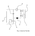
- Fig. 1 shows a designated in its entirety by 10 arrangement with in this example two LED strings 12, 14 each consisting of a number of series-connected LEDs 16, 18, of which - as indicated by the dashed lines - only the first and the Last LED are shown and between which more LEDs can be located.
- Each LED string 12, 14 is preceded by a ballast unit 20, 22, which comprises a voltage input for a voltage and a power output for outputting a power with a current and a voltage to the respective LED string.
- the current through the strand is measured at measuring points 24, 26, and the voltage applied to the respective strand is measured at measuring points 28, 30.
- a warning signal is generated in a manner known per se and not shown here. Then, for example, a central control and monitoring point can be forwarded, so that measures such as replacement of the affected LED string or switching to another strand can be initiated.
- FIG. 2 shows by way of example details of a typical construction of an output stage of a prior art LED power source for an in Fig. 1 shown arrangement.
- the LED string 12 shown a differential amplifier for measuring the voltage applied to the strand 12, symbolized by the arrow 32 voltage.
- a series circuit of a diode 36 and a transistor switch 38 is connected in addition to the LED strand 12, wherein the transistor switch 38 is connected to a controller 40.
- a resistor 42 is connected at one end to the LED string 12 and at its other end to both the transistor switch 38 and the diode 36. At high input voltages, the gain of the difference between the voltages 32 and 34 requires a high withstand voltage of the differential amplifier with a corresponding hardware cost.
- DE 10 2008 031 793 A1 and US 2009/0102398 A1 each show arrangements for monitoring a set of parallel-connected LED strings according to the preamble of claim 1.
- the invention has for its object to realize a cost-effective, but at the same time safe monitoring several parallel-connected LED strands, in which reduces the number of required measuring points compared to the prior art is, resulting in advantages in manufacturing, operating and maintenance costs.
- the invention relates to an arrangement for monitoring a set of parallel-connected LED strings, wherein each LED string has at least one LED or a series connection of several LEDs, and wherein the arrangement for each LED string a ballast unit with a voltage input for an input voltage and a Current output for supplying the respective LED string with power includes.
- the arrangement further comprises means for detecting a malfunction in the LED strings and generating a warning signal when a malfunction is detected.
- the means for detecting a malfunction comprise power detection means which detect the power consumption of the ballast units. If it is determined that the power consumption deviates from a predefinable setpoint, a warning signal can be generated.
- the invention is based on the idea not to monitor the current through each LED string and the voltage across each LED string, but to monitor the power consumption of each ballast unit, since the power consumption of the ballast units depends on the state of the LEDs in the respective string. If one LED fails, e.g. due to a short circuit or interruption, the power consumption of the LED and thus also that of the ballast unit changes.
- the design according to the invention reduces the number of measuring points required and thus the hardware complexity.
- Another great advantage of the invention is that the in Fig. 2 illustrated relatively complex voltage measurement on LEDs that are not directly connected to ground, can be omitted.
- the invention also relates to a method for monitoring a set of parallel-connected LED strings with the features of claim 5.
- Advantageous embodiments and further developments of the arrangement according to the invention and the method according to the invention are the subject of the respective subclaims.
- the independent claim 8 relates to an LED light, in particular in the form of a signal light for rail, sea or road transport or in the form of a vehicle lamp with a monitoring device according to the invention.
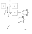
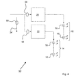
- FIGS. 3 to 5 Various arrangements are shown in a highly schematic form in the form of conventional circuit diagrams. In the process, those elements that have already been linked to the FIGS. 1 and 2 have been described and are known from the prior art, the same reference numerals associated with the corresponding elements in the FIGS. 1 and 2 , The Figures 3 and 5 are to Reference is shown and described while FIG. 4 an embodiment of the invention shows.
- each comprise two LED strands 12, 14 each consisting of a number of LEDs 16, 18, wherein each LED strand 12, 14 a separate ballast unit 20, 22 with a voltage input for one by the arrow 34, 34 'symbolized input voltage and a current output for powering the respective LED string 12, 14.
- each LED strand 12, 14 a separate ballast unit 20, 22 with a voltage input for one by the arrow 34, 34 'symbolized input voltage and a current output for powering the respective LED string 12, 14.
- the number of LEDs 16, 18 in each strand 12, 14 may be the same or different, and in particular, use cases in which only one LED is provided in each strand are conceivable.
- an arrangement designated 50 'in its entirety is shown in which the input voltage 34' is not constant.
- signal lights in daytime and nighttime operation are operated at different voltages to produce lighter, darker at night light signals.
- Other applications provide more than two or even continuously varying input voltages for stepping or stepless dimming of the LEDs.
- 22 recorded power to close the functionality of the LEDs in the respective strands, with variable input voltages a measurement of the respective input voltage is necessary, including the in Fig. 4 illustrated arrangement 50 'includes a voltage measuring point 58.
- Fig. 5 is a designated in its entirety by 50 "arrangement shown in which by means of a single current measuring point 54 ', the entire recorded by the Vorschaltikien 20, 22 in operation summed current is detected, so that then at a known input voltage 34 or, if the input voltage variable
- the individual ballast units receive similar power during normal operation, such an arrangement will not allow it to, as a rule, measure the total power consumption of the ballast units and compare it to a predetermined target value That is, to infer from a deviation of the total power consumed from a predetermined setpoint which of the LED strings is malfunctioning, there are certain applications where it is sufficient to detect that at least any one of the LED strings is malfunctioning.
- measuring points 54, 54 ', 56, 58 form power detection means and thus part of the means for detecting a malfunction in the LED strings.
- These means further include an evaluation unit known per se and not shown here for evaluating the measured values detected by the measuring points and for directly or indirectly comparing these values with predefinable setpoint values.
- an evaluation unit known per se and not shown here for evaluating the measured values detected by the measuring points and for directly or indirectly comparing these values with predefinable setpoint values.
- the current value detected by the measuring point 54 ' is compared directly with a predetermined current value (direct comparison).
- a warning signal can be generated and directed as described above to a central control and monitoring point. But it can also be provided that, for example, from as in connection with Fig. 4 first, a power consumption is calculated and then compared with one or more different predefinable desired values (indirect comparison). If different setpoint values are specified, it is also possible to select microcontroller-controlled in a manner known per se, which is the currently relevant setpoint value.
- each LED string has a specific function.
- a typical example of this are vehicle lights with at least one strand red and one strand of white LEDs, which can be alternately beschreibbut for identifying rail vehicles yes after the direction of travel.
- the invention allows advantageously to automate the prescribed in many countries, regulated in Germany for rail vehicles by EN61508-1, retesting the diagnostic function.
- the ballast devices can be easily dimensioned so that when switching from one function to another function, e.g. When switching from red light to white light, an error condition is generated for a certain time. This is detected by the means for detecting malfunctions, whereupon a corresponding warning signal is generated.
- a higher-level control system which has triggered the switching can then recognize from this (expected) warning signal that the means for detecting work correctly. If all functions implemented in the respective application are switched on once, an automatic repeat test according to EN61508-1 is carried out. This means that conventional test probes and repeat test intervals can be omitted.
Abstract
Anordnung (50) zur Überwachung eines Satzes von parallel geschalteten LED-Strängen (12, 14), wobei jeder LED-Strang (12, 14) wenigstens eine LED oder eine Reihenschaltung mehrerer LEDs (16, 18) aufweist, wobei für jeden LED-Strang (12, 14) eine Vorschalteinheit (20, 22) mit einem Spanungseingang für eine Eingangsspannung (34) aus einer gemeinsamen Spannungsquelle und einem Stromausgang zur Versorgung des jeweiligen LED-Strangs (12, 14) mit Strom vorgesehen ist, wobei Mittel zum Detektieren einer Fehlfunktion in den LED-Strängen (12, 14) und zum Erzeugen eines Warnsignals, wenn eine Fehlfunktion festgestellt wird, vorgesehen sind und wobei die Mittel zum Detektieren einer Fehlfunktion zwischen die Spannungsquelle und die Vorschalteinheiten (20, 22) geschaltete Leistungserfassungsmittel (54, 56) zur Erfassung der Leistungsaufnahme der Vorschalteinheiten (20, 22) umfassen und dazu ausgebildet sind, ein Warnsignal zu erzeugen, wenn die Leistungsaufnahme von einem vorgebbaren Sollwert abweicht.Arrangement (50) for monitoring a set of parallel-connected LED strings (12, 14), each LED string (12, 14) having at least one LED or a series connection of a plurality of LEDs (16, 18), wherein for each LED Strand (12, 14) a Vorschalteinheit (20, 22) having a voltage input for an input voltage (34) from a common voltage source and a current output for supplying current to the respective LED strand (12, 14) is provided, wherein means for detecting a malfunction in the LED strings (12, 14) and for generating a warning signal when a malfunction is detected, and wherein the means for detecting a malfunction between the voltage source and the Vorschalte units (20, 22) connected power detection means (54, 56) for detecting the power consumption of the ballast units (20, 22) and are adapted to generate a warning signal when the power consumption of a predetermined target value differs.
Description
Die Erfindung betrifft eine Anordnung und ein Verfahren zur Überwachung mehrerer LED-Stränge sowie eine LED-Leuchte mit einer solchen Anordnung, insbesondere in Form einer Signalleuchte für den See-, Luft-, Straßen- oder Schienenverkehr oder in Form einer Fahrzeugleuchte für ein Wasser, Luft-, Straßen- oder Schienenfahrzeug.The invention relates to an arrangement and a method for monitoring a plurality of LED strands and an LED light with such an arrangement, in particular in the form of a signal light for sea, air, road or rail transport or in the form of a vehicle light for a water, Air, road or rail vehicle.
Es ist bekannt, Leuchten mit mehreren "Strängen" von Leuchtmitteln auszustatten, die an eine gemeinsame Spannungsquelle ggf. unter Zwischenschaltung von für jeden Strang separaten Vorschalteinheiten angeschlossen werden und die nacheinander, abwechselnd oder ggf. auch gleichzeitig betrieben werden können. Im einfachsten Fall handelt es sich bei den Strängen um zwei Glühfäden, die in einer sog. Zwei-Faden-Glühlampen verwendet und dort üblicherweise als Haupt- und Nebenfaden (auch Ersatzfaden genannt) bezeichnet werden. Dabei dient der Nebenfaden dazu, ein Funktionieren der Glühlampe bei Ausfall des Hauptfadens zu sichern und somit quasi eine interne "Ersatzlampe" zu bilden. Bei Ausfall des Hauptfadens erfolgt die Umschaltung auf den Nebenfaden automatisch, wobei das Umschalten gleichzeitig als Störung erkannt wird, so dass der erforderliche Lampentausch dem Wartungspersonal angezeigt werden kann.It is known to equip luminaires with a plurality of "strands" of light sources, which are connected to a common voltage source, if necessary with the interposition of separate stranding units for each strand, and which can be operated successively, alternately or possibly also simultaneously. In the simplest case, the strands are two filaments, which are used in a so-called. Two-filament incandescent lamps and are usually referred to as the main and secondary thread (also called replacement thread). In this case, the secondary thread is used to ensure functioning of the light bulb in case of failure of the main thread and thus virtually to form an internal "replacement lamp". In case of failure of the main thread switching to the secondary thread is done automatically, the switching is detected as a fault at the same time, so that the required lamp replacement can be displayed to the maintenance personnel.
Aufgrund der zahlreichen Vorteile der LED-Technik und der Entwicklung immer leistungsfähigerer LEDs lösen LED-Leuchten in unzähligen, teilweise auch sicherheitsrelevanten Bereichen klassische Leuchtmittel ab.Due to the numerous advantages of LED technology and the development of more and more powerful LEDs, LED luminaires replace traditional light sources in innumerable, in part also safety-relevant areas.
Während allerdings bei klassischen Leuchtmitteln die Überwachung des korrekten Funktionierens meist einfach realisiert werden kann ist (in der Regel genügt es, zu überwachen, ob Strom durch das Leuchtmittel fließt oder nicht; wenn trotz angelegter Spannung kein Strom durch das Leuchtmittel fließt, kann davon ausgegangen werden, dass das Leuchtmittel defekt ist und getauscht werden muss), ist die Funktionsüberwachung bei LEDs aus verschiedenen Gründen nicht trivial. So kann es z.B. dazu kommen, dass eine LED nicht leuchtet, obwohl Strom durch sie fließt.While, however, the monitoring of the correct functioning is usually easy to realize in the case of classic illuminants (it is generally sufficient to monitor whether or not current flows through the luminous means), if no current flows through the illuminant despite the applied voltage, this can be assumed that the bulb is defective and must be replaced) is the Function monitoring of LEDs is not trivial for various reasons. For example, it may happen that an LED is not lit, even though current is flowing through it.
Zur sicheren Überwachung wird deshalb bislang pro LED-Strang eine kombinierte Strom-Spannungs-Überwachung eingesetzt, so dass bei N überwachten Strängen (wobei N eine ganze Zahl größer oder gleich 1 bezeichnet), 2 x N Messstellen vorgesehen werden müssen. Jeder Strang kann dabei aus einer oder mehreren LEDs bestehen. Eine Unterbrechung in einer LED führt dazu, dass der Strom über den diese LED enthaltenden Strang auf null zurückgeht. Eine kurzgeschlossene ("durchlegierte") LED führt zu einer verringerten Flussspannung über den diese LED enthaltenden Strang.For safe monitoring, a combined current-voltage monitoring has been used so far per LED string, so that N monitored strands (where N is an integer greater than or equal to 1), 2 x N measuring points must be provided. Each strand can consist of one or more LEDs. A break in an LED causes the current across the string containing that LED to go back to zero. A shorted ("light alloyed") LED results in a reduced forward voltage across the string containing this LED.
Aus der
Die aus dem Stand der Technik bekannte Konzeption zur Überwachung von LED-Strängen ist in den
Neben der Tatsache, dass bei der beschriebenen Anordnung für N Stränge 2N Messstellen vorgesehen werden müssen, ist zudem die Spannungsmessung an LEDs, die nicht direkt gegen Masse geschaltet sind, nicht trivial.
Parallel zu einer Spannungsquelle für eine durch den Pfeil 34 symbolisierte Eingangsspannung ist zusätzlich zum LED-Strang 12 eine Reihenschaltung aus einer Diode 36 und einem Transistorschalter 38 geschaltet, wobei der Transistorschalter 38 mit einer Steuerung 40 geschaltet wird.Parallel to a voltage source for symbolized by the
Ein Widerstand 42 ist an einem Ende mit dem LED-Strang 12 und an seinem anderen Ende sowohl mit dem Transistorschalter 38 als auch der Diode 36 verbunden. Bei hohen Eingangsspannungen erfordert die Verstärkung der Differenz zwischen den Spannungen 32 und 34 eine hohe Spannungsfestigkeit des Differenzverstärkers mit entsprechendem Hardwareaufwand.A
Die Druckschriften
Der Erfindung liegt die Aufgabe zugrunde, eine kostengünstige, gleichzeitig aber auch sichere Überwachung mehrerer parallel geschalteter LED-Stränge zu realisieren, bei der die Anzahl der benötigten Messstellen gegenüber dem Stand der Technik reduziert ist, wodurch sich Vorteile bei den Herstellungs-, Betriebs- und Wartungskosten ergeben.The invention has for its object to realize a cost-effective, but at the same time safe monitoring several parallel-connected LED strands, in which reduces the number of required measuring points compared to the prior art is, resulting in advantages in manufacturing, operating and maintenance costs.
Dazu betrifft die Erfindung eine Anordnung zur Überwachung eines Satzes von parallel geschalteten LED-Strängen, wobei jeder LED-Strang wenigstens eine LED oder eine Reihenschaltung mehrerer LEDs aufweist und wobei die Anordnung für jeden LED-Strang eine Vorschalteinheit mit einem Spannungseingang für eine Eingangsspannung und einem Stromausgang zur Versorgung des jeweiligen LED-Strangs mit Strom umfasst. Die Anordnung umfasst ferner Mittel zum Detektieren einer Fehlfunktion in den LED-Strängen und zum Erzeugen eines Warnsignals, wenn eine Fehlfunktion festgestellt wird. Erfindungsgemäß weisen die Mittel zum Detektieren einer Fehlfunktion Leistungserfassungsmittel auf, die die Leistungsaufnahme der Vorschalteinheiten erfassen. Wird festgestellt, dass die die Leistungsaufnahme von einem vorgebbaren Sollwert abweicht, kann ein Warnsignal erzeugt werden.To this end, the invention relates to an arrangement for monitoring a set of parallel-connected LED strings, wherein each LED string has at least one LED or a series connection of several LEDs, and wherein the arrangement for each LED string a ballast unit with a voltage input for an input voltage and a Current output for supplying the respective LED string with power includes. The arrangement further comprises means for detecting a malfunction in the LED strings and generating a warning signal when a malfunction is detected. According to the invention, the means for detecting a malfunction comprise power detection means which detect the power consumption of the ballast units. If it is determined that the power consumption deviates from a predefinable setpoint, a warning signal can be generated.
Die Erfindung beruht auf dem Gedanken, nicht den Strom durch jeden LED-Strang und die Spannung über jeden LED-Strang zu überwachen, sondern die Leistungsaufnahme jeder Vorschalteinheit zu überwachen, da die Leistungsaufnahme der Vorschalteinheiten vom Zustand der LEDs in dem jeweiligen Strang abhängig ist. Beim Ausfall einer LED z.B. durch Kurzschluss oder Unterbrechung ändert sich die Leistungsaufnahme der LED und damit auch diejenige der Vorschalteinheit.The invention is based on the idea not to monitor the current through each LED string and the voltage across each LED string, but to monitor the power consumption of each ballast unit, since the power consumption of the ballast units depends on the state of the LEDs in the respective string. If one LED fails, e.g. due to a short circuit or interruption, the power consumption of the LED and thus also that of the ballast unit changes.
Wie nachfolgend noch dargelegt wird, erniedrigt sich durch die erfindungsgemäße Ausgestaltung die Anzahl der benötigen Messstellen und damit der Hardwareaufwand. Ein weiterer großer Vorteil der Erfindung ist, dass die in
Die Erfindung betrifft auch ein Verfahren zur Überwachung eines Satzes von parallel geschalteten LED-Strängen mit den Merkmalen des Anspruchs 5. Vorteilhafte Ausgestaltungen und Weiterbildungen der erfindungsgemäßen Anordnung und des erfindungsgemäßen Verfahrens sind Gegenstand der jeweiligen Unteransprüche. Der nebengeordnete Anspruch 8 betrifft eine LED-Leuchte insbesondere in Form einer Signalleuchte für den Schienen-, See- oder Straßenverkehr oder in Form einer Fahrzeugleuchte mit einer erfindungsgemäßen Überwachungsanordnung.The invention also relates to a method for monitoring a set of parallel-connected LED strings with the features of claim 5. Advantageous embodiments and further developments of the arrangement according to the invention and the method according to the invention are the subject of the respective subclaims. The independent claim 8 relates to an LED light, in particular in the form of a signal light for rail, sea or road transport or in the form of a vehicle lamp with a monitoring device according to the invention.
Weitere Einzelheiten und Vorteile der Erfindung ergeben sich aus der nachfolgenden rein beispielhaften und nicht-beschränkenden Beschreibung von Ausführungsbeispielen in Verbindung mit der Zeichnung.Further details and advantages of the invention will become apparent from the following purely exemplary and non-limiting description of embodiments in conjunction with the drawings.
- Fig. 1Fig. 1
- zeigt schematisch eine Anordnung zur Überwachung eines Satzes von parallel geschalteten LED-Strängen gemäß dem Stand der Technik.1 schematically shows an arrangement for monitoring a set of parallel-connected LED strings according to the prior art.
- Fig. 2Fig. 2
-
zeigt schematisch eine Schaltung mit einem Differenzverstärker zur Spannungsmessung bei der in
Fig. 1 gezeigten Anordnung.schematically shows a circuit with a differential amplifier for voltage measurement in the inFig. 1 shown arrangement. - Fig. 3Fig. 3
- zeigt stark schematisiert ein erstes Ausführungsbeispiel einer Anordnung zur Überwachung eines Satzes von LED-Strängen, wobei die jedem Strang zugeordneten Vorschalteinheiten mit einer konstanten Eingangsspannung versorgt werden.shows a highly schematic of a first embodiment of an arrangement for monitoring a set of LED strings, wherein the each strand associated Vorschalteinheiten be supplied with a constant input voltage.
- Fig. 4Fig. 4
- zeigt eine erfindungsgemäße Anordnung, bei der die Eingangsspannung, mit der die Vorschalteinheiten versorgt werden, nicht konstant ist.shows an arrangement according to the invention, in which the input voltage, with which the Vorschalteinheiten are supplied, is not constant.
- Fig. 5Fig. 5
- zeigt eine weiter vereinfachte Anordnung, bei der die Leistungsaufnahme der Vorschalteinheiten summarisch erfasst wird.shows a further simplified arrangement in which the power consumption of the Vorschalteinheiten is summarily detected.
In den
Alle drei der in den
Bei der in
In der
In der
Die in den
Bei bestimmten Anwendungsfällen gilt es, einen Satz von wenigstens zwei parallel geschalteten LED-Strängen zu überwachen, wobei jeder LED-Strang eine bestimmte Funktion hat. Ein typisches Beispiel hierfür sind Fahrzeugleuchten mit wenigstens einem Strang roter und einem Strang weißer LEDs, die zum Kenntlichmachen von Schienenfahrzeugen ja nach dessen Fahrtrichtung wechselweise bestrieben werden können. Bei solchen Anwendungsfällen erlaubt es die Erfindung vorteilhaft, die in vielen Ländern vorgeschriebene, in Deutschland für Schienenfahrzeuge durch die EN61508-1 geregelte, Wiederholungsprüfung der Diagnosefunktion zu automatisieren. Dazu können die Vorschalteinrichtungen in einfacher Weise so dimensioniert werden, dass beim Umschalten von einer Funktion auf eine andere Funktion, also z.B. beim Umschalten von rotem Licht auf weißes Licht, für eine gewisse Zeit ein Fehlerzustand erzeugt wird. Dieser wird von den Mitteln zum Detektieren von Fehlfunktionen erkannt, worauf ein entsprechendes Warnsignal erzeugt wird. Eine übergeordnete Steuerung, die das Umschalten ausgelöst hat, kann dann an diesem (erwarteten) Warnsignal erkennen, dass die Mittel zum Detektieren korrekt arbeiten. Werden alle im jeweiligen Anwendungsfall realisierten Funktionen einmal eingeschaltet, so ist eine automatische Wiederholungsprüfung gemäß EN61508-1 durchgeführt. Damit können bislang übliche Testtaster und Wiederholungsprüfintervalle entfallen.In certain applications, it is necessary to monitor a set of at least two parallel-connected LED strings, each LED string has a specific function. A typical example of this are vehicle lights with at least one strand red and one strand of white LEDs, which can be alternately beschreibmachen for identifying rail vehicles yes after the direction of travel. In such applications, the invention allows advantageously to automate the prescribed in many countries, regulated in Germany for rail vehicles by EN61508-1, retesting the diagnostic function. For this purpose, the ballast devices can be easily dimensioned so that when switching from one function to another function, e.g. When switching from red light to white light, an error condition is generated for a certain time. This is detected by the means for detecting malfunctions, whereupon a corresponding warning signal is generated. A higher-level control system which has triggered the switching can then recognize from this (expected) warning signal that the means for detecting work correctly. If all functions implemented in the respective application are switched on once, an automatic repeat test according to EN61508-1 is carried out. This means that conventional test probes and repeat test intervals can be omitted.
Im Rahmen des Erfindungsgedankens sind zahlreiche Abwandlungen und Weiterbildungen möglich, die sich z.B. auf die Art und Anzahl der Messstellen beziehen. Erfindungswesentlich ist jedenfalls die Idee, nicht mehr direkt die einzelnen LED-Stränge zu überwachen, sondern die Leistungsaufnahme der Vorschalteinheiten, um so quasi indirekt auf das Funktionieren der LED-Stränge zu schließen. Die erfindungsgemäße Anordnung und das erfindungsgemäße Verfahren können vorteilhaft bei völlig unterschiedlichen Anwendungsfällen eingesetzt werden. Ein typischer Anwendungsfall sind Signalleuchten mit mehreren LED-Strängen, die, z.B. zur gleichmäßigen Abnutzung, jeweils alternierend betrieben werden. Wird dann detektiert, dass ein bestimmter Strang ausgefallen ist, kann ein Warnsignal erzeugt werden, das einer zentralen Steuerstelle anzeigt, dass die entsprechende Leuchte alsbald ausgetauscht werden sollte. Bis zum Austausch der Leuchte können dann aber der andere LED-Strang oder die weiteren LED-Stränge verwendet werden.Within the scope of the inventive concept, numerous modifications and developments are possible, which relate, for example, to the type and number of measuring points. At least essential to the invention is the idea of no longer directly monitoring the individual LED strings, but rather the power consumption of the ballast units in order to close, as it were, indirectly on the functioning of the LED strings. The Inventive arrangement and the inventive method can be advantageously used in completely different applications. A typical application are signal lights with multiple LED strands, which are operated alternately, for example, for uniform wear. If it is then detected that a certain strand has failed, a warning signal can be generated which indicates to a central control station that the corresponding luminaire should be replaced soon. Until the lamp is replaced, however, the other LED string or the other LED strings can be used.
- 1010
- LED-MehrstrandanordnungLED More beach arrangement
- 1212
- LED-StrangLED cluster
- 1414
- LED-StrangLED cluster
- 1616
-
LEDs in Strang 12LEDs in
strand 12 - 1818
-
LEDs in Strang 14LEDs in
strand 14 - 2020
-
Vorschalteinheit zur Versorgung von LED-Strang 12Ballast unit for supplying
LED string 12 - 2222
-
Vorschalteinheit zur Versorgung von LED-Strang 14Ballast unit for supplying
LED string 14 - 2424
-
Messstelle für Strom im LED-Strang 12Measuring point for current in the
LED string 12 - 2626
-
Messstelle für Strom im LED-Strang 14Measuring point for current in the
LED string 14 - 2828
-
Messstelle für Spannung am LED-Strang 12Measuring point for voltage at the
LED string 12 - 3030
-
Messstelle für Spannung am LED-Strang 14Measuring point for voltage at the
LED string 14 - 3232
-
Spannung am LED-Strang 12Voltage on the
LED string 12 - 34, 34'34, 34 '
- Eingangsspannunginput voltage
- 3636
- Diodediode
- 3838
- Transistorschaltertransistor switch
- 4040
- Steuerungcontrol
- 4242
- Widerstandresistance
- 50, 50', 50"50, 50 ', 50 "
- LED-MehrstranganordnungLED multi-strand arrangement
- 5252
- KonstantspannungsquelleConstant voltage source
- 54, 54'54, 54 '
- Messstelle für StromMeasuring point for electricity
- 5656
- Messstelle für StromMeasuring point for electricity
- 5858
- Messstelle für SpannungMeasuring point for voltage
Claims (8)
dadurch gekennzeichnet,
characterized,
dadurch gekennzeichnet,
characterized,
Applications Claiming Priority (1)
| Application Number | Priority Date | Filing Date | Title |
|---|---|---|---|
| DE201310110838 DE102013110838B3 (en) | 2013-09-30 | 2013-09-30 | Arrangement and method for monitoring a plurality of LED strands and LED light with such an arrangement |
Publications (3)
| Publication Number | Publication Date |
|---|---|
| EP2866524A2 true EP2866524A2 (en) | 2015-04-29 |
| EP2866524A3 EP2866524A3 (en) | 2015-06-17 |
| EP2866524B1 EP2866524B1 (en) | 2018-12-19 |
Family
ID=51263335
Family Applications (1)
| Application Number | Title | Priority Date | Filing Date |
|---|---|---|---|
| EP14179928.8A Active EP2866524B1 (en) | 2013-09-30 | 2014-08-05 | Assembly and method for monitoring a plurality of LED strings and LED lamp with such an assembly |
Country Status (3)
| Country | Link |
|---|---|
| EP (1) | EP2866524B1 (en) |
| DE (1) | DE102013110838B3 (en) |
| ES (1) | ES2711206T3 (en) |
Families Citing this family (2)
| Publication number | Priority date | Publication date | Assignee | Title |
|---|---|---|---|---|
| DE102016103871A1 (en) * | 2016-03-03 | 2017-09-07 | Washtec Holding Gmbh | Method and device for automatically detecting the configuration of luminous elements connected in series |
| EP3787374A1 (en) * | 2019-08-30 | 2021-03-03 | Siemens Mobility AG | System and method for checking the luminance of a light point equipped with at least one led illuminant |
Citations (6)
| Publication number | Priority date | Publication date | Assignee | Title |
|---|---|---|---|---|
| DE19749333A1 (en) | 1997-09-19 | 1999-03-25 | Garufo Gmbh | Light signal consisting of LEDs connected to voltage via current source |
| DE102006056147A1 (en) | 2006-11-28 | 2008-06-05 | Siemens Ag | Light-emitting semiconductor components function monitoring method for e.g. light signals at level crossings, involves detecting change of power input for recognition of failure of semiconductor components |
| EP1992542A2 (en) | 2007-05-07 | 2008-11-19 | Pintsch Bamag Antriebs- und Verkehrstechnik GmbH | LED arrangement for light signal emitter, especially for rail transfers, light signal emitter especially for rail transfers with such an LED arrangement and method of operating the LED arrangement |
| DE102008031793A1 (en) | 2007-07-06 | 2009-01-08 | Koito Manufacturing Co., Ltd. | Lighting control device of a lighting device for a vehicle |
| US20090102398A1 (en) | 2007-10-18 | 2009-04-23 | Andrea Becattini | Lighting unit, a system comprising it and a control method thereof |
| US20120313528A1 (en) | 2011-06-09 | 2012-12-13 | Osram Sylvania Inc. | Multiple channel light source power supply with output protection |
Family Cites Families (4)
| Publication number | Priority date | Publication date | Assignee | Title |
|---|---|---|---|---|
| US6150771A (en) * | 1997-06-11 | 2000-11-21 | Precision Solar Controls Inc. | Circuit for interfacing between a conventional traffic signal conflict monitor and light emitting diodes replacing a conventional incandescent bulb in the signal |
| DE102005012625B4 (en) * | 2005-03-18 | 2009-01-02 | Infineon Technologies Ag | Method and circuit arrangement for controlling LEDs |
| DE102008044666A1 (en) * | 2008-08-28 | 2010-03-11 | Erich Jaeger Gmbh & Co. Kg | Lights e.g. lamps, testing method for e.g. motor vehicle trailer, involves measuring comparison current value, and testing function of lights based on comparison of value of current flowing through lights with measured value |
| DE102012101363A1 (en) * | 2012-02-21 | 2013-08-22 | Hella Kgaa Hueck & Co. | Method for operating a circuit arrangement with a control and / or regulating means for a light-emitting diode array |
-
2013
- 2013-09-30 DE DE201310110838 patent/DE102013110838B3/en not_active Expired - Fee Related
-
2014
- 2014-08-05 EP EP14179928.8A patent/EP2866524B1/en active Active
- 2014-08-05 ES ES14179928T patent/ES2711206T3/en active Active
Patent Citations (6)
| Publication number | Priority date | Publication date | Assignee | Title |
|---|---|---|---|---|
| DE19749333A1 (en) | 1997-09-19 | 1999-03-25 | Garufo Gmbh | Light signal consisting of LEDs connected to voltage via current source |
| DE102006056147A1 (en) | 2006-11-28 | 2008-06-05 | Siemens Ag | Light-emitting semiconductor components function monitoring method for e.g. light signals at level crossings, involves detecting change of power input for recognition of failure of semiconductor components |
| EP1992542A2 (en) | 2007-05-07 | 2008-11-19 | Pintsch Bamag Antriebs- und Verkehrstechnik GmbH | LED arrangement for light signal emitter, especially for rail transfers, light signal emitter especially for rail transfers with such an LED arrangement and method of operating the LED arrangement |
| DE102008031793A1 (en) | 2007-07-06 | 2009-01-08 | Koito Manufacturing Co., Ltd. | Lighting control device of a lighting device for a vehicle |
| US20090102398A1 (en) | 2007-10-18 | 2009-04-23 | Andrea Becattini | Lighting unit, a system comprising it and a control method thereof |
| US20120313528A1 (en) | 2011-06-09 | 2012-12-13 | Osram Sylvania Inc. | Multiple channel light source power supply with output protection |
Also Published As
| Publication number | Publication date |
|---|---|
| EP2866524B1 (en) | 2018-12-19 |
| EP2866524A3 (en) | 2015-06-17 |
| ES2711206T3 (en) | 2019-04-30 |
| DE102013110838B3 (en) | 2015-02-12 |
Similar Documents
| Publication | Publication Date | Title |
|---|---|---|
| DE102014107947A1 (en) | LED unit with voltage monitoring, use of such a LED unit and LED light with such a LED unit | |
| EP2131628B1 (en) | Signal issuer | |
| EP2247161A1 (en) | Malfunction recognition for illumination devices in motor vehicle lights | |
| EP2353346B1 (en) | Lighting system having security lighting | |
| EP2866524B1 (en) | Assembly and method for monitoring a plurality of LED strings and LED lamp with such an assembly | |
| DE10359196B4 (en) | Lighting device for a motor vehicle | |
| DE10236862B4 (en) | Circuit arrangement for power supply and for controlling light-emitting diode arrangements, in particular in vehicle lights | |
| EP2687418B1 (en) | LED track signal for rail transport and interface for such an LED track signal | |
| EP1753267A1 (en) | Lighting device for vehicle lamps | |
| EP2329686A1 (en) | Method for operating a series circuit of at least two led s | |
| DE102008029725A1 (en) | signaler | |
| DE102008000086B4 (en) | Method for failure control of light functions in a motor vehicle electrical system | |
| DE102007001716B4 (en) | Light-emitting diode circuit arrangement and method for operating a light-emitting diode circuit arrangement | |
| DE10324609B4 (en) | Control circuit and LED array and method for operating an LED array | |
| EP3072775B1 (en) | Method for indicating the lighting of a signal light in a traffic signal to a monitoring device | |
| DE60209677T2 (en) | Light information device for displaying the operating state of a system, in particular for avionics | |
| DE10206649A1 (en) | display device | |
| EP3787379A1 (en) | System and method for checking the luminance of a light point equipped with at least one led illuminant | |
| AT517122A1 (en) | Lighting device for vehicles | |
| AT511094B1 (en) | ARRANGEMENT FOR STATE MONITORING OF A LAMP | |
| DE19955743C1 (en) | Display device | |
| EP1096834A2 (en) | Display device with luminescent elements | |
| DE102012019861B4 (en) | Method for operating a signal transmitter and signal transmitter | |
| EP1286571A2 (en) | Electronically secured power supply for a circuit group and display for variable information | |
| DE10358993B4 (en) | Light signal transmitter and traffic signal system with a light signal transmitter |
Legal Events
| Date | Code | Title | Description |
|---|---|---|---|
| PUAI | Public reference made under article 153(3) epc to a published international application that has entered the european phase |
Free format text: ORIGINAL CODE: 0009012 |
|
| 17P | Request for examination filed |
Effective date: 20140805 |
|
| AK | Designated contracting states |
Kind code of ref document: A2 Designated state(s): AL AT BE BG CH CY CZ DE DK EE ES FI FR GB GR HR HU IE IS IT LI LT LU LV MC MK MT NL NO PL PT RO RS SE SI SK SM TR |
|
| AX | Request for extension of the european patent |
Extension state: BA ME |
|
| PUAL | Search report despatched |
Free format text: ORIGINAL CODE: 0009013 |
|
| AK | Designated contracting states |
Kind code of ref document: A3 Designated state(s): AL AT BE BG CH CY CZ DE DK EE ES FI FR GB GR HR HU IE IS IT LI LT LU LV MC MK MT NL NO PL PT RO RS SE SI SK SM TR |
|
| AX | Request for extension of the european patent |
Extension state: BA ME |
|
| RIC1 | Information provided on ipc code assigned before grant |
Ipc: B60Q 11/00 20060101ALI20150508BHEP Ipc: H05B 33/08 20060101AFI20150508BHEP Ipc: B61L 5/18 20060101ALI20150508BHEP Ipc: H05B 37/03 20060101ALI20150508BHEP Ipc: B61L 7/10 20060101ALI20150508BHEP |
|
| R17P | Request for examination filed (corrected) |
Effective date: 20150730 |
|
| RBV | Designated contracting states (corrected) |
Designated state(s): AL AT BE BG CH CY CZ DE DK EE ES FI FR GB GR HR HU IE IS IT LI LT LU LV MC MK MT NL NO PL PT RO RS SE SI SK SM TR |
|
| STAA | Information on the status of an ep patent application or granted ep patent |
Free format text: STATUS: EXAMINATION IS IN PROGRESS |
|
| 17Q | First examination report despatched |
Effective date: 20170123 |
|
| RAP1 | Party data changed (applicant data changed or rights of an application transferred) |
Owner name: SCHALTBAU REFURBISHMENT GMBH |
|
| GRAP | Despatch of communication of intention to grant a patent |
Free format text: ORIGINAL CODE: EPIDOSNIGR1 |
|
| STAA | Information on the status of an ep patent application or granted ep patent |
Free format text: STATUS: GRANT OF PATENT IS INTENDED |
|
| INTG | Intention to grant announced |
Effective date: 20180530 |
|
| GRAJ | Information related to disapproval of communication of intention to grant by the applicant or resumption of examination proceedings by the epo deleted |
Free format text: ORIGINAL CODE: EPIDOSDIGR1 |
|
| STAA | Information on the status of an ep patent application or granted ep patent |
Free format text: STATUS: EXAMINATION IS IN PROGRESS |
|
| GRAP | Despatch of communication of intention to grant a patent |
Free format text: ORIGINAL CODE: EPIDOSNIGR1 |
|
| STAA | Information on the status of an ep patent application or granted ep patent |
Free format text: STATUS: GRANT OF PATENT IS INTENDED |
|
| INTC | Intention to grant announced (deleted) | ||
| INTG | Intention to grant announced |
Effective date: 20180917 |
|
| RIN1 | Information on inventor provided before grant (corrected) |
Inventor name: GOLLBACH, MARTIN Inventor name: KRAUSE, WERNER |
|
| GRAS | Grant fee paid |
Free format text: ORIGINAL CODE: EPIDOSNIGR3 |
|
| GRAJ | Information related to disapproval of communication of intention to grant by the applicant or resumption of examination proceedings by the epo deleted |
Free format text: ORIGINAL CODE: EPIDOSDIGR1 |
|
| GRAL | Information related to payment of fee for publishing/printing deleted |
Free format text: ORIGINAL CODE: EPIDOSDIGR3 |
|
| STAA | Information on the status of an ep patent application or granted ep patent |
Free format text: STATUS: EXAMINATION IS IN PROGRESS |
|
| GRAR | Information related to intention to grant a patent recorded |
Free format text: ORIGINAL CODE: EPIDOSNIGR71 |
|
| STAA | Information on the status of an ep patent application or granted ep patent |
Free format text: STATUS: GRANT OF PATENT IS INTENDED |
|
| GRAA | (expected) grant |
Free format text: ORIGINAL CODE: 0009210 |
|
| STAA | Information on the status of an ep patent application or granted ep patent |
Free format text: STATUS: THE PATENT HAS BEEN GRANTED |
|
| INTC | Intention to grant announced (deleted) | ||
| AK | Designated contracting states |
Kind code of ref document: B1 Designated state(s): AL AT BE BG CH CY CZ DE DK EE ES FI FR GB GR HR HU IE IS IT LI LT LU LV MC MK MT NL NO PL PT RO RS SE SI SK SM TR |
|
| INTG | Intention to grant announced |
Effective date: 20181112 |
|
| REG | Reference to a national code |
Ref country code: GB Ref legal event code: FG4D Free format text: NOT ENGLISH |
|
| REG | Reference to a national code |
Ref country code: CH Ref legal event code: EP |
|
| REG | Reference to a national code |
Ref country code: IE Ref legal event code: FG4D Free format text: LANGUAGE OF EP DOCUMENT: GERMAN |
|
| REG | Reference to a national code |
Ref country code: DE Ref legal event code: R096 Ref document number: 502014010367 Country of ref document: DE |
|
| REG | Reference to a national code |
Ref country code: AT Ref legal event code: REF Ref document number: 1080080 Country of ref document: AT Kind code of ref document: T Effective date: 20190115 |
|
| REG | Reference to a national code |
Ref country code: NL Ref legal event code: MP Effective date: 20181219 |
|
| PG25 | Lapsed in a contracting state [announced via postgrant information from national office to epo] |
Ref country code: NO Free format text: LAPSE BECAUSE OF FAILURE TO SUBMIT A TRANSLATION OF THE DESCRIPTION OR TO PAY THE FEE WITHIN THE PRESCRIBED TIME-LIMIT Effective date: 20190319 Ref country code: FI Free format text: LAPSE BECAUSE OF FAILURE TO SUBMIT A TRANSLATION OF THE DESCRIPTION OR TO PAY THE FEE WITHIN THE PRESCRIBED TIME-LIMIT Effective date: 20181219 Ref country code: LT Free format text: LAPSE BECAUSE OF FAILURE TO SUBMIT A TRANSLATION OF THE DESCRIPTION OR TO PAY THE FEE WITHIN THE PRESCRIBED TIME-LIMIT Effective date: 20181219 Ref country code: BG Free format text: LAPSE BECAUSE OF FAILURE TO SUBMIT A TRANSLATION OF THE DESCRIPTION OR TO PAY THE FEE WITHIN THE PRESCRIBED TIME-LIMIT Effective date: 20190319 Ref country code: HR Free format text: LAPSE BECAUSE OF FAILURE TO SUBMIT A TRANSLATION OF THE DESCRIPTION OR TO PAY THE FEE WITHIN THE PRESCRIBED TIME-LIMIT Effective date: 20181219 Ref country code: LV Free format text: LAPSE BECAUSE OF FAILURE TO SUBMIT A TRANSLATION OF THE DESCRIPTION OR TO PAY THE FEE WITHIN THE PRESCRIBED TIME-LIMIT Effective date: 20181219 |
|
| REG | Reference to a national code |
Ref country code: ES Ref legal event code: FG2A Ref document number: 2711206 Country of ref document: ES Kind code of ref document: T3 Effective date: 20190430 |
|
| REG | Reference to a national code |
Ref country code: LT Ref legal event code: MG4D |
|
| PG25 | Lapsed in a contracting state [announced via postgrant information from national office to epo] |
Ref country code: RS Free format text: LAPSE BECAUSE OF FAILURE TO SUBMIT A TRANSLATION OF THE DESCRIPTION OR TO PAY THE FEE WITHIN THE PRESCRIBED TIME-LIMIT Effective date: 20181219 Ref country code: AL Free format text: LAPSE BECAUSE OF FAILURE TO SUBMIT A TRANSLATION OF THE DESCRIPTION OR TO PAY THE FEE WITHIN THE PRESCRIBED TIME-LIMIT Effective date: 20181219 Ref country code: SE Free format text: LAPSE BECAUSE OF FAILURE TO SUBMIT A TRANSLATION OF THE DESCRIPTION OR TO PAY THE FEE WITHIN THE PRESCRIBED TIME-LIMIT Effective date: 20181219 Ref country code: GR Free format text: LAPSE BECAUSE OF FAILURE TO SUBMIT A TRANSLATION OF THE DESCRIPTION OR TO PAY THE FEE WITHIN THE PRESCRIBED TIME-LIMIT Effective date: 20190320 |
|
| PG25 | Lapsed in a contracting state [announced via postgrant information from national office to epo] |
Ref country code: NL Free format text: LAPSE BECAUSE OF FAILURE TO SUBMIT A TRANSLATION OF THE DESCRIPTION OR TO PAY THE FEE WITHIN THE PRESCRIBED TIME-LIMIT Effective date: 20181219 |
|
| PG25 | Lapsed in a contracting state [announced via postgrant information from national office to epo] |
Ref country code: PL Free format text: LAPSE BECAUSE OF FAILURE TO SUBMIT A TRANSLATION OF THE DESCRIPTION OR TO PAY THE FEE WITHIN THE PRESCRIBED TIME-LIMIT Effective date: 20181219 Ref country code: IT Free format text: LAPSE BECAUSE OF FAILURE TO SUBMIT A TRANSLATION OF THE DESCRIPTION OR TO PAY THE FEE WITHIN THE PRESCRIBED TIME-LIMIT Effective date: 20181219 Ref country code: CZ Free format text: LAPSE BECAUSE OF FAILURE TO SUBMIT A TRANSLATION OF THE DESCRIPTION OR TO PAY THE FEE WITHIN THE PRESCRIBED TIME-LIMIT Effective date: 20181219 Ref country code: PT Free format text: LAPSE BECAUSE OF FAILURE TO SUBMIT A TRANSLATION OF THE DESCRIPTION OR TO PAY THE FEE WITHIN THE PRESCRIBED TIME-LIMIT Effective date: 20190419 |
|
| PG25 | Lapsed in a contracting state [announced via postgrant information from national office to epo] |
Ref country code: SK Free format text: LAPSE BECAUSE OF FAILURE TO SUBMIT A TRANSLATION OF THE DESCRIPTION OR TO PAY THE FEE WITHIN THE PRESCRIBED TIME-LIMIT Effective date: 20181219 Ref country code: EE Free format text: LAPSE BECAUSE OF FAILURE TO SUBMIT A TRANSLATION OF THE DESCRIPTION OR TO PAY THE FEE WITHIN THE PRESCRIBED TIME-LIMIT Effective date: 20181219 Ref country code: SM Free format text: LAPSE BECAUSE OF FAILURE TO SUBMIT A TRANSLATION OF THE DESCRIPTION OR TO PAY THE FEE WITHIN THE PRESCRIBED TIME-LIMIT Effective date: 20181219 Ref country code: RO Free format text: LAPSE BECAUSE OF FAILURE TO SUBMIT A TRANSLATION OF THE DESCRIPTION OR TO PAY THE FEE WITHIN THE PRESCRIBED TIME-LIMIT Effective date: 20181219 Ref country code: IS Free format text: LAPSE BECAUSE OF FAILURE TO SUBMIT A TRANSLATION OF THE DESCRIPTION OR TO PAY THE FEE WITHIN THE PRESCRIBED TIME-LIMIT Effective date: 20190419 |
|
| REG | Reference to a national code |
Ref country code: DE Ref legal event code: R097 Ref document number: 502014010367 Country of ref document: DE |
|
| PLBE | No opposition filed within time limit |
Free format text: ORIGINAL CODE: 0009261 |
|
| STAA | Information on the status of an ep patent application or granted ep patent |
Free format text: STATUS: NO OPPOSITION FILED WITHIN TIME LIMIT |
|
| PG25 | Lapsed in a contracting state [announced via postgrant information from national office to epo] |
Ref country code: DK Free format text: LAPSE BECAUSE OF FAILURE TO SUBMIT A TRANSLATION OF THE DESCRIPTION OR TO PAY THE FEE WITHIN THE PRESCRIBED TIME-LIMIT Effective date: 20181219 |
|
| REG | Reference to a national code |
Ref country code: DE Ref legal event code: R079 Ref document number: 502014010367 Country of ref document: DE Free format text: PREVIOUS MAIN CLASS: H05B0033080000 Ipc: H05B0045000000 |
|
| 26N | No opposition filed |
Effective date: 20190920 |
|
| PG25 | Lapsed in a contracting state [announced via postgrant information from national office to epo] |
Ref country code: SI Free format text: LAPSE BECAUSE OF FAILURE TO SUBMIT A TRANSLATION OF THE DESCRIPTION OR TO PAY THE FEE WITHIN THE PRESCRIBED TIME-LIMIT Effective date: 20181219 |
|
| PG25 | Lapsed in a contracting state [announced via postgrant information from national office to epo] |
Ref country code: TR Free format text: LAPSE BECAUSE OF FAILURE TO SUBMIT A TRANSLATION OF THE DESCRIPTION OR TO PAY THE FEE WITHIN THE PRESCRIBED TIME-LIMIT Effective date: 20181219 |
|
| GBPC | Gb: european patent ceased through non-payment of renewal fee |
Effective date: 20190805 |
|
| PG25 | Lapsed in a contracting state [announced via postgrant information from national office to epo] |
Ref country code: MC Free format text: LAPSE BECAUSE OF FAILURE TO SUBMIT A TRANSLATION OF THE DESCRIPTION OR TO PAY THE FEE WITHIN THE PRESCRIBED TIME-LIMIT Effective date: 20181219 Ref country code: LU Free format text: LAPSE BECAUSE OF NON-PAYMENT OF DUE FEES Effective date: 20190805 |
|
| REG | Reference to a national code |
Ref country code: BE Ref legal event code: MM Effective date: 20190831 |
|
| PG25 | Lapsed in a contracting state [announced via postgrant information from national office to epo] |
Ref country code: IE Free format text: LAPSE BECAUSE OF NON-PAYMENT OF DUE FEES Effective date: 20190805 |
|
| PG25 | Lapsed in a contracting state [announced via postgrant information from national office to epo] |
Ref country code: GB Free format text: LAPSE BECAUSE OF NON-PAYMENT OF DUE FEES Effective date: 20190805 Ref country code: BE Free format text: LAPSE BECAUSE OF NON-PAYMENT OF DUE FEES Effective date: 20190831 |
|
| REG | Reference to a national code |
Ref country code: DE Ref legal event code: R082 Ref document number: 502014010367 Country of ref document: DE Representative=s name: CBDL PATENTANWAELTE, DE Ref country code: DE Ref legal event code: R081 Ref document number: 502014010367 Country of ref document: DE Owner name: SBRS GMBH, DE Free format text: FORMER OWNER: SCHALTBAU REFURBISHMENT GMBH, 46537 DINSLAKEN, DE |
|
| PG25 | Lapsed in a contracting state [announced via postgrant information from national office to epo] |
Ref country code: CY Free format text: LAPSE BECAUSE OF FAILURE TO SUBMIT A TRANSLATION OF THE DESCRIPTION OR TO PAY THE FEE WITHIN THE PRESCRIBED TIME-LIMIT Effective date: 20181219 |
|
| REG | Reference to a national code |
Ref country code: AT Ref legal event code: HC Ref document number: 1080080 Country of ref document: AT Kind code of ref document: T Owner name: SBRS GMBH, DE Effective date: 20210511 |
|
| PG25 | Lapsed in a contracting state [announced via postgrant information from national office to epo] |
Ref country code: HU Free format text: LAPSE BECAUSE OF FAILURE TO SUBMIT A TRANSLATION OF THE DESCRIPTION OR TO PAY THE FEE WITHIN THE PRESCRIBED TIME-LIMIT; INVALID AB INITIO Effective date: 20140805 Ref country code: MT Free format text: LAPSE BECAUSE OF FAILURE TO SUBMIT A TRANSLATION OF THE DESCRIPTION OR TO PAY THE FEE WITHIN THE PRESCRIBED TIME-LIMIT Effective date: 20181219 |
|
| PG25 | Lapsed in a contracting state [announced via postgrant information from national office to epo] |
Ref country code: MK Free format text: LAPSE BECAUSE OF FAILURE TO SUBMIT A TRANSLATION OF THE DESCRIPTION OR TO PAY THE FEE WITHIN THE PRESCRIBED TIME-LIMIT Effective date: 20181219 |
|
| PGFP | Annual fee paid to national office [announced via postgrant information from national office to epo] |
Ref country code: ES Payment date: 20220919 Year of fee payment: 9 Ref country code: DE Payment date: 20220516 Year of fee payment: 9 Ref country code: AT Payment date: 20220608 Year of fee payment: 9 |
|
| PGFP | Annual fee paid to national office [announced via postgrant information from national office to epo] |
Ref country code: FR Payment date: 20220822 Year of fee payment: 9 |
|
| PGFP | Annual fee paid to national office [announced via postgrant information from national office to epo] |
Ref country code: CH Payment date: 20220824 Year of fee payment: 9 |
|
| REG | Reference to a national code |
Ref country code: DE Ref legal event code: R082 Ref document number: 502014010367 Country of ref document: DE Representative=s name: MEISSNER BOLTE PATENTANWAELTE RECHTSANWAELTE P, DE |
|
| REG | Reference to a national code |
Ref country code: DE Ref legal event code: R119 Ref document number: 502014010367 Country of ref document: DE |
|
| REG | Reference to a national code |
Ref country code: CH Ref legal event code: PL |
|
| REG | Reference to a national code |
Ref country code: AT Ref legal event code: MM01 Ref document number: 1080080 Country of ref document: AT Kind code of ref document: T Effective date: 20230805 |
|
| PG25 | Lapsed in a contracting state [announced via postgrant information from national office to epo] |
Ref country code: AT Free format text: LAPSE BECAUSE OF NON-PAYMENT OF DUE FEES Effective date: 20230805 |
|
| PG25 | Lapsed in a contracting state [announced via postgrant information from national office to epo] |
Ref country code: AT Free format text: LAPSE BECAUSE OF NON-PAYMENT OF DUE FEES Effective date: 20230805 Ref country code: CH Free format text: LAPSE BECAUSE OF NON-PAYMENT OF DUE FEES Effective date: 20230831 |