EP2893393B1 - Verfahren zur herstellung einer halb-fertigen rohling linse - Google Patents
Verfahren zur herstellung einer halb-fertigen rohling linse Download PDFInfo
- Publication number
- EP2893393B1 EP2893393B1 EP13771406.9A EP13771406A EP2893393B1 EP 2893393 B1 EP2893393 B1 EP 2893393B1 EP 13771406 A EP13771406 A EP 13771406A EP 2893393 B1 EP2893393 B1 EP 2893393B1
- Authority
- EP
- European Patent Office
- Prior art keywords
- lens
- axis
- area
- value
- astigmatism
- Prior art date
- Legal status (The legal status is an assumption and is not a legal conclusion. Google has not performed a legal analysis and makes no representation as to the accuracy of the status listed.)
- Active
Links
- 238000000034 method Methods 0.000 title claims description 55
- 238000004519 manufacturing process Methods 0.000 title claims description 19
- 230000003287 optical effect Effects 0.000 claims description 102
- 201000009310 astigmatism Diseases 0.000 claims description 100
- 230000004438 eyesight Effects 0.000 claims description 52
- 230000002123 temporal effect Effects 0.000 claims description 36
- 208000001491 myopia Diseases 0.000 claims description 20
- 230000014509 gene expression Effects 0.000 claims description 12
- 238000005259 measurement Methods 0.000 claims description 10
- 238000004590 computer program Methods 0.000 claims description 7
- 238000000465 moulding Methods 0.000 claims description 2
- 230000006870 function Effects 0.000 description 46
- 210000001508 eye Anatomy 0.000 description 27
- 230000000750 progressive effect Effects 0.000 description 26
- 230000007547 defect Effects 0.000 description 16
- 238000005457 optimization Methods 0.000 description 16
- 230000005043 peripheral vision Effects 0.000 description 14
- 230000002093 peripheral effect Effects 0.000 description 13
- 101000864810 Homo sapiens Surfactant-associated protein 3 Proteins 0.000 description 11
- 102100030067 Surfactant-associated protein 3 Human genes 0.000 description 11
- 238000009826 distribution Methods 0.000 description 10
- 238000011156 evaluation Methods 0.000 description 9
- 230000015654 memory Effects 0.000 description 8
- 210000005252 bulbus oculi Anatomy 0.000 description 7
- 238000012512 characterization method Methods 0.000 description 7
- 230000000694 effects Effects 0.000 description 6
- 230000003068 static effect Effects 0.000 description 6
- 230000000007 visual effect Effects 0.000 description 6
- 238000004364 calculation method Methods 0.000 description 4
- 238000013461 design Methods 0.000 description 4
- 230000008569 process Effects 0.000 description 4
- 238000012545 processing Methods 0.000 description 4
- 230000004075 alteration Effects 0.000 description 3
- 238000012937 correction Methods 0.000 description 3
- 230000000593 degrading effect Effects 0.000 description 3
- 210000001747 pupil Anatomy 0.000 description 3
- 239000000470 constituent Substances 0.000 description 2
- 230000004418 eye rotation Effects 0.000 description 2
- 230000003116 impacting effect Effects 0.000 description 2
- 239000000463 material Substances 0.000 description 2
- 238000012986 modification Methods 0.000 description 2
- 230000004048 modification Effects 0.000 description 2
- 230000009467 reduction Effects 0.000 description 2
- 238000003860 storage Methods 0.000 description 2
- 238000013519 translation Methods 0.000 description 2
- 208000029091 Refraction disease Diseases 0.000 description 1
- 240000000136 Scabiosa atropurpurea Species 0.000 description 1
- 230000004308 accommodation Effects 0.000 description 1
- 230000009471 action Effects 0.000 description 1
- 230000004430 ametropia Effects 0.000 description 1
- 230000005540 biological transmission Effects 0.000 description 1
- 230000008094 contradictory effect Effects 0.000 description 1
- 230000001627 detrimental effect Effects 0.000 description 1
- 238000007730 finishing process Methods 0.000 description 1
- 210000003128 head Anatomy 0.000 description 1
- 238000003384 imaging method Methods 0.000 description 1
- 230000006872 improvement Effects 0.000 description 1
- 208000014733 refractive error Diseases 0.000 description 1
- 230000001373 regressive effect Effects 0.000 description 1
- 230000000630 rising effect Effects 0.000 description 1
Images


Classifications
-
- G—PHYSICS
- G02—OPTICS
- G02C—SPECTACLES; SUNGLASSES OR GOGGLES INSOFAR AS THEY HAVE THE SAME FEATURES AS SPECTACLES; CONTACT LENSES
- G02C7/00—Optical parts
- G02C7/02—Lenses; Lens systems ; Methods of designing lenses
- G02C7/024—Methods of designing ophthalmic lenses
- G02C7/027—Methods of designing ophthalmic lenses considering wearer's parameters
-
- G—PHYSICS
- G02—OPTICS
- G02C—SPECTACLES; SUNGLASSES OR GOGGLES INSOFAR AS THEY HAVE THE SAME FEATURES AS SPECTACLES; CONTACT LENSES
- G02C7/00—Optical parts
- G02C7/02—Lenses; Lens systems ; Methods of designing lenses
- G02C7/024—Methods of designing ophthalmic lenses
- G02C7/028—Special mathematical design techniques
-
- G—PHYSICS
- G02—OPTICS
- G02C—SPECTACLES; SUNGLASSES OR GOGGLES INSOFAR AS THEY HAVE THE SAME FEATURES AS SPECTACLES; CONTACT LENSES
- G02C7/00—Optical parts
- G02C7/02—Lenses; Lens systems ; Methods of designing lenses
- G02C7/06—Lenses; Lens systems ; Methods of designing lenses bifocal; multifocal ; progressive
- G02C7/061—Spectacle lenses with progressively varying focal power
- G02C7/063—Shape of the progressive surface
- G02C7/066—Shape, location or size of the viewing zones
-
- G—PHYSICS
- G02—OPTICS
- G02C—SPECTACLES; SUNGLASSES OR GOGGLES INSOFAR AS THEY HAVE THE SAME FEATURES AS SPECTACLES; CONTACT LENSES
- G02C7/00—Optical parts
- G02C7/02—Lenses; Lens systems ; Methods of designing lenses
- G02C7/06—Lenses; Lens systems ; Methods of designing lenses bifocal; multifocal ; progressive
- G02C7/061—Spectacle lenses with progressively varying focal power
- G02C7/068—Special properties achieved by the combination of the front and back surfaces
-
- G—PHYSICS
- G02—OPTICS
- G02C—SPECTACLES; SUNGLASSES OR GOGGLES INSOFAR AS THEY HAVE THE SAME FEATURES AS SPECTACLES; CONTACT LENSES
- G02C2202/00—Generic optical aspects applicable to one or more of the subgroups of G02C7/00
- G02C2202/02—Mislocation tolerant lenses or lens systems
-
- G—PHYSICS
- G02—OPTICS
- G02C—SPECTACLES; SUNGLASSES OR GOGGLES INSOFAR AS THEY HAVE THE SAME FEATURES AS SPECTACLES; CONTACT LENSES
- G02C2202/00—Generic optical aspects applicable to one or more of the subgroups of G02C7/00
- G02C2202/08—Series of lenses, lens blanks
Definitions
- the invention also relates to a method for manufacturing semi-finished lens blanks as defined in claim 1.
- a wearer may be prescribed a positive or negative optical power correction.
- the value of the power correction is different for far vision and near vision, due to the difficulties of accommodation in near vision.
- the prescription thus comprises a far-vision power value and an addition representing the power increment between far vision and near vision.
- the addition is qualified as prescribed addition.
- Ophthalmic lenses suitable for presbyopic wearers are multifocal lenses, the most suitable being progressive multifocal lenses.
- the ophthalmic prescription can include a prescribed astigmatism.
- a prescription is produced by the ophthalmologist in the form of a pair formed by an axis value (in degrees) and an amplitude value (in diopters).
- the amplitude value represents the difference between minimal and maximal power in a given direction which enables to correct the visual defect of a wearer.
- the axis represents the orientation of one of two powers with relation to a reference axis and in the sense of rotation chosen.
- the TABO convention is used. In this convention, the reference axis is horizontal and the sense of rotation is counterclockwise for each eye, when looking at the wearer.
- An axis value of +45° therefore represents an axis oriented obliquely, which when looking at the wearer, extends from the quadrant located up on the right to the quadrant located down on the left.
- Such an astigmatism prescription is measured on the wearer looking in far vision.
- the term « astigmatism » is used to designate the pair (amplitude, angle); despite this use not being strictly correct, this term is also used to refer to the amplitude of the astigmatism.
- the person skilled in the art can understand from the context which meaning is to be considered. It is also known for the person skilled in the art that the prescribed power and astigmatism of a wearer are usually called sphere SPH, cylinder CYL and axis.
- Figure 1c is a schematic illustration of the prescription expressed in TABO referential desired for the left eye of a wearer.
- the mean power also called the mean sphere SM
- the most suitable lenses for presbyopic wearers are progressive multifocal lenses.
- such lenses induce optical defects that must be minimized in order to satisfy the wearer.
- Power defect, astigmatism defect and high order aberrations are example of optical defects which impact the optical quality of the image, then reducing its sharpness and its contrast.
- the optical defects also modify the appearance of the object perceived by the wearer. Indeed, an object may appear distorted (the shape of the image is modified) and/or delocalized compared to the object.
- optical defects comprise among others the power defect and astigmatism defect as described in EP-A-0,990,939 , US-A-5,270,746 ( EP-A-0,461,624 ) and WO-A-98 12590 .
- the lens designer has to handle two contradicting constraints when compensating for the optical defects.
- he needs to design large central zones to provide the wearer with comfortable vision, when reading for instance. This can be done by displacing the optical defects to lateral zones of the vision field thereby producing important gradients in the periphery of the vision field which impact dynamic vision.
- the designer needs to limit the gradients in the periphery of the vision field to improve dynamic vision; this being detrimental to the size of the central vision zone.
- Known methods require a compromise between central and peripheral vision performances.
- the above-mentioned methods do only consider optical criteria which first of all improve or degrade the sharpness of the image perceived by the wearer. For instance, criteria of power, astigmatism and higher order of aberration are dealt with. The lens designer will make a compromise among those criteria to limit distortion of the image perceived through the lens. Thereby, the lenses are typically a compromise between sharpness and image deformation.
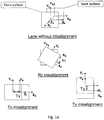
- front and back surface misalignment does not result in an optical error.
- Adding a toric surface to its front surface allows for reduction of the lens distortions. The greater a cylinder value of the toric surface, the higher the lens distortion reduction.
- a misalignment exists between the front and back surfaces of the lens as shown in Fig. 1a , an unwanted astigmatism is produced on the lens.
- FV position far vision diopter measurement position
- Fig. 1a shows that misalignment between the two lens surfaces can be due to translation along the X axis, with a value of Tx, translation along the Y axis, with a value of Ty, and/or rotation around the Z axis, with an angle of Rz.
- the finished lens has an astigmatism tolerance of 0.12D. This requirement must be met after all the potential sources of error have been taken into account. Misalignment is just one such potential source of error. In a conventional laboratory for manufacturing progressive lenses, the alignment accuracy is difficult to minimize without significantly modifying the conventional lens finishing process. As a result, yields for final lenses are significantly reduced when using a front toric surface.
- a tore of 1.0D just from the RZ misalignment error due to the manufacturing process with use of the standard equipment, the astigmatism tolerance of 0.12D can be exceeded. If the tore is reduced to 0.75D, some margin exists to accommodate other potential sources of error, but the margin is quite small and, actually, is insufficient. The margin increases as the tore is further reduced to lower values. However, lower values of tore do not provide adequate lens distortion compensation. Thus, a progressive lens design is required that can accommodate the misalignment tolerances of a standard lab, provides the desired level of distortion compensation, and yet leaves a sufficient margin for other potential sources of error without exceeding the 0.12D permitted tolerance for a finished lens.
- One object of the present invention is to alleviate at least partly the above mentioned drawbacks.
- the invention aims to improve the comfort of wearing an ophthalmic lens for the wearer for whom the lens is intended by improving the performance of the lens relative to image deformation, i.e. distortion, while providing a good sharpness.
- the invention relates to a method for manufacturing a semi-finished lens blank having a near vision area and a far vision area, and a main meridian separating the lens into a nasal area and a temporal area, the method comprising:
- Another aspect of the invention also relates to a computer program product comprising one or more stored sequence of instruction that is accessible to a processor and which, when executed by the processor, causes the processor to carry out the steps of a method according to an embodiment of the invention.
- Another aspect of the invention also relates to a computer readable medium carrying out one or more sequences of instructions of the computer program product according to an embodiment of the invention, the one or more sequences causing a processor to carry out the steps of the method of claim 1.
- a method according to claim 1 is proposed. This method enables an improved distortion without degrading the performance in term of correction of the optical power and astigmatism. This results in an increased comfort for the wearer.
- a progressive lens comprises at least one but preferably two non-rotationally symmetrical aspheric surfaces, for instance but not limited to, progressive surface, regressive surface, toric or atoric surfaces.
- the local minimum radius of curvature R min and the local maximum radius of curvature R max are the same and, accordingly, the minimum and maximum curvatures CURV min and CURV max are also identical.
- the local minimum radius of curvature R min and the local maximum radius of curvature R max are different.
- the minimum and maximum spheres labeled SPH min and SPH max can be deduced according to the kind of surface considered.
- any aspherical face of the lens may be expressed by the local mean spheres and cylinders.
- a surface can be considered as locally aspherical when the cylinder is at least 0.25 diopters.
- a local cylinder axis ⁇ AX may further be defined.
- Figure 2 illustrates the astigmatism axis ⁇ as defined in the TABO convention and figure 3 illustrates the cylinder axis ⁇ AX in a convention defined to characterize an aspherical surface.
- the cylinder axis ⁇ AX is the angle of the orientation of the maximum curvature CURV max with relation to a reference axis and in the chosen sense of rotation.
- the reference axis is horizontal (the angle of this reference axis is 0°) and the sense of rotation is counterclockwise for each eye, when looking at the wearer (0° ⁇ AX ⁇ 180°).
- An axis value for the cylinder axis ⁇ AX of +45° therefore represents an axis oriented obliquely, which when looking at the wearer, extends from the quadrant located up on the right to the quadrant located down on the left.
- Gauss formula enables to express the local sphere SPH along any axis ⁇ , ⁇ being a given angle in the referential defined in figure 3 .
- the axis ⁇ is shown in Figure 4 .
- SPH ⁇ SP H max cos 2 ⁇ ⁇ ⁇ AX + SP H min sin 2 ⁇ ⁇ ⁇ AX
- the Gauss formula can also be expressed in term of curvature so that the curvature CURV along each axis forming an angle ⁇ with the horizontal axis by:
- CURV ⁇ CUR V max cos 2 ⁇ ⁇ ⁇ AX + CUR V min sin 2 ⁇ ⁇ ⁇ AX
- a surface may thus be locally defined by a triplet constituted by the maximum sphere SPH max , the minimum sphere SPH min and the cylinder axis ⁇ AX .
- the triplet may be constituted by the mean sphere SPH mean , the cylinder CYL and the cylinder axis ⁇ AX .
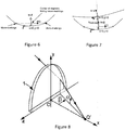
- a referential is defined with respect to micro-markings as illustrated in figures 6 and 7 , for a surface bearing micro-markings and for a surface not bearing the micro-markings respectively.
- Progressive lenses comprise micro-markings that have been made mandatory by a harmonized standard ISO 8990-2.
- Temporary markings may also be applied on the surface of the lens, indicating diopter measurement positions (sometimes referred to as control points) on the lens, such as for far vision and for near vision, a prism reference point and a fitting cross for instance, as represented schematically in figure 45 .
- far vision diopter measurement position FV position
- NV position near vision diopter measurement position
- micro-markings also make it possible to define referential for both surfaces of the lens.
- Figure 6 shows the referential for the surface bearing the micro-markings.
- MG is the collinear unitary vector defined by the two micro-markings.
- vector Y of the referential is equal to the vector product of Z by MG;
- vector X of the referential is equal to the vector product of Y by Z. ⁇ X, Y, Z ⁇ thereby form a direct orthonormal trihedral.
- the X axis is the horizontal axis and the Y axis is the vertical axis as it shown in Figure 3 .
- Figure 7 shows the referential for the surface opposite to the surface bearing the micro-markings.
- Referential of the second surface is constructed the same way as the referential of the first surface, i.e. vector Z is equal to the unitary normal of the second surface; vector Y is equal to the vector product of Z by MG; vector X is equal to the vector product of Y by Z.
- the X axis is the horizontal axis and the Y axis is the vertical axis as it shown in Figure 3 .
- a progressive multifocal lens may also be defined by optical characteristics, taking into consideration the situation of the person wearing the lenses.
- Figures 8 and 9 are diagrammatic illustrations of optical systems of eye and lens, thus showing the definitions used in the description. More precisely, figure 8 represents a perspective view of such a system illustrating parameters ⁇ and ⁇ used to define a gaze direction. Figure 9 is a view in the vertical plane parallel to the antero-posterior axis of the wearer's head and passing through the center of rotation of the eye in the case when the parameter ⁇ is equal to 0.
- the center of rotation of the eye is labeled Q'.
- the axis Q'F' shown on Figure 9 in a dot-dash line, is the horizontal axis passing through the center of rotation of the eye and extending in front of the wearer - that is the axis Q'F' corresponding to the primary gaze view.
- This axis cuts the aspherical surface of the lens on a point called the fitting cross, which is present on lenses to enable the positioning of lenses in a frame by an optician.
- the point of intersection of the rear surface of the lens and the axis Q'F' is the point O. O can be the fitting cross if it is located on the rear surface.
- An apex sphere, of center Q', and of radius q', is tangential to the rear surface of the lens in a point of the horizontal axis.
- a value of radius q' of 25.5 mm corresponds to a usual value and provides satisfying results when wearing the lenses.
- a given gaze direction - represented by a solid line on figure 8 - corresponds to a position of the eye in rotation around Q' and to a point J of the apex sphere; the angle ⁇ is the angle formed between the axis Q'F' and the projection of the straight line Q'J on the horizontal plane comprising the axis Q'F'; this angle appears on the scheme on Figure 8 .
- the angle ⁇ is the angle formed between the axis Q'J and the projection of the straight line Q'J on the horizontal plane comprising the axis Q'F'; this angle appears on the scheme on Figures 8 and 9 .
- a given gaze view thus corresponds to a point J of the apex sphere or to a couple ( ⁇ , ⁇ ). The more the value of the lowering gaze angle is positive, the more the gaze is lowering and the more the value is negative, the more the gaze is rising.
- the image of a point M in the object space, located at a given object distance, is formed between two points S and T corresponding to minimum and maximum distances JS and JT, which would be the sagittal and tangential local focal lengths.
- the image of a point in the object space at infinity is formed, at the point F'.
- the distance D corresponds to the rear frontal plane of the lens.
- Ergorama is a function associating to each gaze direction the usual distance of an object point. Typically, in far vision following the primary gaze direction, the object point is at infinity. In near vision, following a gaze direction essentially corresponding to an angle ⁇ of the order of 35° and to an angle ⁇ of the order of 5° in absolute value toward the nasal side, the object distance is of the order of 30 to 50 cm.
- US patent US-A-6,318,859 may be considered. This document describes an ergorama, its definition and its modeling method. For a method of the invention, points may be at infinity or not. Ergorama may be a function of the wearer's ametropia.
- An object point M at an object distance given by the ergorama is considered for a gaze direction ( ⁇ , ⁇ ).
- the object proximity can be considered as the inverse of the distance between the object point and the front surface of the lens, on the corresponding light ray.
- This definition corresponds to the astigmatism of a ray beam created by the lens. It can be noticed that the definition gives, in the primary gaze direction, the classical value of astigmatism.
- the astigmatism angle is the angle ⁇ .
- the angle ⁇ is measured in the frame ⁇ Q', x m , y m , z m ⁇ linked to the eye. It corresponds to the angle with which the image S or T is formed depending on the convention used with relation to the direction z m in the plane ⁇ Q', z m , y m ⁇ .
- the pantoscopic angle is the angle in the vertical plane between the optical axis of the spectacle lens and the visual axis of the eye in the primary position, usually taken to be the horizontal.
- the wrap angle is the angle in the horizontal plane between the optical axis of the spectacle lens and the visual axis of the eye in the primary position, usually taken to be the horizontal.
- Other conditions may be used. Wearing conditions may be calculated from a ray-tracing program, for a given lens. Further, the optical power and the astigmatism may be calculated so that the prescription is either fulfilled at the reference points (i.e control points in far vision) and for a wearer wearing his spectacles in the wearing conditions or measured by a frontofocometer.
- Figure 10 represents a perspective view of a configuration wherein the parameters ⁇ and ⁇ are non zero.
- the effect of rotation of the eye can thus be illustrated by showing a fixed frame ⁇ x, y, z ⁇ and a frame ⁇ x m , y m , z m ⁇ linked to the eye.
- Frame ⁇ x, y, z ⁇ has its origin at the point Q'.
- the axis x is the axis Q'O and it is oriented from the lens toward the eye.
- the y axis is vertical and oriented upwardly.
- the z axis is such that the frame ⁇ x, y, z ⁇ be orthonormal and direct.
- the frame ⁇ x m , y m , z m ⁇ is linked to the eye and its center is the point Q'.
- the x m axis corresponds to the gaze direction JQ'.
- the two frames ⁇ x, y, z ⁇ and ⁇ x m , y m , z m ⁇ are the same.
- a surface characterization is thus equivalent to an optical characterization. In the case of a blank, only a surface characterization may be used. It has to be understood that an optical characterization requires that the lens has been machined to the wearer's prescription.
- the characterization may be of a surface or optical kind, both characterizations enabling to describe the same object from two different points of view.
- the characterization of the lens refers to the ergorama-eye-lens system described above.
- the term 'lens' is used in the description but it has to be understood as the 'ergorama-eye-lens system'.
- the value in surface terms can be expressed with relation to points. The points are located with the help of abscissa or ordinate in a frame as defined above with respect to figures 3 , 6 and 7 .
- Gaze directions are usually given by their degree of lowering and azimuth in a frame whose origin is the center of rotation of the eye.
- a point called the fitting cross is placed before the pupil or before the eye rotation center Q' of the eye for a primary gaze direction.
- the primary gaze direction corresponds to the situation where a wearer is looking straight ahead.
- the fitting cross corresponds thus to a lowering angle ⁇ of 0° and an azimuth angle ⁇ of 0° whatever surface of the lens the fitting cross is positioned - rear surface or front surface.
- the "upper" part of the surface of a lens - or of a semi-finished lens blank - corresponds to a positive value along the y axis, and preferably to a value along the y axis superior to the y_value at the fitting cross and the "lower" part of the surface of a lens - or of a semi-finished lens blank - corresponds to a negative value along the y axis in the frame as defined above with respect to figures 3 , 6 and 7 , and preferably to a value along the y axis inferior to the y_value at the fitting cross.
- the visual field zones seen through a lens are schematically illustrated in figures 14 and 15 .
- the lens comprises a far vision zone 26 located in the upper part of the lens, a near vision zone 28 located in the lower part of the lens and an intermediate zone 30 situated in the lower part of the lens between the far vision zone 26 and the near vision zone 28.
- the lens also has a main meridian 32 passing through the three zones and defining a nasal side and a temporal side.
- all the gaze directions defined in that way form the meridian line of the ergorama-eye-lens system.
- the meridian line of the lens represents the locus of mean gaze directions of a wearer when he is looking from far to near visions.
- the meridian line 32 of a surface of the lens is defined as follows: each gaze direction ( ⁇ , ⁇ ) belonging to the optical meridian line of the lens intersects the surface at a point (x, y).
- the meridian line of the surface is the set of points corresponding to the gaze directions of the meridian line of the lens.
- the meridian 32 separates the lens into a nasal area and a temporal area.
- the nasal area is the area of the lens which is between the meridian and the nose of the wearer whereas the temporal area is the area which is between the meridian and the temple of the wearer.
- the nasal area is labeled Area_nasal and the temporal area is labeled Area_temporal, as it will in the remainder of the description.
- Distortion is a defect which is not related to the resolution of images impacting the sharpness or the contrast of the image formed by the periphery of the visual field of the lens but merely to their shape.
- "barrel” distortion occurs with minus lenses whereas "pin-cushion” distortion occurs with plus lenses; these are inherent in the optical characteristics of simple plus or minus lenses. Distortion can be evaluated in different situations of use of the lens.
- FIG. 11 illustrates the effect of distortion along a ray seen by a viewer in his peripheral field of vision after passing through a lens.
- point A in central vision
- point B peripheral points
- the angle ⁇ is a quantitative way of expressing the prismatic deviation which gives to the wearer the illusion that point B is located at point B'.
- figure 12 we can quantify how a vertical and/or a horizontal line of an object grid seen in the peripheral vision as being curved, as shown in figure 12 .
- the grid (solid lines) seen without the lens and which is not deformed is superimposed with the distorted grid (broken lines) seen through the lens. Therefore, it becomes apparent that the distortion has an impact on peripheral vision.
- the distortion can be quantified by calculating how a peripheral square is deformed. For this calculation, figure 13 is an enlarged view of one square of the grid seen without the lens over which is superimposed the deformed square of the deformed grid seen through the lens. The square has two diagonals whose lengths are labeled a.
- the corresponding deformed square has two diagonals whose lengths are different and are respectively labeled b and c, b corresponding to a diagonal longer than c.
- b/c is different from 1. The more this ratio is greater than 1, the greater is the distortion in this area of the lens. Calculating the ratio of the diagonal is thus a way of quantifying distortion.
- Distortion can also be evaluated considering that the eye is moving behind the lens and this kind of distortion is named dynamic distortion. It appears in the periphery of the central visual field and it is evaluated in central vision (named also direct vision).
- distortion can be evaluated in static vision, i.e. the direction of gaze is fixed and distortion is analyzed in peripheral vision.
- Distortion can also be evaluated in dynamic vision, i.e. the direction of gaze is free and distortion is analyzed in central vision. Evaluation in static or dynamic vision is made depending on the intended use of the lens.
- Figure 11 illustrates distortion in static vision.
- the quantities analyzed would be different - magnification in peripheral or central vision respectively - but the conclusions remain the same, i.e. magnification variations must be mastered.
- the optical mean power in central vision increases when lowering the gaze direction (or for when lowering the peripheral ray direction) from the upper part of the lens to the lower part of the lens.
- This effect is due to the fact that to suit the presbyopic wearer needs, the optical power between the far and near visions of the multifocal lens is increasing.
- the expression 'upper/lower parts of the lens' means the upper/lower parts of the central or peripheral field of view depending on whether static vision or dynamic vision is considered.
- mean central or peripheral magnifications of the eye-lens system also increases when lowering the gaze or peripheral ray direction from the central or peripheral far vision zone to the central or peripheral near vision zone since mean magnification is, at least at first order, proportional to mean power.
- a way of reducing distortion is thus to minimize the difference in mean central or peripheral magnification between the far vision zone and the near vision zone.
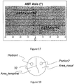
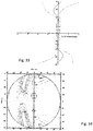
- Figure 16 is a schematic view of the mean orientation of the astigmatism axis of the lens, the mean value being calculated in the lower part of the lens for a lowering gaze direction equal to 25°.
- Figure 17 corresponds to the variation of the axis of the resulting astigmatism evaluated in central vision as a function of azimuth angle ⁇ for a given fixed lowering angle ⁇ 1 as it is shown in Figure 16 .
- the residual astigmatism axes are nearly constant for all given gaze direction ( ⁇ 1 , ⁇ ).
- ⁇ 1 , ⁇ For example, for the selected lens, and for ⁇ 1 , on the temporal side, the axis of resulting astigmatism is about 150° and on the nasal side, it is about 40°.
- Residual astigmatism can be evaluated, such as mean power, in peripheral vision or in central vision. Residual astigmatism is the astigmatism defect that means the astigmatism that is not required to correct the wearer's vision.
- the astigmatism value is the difference between the minimal optical power (optical power along the axis of astigmatism) and the maximal optical power (optical power along the counter axis of astigmatism, the counter axis being defined as equal to the axis of astigmatism + 90°), thereby resulting in difference in magnification between the two axes (the axis and the counter axis).
- Another way of reducing distortion is thus to minimize the difference in central or peripheral magnification between these two axes for each gaze direction
- Figure 18 illustrates a flowchart of an example of the method according to the invention for determining a progressive ophthalmic lens.
- the method comprises the step 10 of choosing a target optical function ("TOF") suited to the wearer.
- TOF target optical function
- TOF target optical function
- to improve the optical performances of an ophthalmic lens methods for optimizing the parameters of the ophthalmic lens are thus used. Such optimization methods are designed so as to get the optical function of the ophthalmic lens as close as possible to a predetermined target optical function.
- the target optical function represents the optical characteristics the ophthalmic lens should have.
- target optical function of the lens is used for convenience. This use is not strictly correct in so far as a target optical function has only a sense for a wearer - ophthalmic lens and ergorama system.
- the optical target function of such system is a set of optical criteria defined for given gaze directions. This means that an evaluation of an optical criterion for one gaze direction gives an optical criterion value.
- the set of optical criteria values obtained is the target optical function.
- the target optical function then represents the performance to be reached.
- optical criteria such as optical power or astigmatism; however, more elaborate criteria may be used such as mean power which is a linear combination of optical power and astigmatism.
- Optical criteria involving aberrations of higher order may be considered.
- the number of criteria N considered depends on the precision desired. Indeed, the more criteria considered, the more the lens obtained is likely to satisfy the wearer's needs. However, increasing the number N of criteria may result in increasing the time taken for calculation and the complexity to the optimization problem to be solved. The choice of the number N of criteria considered will then be a trade-off between these two requirements. More details about target optical functions, optical criteria definition and optical criteria evaluation can be found in patent application EP-A-2207 118 .
- the method also comprises a step 12 of defining a first aspherical surface of the lens and a second aspherical surface of the lens.
- the first surface is an object side (or front) surface and the second surface is an eyeball side (or back) surface.
- Each surface has in each point a mean sphere value SPH mean , a cylinder value CYL and a cylinder axis ⁇ AX .
- the method further encompasses a step 14 of defining at least one first portion Portion1 in the temporal area and/or at least one second portion Portion2 in the nasal area. Therefore, Portion1 is included in Area_temporal and Portion2 is included in Area_nasal.
- FIG 19 Examples of choice of these portions Portion1 and Portion2 are illustrated in figure 19 .
- the portions are discs which are symmetrical with respect to the meridian 32 of the lens.
- Those optical zones Portion1 and Portion2 have corresponding portions on the front surface of the lens.
- Each gaze direction delimiting the optical portions intersects the first aspherical surface (the front surface) so as to define corresponding portions on the front surface Portion1_Front_Surface and Portion2_Front_Surface.
- portions Portion1 and Portion2 in the temporal area and in the nasal area may be defined on the lens as follows: When central vision is considered, Portion1 in the temporal area may be delimited by gaze directions of 0° ⁇ 30° and -40° ⁇ -5° and such that resulting astigmatism in the portion considered is more than 0.50 diopters. Portion2 in the nasal area may be delimited by gaze directions of 0° ⁇ 30° and 5° ⁇ 40° and such that resulting astigmatism in the portion considered is more than 0.50 diopters.
- Portion1 in the temporal area may be further delimited by gaze directions of 5° ⁇ 30° and -30° ⁇ -10° and such that resulting astigmatism in the portion considered is more than 0.50 diopters.
- Portion2 in the nasal area may be further delimited by gaze directions of 5° ⁇ 30° and 10° ⁇ 30° and such that resulting astigmatism in the portion considered is more than 0.50 diopters.
- Portion1 in the temporal area may be delimited by ray directions of 0° ⁇ 50° and -50° ⁇ -10° and such that resulting astigmatism in the portion considered is more than 0.50 diopters.
- Portion2 in the nasal area may be delimited by ray directions of 0° ⁇ 50° and 10° ⁇ 50° and such that resulting astigmatism in the portion considered is more than 0.50 diopters.
- Portion1 in the temporal area may be further delimited by ray directions of 10° ⁇ 50° and -40° ⁇ -20° and such that resulting astigmatism in the portion considered is more than 0.50 diopters.
- Portion2 in the nasal area may be further delimited by ray directions of 10° ⁇ 50° and 20° ⁇ 40° and such that resulting astigmatism in the portion considered is more than 0.50 diopters.
- Portion1 in the temporal area may be delimited by ray directions of -20° ⁇ 20° and -50° ⁇ -10° and such that resulting astigmatism in the portion considered is more than 0.50 diopters.
- Portion2 in the nasal area may be delimited by ray directions of -20° ⁇ 20° and 10° ⁇ 50° and such that resulting astigmatism in the portion considered is more than 0.50 diopters.
- Portion1 in the temporal area may be further delimited by ray directions of -20° ⁇ 20 and -40° ⁇ -20° and such that resulting astigmatism in the portion considered is more than 0.50 diopters.
- Portion2 in the nasal area may be further delimited by ray directions of -20° ⁇ 20 and 20° ⁇ 40° and such that resulting astigmatism in the portion considered is more than 0.50 diopters.
- portions Portion1 and Portion2 may be further reduced.
- portions Portion1 and Portion2 are defined as the projection of the above defined portions on the surface.
- Portion1 shown as a box outlined with dot-dash lines and separated into sections P1 and P3
- Portion1 could be delimited on the front surface by -20mm ⁇ x ⁇ -2.5mm and 4>y>-11mm
- Portion2 (not shown) could be delimited on the front surface by 2.5mm ⁇ x ⁇ 20mm and 4>y>-11mm.
- Portion1 could be further delimited on the front surface by -15mm ⁇ x ⁇ -5mm and 0>y>-11mm (shown as a box outlined with dash lines and separated into sections P2 and P4), and Portion2 (not shown) could be further delimited on the front surface by 5mm ⁇ x ⁇ 15mm and 0>y>-11mm.
- the method also comprises a determining step 16 to accomplish the following.
- a target optical function suited to the individual wearer is selected.
- the target optical function defines, for each gaze direction when the lens is worn, a refractive power (P ⁇ , ⁇ ), a module of astigmatism (Ast ⁇ , ⁇ ) and an axis of astigmatism ( ⁇ ⁇ , ⁇ ), each gaze direction corresponding to a lowering angle ( ⁇ ) and to an azimuth angle ( ⁇ ).
- the module and axis of astigmatism can refer to the prescribed astigmatism, or the total astigmatism, or the residual astigmatism.
- Each of the first surface and the second surface have in each point a mean sphere value (SPHmean), a cylinder value (CYL) and a cylinder axis ( ⁇ AX ). At least one first portion in the temporal area and at least one second portion in the nasal area are defined. For at least one of the first or the second portion of the first surface a reference axis of astigmatism ⁇ ref being the average axis of astigmatism of the target optical function for gaze directions intersecting the first surface over the considered portion is determined.
- An average cylinder axis value ⁇ defined as the following expression, where N is the total number of points considered in the portion is determined.
- a minimum cylinder axis value Min ⁇ (shown as Min axis P3 on figure 30a ) and a maximum cylinder axis value Max ⁇ (shown as Max axis P3 on figure 30a ) among all the N axis values ⁇ AXi considered are determined.
- the area P3 of the surface considered for this axis evaluation is shown cross-hatched within Portion1 on figures 29a and 30a and, as stated above, each point i therein has a cylinder value greater than 0.25D.
- a differently-sized alternative area P4 is shown on figures 29b and 30b , with its Min axis P4 and Max axis P4.
- a distance value D defined as the distance in mm between the point of the considered portion presenting the minimum axis value and the point of the considered portion presenting the maximum axis value, is determined.
- determining step 16 generates values for the parameters ⁇ , Grad and ⁇ ref .
- the method further comprises a step 18 of modifying the first surface, using the parameters generated in step 16, so that it has the following characteristics.
- step 16 and 18 can apply on portion 1 only, or on portion 2 only, or on both portion 1 and portion 2, each portion having its own ⁇ and Grad values, denoted for example ⁇ 1 and ⁇ 2, Grad1 and Grad2.
- the chart in figure 31 provides illustrative values for the above-mentioned parameters related to the third embodiment shown in figures 41 to 44 .
- the chart in figure 32 provides illustrative values for the above-mentioned parameters related to the first and second embodiments shown in figures 33 to 40 .
- the method further comprises a step 20 of modifying the second aspherical surface so as to reach the target optical function for the lens and guarantee an optimum sharpness for the lens.
- the modifying of the second surface is carried out by optical optimization for minimizing the difference between a current optical function and the target optical function with a cost function.
- a cost function is a mathematical quantity expressing the distance between two optical functions. It can be expressed in different ways according to the optical criteria favored in the optimization. In the sense of the invention, "carrying out an optimization” should preferably be understood as "minimizing" the cost function. Of course, the person skilled in the art will understand that the invention is not limited to a minimization per se.
- the optimization could also be a maximization of a real function, according to the expression of the cost function which is considered by the person skilled in the art. Namely "maximizing" a real function is equivalent to “minimizing” its opposite.
- the lens obtained (such as the one of figure 20 ) thus exhibits reduced distortion properties while guaranteeing the target optical function, the target optical function being defined to provide an optimal sharpness of the image to the wearer.
- Such effect can be qualitatively understood by the fact that the orientations of the curvatures for the first surface are modified which implies that the impact on the magnification of the lens is modified, resulting in a reduced distortion.
- the geometry of the first surface is chosen so that the distortion of the lens is reduced.
- the second surface is determined to ensure optimal optical performances impacting the sharpness of the image.
- Steps 18 and 20 of modifying the first and second surfaces can be carried out by toggling between first and second surfaces with a first target optical function associated to the front surface dedicated to minimizing distortion and a second target optical function associated to the rear surface dedicated to ensuring sharpness of the lens.
- first target optical function associated to the front surface dedicated to minimizing distortion
- second target optical function associated to the rear surface dedicated to ensuring sharpness of the lens.
- the determining step 16 of the method can be carried out in different ways.
- first and/or second reference axes ⁇ 1 and ⁇ 2 may further be determined based on the prescribed astigmatism or the total astigmatism or the residual astigmatism.
- the first and/or second reference axes ⁇ 1 and ⁇ 2 are therefore more relevantly determined, since they are suited to the wearer.
- the axis of total astigmatism is equal to about the axis of prescribed astigmatism.
- the determining step 16 instead of considering mean values of the astigmatism axis for gaze directions belonging to Portion1 and to Portion2 to determine reference axes ⁇ 1 and/or ⁇ 2 , one can consider the local value of astigmatism axis for each direction of gaze intersecting the first surface. Conditions 1 and 2 described above would apply for each point of Portion1 and/or Portion2 when modifying the first surface, each point being the intersection point between the said surface and the gaze direction.
- each respective reference axis ⁇ 1 and/or ⁇ 2 may also be defined by optical optimization that minimizes the distortion over the respective portion Portion1 and Portion2.
- the optimization could also be a maximization of a real function.
- modifying the first and second surfaces can be carried out by toggling between first and second surfaces with a first target optical function that minimizes the distortion over the respective portion Portion1 and Portion2 and a second target optical function ensuring sharpness of the lens. Such toggling between first and second surfaces optimization is described in EP-A-2 207 118 previously mentioned.
- Such embodiment with an optimization minimizing the distortion over the respective portions Portion1 and Portion2 enables to determine the reference axes ⁇ 1 and/or ⁇ 2 that give a lens with the most reduced distortion.
- the optical power P ⁇ , ⁇ ( ⁇ ) of the lens in a given gaze direction ( ⁇ , ⁇ ), along an axis forming an angle ⁇ with the horizontal axis, is the combination of the spheres along this axis of the rear surface and the front surface.
- SPH_front x,y ( ⁇ ) is the sphere of the front face at the intersection point of the gaze direction ( ⁇ , ⁇ ) with the front surface, along the axis ⁇
- SPH_rear x',y' ( ⁇ ) is the sphere of the rear surface at the intersection point of the gaze direction ( ⁇ , ⁇ ) with the rear surface
- Figure 5 is an illustration of this formula for a point of a front surface with a maximum sphere of 7.0 ⁇ , a minimum sphere of 5.0 ⁇ and a cylinder axis ⁇ AX of 65° (curve 22 commented before) and a spherical rear surface (curve 42).
- the optical power P ⁇ , ⁇ ( ⁇ ) (curve 44) of the lens for the gaze direction ( ⁇ , ⁇ ) along the axis is equal to the sum of the sphere of the front surface along the same axis in the corresponding point (x,y) and the sphere of the back surface along the same axis in the corresponding point (x',y'), the corresponding points are the intersection points between the gaze direction ( ⁇ , ⁇ ) and the surfaces.
- G ⁇ , ⁇ ( ⁇ ) is the magnification along the axis forming an angle ⁇ with the horizontal axis
- L is the distance from the eyeball side surface of the lens to the eye rotation center if central vision is considered or L is the distance from the eyeball side surface of the lens to pupil if peripheral vision is considered
- t the thickness of the lens
- n the refractive index of the lens
- FIG. 21 is a representation of such variation for a gaze direction belonging to Portion1 (Temporal Area)
- the axis of astigmatism is ⁇ as explained before.
- the axis of astigmatism is the axis along which the optical power is minimal.
- the maximum optical power is thus along the axis ⁇ +90°. Accordingly, the minimum magnification is G ⁇ , ⁇ ( ⁇ ) and the maximum magnification is G ⁇ , ⁇ ( ⁇ +90°).
- the values of minimal optical power P min and maximal optical power P max are imposed for any gaze direction. They should therefore be considered as constant in the formulas for the quantity DG ⁇ , ⁇ ( ⁇ ).
- the value of the sphere of the front surface along the axis ⁇ and the value of the sphere of the front surface along the axis ⁇ +90° given by the Gauss formula depends on the cylinder axis.
- the value of DG ⁇ , ⁇ ( ⁇ ) depends on the chosen cylinder axis.
- DG ⁇ , ⁇ ( ⁇ ) is a function of ⁇ AX . This function when represented enables to obtain figure 22 .
- the example was carried out with a value of L of 25 mm for the distance from the eyeball side surface of the lens to the eyeball, a value t of 1.4 mm for the thickness of the lens and a value n of 1.665 for the refractive index.
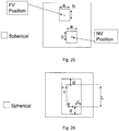
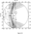
- Fig. 25 shows surface characteristics for a first surface of a lens according to an example embodiment.
- the first surface can be the front surface of a lens.
- a first part of the spherical area includes the FV position and a second part of the spherical area includes the NV position.
- the first part of the spherical area including the FV position is separate from, i.e., not connected on the first surface of the lens, the second part of the spherical area including the NV position .
- a size of each of the first and second part of the spherical area is defined by a reference distance (width) 'a' and a reference distance (height) 'b', the FV or NV position being centered at its respective part of the spherical area defined by the reference distance 'a' and the reference distance 'b'.
- the reference distance 'a' is preferably set to be greater than two times the misalignment error (Tx) in the X axis (horizontal axis) direction of the lens due to the manufacturing process, and the reference distance 'b' is set to be greater than two times the misalignment error (Ty) in the Y axis (vertical axis) direction of the lens due to the manufacturing process.
- the reference distance 'a' is greater than two times the misalignment error (Tx) in the X axis (horizontal axis) direction of the lens
- the reference distance 'b' is greater than two times the misalignment error (Ty) in the Y axis (vertical axis) direction of the lens.
- the toric or cylinder area (cylinder > 0.25D) is formed on the first surface outside the above-described first and second parts constituting the spherical area.
- Fig. 26 shows surface characteristics for a first surface of a lens according to another example embodiment.
- a spherical area of the lens which has a substantially constant sphere value, includes the FV position and the NV position of an individual wearer, as well as the meridian therebetween.
- An inset 'e' defines a distance in the X axis (horizontal axis) direction between the FV position and the NV position of the individual wearer.
- a length 'L' defines a distance in the Y axis (vertical axis) direction between the FV position and the NV position of the individual wearer.
- a reference distance 'c' defines a distance that the spherical area extends in the X axis (horizontal axis) from the FV position toward the temporal edge of the lens
- a reference distance 'd' defines a distance that the spherical area extends in the Y axis (vertical axis) direction from the FV position toward the top edge of the lens.
- the reference distance 'c' defines a distance that the spherical area extends in the X axis (horizontal axis) from the NV position toward the nasal edge of the lens
- the reference distance 'd' defines a distance that the spherical area extends in the Y axis (vertical axis) direction from the NV position toward the bottom edge of the lens.
- the reference distance 'c' is greater than the misalignment error (Tx) in the X axis (horizontal axis) direction of the lens.
- the reference distance 'd' is greater than the misalignment error (Ty) in the Y axis (vertical axis) direction of the lens.
- the size of the spherical area is thus defined by the inset 'e', the length 'L' and the reference distances 'c' and 'd' from each of the FV position and the NV position .
- the toric or cylinder area is formed on the first surface of the lens outside the spherical area.
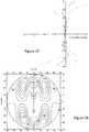
- Fig. 27 shows surface characteristics for a first surface of a lens according to still another example embodiment.
- a main spherical area of the lens which has a substantially constant sphere value, includes the FV position and the NV position of an individual wearer, and the meridian therebetween, as in the embodiment of Fig. 26 .
- first and second extensions into the nasal and temporal areas can be provided in the FV area of the lens.
- the size of the main spherical area may be defined by the inset 'e', the length 'L' and the references 'c' and 'd' from each of the FV position and the NV position. Sizes of the first extension and the second extension may each be defined by the reference distances 'g' and 'f'.
- the first extension of the spherical area extends in the temporal area in the FV area of the lens from a main area of the spherical area by a distance 'f' in the X axis (horizontal axis) direction from an edge of the main spherical area defined by the reference distance 'c' at the FV position toward the temporal edge of the lens.
- the first extension of the spherical area extends in the temporal area in the FV area of the lens by a distance 'g' in the Y axis (vertical axis) direction from a top of the main spherical area defined by the reference distance 'd' at the FV position toward the bottom of the lens.
- the second extension of the spherical area extends in the nasal area in the FV area of the lens by a distance 'f' in the X axis (horizontal axis) direction from an edge of the main spherical area defined by the inset distance 'e' added to the reference distance 'c' at the FV position toward a nasal edge of the lens.
- the second extension of the spherical area extends in the nasal area in the FV area of the lens by a distance 'g' in the Y axis (vertical axis) direction from a top of the main spherical area defined by the reference distance 'd' at the FV position toward the bottom of the lens.
- the second extension of the spherical area is thus defined in the nasal area of the FV area of the lens.
- the reference distance 'c' is greater than the misalignment error (Tx) in the X axis (horizontal axis) direction of the lens.
- the reference distance 'd' is greater than the misalignment error (Ty) in the Y axis (vertical axis) direction of the lens.
- the reference distance 'f' is greater than 5 mm.
- the reference distance 'g' is greater than 5 mm.
- the toric or cylinder area is formed on the first surface outside the main spherical area and the first and second extensions of the main spherical area.
- Fig. 28 shows surface characteristics for a first surface of a lens according to a further example embodiment.
- the first surface has a main spherical area of the lens, which has a substantially constant sphere value and includes the FV position and the NV position of an individual wearer, and the meridian therebetween. Also included are the first and second extensions into the nasal and temporal areas in the FV area of the lens. So far, this embodiment is as shown in Fig. 27 .
- Fig. 28 includes third and fourth extensions into the nasal and temporal areas in the NV area of the lens.
- the size of the main spherical area and the first and second extensions may be defined as described above in connection with Fig. 27 .
- the area of the third and fourth extensions into the nasal and temporal area in the NV area of the lens is defined by the reference distances 'i' and 'h'.
- the third extension of the spherical area extends into the temporal area in the NV area of the lens by a distance 'h' in the X axis (horizontal axis) direction from an edge of the main spherical area defined by the inset distance 'e' and the reference distance 'c' from the FV position toward a temporal edge of the lens.
- the third extension of the spherical area extends in the temporal area in the NV area of the lens by a distance 'i' in the Y axis (vertical axis) direction from a bottom of the main spherical area defined by the reference distance 'd' from the NV position.
- the third extension area of the main spherical area is thus defined in the temporal area of the NV area of the lens.
- the fourth extension of the spherical area extends into the nasal area in the NV area of the lens by a distance 'h' in the X axis (horizontal axis) direction from an edge of the main spherical area defined by the reference distance 'c' toward a nasal edge of the lens.
- the fourth extension of the spherical area extends in the nasal area in the NV area of the lens by the distance 'i' in the Y axis (vertical axis) direction from the bottom of the main spherical area defined by the reference distance 'd' from the NV position.
- a fourth extension area of the main spherical area is thus defined in the nasal area of the NV area of the lens.
- the reference distance 'h' is greater than 2 mm.
- the reference distance 'i' is greater than 5 mm.
- the toric or cylinder area is formed on the first surface outside the spherical area including between the first and third extensions of the spherical area and between the second and fourth extensions of the spherical area.
- Each one of the lenses previously described may be obtained by the method of determining a progressive ophthalmic lens previously described.
- This method can be implemented on a computer.
- discussions utilizing terms such as “computing”, “calculating” “generating”, or the like refer to the action and/or processes of a computer or computing system, or similar electronic computing device, that manipulate and/or transform data represented as physical, such as electronic, quantities within the computing system's registers and/or memories into other data similarly represented as physical quantities within the computing system's memories, registers or other such information storage, transmission or display devices.
- a computer program product comprising one or more stored sequence of instruction that is accessible to a processor and which, when executed by the processor, causes the processor to carry out the steps of the method is also proposed.
- Such a computer program may be stored in a computer readable storage medium, such as, but is not limited to, any type of disk including floppy disks, optical disks, CD-ROMs, magnetic-optical disks, read-only memories (ROMs), random access memories (RAMs) electrically programmable read-only memories (EPROMs), electrically erasable and programmable read only memories (EEPROMs), magnetic or optical cards, or any other type of media suitable for storing electronic instructions, and capable of being coupled to a computer system bus.
- a computer-readable medium carrying one or more sequences of instructions of the computer program product is thus proposed. This enables to carry out the method in any location.
- this set of data may comprise only the first surface of a lens determined according to the method.
- This set of data may preferably further comprise data relating to the eyes of the wearer such that with this set, the progressive ophthalmic lens can be manufactured.
- FIG. 23 represents an apparatus 333 for receiving numerical data. It comprises a keyboard 88, a display 104, an external information center 86, a receiver of data 102, linked to an input/ouput device 98 of an apparatus for data processing 100 which is realized there as a logic unit.
- the apparatus for data processing 100 comprises, linked between them by a data and address bus 92:
- semi-finished ophthalmic lens blanks can be provided by a lens manufacturer to the prescription labs.
- a semi-finished ophthalmic lens blank comprises a first surface corresponding to an optical reference surface, for example a progressive surface in the case of progressive addition lenses, and a second unfinished surface.
- a semi-finished lens blank having suitable optical characteristics, is selected based on the wearer prescription.
- the unfinished surface is finally machined and polished by the prescription lab so as to obtain a surface complying with the prescription. An ophthalmic lens complying with the prescription is thus obtained.
- semi-finished lens blanks can be provided with a first surface meeting the conditions previously described with reference to the first surface of a progressive ophthalmic lens.
- a target optical function must be chosen for each set of prescriptions (similarly to step 10 in figure 18 ).
- a first aspherical surface and a second unfinished surface are defined (similarly to step 12 in figure 18 ).
- At least one reference axis ⁇ 1 or ⁇ 2 is determined not only based on the mean axis of astigmatism ⁇ T and ⁇ N of the target optical function for gaze directions belonging to Portion1 and Portion2 but also on mean axis of astigmatism for lenses of the set of prescriptions.
- the first aspherical surface of the semi-finished lens blank is then modified to meet some conditions.
- the method according to figure 24 is an example.
- the method for manufacturing comprises a step 74 of providing data relating to the eyes of the wearer at a first location. The data are transmitted from the first location to a second location at the step 76 of the method. The progressive ophthalmic lens is then determined at step 78 at the second location according to the method for determining previously described.
- the method for manufacturing further comprises a step 80 of transmitting relative to the first surface to the first location.
- the method also comprises a step 82 of carrying out an optical optimization based on the data relative to the first surface transmitted.
- the method further encompasses a step of transmitting 84 the result of the optical optimization to a third location.
- the method further encompasses a step of manufacturing 86 the progressive ophthalmic lens according to the result of the optical optimization.
- Such method of manufacturing makes it possible to obtain a progressive ophthalmic lens with a reduced distortion without degrading the other optical performances of the lens.
- the transmitting steps 76 and 80 can be achieved electronically. This enables to accelerate the method.
- the progressive ophthalmic lens is manufactured more rapidly.
- the first location, the second location and the third location may just be three different systems, one devoted to the collecting of data, one to calculation and the other to manufacturing, the three systems being situated in the same building.
- the three locations may also be three different companies, for instance one being a spectacle seller (optician), one being a laboratory and the other one a lens designer.
- a set of apparatuses for manufacturing a progressive ophthalmic lens, wherein the apparatuses are adapted to carry out the method for manufacturing is also disclosed.
- Figures 33 to 36 depict a first surface of a lens obtained in accordance with a first embodiment of the invention.
- Figures 37 to 40 depict a first surface of a lens obtained in accordance with a second embodiment of the invention.
- Figures 41 to 44 depict a first surface of a lens obtained in accordance with a third embodiment of the invention. It is noted that figures 29 and 30 correspond to figures 43 and 44 , respectively.
Claims (3)
- Verfahren zur Herstellung eines halbfertigen Linsenrohlings mit einem Nahteil und einem Fernteil sowie einem Hauptschnitt, welcher die Linse in einen Nasalbereich und einen Schläfenbereich einteilt, wobei das Verfahren Folgendes umfasst:Bestimmen einer ersten Oberfläche und einer zweiten, unfertigen Oberfläche der halbfertigen Linse;Bestimmen eines sphärischen Bereichs auf der ersten Oberfläche der halbfertigen Linse mit einem im Wesentlichen konstanten Sphärenwert, einschließlich einer Fernsicht-Dioptrienmessposition für den jeweiligen Träger innerhalb des sphärischen Bereichs, wobei die Fernsicht-Dioptrienmessposition ("FV-Position") und eine Nahsicht-Dioptrienmessposition ("NV-Position") für den jeweiligen Träger im Wesentlichen den gleichen mittleren Sphärenwert aufweisen;Bestimmen der ersten Oberfläche zur Verringerung der Verzeichnung einer aus dem halbfertigen Linsenrohling herzustellenden Linse mittels Definition eines torischen Bereichs, der sich außerhalb des sphärischen Bereichs auf der ersten Oberfläche im nasalen und/oder Schläfen-bereich erstreckt, wobei sich Kenngrößen des torischen Bereichs auf den Astigmatismus der Linse beziehen;Definieren einer für einen vorgegebenen Verordnungsbereich bei den jeweiligen Trägern geeigneten optischen Zielfunktion, welche beim Tragen der Linse für jede Blickrichtung eine Brechkraft (Pα,β), ein Astigmatismusmodul (Astα,β) und eine Astigmatismusachse (γα,β) definiert, wobei jede Blickrichtung einem Neigungswinkel (α) und einem Azimutwinkel (β) entspricht und wobei sich der Astigmatismusmodul und die Astigmatismusachse auf den verordneten Astigmatismus oder den Gesamtastigmatismus oder den Restastigmatismus beziehen;wobei die erste Oberfläche der Linse in jedem Punkt einen mittleren Sphärenwert (SPHmean), einen Zylinderwert (CYL) und eine Zylinderachse (γAX) aufweist;Definieren mindestens eines im Schläfenbereich gelegenen ersten Teils (Portion1) mit einer Fläche von mindestens 25 mm2 und mindestens eines im Nasalbereich gelegenen zweiten Teils (Portion2) mit einer Fläche von mindestens 25 mm2;für den ersten Teil (Portion1) und/oder den zweiten Teil (Portion2) der ersten Oberfläche, Bestimmen einer Astigmatismus-Bezugsachse γref; welche die durchschnittliche Astigmatismus-achse der optischen Zielfunktion für Blick-richtungen ist, welche die die erste Oberfläche über einen betreffenden Teil der ersten Oberfläche schneiden;für den ersten Teil (Portion1) und/oder den zweiten Teil (Portion2) der ersten Oberfläche, Bestimmen eines Zylinderachsenwertes γAXi für jeden Punkt i des betreffenden Teils mit einem Zylinderwert größer als 0,25D, wobei γAXi so definiert ist, dass der Sphärenwert (SPH(γAXi) entlang der Zylinderachse γAXi größer ist als der Sphärenwert (SPH(⊥γAXi)) entlang einer zur Zylinderachse γAXi rechtwinkligen Achse (SPH(γAXi) > SPH(⊥γAXi));für den ersten Teil (Portion1) und/oder den zweiten Teil (Portion2) der ersten Oberfläche, Bestimmen eines durchschnittlichen Zylinderachsenwertes Γ, definiert nach der folgenden Formel, in der N die Gesamtzahl der betreffenden Punkte in dem Teil bezeichnet:
 für den ersten Teil (Portion1) und/oder den zweiten Teil (Portion2) der ersten Oberfläche, Bestimmen eines kleinsten Zylinderachsenwertes MinΓ und eines größten Zylinderachsenwertes MaxΓ von allen betreffenden N Achsenwerten γAXi;für den ersten Teil (Portion1) und/oder den zweiten Teil (Portion2) der ersten Oberfläche, Bestimmen eines Abstandswertes D, definiert als Abstand in mm zwischen dem Punkt des betreffenden Teils mit dem kleinsten Achsenwert und dem Punkt des betreffenden Teils mit dem größten Achsenwert;für den ersten Teil (Portion1) und/oder den zweiten Teil (Portion2) der ersten Oberfläche, Bestimmen eines Gradientenwertes (Grad) der Zylinderachse nach der folgenden Formel:
 Modifizieren der ersten Oberfläche derart, dass auf dem ersten und/oder dem zweiten Teil folgende Bedingungen zutreffen:- Bedingung 1: Der für den betreffenden mindestens einen Teil bestimmte durchschnittliche Zylinderachsenwert Γ beträgt zwischen +20° und -20° der Astigmatismus-Bezugsachse γref für diesen Teil, und- Bedingung 2: Der Gradientenwert (Grad) der für den betreffenden mindestens einen Teil bestimmten Zylinderachse liegt um weniger als 5°/mm über dem betreffenden Teil; undFlächenbearbeitung oder Pressen der ersten Fläche.
 - Computerprogrammprodukt, umfassend eine oder mehrere gespeicherte Befehlssequenzen, welches für einen Prozessor zugreifbar ist und bei Ausführung durch den Prozessor veranlasst, dass der Prozessor die Verfahrensschritte gemäß Anspruch 1 ausführt.
- Maschinenlesbares Medium, welches eine oder mehrere gespeicherte Befehlssequenzen des Computerprogrammprodukts nach Anspruch 2 ausführt, wodurch der Prozessor veranlasst wird, die Verfahrensschritte gemäß Anspruch 1 auszuführen.
Priority Applications (1)
| Application Number | Priority Date | Filing Date | Title |
|---|---|---|---|
| EP13771406.9A EP2893393B1 (de) | 2012-09-07 | 2013-09-06 | Verfahren zur herstellung einer halb-fertigen rohling linse |
Applications Claiming Priority (3)
| Application Number | Priority Date | Filing Date | Title |
|---|---|---|---|
| EP12306083 | 2012-09-07 | ||
| PCT/EP2013/068431 WO2014037482A2 (en) | 2012-09-07 | 2013-09-06 | A method for determining a progressive ophthalmic lens |
| EP13771406.9A EP2893393B1 (de) | 2012-09-07 | 2013-09-06 | Verfahren zur herstellung einer halb-fertigen rohling linse |
Publications (2)
| Publication Number | Publication Date |
|---|---|
| EP2893393A2 EP2893393A2 (de) | 2015-07-15 |
| EP2893393B1 true EP2893393B1 (de) | 2019-07-24 |
Family
ID=46801392
Family Applications (1)
| Application Number | Title | Priority Date | Filing Date |
|---|---|---|---|
| EP13771406.9A Active EP2893393B1 (de) | 2012-09-07 | 2013-09-06 | Verfahren zur herstellung einer halb-fertigen rohling linse |
Country Status (5)
| Country | Link |
|---|---|
| US (1) | US9557578B2 (de) |
| EP (1) | EP2893393B1 (de) |
| CN (1) | CN104620160B (de) |
| BR (1) | BR112015004350B1 (de) |
| WO (1) | WO2014037482A2 (de) |
Families Citing this family (14)
| Publication number | Priority date | Publication date | Assignee | Title |
|---|---|---|---|---|
| WO2014084247A1 (ja) * | 2012-11-28 | 2014-06-05 | Hoya株式会社 | 眼鏡レンズ、眼鏡レンズの製造装置及び製造方法 |
| US10437077B2 (en) | 2014-03-24 | 2019-10-08 | Carl Zeiss Vision Inc. | Method of optimizing geometry of a semi-finished ophthalmic lens in a set of semi-finished ophthalmic lenses |
| EP3006991A1 (de) * | 2014-10-08 | 2016-04-13 | Essilor International (Compagnie Generale D'optique) | Verfahren zur Bestimmung eines Linsenentwurfs einer optischen an einen Träger angepassten Linse |
| US10394052B2 (en) | 2015-03-10 | 2019-08-27 | Essilor International | Method for determining a pair of ophthalmic lenses |
| CN108885356B (zh) * | 2016-04-15 | 2020-06-09 | 依视路国际公司 | 用于向配戴者提供眼科镜片的方法 |
| US10330950B2 (en) * | 2017-02-23 | 2019-06-25 | Indizen Optical Technologies of America, LLC | Progressive lenses with reduced peripheral mean sphere |
| EP3561577A1 (de) * | 2018-04-23 | 2019-10-30 | Essilor International (Compagnie Generale D'optique) | Verfahren zur bestimmung des akzeptanzgrades eines benutzers eines linsenentwurfs |
| USD945876S1 (en) | 2019-04-22 | 2022-03-15 | Fgx International Inc. | Eyeglass display box |
| USD935879S1 (en) | 2019-06-28 | 2021-11-16 | Fgx International, Inc | Eyewear packaging |
| EP4102291A4 (de) * | 2020-02-06 | 2023-11-15 | Nikon-Essilor Co., Ltd. | Empfindlichkeitsbeurteilungsverfahren, brillenglasentwurfsverfahren, brillenglasherstellungsverfahren, brillenglas, brillenglasbestellvorrichtung, vorrichtung zum empfang von brillenglasbestellungen und brillenglasbestell- und bestellempfangssystem |
| US11520308B2 (en) | 2020-07-29 | 2022-12-06 | Indizen Optical Technologies of America, LLC | Progressive lenses with variable reduced peripheral mean sphere |
| USD972407S1 (en) | 2020-10-30 | 2022-12-13 | Fgx International Inc | Eyewear package |
| USD1002248S1 (en) | 2021-01-27 | 2023-10-24 | Fgx International Inc. | Display case |
| US11794975B2 (en) | 2021-06-17 | 2023-10-24 | Fgx International Inc | Eyewear case and packaging system having improved hang tab |
Family Cites Families (14)
| Publication number | Priority date | Publication date | Assignee | Title |
|---|---|---|---|---|
| DE69113127T2 (de) | 1990-06-13 | 1996-03-21 | Seiko Epson Corp | Brillenlinse. |
| EP0597994A4 (en) * | 1991-08-09 | 1994-09-14 | Capricornia Contact Lens | Toric lens with axis mislocation latitude. |
| FR2753805B1 (fr) | 1996-09-20 | 1998-11-13 | Essilor Int | Jeu de lentilles ophtalmiques multifocales progressives |
| FR2783938B1 (fr) | 1998-09-28 | 2000-11-17 | Essilor Int | Lentilles ophtalmiques toriques |
| US6231184B1 (en) * | 1999-11-12 | 2001-05-15 | Johnson & Johnson Vision Care, Inc. | Progressive addition lenses |
| DE10345214B4 (de) * | 2003-09-29 | 2007-09-06 | Rodenstock Gmbh | Serie progressiver Brillengläser mit geringer Divergenz und Rotation des Astigmatismus |
| JP5769914B2 (ja) * | 2006-07-20 | 2015-08-26 | 株式会社ニコン・エシロール | 累進屈折力レンズの設計方法、製造方法および眼鏡レンズの供給システム |
| JP2010520514A (ja) * | 2007-03-07 | 2010-06-10 | ピクセルオプティクス, インコーポレイテッド | 累進光学パワー領域と不連続部を有する多焦点レンズ |
| DE102009053467B4 (de) * | 2008-11-14 | 2018-01-18 | Rodenstock Gmbh | Ophthalmische Linse mit peripherer Brechkraftvariation |
| EP3269296A1 (de) * | 2008-12-01 | 2018-01-17 | Perfect Vision Technology (HK) Ltd. | Verfahren und vorrichtungen zur refraktiven augenkorrektur |
| EP2207118A1 (de) | 2008-12-31 | 2010-07-14 | Essilor International (Compagnie Générale D'Optique) | Verfahren zum Berechnen eines Systems, beispielsweise eines optischen Systems |
| WO2011085936A1 (en) * | 2010-01-18 | 2011-07-21 | Essilor International (Compagnie Generale D'optique) | Process for designing an ophthalmic progressive eyeglass |
| WO2012007064A1 (en) | 2010-07-16 | 2012-01-19 | Carl Zeiss Vision Gmbh | Retardation of progression of refractive error |
| JP5897260B2 (ja) | 2011-02-24 | 2016-03-30 | イーエイチエス レンズ フィリピン インク | 累進屈折力レンズおよびその設計方法 |
-
2013
- 2013-09-06 BR BR112015004350-0A patent/BR112015004350B1/pt active IP Right Grant
- 2013-09-06 US US14/426,441 patent/US9557578B2/en active Active
- 2013-09-06 EP EP13771406.9A patent/EP2893393B1/de active Active
- 2013-09-06 WO PCT/EP2013/068431 patent/WO2014037482A2/en active Application Filing
- 2013-09-06 CN CN201380046523.3A patent/CN104620160B/zh active Active
Non-Patent Citations (1)
| Title |
|---|
| None * |
Also Published As
| Publication number | Publication date |
|---|---|
| CN104620160A (zh) | 2015-05-13 |
| BR112015004350B1 (pt) | 2022-06-07 |
| CN104620160B (zh) | 2016-09-07 |
| WO2014037482A2 (en) | 2014-03-13 |
| WO2014037482A3 (en) | 2014-06-26 |
| US9557578B2 (en) | 2017-01-31 |
| BR112015004350A8 (pt) | 2018-08-14 |
| US20150219924A1 (en) | 2015-08-06 |
| BR112015004350A2 (pt) | 2017-07-04 |
| EP2893393A2 (de) | 2015-07-15 |
Similar Documents
| Publication | Publication Date | Title |
|---|---|---|
| EP2893393B1 (de) | Verfahren zur herstellung einer halb-fertigen rohling linse | |
| EP2780758B1 (de) | Verfahren zur bestimmung eines brillenglases | |
| EP2684094B1 (de) | Verfahren zur definition einer gleitsichtlinse | |
| EP2676165B1 (de) | Eine methode zur bestimmung optischer ziel-funktionen | |
| US9307899B2 (en) | Process for determining a pair of progressive ophthalmic lenses | |
| US9411170B2 (en) | Process for determining a pair of progressive ophthalmic lenses | |
| US20150331254A1 (en) | Multifocal ophthalmic lens |
Legal Events
| Date | Code | Title | Description |
|---|---|---|---|
| PUAI | Public reference made under article 153(3) epc to a published international application that has entered the european phase |
Free format text: ORIGINAL CODE: 0009012 |
|
| 17P | Request for examination filed |
Effective date: 20150330 |
|
| AK | Designated contracting states |
Kind code of ref document: A2 Designated state(s): AL AT BE BG CH CY CZ DE DK EE ES FI FR GB GR HR HU IE IS IT LI LT LU LV MC MK MT NL NO PL PT RO RS SE SI SK SM TR |
|
| AX | Request for extension of the european patent |
Extension state: BA ME |
|
| DAX | Request for extension of the european patent (deleted) | ||
| RAP1 | Party data changed (applicant data changed or rights of an application transferred) |
Owner name: ESSILOR INTERNATIONAL |
|
| GRAP | Despatch of communication of intention to grant a patent |
Free format text: ORIGINAL CODE: EPIDOSNIGR1 |
|
| STAA | Information on the status of an ep patent application or granted ep patent |
Free format text: STATUS: GRANT OF PATENT IS INTENDED |
|
| INTG | Intention to grant announced |
Effective date: 20181120 |
|
| GRAS | Grant fee paid |
Free format text: ORIGINAL CODE: EPIDOSNIGR3 |
|
| GRAA | (expected) grant |
Free format text: ORIGINAL CODE: 0009210 |
|
| STAA | Information on the status of an ep patent application or granted ep patent |
Free format text: STATUS: THE PATENT HAS BEEN GRANTED |
|
| AK | Designated contracting states |
Kind code of ref document: B1 Designated state(s): AL AT BE BG CH CY CZ DE DK EE ES FI FR GB GR HR HU IE IS IT LI LT LU LV MC MK MT NL NO PL PT RO RS SE SI SK SM TR |
|
| REG | Reference to a national code |
Ref country code: GB Ref legal event code: FG4D |
|
| REG | Reference to a national code |
Ref country code: CH Ref legal event code: EP |
|
| REG | Reference to a national code |
Ref country code: DE Ref legal event code: R096 Ref document number: 602013058214 Country of ref document: DE |
|
| REG | Reference to a national code |
Ref country code: AT Ref legal event code: REF Ref document number: 1158886 Country of ref document: AT Kind code of ref document: T Effective date: 20190815 |
|
| REG | Reference to a national code |
Ref country code: IE Ref legal event code: FG4D |
|
| REG | Reference to a national code |
Ref country code: NL Ref legal event code: MP Effective date: 20190724 |
|
| REG | Reference to a national code |
Ref country code: LT Ref legal event code: MG4D |
|
| REG | Reference to a national code |
Ref country code: AT Ref legal event code: MK05 Ref document number: 1158886 Country of ref document: AT Kind code of ref document: T Effective date: 20190724 |
|
| PG25 | Lapsed in a contracting state [announced via postgrant information from national office to epo] |
Ref country code: NO Free format text: LAPSE BECAUSE OF FAILURE TO SUBMIT A TRANSLATION OF THE DESCRIPTION OR TO PAY THE FEE WITHIN THE PRESCRIBED TIME-LIMIT Effective date: 20191024 Ref country code: NL Free format text: LAPSE BECAUSE OF FAILURE TO SUBMIT A TRANSLATION OF THE DESCRIPTION OR TO PAY THE FEE WITHIN THE PRESCRIBED TIME-LIMIT Effective date: 20190724 Ref country code: AT Free format text: LAPSE BECAUSE OF FAILURE TO SUBMIT A TRANSLATION OF THE DESCRIPTION OR TO PAY THE FEE WITHIN THE PRESCRIBED TIME-LIMIT Effective date: 20190724 Ref country code: LT Free format text: LAPSE BECAUSE OF FAILURE TO SUBMIT A TRANSLATION OF THE DESCRIPTION OR TO PAY THE FEE WITHIN THE PRESCRIBED TIME-LIMIT Effective date: 20190724 Ref country code: PT Free format text: LAPSE BECAUSE OF FAILURE TO SUBMIT A TRANSLATION OF THE DESCRIPTION OR TO PAY THE FEE WITHIN THE PRESCRIBED TIME-LIMIT Effective date: 20191125 Ref country code: BG Free format text: LAPSE BECAUSE OF FAILURE TO SUBMIT A TRANSLATION OF THE DESCRIPTION OR TO PAY THE FEE WITHIN THE PRESCRIBED TIME-LIMIT Effective date: 20191024 Ref country code: FI Free format text: LAPSE BECAUSE OF FAILURE TO SUBMIT A TRANSLATION OF THE DESCRIPTION OR TO PAY THE FEE WITHIN THE PRESCRIBED TIME-LIMIT Effective date: 20190724 Ref country code: HR Free format text: LAPSE BECAUSE OF FAILURE TO SUBMIT A TRANSLATION OF THE DESCRIPTION OR TO PAY THE FEE WITHIN THE PRESCRIBED TIME-LIMIT Effective date: 20190724 Ref country code: SE Free format text: LAPSE BECAUSE OF FAILURE TO SUBMIT A TRANSLATION OF THE DESCRIPTION OR TO PAY THE FEE WITHIN THE PRESCRIBED TIME-LIMIT Effective date: 20190724 |
|
| PG25 | Lapsed in a contracting state [announced via postgrant information from national office to epo] |
Ref country code: AL Free format text: LAPSE BECAUSE OF FAILURE TO SUBMIT A TRANSLATION OF THE DESCRIPTION OR TO PAY THE FEE WITHIN THE PRESCRIBED TIME-LIMIT Effective date: 20190724 Ref country code: GR Free format text: LAPSE BECAUSE OF FAILURE TO SUBMIT A TRANSLATION OF THE DESCRIPTION OR TO PAY THE FEE WITHIN THE PRESCRIBED TIME-LIMIT Effective date: 20191025 Ref country code: ES Free format text: LAPSE BECAUSE OF FAILURE TO SUBMIT A TRANSLATION OF THE DESCRIPTION OR TO PAY THE FEE WITHIN THE PRESCRIBED TIME-LIMIT Effective date: 20190724 Ref country code: RS Free format text: LAPSE BECAUSE OF FAILURE TO SUBMIT A TRANSLATION OF THE DESCRIPTION OR TO PAY THE FEE WITHIN THE PRESCRIBED TIME-LIMIT Effective date: 20190724 Ref country code: IS Free format text: LAPSE BECAUSE OF FAILURE TO SUBMIT A TRANSLATION OF THE DESCRIPTION OR TO PAY THE FEE WITHIN THE PRESCRIBED TIME-LIMIT Effective date: 20191124 Ref country code: LV Free format text: LAPSE BECAUSE OF FAILURE TO SUBMIT A TRANSLATION OF THE DESCRIPTION OR TO PAY THE FEE WITHIN THE PRESCRIBED TIME-LIMIT Effective date: 20190724 |
|
| PG25 | Lapsed in a contracting state [announced via postgrant information from national office to epo] |
Ref country code: TR Free format text: LAPSE BECAUSE OF FAILURE TO SUBMIT A TRANSLATION OF THE DESCRIPTION OR TO PAY THE FEE WITHIN THE PRESCRIBED TIME-LIMIT Effective date: 20190724 |
|
| PG25 | Lapsed in a contracting state [announced via postgrant information from national office to epo] |
Ref country code: RO Free format text: LAPSE BECAUSE OF FAILURE TO SUBMIT A TRANSLATION OF THE DESCRIPTION OR TO PAY THE FEE WITHIN THE PRESCRIBED TIME-LIMIT Effective date: 20190724 Ref country code: IT Free format text: LAPSE BECAUSE OF FAILURE TO SUBMIT A TRANSLATION OF THE DESCRIPTION OR TO PAY THE FEE WITHIN THE PRESCRIBED TIME-LIMIT Effective date: 20190724 Ref country code: DK Free format text: LAPSE BECAUSE OF FAILURE TO SUBMIT A TRANSLATION OF THE DESCRIPTION OR TO PAY THE FEE WITHIN THE PRESCRIBED TIME-LIMIT Effective date: 20190724 Ref country code: PL Free format text: LAPSE BECAUSE OF FAILURE TO SUBMIT A TRANSLATION OF THE DESCRIPTION OR TO PAY THE FEE WITHIN THE PRESCRIBED TIME-LIMIT Effective date: 20190724 Ref country code: EE Free format text: LAPSE BECAUSE OF FAILURE TO SUBMIT A TRANSLATION OF THE DESCRIPTION OR TO PAY THE FEE WITHIN THE PRESCRIBED TIME-LIMIT Effective date: 20190724 |
|
| PG25 | Lapsed in a contracting state [announced via postgrant information from national office to epo] |
Ref country code: MC Free format text: LAPSE BECAUSE OF FAILURE TO SUBMIT A TRANSLATION OF THE DESCRIPTION OR TO PAY THE FEE WITHIN THE PRESCRIBED TIME-LIMIT Effective date: 20190724 Ref country code: SK Free format text: LAPSE BECAUSE OF FAILURE TO SUBMIT A TRANSLATION OF THE DESCRIPTION OR TO PAY THE FEE WITHIN THE PRESCRIBED TIME-LIMIT Effective date: 20190724 Ref country code: IS Free format text: LAPSE BECAUSE OF FAILURE TO SUBMIT A TRANSLATION OF THE DESCRIPTION OR TO PAY THE FEE WITHIN THE PRESCRIBED TIME-LIMIT Effective date: 20200224 Ref country code: CZ Free format text: LAPSE BECAUSE OF FAILURE TO SUBMIT A TRANSLATION OF THE DESCRIPTION OR TO PAY THE FEE WITHIN THE PRESCRIBED TIME-LIMIT Effective date: 20190724 Ref country code: SM Free format text: LAPSE BECAUSE OF FAILURE TO SUBMIT A TRANSLATION OF THE DESCRIPTION OR TO PAY THE FEE WITHIN THE PRESCRIBED TIME-LIMIT Effective date: 20190724 |
|
| REG | Reference to a national code |
Ref country code: CH Ref legal event code: PL |
|
| REG | Reference to a national code |
Ref country code: DE Ref legal event code: R097 Ref document number: 602013058214 Country of ref document: DE |
|
| PLBE | No opposition filed within time limit |
Free format text: ORIGINAL CODE: 0009261 |
|
| STAA | Information on the status of an ep patent application or granted ep patent |
Free format text: STATUS: NO OPPOSITION FILED WITHIN TIME LIMIT |
|
| PG2D | Information on lapse in contracting state deleted |
Ref country code: IS |
|
| PG25 | Lapsed in a contracting state [announced via postgrant information from national office to epo] |
Ref country code: LU Free format text: LAPSE BECAUSE OF NON-PAYMENT OF DUE FEES Effective date: 20190906 Ref country code: LI Free format text: LAPSE BECAUSE OF NON-PAYMENT OF DUE FEES Effective date: 20190930 Ref country code: CH Free format text: LAPSE BECAUSE OF NON-PAYMENT OF DUE FEES Effective date: 20190930 Ref country code: IE Free format text: LAPSE BECAUSE OF NON-PAYMENT OF DUE FEES Effective date: 20190906 |
|
| REG | Reference to a national code |
Ref country code: BE Ref legal event code: MM Effective date: 20190930 |
|
| 26N | No opposition filed |
Effective date: 20200603 |
|
| PG25 | Lapsed in a contracting state [announced via postgrant information from national office to epo] |
Ref country code: BE Free format text: LAPSE BECAUSE OF NON-PAYMENT OF DUE FEES Effective date: 20190930 Ref country code: SI Free format text: LAPSE BECAUSE OF FAILURE TO SUBMIT A TRANSLATION OF THE DESCRIPTION OR TO PAY THE FEE WITHIN THE PRESCRIBED TIME-LIMIT Effective date: 20190724 |
|
| PG25 | Lapsed in a contracting state [announced via postgrant information from national office to epo] |
Ref country code: CY Free format text: LAPSE BECAUSE OF FAILURE TO SUBMIT A TRANSLATION OF THE DESCRIPTION OR TO PAY THE FEE WITHIN THE PRESCRIBED TIME-LIMIT Effective date: 20190724 |
|
| PG25 | Lapsed in a contracting state [announced via postgrant information from national office to epo] |
Ref country code: MT Free format text: LAPSE BECAUSE OF FAILURE TO SUBMIT A TRANSLATION OF THE DESCRIPTION OR TO PAY THE FEE WITHIN THE PRESCRIBED TIME-LIMIT Effective date: 20190724 Ref country code: HU Free format text: LAPSE BECAUSE OF FAILURE TO SUBMIT A TRANSLATION OF THE DESCRIPTION OR TO PAY THE FEE WITHIN THE PRESCRIBED TIME-LIMIT; INVALID AB INITIO Effective date: 20130906 |
|
| PG25 | Lapsed in a contracting state [announced via postgrant information from national office to epo] |
Ref country code: MK Free format text: LAPSE BECAUSE OF FAILURE TO SUBMIT A TRANSLATION OF THE DESCRIPTION OR TO PAY THE FEE WITHIN THE PRESCRIBED TIME-LIMIT Effective date: 20190724 |
|
| P01 | Opt-out of the competence of the unified patent court (upc) registered |
Effective date: 20230525 |
|
| PGFP | Annual fee paid to national office [announced via postgrant information from national office to epo] |
Ref country code: GB Payment date: 20230927 Year of fee payment: 11 |
|
| PGFP | Annual fee paid to national office [announced via postgrant information from national office to epo] |
Ref country code: FR Payment date: 20230925 Year of fee payment: 11 Ref country code: DE Payment date: 20230927 Year of fee payment: 11 |