EP2893227B1 - Joint circulaire d'etancheite a brosse - Google Patents
Joint circulaire d'etancheite a brosse Download PDFInfo
- Publication number
- EP2893227B1 EP2893227B1 EP13759514.6A EP13759514A EP2893227B1 EP 2893227 B1 EP2893227 B1 EP 2893227B1 EP 13759514 A EP13759514 A EP 13759514A EP 2893227 B1 EP2893227 B1 EP 2893227B1
- Authority
- EP
- European Patent Office
- Prior art keywords
- brush
- seal according
- type seal
- casing
- cylindrical part
- Prior art date
- Legal status (The legal status is an assumption and is not a legal conclusion. Google has not performed a legal analysis and makes no representation as to the accuracy of the status listed.)
- Active
Links
Images


Classifications
-
- F—MECHANICAL ENGINEERING; LIGHTING; HEATING; WEAPONS; BLASTING
- F16—ENGINEERING ELEMENTS AND UNITS; GENERAL MEASURES FOR PRODUCING AND MAINTAINING EFFECTIVE FUNCTIONING OF MACHINES OR INSTALLATIONS; THERMAL INSULATION IN GENERAL
- F16J—PISTONS; CYLINDERS; SEALINGS
- F16J15/00—Sealings
- F16J15/16—Sealings between relatively-moving surfaces
- F16J15/32—Sealings between relatively-moving surfaces with elastic sealings, e.g. O-rings
- F16J15/3204—Sealings between relatively-moving surfaces with elastic sealings, e.g. O-rings with at least one lip
- F16J15/3232—Sealings between relatively-moving surfaces with elastic sealings, e.g. O-rings with at least one lip having two or more lips
-
- F—MECHANICAL ENGINEERING; LIGHTING; HEATING; WEAPONS; BLASTING
- F16—ENGINEERING ELEMENTS AND UNITS; GENERAL MEASURES FOR PRODUCING AND MAINTAINING EFFECTIVE FUNCTIONING OF MACHINES OR INSTALLATIONS; THERMAL INSULATION IN GENERAL
- F16L—PIPES; JOINTS OR FITTINGS FOR PIPES; SUPPORTS FOR PIPES, CABLES OR PROTECTIVE TUBING; MEANS FOR THERMAL INSULATION IN GENERAL
- F16L23/00—Flanged joints
- F16L23/16—Flanged joints characterised by the sealing means
- F16L23/18—Flanged joints characterised by the sealing means the sealing means being rings
- F16L23/22—Flanged joints characterised by the sealing means the sealing means being rings made exclusively of a material other than metal
-
- F—MECHANICAL ENGINEERING; LIGHTING; HEATING; WEAPONS; BLASTING
- F16—ENGINEERING ELEMENTS AND UNITS; GENERAL MEASURES FOR PRODUCING AND MAINTAINING EFFECTIVE FUNCTIONING OF MACHINES OR INSTALLATIONS; THERMAL INSULATION IN GENERAL
- F16J—PISTONS; CYLINDERS; SEALINGS
- F16J15/00—Sealings
- F16J15/02—Sealings between relatively-stationary surfaces
- F16J15/06—Sealings between relatively-stationary surfaces with solid packing compressed between sealing surfaces
- F16J15/10—Sealings between relatively-stationary surfaces with solid packing compressed between sealing surfaces with non-metallic packing
- F16J15/104—Sealings between relatively-stationary surfaces with solid packing compressed between sealing surfaces with non-metallic packing characterised by structure
-
- F—MECHANICAL ENGINEERING; LIGHTING; HEATING; WEAPONS; BLASTING
- F16—ENGINEERING ELEMENTS AND UNITS; GENERAL MEASURES FOR PRODUCING AND MAINTAINING EFFECTIVE FUNCTIONING OF MACHINES OR INSTALLATIONS; THERMAL INSULATION IN GENERAL
- F16J—PISTONS; CYLINDERS; SEALINGS
- F16J15/00—Sealings
- F16J15/16—Sealings between relatively-moving surfaces
- F16J15/32—Sealings between relatively-moving surfaces with elastic sealings, e.g. O-rings
- F16J15/3248—Sealings between relatively-moving surfaces with elastic sealings, e.g. O-rings provided with casings or supports
- F16J15/3252—Sealings between relatively-moving surfaces with elastic sealings, e.g. O-rings provided with casings or supports with rigid casings or supports
-
- F—MECHANICAL ENGINEERING; LIGHTING; HEATING; WEAPONS; BLASTING
- F16—ENGINEERING ELEMENTS AND UNITS; GENERAL MEASURES FOR PRODUCING AND MAINTAINING EFFECTIVE FUNCTIONING OF MACHINES OR INSTALLATIONS; THERMAL INSULATION IN GENERAL
- F16J—PISTONS; CYLINDERS; SEALINGS
- F16J15/00—Sealings
- F16J15/16—Sealings between relatively-moving surfaces
- F16J15/32—Sealings between relatively-moving surfaces with elastic sealings, e.g. O-rings
- F16J15/3268—Mounting of sealing rings
-
- F—MECHANICAL ENGINEERING; LIGHTING; HEATING; WEAPONS; BLASTING
- F16—ENGINEERING ELEMENTS AND UNITS; GENERAL MEASURES FOR PRODUCING AND MAINTAINING EFFECTIVE FUNCTIONING OF MACHINES OR INSTALLATIONS; THERMAL INSULATION IN GENERAL
- F16J—PISTONS; CYLINDERS; SEALINGS
- F16J15/00—Sealings
- F16J15/16—Sealings between relatively-moving surfaces
- F16J15/32—Sealings between relatively-moving surfaces with elastic sealings, e.g. O-rings
- F16J15/3284—Sealings between relatively-moving surfaces with elastic sealings, e.g. O-rings characterised by their structure; Selection of materials
- F16J15/3288—Filamentary structures, e.g. brush seals
-
- F—MECHANICAL ENGINEERING; LIGHTING; HEATING; WEAPONS; BLASTING
- F16—ENGINEERING ELEMENTS AND UNITS; GENERAL MEASURES FOR PRODUCING AND MAINTAINING EFFECTIVE FUNCTIONING OF MACHINES OR INSTALLATIONS; THERMAL INSULATION IN GENERAL
- F16J—PISTONS; CYLINDERS; SEALINGS
- F16J15/00—Sealings
- F16J15/16—Sealings between relatively-moving surfaces
- F16J15/32—Sealings between relatively-moving surfaces with elastic sealings, e.g. O-rings
Definitions
- the invention relates to a circular seal with a brush, typically used for sealing between two pressurized compartments of a turbojet engine (or a turbomachine).
- Turbojets have tubular compartments in which different pressures prevail. Through these compartments passes a single rotor shaft. At the passage of the shaft between said compartments, it is therefore important to ensure a seal between a stator (the compartment structure) and a rotor (the shaft). Given the extreme conditions of this type of environment (high temperatures, large radial differential expansions between the rotor and the stator), a suitable technology is that of the brush seal, as for example in WO 2010/063269 .
- the brush seal has a sufficient sealing level for such applications, can withstand high temperatures if constructed with suitable materials, and has good adaptability to radial differential expansions.
- the brush seal is constituted in section of a central rod around which are wound in succession the hair network and a C-shaped cage open on its inside diameter; this cage serves to maintain and protect said network.
- the central rod is replaced by a spring joint surrounded by envelopes, itself described in FR 2151186 , which by its elasticity ensures an intimate contact between the C and the surfaces in contact. This is particularly interesting if the brush seal is between two pieces of different compartments: it then ensures the seal between the two pieces of compartments vis-à-vis the external environment of the turbojet.
- the C is extended on its inside diameter by two parallel lamellae whose mission is to hold the structure of the pile network as close as possible to the rotor, in order to avoid ruffling of the network in contact with said rotor .
- EP-A-1203178 the inventor uses as a basis a construction in which a brush seal with central ring and cage C is itself mounted in a housing in two parts, a crimping preferably ensuring the connection between the two parts of said housing.
- this crimped housing has the advantage of having tight geometrical tolerances, it has the disadvantage of increasing the size of this brush seal module, which makes it more difficult to house in its environment. What is more, the height of this housing is dependent on the initial height of the C; the problem of wide tolerances is therefore not solved as to the height.
- the invention provides a brush seal construction with tight outer tolerances and reduced bulk. To summarize, it is a brush joint, from which the C structure is removed around the pile network, and where the pile network is inserted directly into an outer casing, closed in principle by crimping. By its construction, this seal makes it possible to seal externally between two pieces of different compartments enclosing said seal, despite the absence of C. A system allowing the rotation to be maintained in the joint in its housing can also be integrated.
- the circular housing first comprises a first portion, called “cage”.
- this cage comprises a cylindrical portion and a radial return oriented inward or outward depending on whether the housing surrounds the brush or the brush surrounds the housing; this section thus evokes the shape of a capital "L”.
- the inner face of said radial return serves as a bearing surface for a composite structure comprising a central core, around which the pile network of the brush seal is wrapped.
- the orientation of the two ends of each hair is the same as that of said radial return (inward or outward).
- the structure ultimately comprises two diameters: a diameter formed by the ends of the bristles, hereinafter referred to as "brush diameter”, and another in the winding zone around the core, hereinafter referred to as “smooth diameter” .
- a second portion of the housing is then inserted into the lower cage, centered on the cylindrical portion of said cage.
- the inner face of this wedge bears on said composite structure.
- the axial position of this wedge in the cage is limited by an axial contact, generally metal-metal, between two flat surfaces vis-à-vis in each of the two parts. We have a precise tolerance on the height of the case.
- the position of this contact is also calculated so as to generate a slight compression of the composite structure, which allows a good mechanical maintenance of the network of bristles, in particular thanks to the elasticity of the spring which is part of the core, in some of the best embodiments of the invention.
- This setting in compression is made reliable thanks to said metal-metal contact, and the reaction force of the spring is repeatable from room to room. This well-used elastic reaction makes the crimping more reliable over time.
- the upper shim may comprise on its external face to the housing an axially projecting portion.
- the closure of the housing is done by crimping.
- the top of the cylindrical portion is folded over the projecting portion, which ensures the tightness of crimping. This closes a leak path generated by the absence of a C structure around the hair network.
- the congestion was optimized via the removal of this same structure in C.
- An important aspect of the invention consists in optimizing the geometry of the two bearing surfaces of said composite structure.
- the center of each of the arcs is preferably located on a diameter identical to average diameter of the soul.
- the radius of each arc is equal to or greater than the largest radius of the hair network, once the latter is wound on the soul.
- the presence of these buckets allows a self-centering of the composite structure other than by its smooth diameter, with an adjustment to the tolerances in the housing.
- the shear stresses on the pile network are also reduced.
- the rotational holding of the network is also improved because the contact area between the network and the support faces is not only punctual, but extends over a greater width.
- the joint has two outer flat surfaces. This allows to insert if necessary an anti-rotation device of the seal in its housing, such as a non-opening hole to accommodate a pin longer than the depth of said hole. Once this pin assembly, it will exceed and will be ready to fit into a hole of the housing of the seal, to finally ensure the maintenance in rotation.
- an anti-rotation device of the seal in its housing, such as a non-opening hole to accommodate a pin longer than the depth of said hole.
- the shim as well as the cage each comprise a radially circular protruding lip oriented in the same direction as the ends of bristles.
- These growths enclose the network of bristles and maintain the network of bristles close to its ends (in the contact zone with the rotor) and thus to avoid ruffling of said network during operation of the seal.
- the thickness of the pile network is controlled, thanks to the aforementioned metal-metal contact, which optimizes the sealing performance of the brush thus formed.
- These growths may be rounded at the end of the area of contact with the bristles to limit shear and a risk of cutting thereof, if they are caused to be bent axially against said protrusions.
- the smooth diameter of the housing (opposite the brush) can be machined so as to allow hooping in the housing and thus optimize the seal between the seal and said housing.
- the soul can be chosen flexible enough to avoid excessive stiffness, having the effect of preventing crimping or over-crushing bristles.
- a flexible core could be composed only of an open circular envelope with a C section, instead of such an envelope filled with a coil spring.
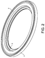
- the brush seal shown is circular around a central axis 23. It comprises first a lower cage 1 (according to the representation chosen here for the drawings). It further comprises a composite structure, composed of a ply of bristles 3 and a core 24. The latter is here hollow section and composed of a metal coil spring 5, wound in a loop around the joint and a Also open metal casing 4 C, which surrounds and protects the spring 5.
- a metal coil spring 5 wound in a loop around the joint
- a Also open metal casing 4 C which surrounds and protects the spring 5.
- Such seals are known and sold in particular under the trademark HELICOFLEX ® .
- the invention incorporates them in some of his favorite embodiments; other embodiments of the soul, comprising for example the envelope 4 alone, which gives greater flexibility, are possible.
- the layer of bristles 3 has an enveloping part 20, wound around the core 24, and parallel strands 21 and 22, directed radially inwards and responsible for sealing.
- the largest diameter of the winding 20 is called “smooth diameter" and extends, when the joint is assembled, a small distance from a face, internal to the housing, a cylindrical portion 6 which constitutes a first part of the cage 1.
- the housing is closed by an upper wedge 2 and which is crimped in the cage 1.
- the cylindrical portion 6 has for this a recess at its upper end, around which it remains in the form of a lip 7 finer.
- the wedge 2 is in contact centered with the cylindrical portion 6 of the cage 1 by a peripheral interface 6b of contact between its face of larger diameter and the inner face of the lip 7, as well as by an abutment interface 15 extension radial, advantageously perfectly flat, between its lower face and a flat face constituting the bottom of the recess of the cylindrical portion 6.
- the adjustment is accurate enough to establish a seal of the housing, thanks in particular to the flatness of the faces belonging to the abutment interface 15, and especially since the cage 1 and the wedge 2 are generally made of metal, and therefore rigid.
- the inner faces of the casing are facing each other of the cage 1 and the wedge 2 are formed concave, in tubs 9 and 10, respectively, so as to retain the composite structure.
- the winding 20 has a diameter greater than the distance between the bottoms 16 and 17 of the buckets 9 and 10.
- the buckets 9 and 10 are symmetrical and have radii of curvature at least equal, and here greater, than the radius of 20.
- the centers of curvature, as well as the bottoms 16 and 17 of the buckets 9 and 10 are aligned with the center of the winding 20 and the core 24 for each of the sections of the joint, and are of preferably at the same distance from the central axis 23.
- the composite structure is maintained at a known and repetitive position for each section and each seal is constructed in the same way, the winding 20 and the core 24 being maintained in place, being slightly compressed in the bottoms 16 and 17 of the tubs 9 and 10. They deform by flattening slightly, partially occupying the tubs 9 and 10 and widening, especially to the cylindrical portion 6.
- the radial clearance 18 between the winding 20 and the cylindrical portion 6, allows deformation without excessive stress of the composite structure inside the housing.
- a game also exists opposite the housing, on the side of the strands 21 and 22. This compression is made possible in good conditions by the flexibility and elasticity of the core 24 described here.
- the closure of the housing is done by crimping, the lip 7 of the cage 1 being folded thanks to a tool on the shim 2 by covering the edge of its outer face to the housing, opposite the bucket 10.
- the wedge 2 is shaped with two angular portions 8a and 8b, the last of which protrudes outwards in the direction of the central axis (23) of the seal.
- the cage 1 comprises a non-opening hole 19 at its outer face, which is intended to accommodate a pin 27 of greater length than the depth of this hole and which will therefore projecting. It will constitute a rotational stop system of the brush seal in its housing.
- the cage 1 and the shim 2 each contain a lip, respectively 11 and 12, protruding to the inner diameters, and whose role is to maintain the strands 21 and 22 in place by enclosing them.
- the distance between the lips 11 and 12 is defined by the abutment at the interface 15, as well as the density of the bristles in this active area.
- the lips 11 and 12 have roundings 13 and 14 at their edge adjacent to the bristles to avoid the risk of shearing them if they are bent in use.
- the outer diameter 25 of the cage 1 is an area where the sealing with the future housing of the seal will have to be ensured. It can therefore be machined with sufficient precision to allow to be fretted in this housing.
- the housing may be equipped with sealing means on its external faces.
- the figure 1 illustrates that the embodiment proposed here comprises knives 28, which are triangular section lips tapered towards the free end, standing on the outer face, flat, cage 1.
- the knives 28 are circular, concentric and support on a face opposite, also plane, 29 of the support part 30 of the seal when it is mounted.
- the outer diameter 25 of the cage 1 may comprise a flexible lip 31 projecting radially outwards and resting on a reamed face 32 of the part 30.
Landscapes
- Engineering & Computer Science (AREA)
- General Engineering & Computer Science (AREA)
- Mechanical Engineering (AREA)
- Sealing Devices (AREA)
- Turbine Rotor Nozzle Sealing (AREA)
- Gasket Seals (AREA)
Priority Applications (1)
| Application Number | Priority Date | Filing Date | Title |
|---|---|---|---|
| PL13759514T PL2893227T3 (pl) | 2012-09-10 | 2013-09-09 | Okrągła uszczelka szczotkowa |
Applications Claiming Priority (2)
| Application Number | Priority Date | Filing Date | Title |
|---|---|---|---|
| FR1258474A FR2995379B1 (fr) | 2012-09-10 | 2012-09-10 | Joint circulaire d'etancheite a brosse |
| PCT/EP2013/068547 WO2014037547A2 (fr) | 2012-09-10 | 2013-09-09 | Joint circulaire d'etancheite a brosse |
Publications (2)
| Publication Number | Publication Date |
|---|---|
| EP2893227A2 EP2893227A2 (fr) | 2015-07-15 |
| EP2893227B1 true EP2893227B1 (fr) | 2016-10-05 |
Family
ID=47178142
Family Applications (1)
| Application Number | Title | Priority Date | Filing Date |
|---|---|---|---|
| EP13759514.6A Active EP2893227B1 (fr) | 2012-09-10 | 2013-09-09 | Joint circulaire d'etancheite a brosse |
Country Status (11)
| Country | Link |
|---|---|
| US (1) | US9157531B2 (pl) |
| EP (1) | EP2893227B1 (pl) |
| JP (1) | JP6235019B2 (pl) |
| CN (1) | CN104603508B (pl) |
| BR (1) | BR112015005207B1 (pl) |
| CA (1) | CA2884556C (pl) |
| ES (1) | ES2610222T3 (pl) |
| FR (1) | FR2995379B1 (pl) |
| PL (1) | PL2893227T3 (pl) |
| RU (1) | RU2623339C2 (pl) |
| WO (1) | WO2014037547A2 (pl) |
Families Citing this family (6)
| Publication number | Priority date | Publication date | Assignee | Title |
|---|---|---|---|---|
| FR3011585B1 (fr) * | 2013-10-09 | 2018-02-23 | Safran Aircraft Engines | Assemblage pour turbomachine d'aeronef comprenant une bague frettee de maintien axial d'un joint a brosse |
| FR3027370B1 (fr) | 2014-10-15 | 2016-12-23 | Commissariat Energie Atomique | Assemblage de mise en compression de siege de vanne a boule |
| JP1558440S (pl) * | 2015-12-24 | 2016-09-12 | ||
| FR3055821B1 (fr) * | 2016-09-14 | 2019-11-08 | Valeo Systemes Thermiques | Article serti a coins sertis |
| FR3079903B1 (fr) | 2018-04-04 | 2022-12-23 | Commissariat Energie Atomique | Assemblage d'etancheite metallique pour l'etancheite entre un arbre tournant et un bati fixe |
| FR3090063B1 (fr) | 2018-12-14 | 2021-03-19 | Commissariat Energie Atomique | Joint d’étanchéité métallique comportant une couche externe d’étanchéité texturée |
Family Cites Families (13)
| Publication number | Priority date | Publication date | Assignee | Title |
|---|---|---|---|---|
| FR2151186A5 (pl) | 1971-08-24 | 1973-04-13 | Commissariat Energie Atomique | |
| DE3802653C2 (de) * | 1988-01-29 | 2000-06-29 | Mtu Muenchen Gmbh | Bürstendichtung |
| FR2692019B1 (fr) * | 1992-06-05 | 1994-07-22 | Commissariat Energie Atomique | Joint flexible a jaquette. |
| DE19529655C2 (de) * | 1995-08-11 | 1999-04-22 | Mtu Muenchen Gmbh | Bürstendichtung für Turbomaschinen |
| DE19937932C2 (de) | 1999-08-11 | 2003-07-17 | Mtu Aero Engines Gmbh | Bürstendichtring |
| DE19962316C2 (de) * | 1999-12-23 | 2002-07-18 | Mtu Aero Engines Gmbh | Bürstendichtung |
| US20100327535A1 (en) * | 2004-03-16 | 2010-12-30 | General Electric Company | Fiber seal for ceramic matrix composite components |
| US20080284107A1 (en) * | 2004-05-04 | 2008-11-20 | Flaherty Andrew L | Ceramic Brush Seals |
| EP1775502A1 (de) * | 2005-10-17 | 2007-04-18 | Siemens Aktiengesellschaft | Verfahren zum Befestigen einer Bürstendichtung |
| FR2918144B1 (fr) * | 2007-06-29 | 2009-11-06 | Snecma Sa | Joint a brosse dynamique. |
| DE102008006486A1 (de) * | 2008-01-29 | 2009-07-30 | Mtu Aero Engines Gmbh | Bürstendichtung und Verfahren zur Montage einer Bürstendichtung |
| DE102008055736A1 (de) * | 2008-11-04 | 2010-05-12 | Siemens Aktiengesellschaft | Bürstenringdichtung für eine Turbomaschine und Turbomaschine mit einer Bürstenringdichtungsanordnung |
| DE102008060371A1 (de) | 2008-12-03 | 2010-06-10 | Mtu Aero Engines Gmbh | Bürstendichtung |
-
2012
- 2012-09-10 FR FR1258474A patent/FR2995379B1/fr not_active Expired - Fee Related
-
2013
- 2013-09-09 BR BR112015005207-0A patent/BR112015005207B1/pt not_active IP Right Cessation
- 2013-09-09 ES ES13759514.6T patent/ES2610222T3/es active Active
- 2013-09-09 EP EP13759514.6A patent/EP2893227B1/fr active Active
- 2013-09-09 RU RU2015113270A patent/RU2623339C2/ru active
- 2013-09-09 JP JP2015530431A patent/JP6235019B2/ja active Active
- 2013-09-09 CN CN201380046887.1A patent/CN104603508B/zh active Active
- 2013-09-09 CA CA2884556A patent/CA2884556C/fr active Active
- 2013-09-09 US US14/423,902 patent/US9157531B2/en active Active
- 2013-09-09 PL PL13759514T patent/PL2893227T3/pl unknown
- 2013-09-09 WO PCT/EP2013/068547 patent/WO2014037547A2/fr not_active Ceased
Also Published As
| Publication number | Publication date |
|---|---|
| JP2015529315A (ja) | 2015-10-05 |
| RU2623339C2 (ru) | 2017-06-23 |
| CN104603508B (zh) | 2016-10-12 |
| ES2610222T3 (es) | 2017-04-26 |
| CA2884556C (fr) | 2019-11-26 |
| US20150226331A1 (en) | 2015-08-13 |
| CN104603508A (zh) | 2015-05-06 |
| BR112015005207B1 (pt) | 2020-09-08 |
| JP6235019B2 (ja) | 2017-11-22 |
| CA2884556A1 (fr) | 2014-03-13 |
| BR112015005207A2 (pt) | 2017-07-04 |
| FR2995379A1 (fr) | 2014-03-14 |
| EP2893227A2 (fr) | 2015-07-15 |
| WO2014037547A3 (fr) | 2014-05-08 |
| FR2995379B1 (fr) | 2014-09-05 |
| US9157531B2 (en) | 2015-10-13 |
| RU2015113270A (ru) | 2016-11-10 |
| WO2014037547A2 (fr) | 2014-03-13 |
| PL2893227T3 (pl) | 2017-06-30 |
Similar Documents
| Publication | Publication Date | Title |
|---|---|---|
| CA2884556C (fr) | Joint circulaire d'etancheite a brosse | |
| EP1911985B1 (fr) | Assemblage d'un dispositif rotulant sur une chape de renvoi d'angle, système de commande d'un redresseur à calage variable le comportant, et moteur d'aéronef en étant muni | |
| EP1564455B1 (fr) | Dispositif d'étanchéité pour turbine haute-pression de turbomachine | |
| CA2644335C (fr) | Etage de turbine ou de compresseur, en particulier de turbomachine | |
| EP2424047B1 (fr) | Contact électrique femelle, ensemble connecteur et procédé de réalisation | |
| FR2806959A1 (fr) | Procede de fabrication d'un reservoir en matiere thermoplastique soufflee incorporant un insert | |
| FR2963383A1 (fr) | Aube de turbomachine, rotor, turbine basse pression et turbomachine equipes d'une telle aube | |
| FR2961554A1 (fr) | Secteur angulaire de redresseur pour compresseur de turbomachine, redresseur de turbomachine et turbomachine comprenant un tel secteur | |
| EP3974686A1 (fr) | Système d'étanchéité métallique pour vanne papillon à triple excentration | |
| FR3108946A1 (fr) | Dispositif de fixation de deux arbres coaxiaux d’une turbomachine d’aeronef | |
| EP1855011A1 (fr) | Ensemble pour compresseur de moteur d'aéronef comprenant des aubes à attache marteau à pied incline | |
| EP1760259B1 (fr) | Dispositif d'immobilisation d'un anneau de rétention axiale d'une aube | |
| EP1090247A1 (fr) | Embout de connexion rapide ayant une piece monobloc comprenant un anneau de verrouillage et une bague additionnelle | |
| FR2892491A1 (fr) | Dispositif de raccordement a corps soude | |
| EP0576316A1 (fr) | Joint flexible à jaquette | |
| WO2018002480A1 (fr) | Ensemble de fixation d'un distributeur a un element de structure d'une turbomachine | |
| WO2023031453A1 (fr) | Armature pour réservoir de véhicule automobile. | |
| FR2877994A1 (fr) | Support de palier, et moteur d'aeronef equipe d'un tel support de palier. | |
| EP3844405B1 (fr) | Dispositif de connexion d'elements tubulaires | |
| FR3164738A1 (fr) | Secteur d’étanchéité pour turbomachine | |
| EP3714190B1 (fr) | Dispositif anti-retour de fluide monobloc dans un aeronef et procede de fabrication d'un tel dispositif | |
| BE1005640A6 (fr) | Vanne a papillon. | |
| FR2748542A1 (fr) | Dispositif pour l'accouplement etanche de deux tubes lisses | |
| FR3087484A1 (fr) | Aube de turbomachine | |
| FR2764036A1 (fr) | Thermostat a boitier en materiau synthetique assemble avec joint en l |
Legal Events
| Date | Code | Title | Description |
|---|---|---|---|
| PUAI | Public reference made under article 153(3) epc to a published international application that has entered the european phase |
Free format text: ORIGINAL CODE: 0009012 |
|
| 17P | Request for examination filed |
Effective date: 20150311 |
|
| AK | Designated contracting states |
Kind code of ref document: A2 Designated state(s): AL AT BE BG CH CY CZ DE DK EE ES FI FR GB GR HR HU IE IS IT LI LT LU LV MC MK MT NL NO PL PT RO RS SE SI SK SM TR |
|
| AX | Request for extension of the european patent |
Extension state: BA ME |
|
| RIN1 | Information on inventor provided before grant (corrected) |
Inventor name: GUIMET, LAURENT Inventor name: MENGELLE, CHRISTOPHE Inventor name: REYNAUD, PHILIPPE Inventor name: CONSTANT, OLIVIER Inventor name: LEFRANCOIS, MICHEL Inventor name: SAUVINET, FREDERIC |
|
| DAX | Request for extension of the european patent (deleted) | ||
| GRAP | Despatch of communication of intention to grant a patent |
Free format text: ORIGINAL CODE: EPIDOSNIGR1 |
|
| RIC1 | Information provided on ipc code assigned before grant |
Ipc: F16J 15/32 20060101AFI20160311BHEP |
|
| INTG | Intention to grant announced |
Effective date: 20160413 |
|
| GRAS | Grant fee paid |
Free format text: ORIGINAL CODE: EPIDOSNIGR3 |
|
| GRAA | (expected) grant |
Free format text: ORIGINAL CODE: 0009210 |
|
| AK | Designated contracting states |
Kind code of ref document: B1 Designated state(s): AL AT BE BG CH CY CZ DE DK EE ES FI FR GB GR HR HU IE IS IT LI LT LU LV MC MK MT NL NO PL PT RO RS SE SI SK SM TR |
|
| REG | Reference to a national code |
Ref country code: GB Ref legal event code: FG4D Free format text: NOT ENGLISH |
|
| REG | Reference to a national code |
Ref country code: CH Ref legal event code: NV Representative=s name: BOVARD AG, CH Ref country code: CH Ref legal event code: EP |
|
| REG | Reference to a national code |
Ref country code: AT Ref legal event code: REF Ref document number: 834960 Country of ref document: AT Kind code of ref document: T Effective date: 20161015 |
|
| REG | Reference to a national code |
Ref country code: IE Ref legal event code: FG4D Free format text: LANGUAGE OF EP DOCUMENT: FRENCH |
|
| REG | Reference to a national code |
Ref country code: DE Ref legal event code: R096 Ref document number: 602013012488 Country of ref document: DE |
|
| REG | Reference to a national code |
Ref country code: NL Ref legal event code: FP |
|
| REG | Reference to a national code |
Ref country code: SE Ref legal event code: TRGR |
|
| REG | Reference to a national code |
Ref country code: LT Ref legal event code: MG4D |
|
| PG25 | Lapsed in a contracting state [announced via postgrant information from national office to epo] |
Ref country code: LV Free format text: LAPSE BECAUSE OF FAILURE TO SUBMIT A TRANSLATION OF THE DESCRIPTION OR TO PAY THE FEE WITHIN THE PRESCRIBED TIME-LIMIT Effective date: 20161005 |
|
| REG | Reference to a national code |
Ref country code: ES Ref legal event code: FG2A Ref document number: 2610222 Country of ref document: ES Kind code of ref document: T3 Effective date: 20170426 |
|
| PG25 | Lapsed in a contracting state [announced via postgrant information from national office to epo] |
Ref country code: NO Free format text: LAPSE BECAUSE OF FAILURE TO SUBMIT A TRANSLATION OF THE DESCRIPTION OR TO PAY THE FEE WITHIN THE PRESCRIBED TIME-LIMIT Effective date: 20170105 Ref country code: GR Free format text: LAPSE BECAUSE OF FAILURE TO SUBMIT A TRANSLATION OF THE DESCRIPTION OR TO PAY THE FEE WITHIN THE PRESCRIBED TIME-LIMIT Effective date: 20170106 Ref country code: LT Free format text: LAPSE BECAUSE OF FAILURE TO SUBMIT A TRANSLATION OF THE DESCRIPTION OR TO PAY THE FEE WITHIN THE PRESCRIBED TIME-LIMIT Effective date: 20161005 |
|
| PG25 | Lapsed in a contracting state [announced via postgrant information from national office to epo] |
Ref country code: PT Free format text: LAPSE BECAUSE OF FAILURE TO SUBMIT A TRANSLATION OF THE DESCRIPTION OR TO PAY THE FEE WITHIN THE PRESCRIBED TIME-LIMIT Effective date: 20170206 Ref country code: RS Free format text: LAPSE BECAUSE OF FAILURE TO SUBMIT A TRANSLATION OF THE DESCRIPTION OR TO PAY THE FEE WITHIN THE PRESCRIBED TIME-LIMIT Effective date: 20161005 Ref country code: FI Free format text: LAPSE BECAUSE OF FAILURE TO SUBMIT A TRANSLATION OF THE DESCRIPTION OR TO PAY THE FEE WITHIN THE PRESCRIBED TIME-LIMIT Effective date: 20161005 Ref country code: IS Free format text: LAPSE BECAUSE OF FAILURE TO SUBMIT A TRANSLATION OF THE DESCRIPTION OR TO PAY THE FEE WITHIN THE PRESCRIBED TIME-LIMIT Effective date: 20170205 Ref country code: HR Free format text: LAPSE BECAUSE OF FAILURE TO SUBMIT A TRANSLATION OF THE DESCRIPTION OR TO PAY THE FEE WITHIN THE PRESCRIBED TIME-LIMIT Effective date: 20161005 |
|
| REG | Reference to a national code |
Ref country code: DE Ref legal event code: R097 Ref document number: 602013012488 Country of ref document: DE |
|
| PG25 | Lapsed in a contracting state [announced via postgrant information from national office to epo] |
Ref country code: DK Free format text: LAPSE BECAUSE OF FAILURE TO SUBMIT A TRANSLATION OF THE DESCRIPTION OR TO PAY THE FEE WITHIN THE PRESCRIBED TIME-LIMIT Effective date: 20161005 Ref country code: RO Free format text: LAPSE BECAUSE OF FAILURE TO SUBMIT A TRANSLATION OF THE DESCRIPTION OR TO PAY THE FEE WITHIN THE PRESCRIBED TIME-LIMIT Effective date: 20161005 Ref country code: EE Free format text: LAPSE BECAUSE OF FAILURE TO SUBMIT A TRANSLATION OF THE DESCRIPTION OR TO PAY THE FEE WITHIN THE PRESCRIBED TIME-LIMIT Effective date: 20161005 Ref country code: SK Free format text: LAPSE BECAUSE OF FAILURE TO SUBMIT A TRANSLATION OF THE DESCRIPTION OR TO PAY THE FEE WITHIN THE PRESCRIBED TIME-LIMIT Effective date: 20161005 |
|
| PLBE | No opposition filed within time limit |
Free format text: ORIGINAL CODE: 0009261 |
|
| STAA | Information on the status of an ep patent application or granted ep patent |
Free format text: STATUS: NO OPPOSITION FILED WITHIN TIME LIMIT |
|
| PG25 | Lapsed in a contracting state [announced via postgrant information from national office to epo] |
Ref country code: SM Free format text: LAPSE BECAUSE OF FAILURE TO SUBMIT A TRANSLATION OF THE DESCRIPTION OR TO PAY THE FEE WITHIN THE PRESCRIBED TIME-LIMIT Effective date: 20161005 Ref country code: BG Free format text: LAPSE BECAUSE OF FAILURE TO SUBMIT A TRANSLATION OF THE DESCRIPTION OR TO PAY THE FEE WITHIN THE PRESCRIBED TIME-LIMIT Effective date: 20170105 |
|
| 26N | No opposition filed |
Effective date: 20170706 |
|
| REG | Reference to a national code |
Ref country code: FR Ref legal event code: PLFP Year of fee payment: 5 |
|
| PG25 | Lapsed in a contracting state [announced via postgrant information from national office to epo] |
Ref country code: SI Free format text: LAPSE BECAUSE OF FAILURE TO SUBMIT A TRANSLATION OF THE DESCRIPTION OR TO PAY THE FEE WITHIN THE PRESCRIBED TIME-LIMIT Effective date: 20161005 |
|
| PG25 | Lapsed in a contracting state [announced via postgrant information from national office to epo] |
Ref country code: MC Free format text: LAPSE BECAUSE OF FAILURE TO SUBMIT A TRANSLATION OF THE DESCRIPTION OR TO PAY THE FEE WITHIN THE PRESCRIBED TIME-LIMIT Effective date: 20161005 |
|
| REG | Reference to a national code |
Ref country code: IE Ref legal event code: MM4A |
|
| PG25 | Lapsed in a contracting state [announced via postgrant information from national office to epo] |
Ref country code: LU Free format text: LAPSE BECAUSE OF NON-PAYMENT OF DUE FEES Effective date: 20170909 |
|
| PG25 | Lapsed in a contracting state [announced via postgrant information from national office to epo] |
Ref country code: IE Free format text: LAPSE BECAUSE OF NON-PAYMENT OF DUE FEES Effective date: 20170909 |
|
| PG25 | Lapsed in a contracting state [announced via postgrant information from national office to epo] |
Ref country code: MT Free format text: LAPSE BECAUSE OF FAILURE TO SUBMIT A TRANSLATION OF THE DESCRIPTION OR TO PAY THE FEE WITHIN THE PRESCRIBED TIME-LIMIT Effective date: 20161005 |
|
| REG | Reference to a national code |
Ref country code: FR Ref legal event code: PLFP Year of fee payment: 6 |
|
| REG | Reference to a national code |
Ref country code: AT Ref legal event code: UEP Ref document number: 834960 Country of ref document: AT Kind code of ref document: T Effective date: 20161005 |
|
| PG25 | Lapsed in a contracting state [announced via postgrant information from national office to epo] |
Ref country code: HU Free format text: LAPSE BECAUSE OF FAILURE TO SUBMIT A TRANSLATION OF THE DESCRIPTION OR TO PAY THE FEE WITHIN THE PRESCRIBED TIME-LIMIT; INVALID AB INITIO Effective date: 20130909 |
|
| PG25 | Lapsed in a contracting state [announced via postgrant information from national office to epo] |
Ref country code: CY Free format text: LAPSE BECAUSE OF FAILURE TO SUBMIT A TRANSLATION OF THE DESCRIPTION OR TO PAY THE FEE WITHIN THE PRESCRIBED TIME-LIMIT Effective date: 20161005 |
|
| PG25 | Lapsed in a contracting state [announced via postgrant information from national office to epo] |
Ref country code: MK Free format text: LAPSE BECAUSE OF FAILURE TO SUBMIT A TRANSLATION OF THE DESCRIPTION OR TO PAY THE FEE WITHIN THE PRESCRIBED TIME-LIMIT Effective date: 20161005 |
|
| PG25 | Lapsed in a contracting state [announced via postgrant information from national office to epo] |
Ref country code: TR Free format text: LAPSE BECAUSE OF FAILURE TO SUBMIT A TRANSLATION OF THE DESCRIPTION OR TO PAY THE FEE WITHIN THE PRESCRIBED TIME-LIMIT Effective date: 20161005 |
|
| PG25 | Lapsed in a contracting state [announced via postgrant information from national office to epo] |
Ref country code: AL Free format text: LAPSE BECAUSE OF FAILURE TO SUBMIT A TRANSLATION OF THE DESCRIPTION OR TO PAY THE FEE WITHIN THE PRESCRIBED TIME-LIMIT Effective date: 20161005 |
|
| PGFP | Annual fee paid to national office [announced via postgrant information from national office to epo] |
Ref country code: SE Payment date: 20220922 Year of fee payment: 10 Ref country code: NL Payment date: 20220922 Year of fee payment: 10 Ref country code: AT Payment date: 20220919 Year of fee payment: 10 |
|
| PGFP | Annual fee paid to national office [announced via postgrant information from national office to epo] |
Ref country code: PL Payment date: 20220902 Year of fee payment: 10 |
|
| PGFP | Annual fee paid to national office [announced via postgrant information from national office to epo] |
Ref country code: CH Payment date: 20220928 Year of fee payment: 10 |
|
| REG | Reference to a national code |
Ref country code: CH Ref legal event code: PL Ref country code: SE Ref legal event code: EUG |
|
| REG | Reference to a national code |
Ref country code: NL Ref legal event code: MM Effective date: 20231001 |
|
| REG | Reference to a national code |
Ref country code: AT Ref legal event code: MM01 Ref document number: 834960 Country of ref document: AT Kind code of ref document: T Effective date: 20230909 |
|
| PG25 | Lapsed in a contracting state [announced via postgrant information from national office to epo] |
Ref country code: NL Free format text: LAPSE BECAUSE OF NON-PAYMENT OF DUE FEES Effective date: 20231001 |
|
| PG25 | Lapsed in a contracting state [announced via postgrant information from national office to epo] |
Ref country code: NL Free format text: LAPSE BECAUSE OF NON-PAYMENT OF DUE FEES Effective date: 20231001 |
|
| PG25 | Lapsed in a contracting state [announced via postgrant information from national office to epo] |
Ref country code: CH Free format text: LAPSE BECAUSE OF NON-PAYMENT OF DUE FEES Effective date: 20230930 |
|
| PG25 | Lapsed in a contracting state [announced via postgrant information from national office to epo] |
Ref country code: AT Free format text: LAPSE BECAUSE OF NON-PAYMENT OF DUE FEES Effective date: 20230909 |
|
| PG25 | Lapsed in a contracting state [announced via postgrant information from national office to epo] |
Ref country code: CH Free format text: LAPSE BECAUSE OF NON-PAYMENT OF DUE FEES Effective date: 20230930 Ref country code: AT Free format text: LAPSE BECAUSE OF NON-PAYMENT OF DUE FEES Effective date: 20230909 |
|
| PG25 | Lapsed in a contracting state [announced via postgrant information from national office to epo] |
Ref country code: SE Free format text: LAPSE BECAUSE OF NON-PAYMENT OF DUE FEES Effective date: 20230910 |
|
| PG25 | Lapsed in a contracting state [announced via postgrant information from national office to epo] |
Ref country code: PL Free format text: LAPSE BECAUSE OF NON-PAYMENT OF DUE FEES Effective date: 20230909 |
|
| PG25 | Lapsed in a contracting state [announced via postgrant information from national office to epo] |
Ref country code: PL Free format text: LAPSE BECAUSE OF NON-PAYMENT OF DUE FEES Effective date: 20230909 |
|
| PGFP | Annual fee paid to national office [announced via postgrant information from national office to epo] |
Ref country code: DE Payment date: 20250919 Year of fee payment: 13 |
|
| PGFP | Annual fee paid to national office [announced via postgrant information from national office to epo] |
Ref country code: BE Payment date: 20250919 Year of fee payment: 13 Ref country code: GB Payment date: 20250923 Year of fee payment: 13 |
|
| PGFP | Annual fee paid to national office [announced via postgrant information from national office to epo] |
Ref country code: FR Payment date: 20250924 Year of fee payment: 13 |
|
| PGFP | Annual fee paid to national office [announced via postgrant information from national office to epo] |
Ref country code: CZ Payment date: 20250827 Year of fee payment: 13 |
|
| PGFP | Annual fee paid to national office [announced via postgrant information from national office to epo] |
Ref country code: IT Payment date: 20250930 Year of fee payment: 13 |
|
| PGFP | Annual fee paid to national office [announced via postgrant information from national office to epo] |
Ref country code: ES Payment date: 20251020 Year of fee payment: 13 |