EP2892815B1 - Pourer with retractable spout - Google Patents
Pourer with retractable spout Download PDFInfo
- Publication number
- EP2892815B1 EP2892815B1 EP13765493.5A EP13765493A EP2892815B1 EP 2892815 B1 EP2892815 B1 EP 2892815B1 EP 13765493 A EP13765493 A EP 13765493A EP 2892815 B1 EP2892815 B1 EP 2892815B1
- Authority
- EP
- European Patent Office
- Prior art keywords
- pourer
- tubular body
- pouring
- pouring spout
- container
- Prior art date
- Legal status (The legal status is an assumption and is not a legal conclusion. Google has not performed a legal analysis and makes no representation as to the accuracy of the status listed.)
- Active
Links
Images


Classifications
-
- B—PERFORMING OPERATIONS; TRANSPORTING
- B65—CONVEYING; PACKING; STORING; HANDLING THIN OR FILAMENTARY MATERIAL
- B65D—CONTAINERS FOR STORAGE OR TRANSPORT OF ARTICLES OR MATERIALS, e.g. BAGS, BARRELS, BOTTLES, BOXES, CANS, CARTONS, CRATES, DRUMS, JARS, TANKS, HOPPERS, FORWARDING CONTAINERS; ACCESSORIES, CLOSURES, OR FITTINGS THEREFOR; PACKAGING ELEMENTS; PACKAGES
- B65D47/00—Closures with filling and discharging, or with discharging, devices
- B65D47/04—Closures with discharging devices other than pumps
- B65D47/06—Closures with discharging devices other than pumps with pouring spouts or tubes; with discharge nozzles or passages
- B65D47/061—Closures with discharging devices other than pumps with pouring spouts or tubes; with discharge nozzles or passages with telescopic, retractable or reversible spouts, tubes or nozzles
-
- B—PERFORMING OPERATIONS; TRANSPORTING
- B65—CONVEYING; PACKING; STORING; HANDLING THIN OR FILAMENTARY MATERIAL
- B65D—CONTAINERS FOR STORAGE OR TRANSPORT OF ARTICLES OR MATERIALS, e.g. BAGS, BARRELS, BOTTLES, BOXES, CANS, CARTONS, CRATES, DRUMS, JARS, TANKS, HOPPERS, FORWARDING CONTAINERS; ACCESSORIES, CLOSURES, OR FITTINGS THEREFOR; PACKAGING ELEMENTS; PACKAGES
- B65D25/00—Details of other kinds or types of rigid or semi-rigid containers
- B65D25/38—Devices for discharging contents
- B65D25/40—Nozzles or spouts
- B65D25/48—Separable nozzles or spouts
Definitions
- the present invention concerns a pourer with a retractable spout.
- Pourers with retractable spouts are known in the art, for instance, from EP 2 371 730 , EP 1 831 082 , FR 2 799 739 , US 6,026,994 .
- EP 2371739 discloses a pouring cap comprising an upper closing member and a lower element able to be attached to a bottle neck.
- the cap comprises a tubular ring downwardly projecting from the upper wall of the cap and having an external protuberance.
- the lower element is equipped with a retractable spout and with means for attaching the upper end of the spout to the protuberance of the tubular ring of the cap.
- the pouring spout has an annular lip.
- the lower element also comprises a duct for the entry of air which allows communication between the inside and the outside of the container.
- EP 1831082 discloses a pourer that comprises an insert designed to be fixed to a bottle and defining a liquid passage, a pouring spout configured to project from the insert and a closing cap.
- the insert also comprises a passage for air.
- the cap comprises wings which are able to engage with the pouring spout for extraction thereof upon cap removal.
- FR 2799739 discloses a pourer that comprises a body having means for fixation to a container neck; a center tube that can axially move relative to the body and connecting means for connection of the body with the center tube, as well as means for displacing the center tube relative to the body.
- the pourer has an oblique opening for the passage of air, which is formed in a common lower base of the center tube and the body.
- a pourer that comprises a sleeve designed to be fixed to a bottle neck, a pouring spout that is movable relative to the sleeve between an extended position and a retracted position and elastic members operating on the pouring spout to hold it in the extended position and able to be compressed to allow the spout to move toward the retracted position.
- the spout also comprises a conduit for the passage of air which is placed opposite to a reference cut formed on the upper end of the spout. While this pourer partially solves the above mentioned technical problem, it reduces the liquid passage channel defined by the spout, because part of it is used as an air passage channel.
- GB 142862 discloses a pourer with a retractable spout having a pin that engages a slot formed in a sleeve for guiding and maintaining the angular orientation of the spout relative to the sleeve. Nevertheless, the spout has no element for determining a pouring orientation of the pourer. Furthermore, liquid is forced to flow through the slot, the latter fulfilling both purposes of providing an opening for the passage of liquid, and acting as a guide element. Due to this dual purpose, the slot provides a reduced and inadequate opening for the passage of liquid.
- DE 8603167 discloses a pourer with a retractable spout having a lip that has such a shape as to define an orientation of the pourer.
- the spout is coupled to the pourer body via guiding and rotation-preventing members. Nevertheless, with this pourer, during pouring, the first part of liquid flowing from the container forms an uncontrolled jet that may be directed where the user does not want to pour the product.
- the subject-matter of claim 1 differs from this prior art in that an anti-slosking wall is foreseen.
- the object of the present invention is to fulfill the above need, while obviating prior art drawbacks.
- numeral 10 generally designates a pourer according to an embodiment of the present invention.
- the pourer 10 is designed to be fitted to a container 1, such as an oil bottle and to be closed by a cap 100.
- the assembly composed of the pourer 10 and the cap 100 is generally referenced 101.
- the container 1 is a bottle and comprises a neck 2 that terminates in a mouth 3 defining an orifice 4.
- the neck 3 has threads 3a designed for engagement of threads 100a of the cap 100.
- the pourer 10 is designed to be fitted to the mouth 3 of the container 1.
- the vertical axis will be defined as the longitudinal axis X-X of the pourer 10 and conventionally the bottom side will be the side of the pourer 10 designed to face the container 1, and the top side will be the one designed to face the consumer; this is actually the normal orientation of the pourer 10 when fitted to a normally oriented bottle.
- liquid flowing out of the pourer 10 will be conventionally directed from the side designed to face the container 1 to the side designed to face the consumer.
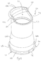
- the pourer 10 comprises a tubular body 20 and a pouring spout 40.
- the tubular body 20 extends along the longitudinal direction X-X between a lower portion 21 and an upper portion 22.
- the pourer 10 is able to be attached to the container 1 and, for this purpose, the tubular body 20 comprises attachment members 23 for attaching the tubular body 20 to the neck 2 of the container 1.
- the tubular body 20 is coupled to the neck 2 by an "in-bore" arrangement.
- other arrangements may be provided for the connection of the tubular body 20 to the neck 2.
- the attachment members 23 comprise a plurality of annular wings 24, which are longitudinally spaced over the outer surface 20a of the tubular body 20.
- the tubular body 20 also has a flange 25, extending transverse to the longitudinal direction X-X and able to abut against the upper end of the neck 2 of the container 1, when the pourer 10 is fitted to the container 1.
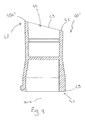
- the tubular body 20 comprises an inner sleeve 26, an outer sleeve 27 and a connecting flange 28 for connecting the inner and outer sleeves 26, 27.
- a C channel 32 is defined between the outer surface of the inner sleeve 26 and the inner surface of the outer sleeve 27.
- the attachment members 23 and the flange 25 are formed on the outer sleeve 27.
- the inner sleeve 26 delimits inside a tubular cavity 29 whose purpose is described hereinafter.
- the inner sleeve 26 extends longitudinally between a lower portion 26a and an outer portion 26b and the outer sleeve 27 extends longitudinally between a lower portion 27a and an upper portion 27b.
- the tubular body 20 comprises a wall 30 that extends on a plane substantially perpendicular to the longitudinal direction X-X to intercept the liquid flowing from the container 1 to the upper portion 22 of the tubular body 20.
- This wall 20 acts as a breakwater for the liquid that flows from the container 1 to the upper portion 22 and prevents the first part of liquid from the container to form an uncontrolled jet, upon pouring, and from flowing to areas in which the user does not want to pour the product.
- the wall 20 is placed at the lower portion 26a of the inner sleeve 26.
- the inner sleeve 26 is closed at its bottom by the wall 30.
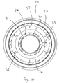
- the tubular body 20 has at least one liquid passage opening 31 formed on the side of the tubular body 20, particularly on the side of the inner sleeve 26, above the wall 30, to allow the flow of liquid to the upper portion 22 of the tubular body 20.
- the at least one liquid passage opening 31 comprises a plurality of liquid passage openings 31 in angularly spaced arrangement.
- the tubular body 20 may comprise a single sleeve.
- the lower portion of such sleeve will taper toward the axis X-X of the pourer 10 o have a smaller diameter than the interior of the neck 2 of the container 1 near the mouth 3 to allow the liquid to flow from the interior of the container through the liquid passage openings 31.
- the liquid passage openings 31 are formed in the lower portion 26a of the inner sleeve 26, immediately adjacent to the wall 30.
- the openings 31 are designed to allow fluid communication between the interior of the container 1 and the tubular cavity 29.
- the liquid that flows from the container 1 to the upper portion 22 is slowed down by the wall 30 and is forced to flow through the liquid passage openings 31 to reach the upper portion 22 of the tubular body 20.
- the tubular body 20 has a passage conduit 33 for allowing fluid communication between the inside and the outside of the container 1.
- the passage conduit 33 is associated with the tubular body 20, here to both inner and outer sleeves 26, 27 and extends longitudinally, with the longitudinal axis X'-X' parallel to the longitudinal axis X-X, between a lower opening 33a, here substantially level with the lower portion 21, particularly level with the wall 30, and an upper opening 33b, here formed in the connecting flange 28.
- the passage conduit 33 is placed between the inner sleeve 26 and the outer sleeve 27 and breaks the continuity of the C channel 32.
- this passage conduit 33 defines an air passage conduit from the outside to the inside of the container 1, to allow constant pouring of the liquid from the container 1.
- the connecting flange 28 is inclined, here at about 3°, relative to a plane perpendicular to the longitudinal axis X-X of the pourer 10, to define a lower area 28a and an upper area 28b.
- the upper opening 33b of the passage conduit 33 is placed at the lower area 28a of the flange 28.
- the passage conduit 33 is attached to the inner sleeve 26 and the outer sleeve 27, and is particularly formed of one piece with the inner and outer sleeves 26, 27.
- Figure 9 shows an alternative embodiment in which the passage conduit 33 is attached to the inner sleeve 26 and is separate from the outer sleeve 27.
- the passage conduit 33 is radially spaced from the outer sleeve 27 at a distance d.
- the distance d is longitudinally constant, although this distance might change, for construction requirements, in a range from a minimum value to a maximum value.
- the passage conduit 33 is prevented from being compressed between the walls of the two sleeves 26, 27, when the pourer 10 is fitted to the neck of a container. In certain cases, the construction tolerances of the neck of the container might cause compression on the outer sleeve 27, that would directly affect the passage conduit 33.
- the passage conduit 33 may be arranged to be attached to the outer sleeve 27, such that the passage conduit 33 may be at a distance d from the inner sleeve 26.
- the pouring spout 40 is accommodated within the tubular body 20 and is movable to reversibly slide relative to the tubular body 20, in the example of the tubular cavity 29 of the inner sleeve 26, along the longitudinal direction X-X, between a retracted position, in which the pourer 10 is designed to be closed by the cap 100 and an extracted position, in which the pourer 10 is designed to pour the liquid contained in the container 1 through the pouring spout 40.
- the pouring spout 40 extends along the longitudinal direction X-X between a lower portion 41 and an upper portion 42.
- the pouring spout 40 has a pouring rim 45, which is conformed to define a pouring orientation of the pourer 10.
- the pouring rim 45 extends angularly between two ends 45b, 45c along a circumferential portion of the pouring spout 40. Particularly, the pouring rim 45 extends between the two ends 45b, 45c to define the correct pouring position of the pourer 10.
- the pouring rim 45 projects radially to form a pouring lip.
- the pouring spout 40, and hence the pourer 10 is also effective in pouring high-viscosity liquids.
- Figure 9 shows by way of example and without limitation a pouring spout 40 with a beveled pouring rim 45', as disclosed in US 6,026,994 .
- the pouring spout 40 has an annular edge 43 at its upper portion 42, that defines a pouring orifice 44.
- a portion of the annular edge 43 projects radially, transverse to the axis X-X to form the pouring lip 45. Therefore, the pouring lip 45 extends angularly over a circumferential portion of the annular edge 43.
- the pouring lip 45 extends angularly between 120 and 180°, in this example 160°.
- the pouring lip 45 has a middle region 45a between the two ends 45b, 45c.
- the middle region 45a of the lip 45 is located opposite to the passage conduit 33 with respect to the longitudinal axis X-X of the pourer 10, advantageously aligned with a line that passes through the axis X-X and the axis X'-X' of the passage conduit 33.
- one of the liquid passage openings 31 and the middle region 45a of the pouring lip 45 have the same angular orientation.
- this liquid passage opening 31 is formed opposite to the passage conduit 33 with respect to the longitudinal axis X-X.
- the central portion of one of the liquid passage openings 31 is advantageously aligned with a line that intersects the axis X-X of the tubular body 20 and the axis X'-X' of the passage conduit 33, perpendicular to such axes X-X and X'-X'.
- the pourer 10 can have an effective pouring operation even when the user holds the container with the pouring rim 45 in a wrong position, during pouring.
- the pouring rim 45 may be angularly spaced from its optimal position, i.e. with the middle region 45a facing the area where the liquid is designed to be poured. Nevertheless, the presence of multiple liquid passage openings 31 ensures a proper pouring operation as long as the liquid that flows out of the container intercepts at least one of them.
- the tubular body 20 and the pouring spout 40 are coupled together by coupling means 46 that are able to guide the movement of the pouring spout 40 relative to the tubular body 20 between the retracted and extracted positions and prevent rotation of the pouring spout 40 relative to the tubular body 20 to hold the relative angular position of the pouring rim 45 with respect to the tubular body 20 and hence, for instance, the relative position of the pouring lip 45 with respect to the passage conduit 33.
- any angular rotation tolerance of the pouring lip 45 relative to the tubular body 20, as required in the process of mounting and assembling the pourer 10 are deemed to fall within the definition of maintenance of the relative angular position of the pouring lip 45 with respect to the tubular body 20.
- the coupling means 46 comprise at least one first guide element 47 formed inside on the tubular body 20 and at least one second guide element 48 formed outside on the pouring spout 40 and operatively coupled to the first guide element 47 to allow the pouring spout 40 to slide relative to the tubular body 20.
- the coupling means 46 are distinct from the liquid passage openings 31. This particularly allows positioning of the passage openings 31 and selection of their dimensional characteristics irrespective of any dimensional requirements of the coupling means 46, thereby optimizing liquid flow from within the container 1 to the pouring spout 40.
- the at least one first guide element 47 comprises a plurality of angularly spaced longitudinal ribs, here three ribs, formed in the tubular body 30, here on the inner surface of the inner sleeve 26, and the at least one second guide element 48 comprises a corresponding plurality of angularly spaced recesses 48, here three recesses, formed outside the pouring spout 40, i.e. on the outer surface of the pouring spout 40, each rib 47 being engaged in a corresponding recess 48 to guide the longitudinal movement of the pouring spout 40 between the retracted and extracted positions and to prevent rotation of the pouring spout 40 relative to the tubular body 20.
- the recesses 48 are formed in an annular flange 49 which is placed at the bottom end 41 of the pouring spout 40 and projects from the pouring spout 40 perpendicular to the longitudinal direction X-X.
- the pourer 10 comprises first stop means 50 for stopping the pouring spout 40 in the extracted position.
- the first stop means 50 comprise an annular rib 51 formed in the upper portion 22 of the tubular body 20, here in the upper portion 26b of the inner sleeve 26 against which the annular flange 49 is designed to abut for stopping the movement of the pouring spout 40 from the retracted position to the extracted position.
- the pouring spout 40 has a tapered part 41b whose diameter increases toward the lower portion 41 such that, when the annular flange 49 abuts against the annular rib 48, a part 41 a of the lower portion 41 of the pouring spout 40 engages the annular rib 51 by an interference fit.
- lock means may be provided, or the first stop means 50 may be configured to stop and reversibly lock the pouring spout 40 in the extracted position.
- Second stop means 52 are provided to stop the pouring spout 40 in the retracted position.
- the second stop means 52 consist of the wall 30 against which the lower portion 41 of the pouring spout 40, particularly the flange 49, abuts, during the movement from the extracted position to the retracted position.
- the pouring spout 40 may be extracted from the tubular body 20 by directly acting upon the pouring spout 40, e.g. manually, or by the action of spring members arranged between the wall 30 and the flange 49, or as shown, by providing coupling means 60 carried by the cap 100.
- the cap 100 has a sleeve 61 with coupling means 62 for engaging corresponding coupling elements 62 carried by the pouring spout 40.
- the coupling elements 62 comprise an annular lip which is designed to engage an annular rib 62 formed on the inner surface of the pouring spout 40.
- the action of removing the cap 100 from the pourer 10 causes the annular lip 62 to engage the annular rib 63.
- the longitudinal movement of the cap 100 causes a corresponding longitudinal movement of the pouring spout 40 until the annular lip 62 acts upon the annular rib 63.
- a further longitudinal movement of the cap 100 causes disengagement of the annular lip 62 from the annular rib 63 and the cap 100 may be removed from the pourer 10.
- the annular lip 62 acts upon the top of the annular rib 63 to move the pouring spout 40 back to the retracted position.
- the position of the annular lip 62 and the annular rib 63 are selected to allow the pouring spout 40 to be stopped in the retracted position before full closure of the pourer 10 by the cap 100.
- the cap 100 comprises an undercap 102 from which the sleeve 61 with the coupling elements 62 projects downwards.
- the undercap 102 has a capsule 103 having threads 100a mounted thereto, with an upper portion 103a attached to the undercap 102 and a lower portion 103b attached to the neck 2 of the container 1.
- Bridges 104 connect the lower portion 103b to the upper portion 103a and are designed to break upon first opening of the container 1.
- the capsule 103 is fitted to the container 1 by a rolling process, that is known per se and will not be further described herein.
- the continuity of the pourer components may be broken in any manner, provided that no functional alteration to the relevant component is caused thereby.
Landscapes
- Engineering & Computer Science (AREA)
- Mechanical Engineering (AREA)
- Closures For Containers (AREA)
- Cartons (AREA)
Description
- The present invention concerns a pourer with a retractable spout.
- Pourers with retractable spouts are known in the art, for instance, from
EP 2 371 730EP 1 831 082FR 2 799 739US 6,026,994 . -
EP 2371739 discloses a pouring cap comprising an upper closing member and a lower element able to be attached to a bottle neck. The cap comprises a tubular ring downwardly projecting from the upper wall of the cap and having an external protuberance. The lower element is equipped with a retractable spout and with means for attaching the upper end of the spout to the protuberance of the tubular ring of the cap. At the upper end, the pouring spout has an annular lip. The lower element also comprises a duct for the entry of air which allows communication between the inside and the outside of the container. -
EP 1831082 discloses a pourer that comprises an insert designed to be fixed to a bottle and defining a liquid passage, a pouring spout configured to project from the insert and a closing cap. The insert also comprises a passage for air. The cap comprises wings which are able to engage with the pouring spout for extraction thereof upon cap removal. -
FR 2799739 - The above mentioned technical solutions have a common drawback: they do not allow a user to easily confirm proper pouring orientation of the container with the pourer mounted thereto, whereby pouring effectiveness of pourers will depend on the random orientation of the container when a user takes hold of it. Here, the passage for air may not be in the desired position, i.e. ideally opposite to the area through which the liquid flows out of the container. Of course, user guiding systems may be provided, but this will affect pourer mounting flexibility, as well as the general cost-effectiveness of the container.
- A solution to this drawback was provided in
US 6,026,994 . This document discloses a pourer that comprises a sleeve designed to be fixed to a bottle neck, a pouring spout that is movable relative to the sleeve between an extended position and a retracted position and elastic members operating on the pouring spout to hold it in the extended position and able to be compressed to allow the spout to move toward the retracted position. The spout also comprises a conduit for the passage of air which is placed opposite to a reference cut formed on the upper end of the spout. While this pourer partially solves the above mentioned technical problem, it reduces the liquid passage channel defined by the spout, because part of it is used as an air passage channel. - Further pourers with retractable spouts are disclosed, for instance, by
GB 142862 DE 8603167U FR 1375655 US 2011/266251 ,DE 1482530 ,DE 1482576 andUS 1473925 . -
GB 142862 -
DE 8603167 discloses a pourer with a retractable spout having a lip that has such a shape as to define an orientation of the pourer. The spout is coupled to the pourer body via guiding and rotation-preventing members. Nevertheless, with this pourer, during pouring, the first part of liquid flowing from the container forms an uncontrolled jet that may be directed where the user does not want to pour the product. Thus, the subject-matter ofclaim 1 differs from this prior art in that an anti-slosking wall is foreseen. - In the light of the background art as discussed above, the need arises for a pourer that can indicate the right orientation for effective pouring to the user, while slowing down the liquid that flows from the container toward the pouring orifice of the retractable spout.
- In view of the above discussed prior art, the object of the present invention is to fulfill the above need, while obviating prior art drawbacks.
- According to the present invention, this object is fulfilled by a pourer as defined in
claim 1. - The characteristics and advantages of the present invention will appear from the following detailed description of one practical embodiment, which is illustrated without limitation in the annexed drawings, in which:
-
Figure 1 shows a side view of a cap mounted to the neck of a container, that has the pourer of the present invention fixed thereto, -
Figure 2 shows a sectional view ofFigure 1 , with the spout in a retracted position, -
Figure 3 shows a perspective view of the pourer as assembled with the container with the spout in an extracted position, -
Figure 4 shows a sectional view ofFigure 3 , -
Figure 5 shows a perspective view of the tubular body of the pourer, -
Figure 6 shows a top plan view of the tubular body ofFigure 5 , -
Figure 7 shows a sectional view of the tubular body ofFigure 5 , -
Figure 8 shows a perspective view of the tubular body of the pouring spout, -
Figure 9 shows a perspective view of an alternative embodiment of a spout for the pourer of the present invention, -
Figure 10 shows a sectional view of an alternative embodiment of a tubular body for the pourer of the present invention. - Although this is not expressly shown, the individual features described with reference to each embodiment shall be intended as auxiliary and/or interchangeable with other features, as described with reference to other embodiments.
- Referring to the annexed figures,
numeral 10 generally designates a pourer according to an embodiment of the present invention. - The
pourer 10 is designed to be fitted to acontainer 1, such as an oil bottle and to be closed by acap 100. The assembly composed of thepourer 10 and thecap 100 is generally referenced 101. - In the example of the figures, the
container 1 is a bottle and comprises aneck 2 that terminates in amouth 3 defining anorifice 4. Theneck 3 has threads 3a designed for engagement of threads 100a of thecap 100. - Thus, the
pourer 10 is designed to be fitted to themouth 3 of thecontainer 1. - While the
pourer 10 in itself may be oriented in any direction, for the purposes of the present direction the vertical axis will be defined as the longitudinal axis X-X of thepourer 10 and conventionally the bottom side will be the side of thepourer 10 designed to face thecontainer 1, and the top side will be the one designed to face the consumer; this is actually the normal orientation of thepourer 10 when fitted to a normally oriented bottle. - Likewise, the liquid flowing out of the
pourer 10 will be conventionally directed from the side designed to face thecontainer 1 to the side designed to face the consumer. - The
pourer 10 comprises atubular body 20 and apouring spout 40. - The
tubular body 20 extends along the longitudinal direction X-X between a lower portion 21 and anupper portion 22. - The
pourer 10 is able to be attached to thecontainer 1 and, for this purpose, thetubular body 20 comprisesattachment members 23 for attaching thetubular body 20 to theneck 2 of thecontainer 1. In this example, thetubular body 20 is coupled to theneck 2 by an "in-bore" arrangement. Alternatively, other arrangements may be provided for the connection of thetubular body 20 to theneck 2. - According to an embodiment, the
attachment members 23 comprise a plurality ofannular wings 24, which are longitudinally spaced over the outer surface 20a of thetubular body 20. - The
tubular body 20 also has aflange 25, extending transverse to the longitudinal direction X-X and able to abut against the upper end of theneck 2 of thecontainer 1, when thepourer 10 is fitted to thecontainer 1. - According to one embodiment, the
tubular body 20 comprises aninner sleeve 26, anouter sleeve 27 and a connectingflange 28 for connecting the inner andouter sleeves A C channel 32 is defined between the outer surface of theinner sleeve 26 and the inner surface of theouter sleeve 27. In this embodiment, theattachment members 23 and theflange 25 are formed on theouter sleeve 27. Theinner sleeve 26 delimits inside atubular cavity 29 whose purpose is described hereinafter. - The
inner sleeve 26 extends longitudinally between a lower portion 26a and an outer portion 26b and theouter sleeve 27 extends longitudinally between alower portion 27a and an upper portion 27b. - At the lower portion 21, the
tubular body 20 comprises awall 30 that extends on a plane substantially perpendicular to the longitudinal direction X-X to intercept the liquid flowing from thecontainer 1 to theupper portion 22 of thetubular body 20. Thiswall 20 acts as a breakwater for the liquid that flows from thecontainer 1 to theupper portion 22 and prevents the first part of liquid from the container to form an uncontrolled jet, upon pouring, and from flowing to areas in which the user does not want to pour the product. - According to one embodiment, the
wall 20 is placed at the lower portion 26a of theinner sleeve 26. Particularly, theinner sleeve 26 is closed at its bottom by thewall 30. - At the
lower portion 2, thetubular body 20 has at least one liquid passage opening 31 formed on the side of thetubular body 20, particularly on the side of theinner sleeve 26, above thewall 30, to allow the flow of liquid to theupper portion 22 of thetubular body 20. Advantageously, the at least oneliquid passage opening 31 comprises a plurality ofliquid passage openings 31 in angularly spaced arrangement. - Alternatively, the
tubular body 20 may comprise a single sleeve. In the case of an "in-bore" fitting of the sleeve, the lower portion of such sleeve will taper toward the axis X-X of the pourer 10 o have a smaller diameter than the interior of theneck 2 of thecontainer 1 near themouth 3 to allow the liquid to flow from the interior of the container through theliquid passage openings 31. - Reference will be made hereinafter, without limitation, to a plurality of
liquid passage openings 31. - In this example, the
liquid passage openings 31 are formed in the lower portion 26a of theinner sleeve 26, immediately adjacent to thewall 30. Theopenings 31 are designed to allow fluid communication between the interior of thecontainer 1 and thetubular cavity 29. During the pouring operation, the liquid that flows from thecontainer 1 to theupper portion 22 is slowed down by thewall 30 and is forced to flow through theliquid passage openings 31 to reach theupper portion 22 of thetubular body 20. - According to one embodiment, the
tubular body 20 has apassage conduit 33 for allowing fluid communication between the inside and the outside of thecontainer 1. According to one embodiment, thepassage conduit 33 is associated with thetubular body 20, here to both inner andouter sleeves wall 30, and an upper opening 33b, here formed in the connectingflange 28. In this example, thepassage conduit 33 is placed between theinner sleeve 26 and theouter sleeve 27 and breaks the continuity of theC channel 32. - During the pouring operation, this
passage conduit 33 defines an air passage conduit from the outside to the inside of thecontainer 1, to allow constant pouring of the liquid from thecontainer 1. In the embodiment of the figures, the connectingflange 28 is inclined, here at about 3°, relative to a plane perpendicular to the longitudinal axis X-X of thepourer 10, to define a lower area 28a and an upper area 28b. In order to allow recovery of any liquid leaking or falling from the pouringspout 40 upon pouring, the upper opening 33b of thepassage conduit 33 is placed at the lower area 28a of theflange 28. - In the embodiment of
Figures 1 to 8 , thepassage conduit 33 is attached to theinner sleeve 26 and theouter sleeve 27, and is particularly formed of one piece with the inner andouter sleeves -
Figure 9 shows an alternative embodiment in which thepassage conduit 33 is attached to theinner sleeve 26 and is separate from theouter sleeve 27. Particularly, thepassage conduit 33 is radially spaced from theouter sleeve 27 at a distance d. Here, the distance d is longitudinally constant, although this distance might change, for construction requirements, in a range from a minimum value to a maximum value. In this embodiment, thepassage conduit 33 is prevented from being compressed between the walls of the twosleeves pourer 10 is fitted to the neck of a container. In certain cases, the construction tolerances of the neck of the container might cause compression on theouter sleeve 27, that would directly affect thepassage conduit 33. - Alternatively to the configuration of
Figure 9 , thepassage conduit 33 may be arranged to be attached to theouter sleeve 27, such that thepassage conduit 33 may be at a distance d from theinner sleeve 26. - The pouring
spout 40 is accommodated within thetubular body 20 and is movable to reversibly slide relative to thetubular body 20, in the example of thetubular cavity 29 of theinner sleeve 26, along the longitudinal direction X-X, between a retracted position, in which thepourer 10 is designed to be closed by thecap 100 and an extracted position, in which thepourer 10 is designed to pour the liquid contained in thecontainer 1 through the pouringspout 40. - The pouring
spout 40 extends along the longitudinal direction X-X between alower portion 41 and anupper portion 42. - The pouring
spout 40 has a pouringrim 45, which is conformed to define a pouring orientation of thepourer 10. - In one embodiment, the pouring
rim 45 extends angularly between twoends 45b, 45c along a circumferential portion of the pouringspout 40. Particularly, the pouringrim 45 extends between the two ends 45b, 45c to deine the correct pouring position of thepourer 10. - According to one embodiment and as shown in Figures from 1 to 8, the pouring
rim 45 projects radially to form a pouring lip. Thus, the pouringspout 40, and hence thepourer 10, is also effective in pouring high-viscosity liquids. -
Figure 9 shows by way of example and without limitation a pouringspout 40 with a beveled pouring rim 45', as disclosed inUS 6,026,994 . - Reference will be made hereinafter, without limitation, to the pouring
rim 45. - In the example of the figures, the pouring
spout 40 has anannular edge 43 at itsupper portion 42, that defines a pouringorifice 44. A portion of theannular edge 43 projects radially, transverse to the axis X-X to form the pouringlip 45. Therefore, the pouringlip 45 extends angularly over a circumferential portion of theannular edge 43. Preferably, the pouringlip 45 extends angularly between 120 and 180°, in this example 160°. - The pouring
lip 45 has a middle region 45a between the two ends 45b, 45c. According to one embodiment, the middle region 45a of thelip 45 is located opposite to thepassage conduit 33 with respect to the longitudinal axis X-X of thepourer 10, advantageously aligned with a line that passes through the axis X-X and the axis X'-X' of thepassage conduit 33. Thus, during pouring, if the pouringspout 40 is used with the pouring rim substantially below the rest of the pouringedge 43, thepassage conduit 33 effectively operates to allow air passage as the lower opening 33a is not obstructed by the liquid that flows out of thecontainer 1. - According to one embodiment, one of the
liquid passage openings 31 and the middle region 45a of the pouringlip 45 have the same angular orientation. - Therefore, this
liquid passage opening 31 is formed opposite to thepassage conduit 33 with respect to the longitudinal axis X-X. Advantageously, the central portion of one of theliquid passage openings 31 is advantageously aligned with a line that intersects the axis X-X of thetubular body 20 and the axis X'-X' of thepassage conduit 33, perpendicular to such axes X-X and X'-X'. - Depending on the number and angular extension of the remaining
liquid passage openings 31, thepourer 10 can have an effective pouring operation even when the user holds the container with the pouringrim 45 in a wrong position, during pouring. Particularly, the pouringrim 45 may be angularly spaced from its optimal position, i.e. with the middle region 45a facing the area where the liquid is designed to be poured. Nevertheless, the presence of multipleliquid passage openings 31 ensures a proper pouring operation as long as the liquid that flows out of the container intercepts at least one of them. - The
tubular body 20 and the pouringspout 40 are coupled together by coupling means 46 that are able to guide the movement of the pouringspout 40 relative to thetubular body 20 between the retracted and extracted positions and prevent rotation of the pouringspout 40 relative to thetubular body 20 to hold the relative angular position of the pouringrim 45 with respect to thetubular body 20 and hence, for instance, the relative position of the pouringlip 45 with respect to thepassage conduit 33. - It shall be noted that any angular rotation tolerance of the pouring
lip 45 relative to thetubular body 20, as required in the process of mounting and assembling thepourer 10 are deemed to fall within the definition of maintenance of the relative angular position of the pouringlip 45 with respect to thetubular body 20. - According to one embodiment, the coupling means 46 comprise at least one
first guide element 47 formed inside on thetubular body 20 and at least onesecond guide element 48 formed outside on the pouringspout 40 and operatively coupled to thefirst guide element 47 to allow the pouringspout 40 to slide relative to thetubular body 20. - It shall be noted that the coupling means 46 are distinct from the
liquid passage openings 31. This particularly allows positioning of thepassage openings 31 and selection of their dimensional characteristics irrespective of any dimensional requirements of the coupling means 46, thereby optimizing liquid flow from within thecontainer 1 to the pouringspout 40. - According to one embodiment, the at least one
first guide element 47 comprises a plurality of angularly spaced longitudinal ribs, here three ribs, formed in thetubular body 30, here on the inner surface of theinner sleeve 26, and the at least onesecond guide element 48 comprises a corresponding plurality of angularly spaced recesses 48, here three recesses, formed outside the pouringspout 40, i.e. on the outer surface of the pouringspout 40, eachrib 47 being engaged in acorresponding recess 48 to guide the longitudinal movement of the pouringspout 40 between the retracted and extracted positions and to prevent rotation of the pouringspout 40 relative to thetubular body 20. - Particularly, the
recesses 48 are formed in anannular flange 49 which is placed at thebottom end 41 of the pouringspout 40 and projects from the pouringspout 40 perpendicular to the longitudinal direction X-X. - According to one embodiment, the
pourer 10 comprises first stop means 50 for stopping the pouringspout 40 in the extracted position. Here, the first stop means 50 comprise an annular rib 51 formed in theupper portion 22 of thetubular body 20, here in the upper portion 26b of theinner sleeve 26 against which theannular flange 49 is designed to abut for stopping the movement of the pouringspout 40 from the retracted position to the extracted position. - In order to stably but reversibly locking the pouring
spout 40 in the extracted position, the pouringspout 40 has a tapered part 41b whose diameter increases toward thelower portion 41 such that, when theannular flange 49 abuts against theannular rib 48, a part 41 a of thelower portion 41 of the pouringspout 40 engages the annular rib 51 by an interference fit. Alternatively, lock means may be provided, or the first stop means 50 may be configured to stop and reversibly lock the pouringspout 40 in the extracted position. - Second stop means 52 are provided to stop the pouring
spout 40 in the retracted position. According to the embodiment of the figures, the second stop means 52 consist of thewall 30 against which thelower portion 41 of the pouringspout 40, particularly theflange 49, abuts, during the movement from the extracted position to the retracted position. - From the retracted position, the pouring
spout 40 may be extracted from thetubular body 20 by directly acting upon the pouringspout 40, e.g. manually, or by the action of spring members arranged between thewall 30 and theflange 49, or as shown, by providing coupling means 60 carried by thecap 100. In this embodiment, thecap 100 has a sleeve 61 with coupling means 62 for engagingcorresponding coupling elements 62 carried by the pouringspout 40. In this example, thecoupling elements 62 comprise an annular lip which is designed to engage anannular rib 62 formed on the inner surface of the pouringspout 40. When thepourer 10 is closed by thecap 100, the pouringspout 40 is in the retracted position and theannular lip 62 is below theannular rib 63. - As the
container 1 is opened, here by unscrewing thecap 100, the action of removing thecap 100 from thepourer 10 causes theannular lip 62 to engage theannular rib 63. Thus, the longitudinal movement of thecap 100 causes a corresponding longitudinal movement of the pouringspout 40 until theannular lip 62 acts upon theannular rib 63. As soon as the pouringspout 40 reaches the extracted position, a further longitudinal movement of thecap 100 causes disengagement of theannular lip 62 from theannular rib 63 and thecap 100 may be removed from thepourer 10. - When the
cap 100 is fitted to thepourer 10 again to close thecontainer 1, theannular lip 62 acts upon the top of theannular rib 63 to move the pouringspout 40 back to the retracted position. Particularly, the position of theannular lip 62 and theannular rib 63 are selected to allow the pouringspout 40 to be stopped in the retracted position before full closure of thepourer 10 by thecap 100. Thus, once thecap 100 has fully closed thepourer 10, a further longitudinal movement of thecap 100 is allowed, such that theannular lip 62 is allowed to overreach theannular rib 63 of the pouringspout 40. - In the example of the figures, the
cap 100 comprises anundercap 102 from which the sleeve 61 with thecoupling elements 62 projects downwards. Theundercap 102 has acapsule 103 having threads 100a mounted thereto, with an upper portion 103a attached to theundercap 102 and a lower portion 103b attached to theneck 2 of thecontainer 1.Bridges 104 connect the lower portion 103b to the upper portion 103a and are designed to break upon first opening of thecontainer 1. Thecapsule 103 is fitted to thecontainer 1 by a rolling process, that is known per se and will not be further described herein. - It will be appreciated that the pourer of the present invention fulfills the intended purposes.
- Those skilled in the art will obviously appreciate that a number of changes and variants may be made to the arrangements as described hereinbefore to meet incidental and specific needs.
- For example, unless otherwise imposed by evident technical limitations, any feature described in a preferred embodiment may be clearly used in another embodiment, with appropriate adaptations.
- Likewise, the continuity of the pourer components may be broken in any manner, provided that no functional alteration to the relevant component is caused thereby.
- Also, slight tapers may be imparted to the portions described above as having an annular, cylindrical shape, in response to technological requirements.
Claims (14)
- A pourer (10) for a liquid container (1) said pourer (10) having a longitudinal axis extending along a longitudinal direction (X-X), said pourer (10) comprising:- a tubular body (20) able to be attached to a container (1), said tubular body (20) extending longitudinally between a lower portion (21) and an upper portion (22),- a pouring spout (40) housed within the tubular body (20) and movable to reversibly slide, relative to the tubular body (20), in the longitudinal direction (X-X), between a retracted position, in which the pourer (10) is closed by a cap (100) and an extracted position, in which the pourer (10) is designed to pour the liquid contained in the container (1) through the pouring spout (40),wherein- said tubular body (20) comprises, at the lower portion (21):- a wall (30) extending on a plane substantially perpendicular to the longitudinal direction (X-X) to intercept the flow of liquid from the container (1) to the upper portion (22) of the tubular body (20), and- at least one liquid passage opening (31) formed laterally in the tubular body (20), above the wall (30), to allow the flow of liquid to the upper portion (22) of the tubular body (20),wherein- said pouring spout (40) has a pouring rim (45), which is shaped to define a pouring orientation,- said tubular body (20) and said pouring spout (40) are coupled together by coupling means (46) that are able to guide the movement of the pouring spout (40) relative to the tubular body (20) between the retracted and extracted positions and prevent rotation of the pouring spout (40) relative to the tubular body (20) to hold the relative angular position of the pouring rim (45) with respect to said at least one liquid passage opening (31),- said coupling means (46) comprise at least one first guide element (47) formed inside on the tubular body (20) and at least one second guide element (48) formed outside on the pouring spout (40) and operatively coupled to the at least one first guide element (47) to allow the pouring spout (40) to slide relative to the tubular body (20),- said tubular body (20) comprises an inner sleeve (26), an outer sleeve (27) and a connecting flange (28) for connecting the inner and outer sleeves (26, 27), and said wall (30) is located at the lower portion (26a) of the inner sleeve (26) to close the bottom of said inner sleeve (26), and said at least one liquid passage opening (31) is formed in the inner sleeve (26),
- A pourer (10) as claimed in claim 1, wherein said at least one first guide element (47) comprises a plurality of longitudinal ribs (47), which are angularly spaced and formed inside on the tubular body (20) and said at least one second guide element (48) comprises a corresponding plurality of recesses (48), which are angularly spaced and formed outside on the pouring spout (40), each rib (47) being engaged in a corresponding recess (48) to guide the longitudinal movement of the pouring spout (40) between the retracted and extracted positions and to prevent rotation of the pouring spout (40) relative to the tubular body (20).
- A pourer (10) as claimed in claim 2, wherein said recesses (48) are formed in an annular flange (49) which is placed at the bottom end of the pouring spout (40) and projects from the pouring spout (40) perpendicular to the longitudinal direction (X-X).
- A pourer (10) as claimed in any of claims 1 to 3, wherein said at least one liquid passage opening (31) is distinct from said coupling means (46).
- A pourer (10) as claimed in any of claims 1 to 4, wherein said inner sleeve (26) extends between a lower portion (26a) and an upper portion (26b) and said at least one liquid passage opening (31) is formed in the lower portion (26a) of the inner sleeve (26).
- A pourer (10) as claimed in any of claims 1 to 5, wherein said at least one liquid passage opening (31) is directly adjacent to the wall (30).
- A pourer (10) as claimed in claim 5 or 6, wherein said at least one liquid passage opening (31) comprises a plurality of liquid passage openings (31) in angularly spaced arrangement.
- A pourer (10) as claimed in any of claims 1 to 7, wherein said pouring rim (45) extends angularly between two ends (45b, 45c) along a circumferential portion of the pouring spout (40), preferably from 120° to 180°, and has a middle region (45a) between said two ends (45b, 45c).
- A pourer (10) as claimed in claim 8, wherein a liquid passage opening (31) and said middle region (45a) of the pouring rim (45) have the same angular orientation.
- A pourer (10) as claimed in claim 8 or 9, wherein said middle region (45a) of the pouring rim (45) is located opposite to a passage conduit (33) with respect to the longitudinal axis (X-X) of the pourer (10).
- A pourer (10) as claimed in any of claims 1 to 10, wherein said tubular body (20) has a passage conduit (33) for allowing fluid communication between the interior and the exterior of the container (1), to form a passageway for air from the exterior to the interior of the container (1) during pouring.
- A pourer (10) as claimed in claim 11, wherein said passage conduit (33) extends longitudinally, with the longitudinal axis (X'-X') parallel to the longitudinal axis (X-X) of the pourer (10), between one lower opening (33a) and one upper opening (33b).
- A pourer (10) as claimed in claim 12, wherein the lower opening (33a) of the passage conduit (33) is located at the same level with the lower portion (21) of the tubular body (20).
- A pourer (10) as claimed in any of claims 1 to 13, wherein said pouring spout (40) has, at an upper portion (42) thereof, an annular edge (43) defining a pouring orifice (44), a portion of the annular edge (43) projecting radially, transverse to the longitudinal axis (X-X) to form a pouring lip.
Applications Claiming Priority (3)
| Application Number | Priority Date | Filing Date | Title |
|---|---|---|---|
| IT001498A ITMI20121498A1 (en) | 2012-09-10 | 2012-09-10 | VERSATOR WITH RETRACTABLE SPOUT |
| IT001499A ITMI20121499A1 (en) | 2012-09-10 | 2012-09-10 | VERSATOR WITH RETRACTABLE SPOUT |
| PCT/IB2013/055756 WO2014037825A1 (en) | 2012-09-10 | 2013-07-12 | Pourer with retractable spout |
Publications (2)
| Publication Number | Publication Date |
|---|---|
| EP2892815A1 EP2892815A1 (en) | 2015-07-15 |
| EP2892815B1 true EP2892815B1 (en) | 2016-09-14 |
Family
ID=49223822
Family Applications (1)
| Application Number | Title | Priority Date | Filing Date |
|---|---|---|---|
| EP13765493.5A Active EP2892815B1 (en) | 2012-09-10 | 2013-07-12 | Pourer with retractable spout |
Country Status (10)
| Country | Link |
|---|---|
| US (1) | US10099826B2 (en) |
| EP (1) | EP2892815B1 (en) |
| CN (1) | CN104619599B (en) |
| AU (1) | AU2013311340B2 (en) |
| BR (1) | BR112015005102B1 (en) |
| ES (1) | ES2607504T3 (en) |
| PT (1) | PT2892815T (en) |
| UA (1) | UA117812C2 (en) |
| WO (1) | WO2014037825A1 (en) |
| ZA (1) | ZA201501660B (en) |
Families Citing this family (11)
| Publication number | Priority date | Publication date | Assignee | Title |
|---|---|---|---|---|
| FR3026390B1 (en) * | 2014-09-25 | 2016-11-25 | S A M Plascopar | DEVICE FOR CLOSING A CONTAINER AND CONTAINER PROVIDED WITH SAID DEVICE. |
| ES2579180B1 (en) * | 2015-02-05 | 2017-07-17 | Pablo CRUZADO CANDAU | Dosing cap for liquids |
| EP3156347B1 (en) * | 2015-10-15 | 2019-06-05 | Closurelogic GmbH | Push-pull closure for a container |
| CN105197385B (en) * | 2015-11-07 | 2024-01-19 | 李红彪 | Container mouth of externally-hung squeezable container |
| CN111132910B (en) * | 2017-09-19 | 2022-05-31 | 普拉塔普有限责任公司 | Spout seal for a container |
| US10696529B2 (en) * | 2018-01-18 | 2020-06-30 | Rieke Llc | Internally locking funnel assembly for container with plastic press-in closure |
| CN114275337B (en) * | 2020-09-06 | 2024-08-09 | 中山市华宝勒生活用品有限公司 | Side-port telescopic liquid outlet cover assembly |
| CN112607213B (en) * | 2020-12-19 | 2022-08-02 | 烟台海普制盖有限公司 | Container and bottle cap thereof |
| USD980712S1 (en) * | 2021-04-09 | 2023-03-14 | Guala Closures S.P.A. | Closure |
| CN113148415A (en) * | 2021-04-13 | 2021-07-23 | 惠州爱而泰可包装有限公司 | Container and bottle stopper thereof |
| CN115644660A (en) * | 2022-10-27 | 2023-01-31 | 宁波利时日用品有限公司 | Cup cover with telescopic drinking port and drinking cup |
Citations (14)
| Publication number | Priority date | Publication date | Assignee | Title |
|---|---|---|---|---|
| US1327067A (en) | 1918-12-10 | 1920-01-06 | Eugene P Starcke | Can-closure |
| GB142862A (en) | 1918-12-10 | 1921-07-28 | Eugene Paul Starcke | Can or container closure |
| US2010048A (en) | 1934-01-09 | 1935-08-06 | American Can Co | Container |
| US2695736A (en) | 1950-09-25 | 1954-11-30 | Continental Can Co | Container structure with antigurgle pouring spout |
| US3132776A (en) | 1960-11-29 | 1964-05-12 | Wasserberg Charles | Combination closure member, pouring device and insert cup for a container |
| FR1375655A (en) | 1959-09-04 | 1964-10-23 | Adjustable flow retractable pouring cap | |
| DE8603167U1 (en) | 1986-02-06 | 1986-06-12 | Frohn, Walter, Dr.-Ing., 8000 München | Pouring device for containers |
| EP0432433A1 (en) | 1989-12-09 | 1991-06-19 | Jacob Berg GmbH & Co. KG | Pouring closure with ventilation |
| WO2003095322A1 (en) | 2002-05-09 | 2003-11-20 | Jung-Min Lee | Spout assembly with spouting guide member |
| CN1774372A (en) | 2003-03-03 | 2006-05-17 | 李贞旻 | Spout assembly with vertically movable spouting guide member |
| WO2006087740A1 (en) | 2005-02-17 | 2006-08-24 | Andrey Kolakov | Push-pull cap for bottles |
| CN2915716Y (en) | 2006-05-27 | 2007-06-27 | 周贝思 | Flip type elastic positioning bottle cap |
| US7506784B2 (en) | 2003-03-03 | 2009-03-24 | Jung Min Lee | Spout assembly with vertically movable spouting guide member |
| US20110266251A1 (en) | 2010-04-29 | 2011-11-03 | Doron Rigel | Bottle accessory for application with a cap to a bottle, particularly useful for attaching a retractable spout to a bottle |
Family Cites Families (43)
| Publication number | Priority date | Publication date | Assignee | Title |
|---|---|---|---|---|
| US1328881A (en) * | 1919-03-27 | 1920-01-27 | Pfeiffer Mfg Company S | Can or container |
| US1473925A (en) | 1923-03-02 | 1923-11-13 | Edwin H Dryer | Container and spout |
| US1750205A (en) * | 1928-08-20 | 1930-03-11 | Willumsen Oscar | Reserve dispensing container |
| US2300440A (en) * | 1939-02-15 | 1942-11-03 | Ohio Corrugating Company | Container |
| US2344505A (en) * | 1941-05-31 | 1944-03-21 | American Can Co | Container |
| US2545178A (en) * | 1946-02-26 | 1951-03-13 | Ohio Corrugating Company | Container with extensible spout and attaching means therefor |
| US2706069A (en) * | 1951-11-12 | 1955-04-12 | Rasmussen Carl | Pouring spouts for liquid containers |
| US2773632A (en) * | 1953-06-05 | 1956-12-11 | American Can Co | Nozzle container with flexible telescoping pouring spout |
| US2774523A (en) * | 1953-06-08 | 1956-12-18 | Rieke Metal Products Corp | Pull spout closure for containers |
| US2840280A (en) * | 1954-05-11 | 1958-06-24 | American Flange & Mfg | Retractable rigid spouts and mountings therefor |
| US3173587A (en) * | 1962-07-19 | 1965-03-16 | Charles R Stearns | Pouring spout attachment |
| US3235146A (en) * | 1964-07-31 | 1966-02-15 | American Flange & Mfg | Plastic pouring spouts and combinations |
| US3217935A (en) | 1964-05-11 | 1965-11-16 | Procter & Gamble | Pouring fitment |
| US3310206A (en) * | 1965-03-08 | 1967-03-21 | R W Shore Mfg Co Inc | Pull-out spout assembly |
| DE1482530A1 (en) | 1965-12-18 | 1969-07-03 | Franz Bramlag & Co | Plastic bottle pourers |
| NO120506L (en) * | 1966-07-11 | |||
| US3372846A (en) * | 1966-08-29 | 1968-03-12 | Clyde C. Berkus | Pouring spout |
| CH500106A (en) * | 1969-05-09 | 1970-12-15 | Jacob Berg Kom Ges | Telescopic closure for can and canister-like containers |
| FR2112027B1 (en) * | 1970-07-06 | 1974-05-03 | Carnaud & Forges | |
| US3717289A (en) * | 1971-02-25 | 1973-02-20 | American Flange & Mfg | Vented pouring spout |
| IT977639B (en) * | 1973-01-19 | 1974-09-20 | Guala A Di Piergiacomo Soc | LOCKING DEVICE FOR MILK AND SIMILAR CONTAINERS |
| CA1013711A (en) * | 1974-01-22 | 1977-07-12 | Edsel Legresley | Pouring spout and closure |
| US4076151A (en) * | 1975-02-19 | 1978-02-28 | Polyproducts Corporation | Combined sealing and pouring spout assembly |
| US4022357A (en) * | 1975-09-18 | 1977-05-10 | American Flange & Manufacturing Co., Inc. | Retractable pouring spout closure |
| US4311259A (en) * | 1980-04-30 | 1982-01-19 | Societe Nouvelle De Bouchons Plastiques | Retractable pourer assemblies |
| US4320861A (en) * | 1980-05-12 | 1982-03-23 | Rieke Corporation | Molded plastic tamper-proof cap with pull ring and tearable membranes |
| US4650096A (en) * | 1984-09-20 | 1987-03-17 | Thatcher Alan J | Molded container with integral spout |
| US4726491A (en) * | 1986-04-11 | 1988-02-23 | Moon James R | Pullout spout container and method |
| GB8722511D0 (en) * | 1987-09-24 | 1987-10-28 | British Petroleum Co Plc | Container for liquids |
| US5197634A (en) * | 1989-05-09 | 1993-03-30 | Creative Packaging Corp. | Side orifice dispensing closure |
| US5107909A (en) * | 1991-02-04 | 1992-04-28 | Donovan Terrence E | Retractable, self-ventilating, self-stopping pouring spout |
| US5388712A (en) * | 1993-07-19 | 1995-02-14 | Norvey, Inc. | Squeeze bottle top with integral closure holder |
| US5908256A (en) * | 1994-10-07 | 1999-06-01 | Bernstein; Melvin | Bottle with built-in telescoping applicator head and valve therein |
| US6026994A (en) | 1998-08-04 | 2000-02-22 | Rigel; Doron | Spout assemblies for bottles |
| US6131775A (en) * | 1999-01-15 | 2000-10-17 | Norvey, Inc. | Squeeze bottle with lockable closure assembly |
| FR2799739B1 (en) | 1999-10-13 | 2002-09-06 | Pechiney Emballage Alimentaire | ERECTILE ANTI-DRIP POURER FOR CAPPING CAP |
| US6976610B2 (en) * | 2003-06-25 | 2005-12-20 | Doron Rigel | Retractable spout assembly for bottles |
| FR2875485B1 (en) | 2004-09-23 | 2009-04-10 | Arc Creation Design Et Pvl Sar | LIQUID DISPENSER FOR FIXING IN THE BOTTLE OF A BOTTLE AND BOTTLE THEREFOR |
| US8517216B2 (en) * | 2008-04-02 | 2013-08-27 | Kenneth L. MacDougall | Angled spout dispensing device |
| ES2350780B1 (en) | 2008-12-10 | 2011-11-18 | Capsulas Torrent, S.A. | GREEN CAP WITH REMOVABLE CANNULA |
| IT1398244B1 (en) | 2010-03-09 | 2013-02-22 | Gd Spa | PACK OF CIGARETTES. |
| IT1400345B1 (en) * | 2010-05-26 | 2013-05-24 | Antiche Distillerie Riunite S R L | POURING DEVICE FOR BOTTLES, AND ORIENTATOR DEVICE FOR CAPPING SYSTEMS |
| US20130068799A1 (en) * | 2011-09-19 | 2013-03-21 | Doron Rigel | Retractable spout assemblies for containers, and containers having such assemblies mounted therein |
-
2013
- 2013-07-12 WO PCT/IB2013/055756 patent/WO2014037825A1/en not_active Ceased
- 2013-07-12 US US14/427,190 patent/US10099826B2/en active Active
- 2013-07-12 UA UAA201501705A patent/UA117812C2/en unknown
- 2013-07-12 CN CN201380047156.9A patent/CN104619599B/en active Active
- 2013-07-12 AU AU2013311340A patent/AU2013311340B2/en active Active
- 2013-07-12 ES ES13765493.5T patent/ES2607504T3/en active Active
- 2013-07-12 PT PT137654935T patent/PT2892815T/en unknown
- 2013-07-12 BR BR112015005102-2A patent/BR112015005102B1/en active IP Right Grant
- 2013-07-12 EP EP13765493.5A patent/EP2892815B1/en active Active
-
2015
- 2015-03-11 ZA ZA2015/01660A patent/ZA201501660B/en unknown
Patent Citations (14)
| Publication number | Priority date | Publication date | Assignee | Title |
|---|---|---|---|---|
| US1327067A (en) | 1918-12-10 | 1920-01-06 | Eugene P Starcke | Can-closure |
| GB142862A (en) | 1918-12-10 | 1921-07-28 | Eugene Paul Starcke | Can or container closure |
| US2010048A (en) | 1934-01-09 | 1935-08-06 | American Can Co | Container |
| US2695736A (en) | 1950-09-25 | 1954-11-30 | Continental Can Co | Container structure with antigurgle pouring spout |
| FR1375655A (en) | 1959-09-04 | 1964-10-23 | Adjustable flow retractable pouring cap | |
| US3132776A (en) | 1960-11-29 | 1964-05-12 | Wasserberg Charles | Combination closure member, pouring device and insert cup for a container |
| DE8603167U1 (en) | 1986-02-06 | 1986-06-12 | Frohn, Walter, Dr.-Ing., 8000 München | Pouring device for containers |
| EP0432433A1 (en) | 1989-12-09 | 1991-06-19 | Jacob Berg GmbH & Co. KG | Pouring closure with ventilation |
| WO2003095322A1 (en) | 2002-05-09 | 2003-11-20 | Jung-Min Lee | Spout assembly with spouting guide member |
| CN1774372A (en) | 2003-03-03 | 2006-05-17 | 李贞旻 | Spout assembly with vertically movable spouting guide member |
| US7506784B2 (en) | 2003-03-03 | 2009-03-24 | Jung Min Lee | Spout assembly with vertically movable spouting guide member |
| WO2006087740A1 (en) | 2005-02-17 | 2006-08-24 | Andrey Kolakov | Push-pull cap for bottles |
| CN2915716Y (en) | 2006-05-27 | 2007-06-27 | 周贝思 | Flip type elastic positioning bottle cap |
| US20110266251A1 (en) | 2010-04-29 | 2011-11-03 | Doron Rigel | Bottle accessory for application with a cap to a bottle, particularly useful for attaching a retractable spout to a bottle |
Also Published As
| Publication number | Publication date |
|---|---|
| AU2013311340B2 (en) | 2017-02-02 |
| US10099826B2 (en) | 2018-10-16 |
| CN104619599B (en) | 2016-11-09 |
| ES2607504T3 (en) | 2017-03-31 |
| BR112015005102B1 (en) | 2021-03-09 |
| UA117812C2 (en) | 2018-10-10 |
| WO2014037825A1 (en) | 2014-03-13 |
| AU2013311340A1 (en) | 2015-03-19 |
| US20150246759A1 (en) | 2015-09-03 |
| CN104619599A (en) | 2015-05-13 |
| ZA201501660B (en) | 2017-11-29 |
| BR112015005102A2 (en) | 2017-10-10 |
| EP2892815A1 (en) | 2015-07-15 |
| PT2892815T (en) | 2016-12-21 |
Similar Documents
| Publication | Publication Date | Title |
|---|---|---|
| US10099826B2 (en) | Pourer with retractable spout | |
| EP1892194B1 (en) | A tamper-evident closure | |
| EP3303166B1 (en) | A closure | |
| EP3604163B1 (en) | Cap for a drink bottle or similar recipient | |
| EP1646580B2 (en) | Retractable spout assembly for bottles | |
| EP2941389B1 (en) | System for attaching two tubular members and container for liquids equipped with said attachment system. | |
| WO1991008166A1 (en) | Side orifice dispensing closure | |
| JP5542604B2 (en) | Dispensing container | |
| US5813575A (en) | Touch free push--pull valve with overcap | |
| EP2763910B1 (en) | Tamper evident closure | |
| JP2021075331A (en) | Moving inner plug cap | |
| US10961026B2 (en) | Closure | |
| CN101376441A (en) | Distributor capping apparatus for bottles | |
| US9061802B2 (en) | Pourer | |
| ITMI20121499A1 (en) | VERSATOR WITH RETRACTABLE SPOUT | |
| JP2021160780A (en) | Hinge cap | |
| JP6251622B2 (en) | Discharge cap | |
| US11141751B1 (en) | Child resistant sprayer | |
| RU106227U1 (en) | CAP FOR CAPACITY | |
| RU78475U1 (en) | BOTTLE LOCKING DEVICE | |
| RU23290U1 (en) | PROTECTIVE CORK | |
| JP2012188128A (en) | Cap for liquid container and container for liquid | |
| KR20190134429A (en) | New structure with barrier[ring gasket] on outer surface of storage cup | |
| WO2007048173A1 (en) | Container with an insert for pouring spout | |
| HK40007557A (en) | Closure |
Legal Events
| Date | Code | Title | Description |
|---|---|---|---|
| PUAI | Public reference made under article 153(3) epc to a published international application that has entered the european phase |
Free format text: ORIGINAL CODE: 0009012 |
|
| 17P | Request for examination filed |
Effective date: 20150226 |
|
| AK | Designated contracting states |
Kind code of ref document: A1 Designated state(s): AL AT BE BG CH CY CZ DE DK EE ES FI FR GB GR HR HU IE IS IT LI LT LU LV MC MK MT NL NO PL PT RO RS SE SI SK SM TR |
|
| AX | Request for extension of the european patent |
Extension state: BA ME |
|
| DAX | Request for extension of the european patent (deleted) | ||
| GRAP | Despatch of communication of intention to grant a patent |
Free format text: ORIGINAL CODE: EPIDOSNIGR1 |
|
| INTG | Intention to grant announced |
Effective date: 20160415 |
|
| RIN1 | Information on inventor provided before grant (corrected) |
Inventor name: VIALE, LUCA Inventor name: GIOVANNINI, MARCO Inventor name: TESTA, FABIO |
|
| GRAS | Grant fee paid |
Free format text: ORIGINAL CODE: EPIDOSNIGR3 |
|
| GRAA | (expected) grant |
Free format text: ORIGINAL CODE: 0009210 |
|
| AK | Designated contracting states |
Kind code of ref document: B1 Designated state(s): AL AT BE BG CH CY CZ DE DK EE ES FI FR GB GR HR HU IE IS IT LI LT LU LV MC MK MT NL NO PL PT RO RS SE SI SK SM TR |
|
| REG | Reference to a national code |
Ref country code: GB Ref legal event code: FG4D |
|
| REG | Reference to a national code |
Ref country code: CH Ref legal event code: EP |
|
| REG | Reference to a national code |
Ref country code: IE Ref legal event code: FG4D |
|
| REG | Reference to a national code |
Ref country code: AT Ref legal event code: REF Ref document number: 828694 Country of ref document: AT Kind code of ref document: T Effective date: 20161015 |
|
| REG | Reference to a national code |
Ref country code: DE Ref legal event code: R096 Ref document number: 602013011664 Country of ref document: DE |
|
| REG | Reference to a national code |
Ref country code: PT Ref legal event code: SC4A Ref document number: 2892815 Country of ref document: PT Date of ref document: 20161221 Kind code of ref document: T Free format text: AVAILABILITY OF NATIONAL TRANSLATION Effective date: 20161213 |
|
| REG | Reference to a national code |
Ref country code: LT Ref legal event code: MG4D |
|
| REG | Reference to a national code |
Ref country code: NL Ref legal event code: MP Effective date: 20160914 |
|
| PG25 | Lapsed in a contracting state [announced via postgrant information from national office to epo] |
Ref country code: HR Free format text: LAPSE BECAUSE OF FAILURE TO SUBMIT A TRANSLATION OF THE DESCRIPTION OR TO PAY THE FEE WITHIN THE PRESCRIBED TIME-LIMIT Effective date: 20160914 Ref country code: NO Free format text: LAPSE BECAUSE OF FAILURE TO SUBMIT A TRANSLATION OF THE DESCRIPTION OR TO PAY THE FEE WITHIN THE PRESCRIBED TIME-LIMIT Effective date: 20161214 Ref country code: FI Free format text: LAPSE BECAUSE OF FAILURE TO SUBMIT A TRANSLATION OF THE DESCRIPTION OR TO PAY THE FEE WITHIN THE PRESCRIBED TIME-LIMIT Effective date: 20160914 Ref country code: RS Free format text: LAPSE BECAUSE OF FAILURE TO SUBMIT A TRANSLATION OF THE DESCRIPTION OR TO PAY THE FEE WITHIN THE PRESCRIBED TIME-LIMIT Effective date: 20160914 Ref country code: LT Free format text: LAPSE BECAUSE OF FAILURE TO SUBMIT A TRANSLATION OF THE DESCRIPTION OR TO PAY THE FEE WITHIN THE PRESCRIBED TIME-LIMIT Effective date: 20160914 |
|
| REG | Reference to a national code |
Ref country code: AT Ref legal event code: MK05 Ref document number: 828694 Country of ref document: AT Kind code of ref document: T Effective date: 20160914 |
|
| PG25 | Lapsed in a contracting state [announced via postgrant information from national office to epo] |
Ref country code: LV Free format text: LAPSE BECAUSE OF FAILURE TO SUBMIT A TRANSLATION OF THE DESCRIPTION OR TO PAY THE FEE WITHIN THE PRESCRIBED TIME-LIMIT Effective date: 20160914 Ref country code: NL Free format text: LAPSE BECAUSE OF FAILURE TO SUBMIT A TRANSLATION OF THE DESCRIPTION OR TO PAY THE FEE WITHIN THE PRESCRIBED TIME-LIMIT Effective date: 20160914 Ref country code: SE Free format text: LAPSE BECAUSE OF FAILURE TO SUBMIT A TRANSLATION OF THE DESCRIPTION OR TO PAY THE FEE WITHIN THE PRESCRIBED TIME-LIMIT Effective date: 20160914 |
|
| PG25 | Lapsed in a contracting state [announced via postgrant information from national office to epo] |
Ref country code: EE Free format text: LAPSE BECAUSE OF FAILURE TO SUBMIT A TRANSLATION OF THE DESCRIPTION OR TO PAY THE FEE WITHIN THE PRESCRIBED TIME-LIMIT Effective date: 20160914 Ref country code: RO Free format text: LAPSE BECAUSE OF FAILURE TO SUBMIT A TRANSLATION OF THE DESCRIPTION OR TO PAY THE FEE WITHIN THE PRESCRIBED TIME-LIMIT Effective date: 20160914 |
|
| PG25 | Lapsed in a contracting state [announced via postgrant information from national office to epo] |
Ref country code: AT Free format text: LAPSE BECAUSE OF FAILURE TO SUBMIT A TRANSLATION OF THE DESCRIPTION OR TO PAY THE FEE WITHIN THE PRESCRIBED TIME-LIMIT Effective date: 20160914 Ref country code: SK Free format text: LAPSE BECAUSE OF FAILURE TO SUBMIT A TRANSLATION OF THE DESCRIPTION OR TO PAY THE FEE WITHIN THE PRESCRIBED TIME-LIMIT Effective date: 20160914 Ref country code: CZ Free format text: LAPSE BECAUSE OF FAILURE TO SUBMIT A TRANSLATION OF THE DESCRIPTION OR TO PAY THE FEE WITHIN THE PRESCRIBED TIME-LIMIT Effective date: 20160914 Ref country code: IS Free format text: LAPSE BECAUSE OF FAILURE TO SUBMIT A TRANSLATION OF THE DESCRIPTION OR TO PAY THE FEE WITHIN THE PRESCRIBED TIME-LIMIT Effective date: 20170114 Ref country code: BG Free format text: LAPSE BECAUSE OF FAILURE TO SUBMIT A TRANSLATION OF THE DESCRIPTION OR TO PAY THE FEE WITHIN THE PRESCRIBED TIME-LIMIT Effective date: 20161214 Ref country code: BE Free format text: LAPSE BECAUSE OF FAILURE TO SUBMIT A TRANSLATION OF THE DESCRIPTION OR TO PAY THE FEE WITHIN THE PRESCRIBED TIME-LIMIT Effective date: 20160914 Ref country code: PL Free format text: LAPSE BECAUSE OF FAILURE TO SUBMIT A TRANSLATION OF THE DESCRIPTION OR TO PAY THE FEE WITHIN THE PRESCRIBED TIME-LIMIT Effective date: 20160914 Ref country code: SM Free format text: LAPSE BECAUSE OF FAILURE TO SUBMIT A TRANSLATION OF THE DESCRIPTION OR TO PAY THE FEE WITHIN THE PRESCRIBED TIME-LIMIT Effective date: 20160914 |
|
| REG | Reference to a national code |
Ref country code: DE Ref legal event code: R026 Ref document number: 602013011664 Country of ref document: DE |
|
| PLBI | Opposition filed |
Free format text: ORIGINAL CODE: 0009260 |
|
| REG | Reference to a national code |
Ref country code: GR Ref legal event code: EP Ref document number: 20160403171 Country of ref document: GR Effective date: 20170410 |
|
| PLAX | Notice of opposition and request to file observation + time limit sent |
Free format text: ORIGINAL CODE: EPIDOSNOBS2 |
|
| REG | Reference to a national code |
Ref country code: FR Ref legal event code: PLFP Year of fee payment: 5 |
|
| 26 | Opposition filed |
Opponent name: JUMPN'POUR LTD. Effective date: 20170614 |
|
| PG25 | Lapsed in a contracting state [announced via postgrant information from national office to epo] |
Ref country code: DK Free format text: LAPSE BECAUSE OF FAILURE TO SUBMIT A TRANSLATION OF THE DESCRIPTION OR TO PAY THE FEE WITHIN THE PRESCRIBED TIME-LIMIT Effective date: 20160914 |
|
| PG25 | Lapsed in a contracting state [announced via postgrant information from national office to epo] |
Ref country code: SI Free format text: LAPSE BECAUSE OF FAILURE TO SUBMIT A TRANSLATION OF THE DESCRIPTION OR TO PAY THE FEE WITHIN THE PRESCRIBED TIME-LIMIT Effective date: 20160914 |
|
| PLBB | Reply of patent proprietor to notice(s) of opposition received |
Free format text: ORIGINAL CODE: EPIDOSNOBS3 |
|
| REG | Reference to a national code |
Ref country code: DE Ref legal event code: R119 Ref document number: 602013011664 Country of ref document: DE |
|
| REG | Reference to a national code |
Ref country code: CH Ref legal event code: PL |
|
| GBPC | Gb: european patent ceased through non-payment of renewal fee |
Effective date: 20170712 |
|
| REG | Reference to a national code |
Ref country code: IE Ref legal event code: MM4A |
|
| PG25 | Lapsed in a contracting state [announced via postgrant information from national office to epo] |
Ref country code: DE Free format text: LAPSE BECAUSE OF NON-PAYMENT OF DUE FEES Effective date: 20180201 Ref country code: GB Free format text: LAPSE BECAUSE OF NON-PAYMENT OF DUE FEES Effective date: 20170712 Ref country code: CH Free format text: LAPSE BECAUSE OF NON-PAYMENT OF DUE FEES Effective date: 20170731 Ref country code: LI Free format text: LAPSE BECAUSE OF NON-PAYMENT OF DUE FEES Effective date: 20170731 Ref country code: IE Free format text: LAPSE BECAUSE OF NON-PAYMENT OF DUE FEES Effective date: 20170712 |
|
| PG25 | Lapsed in a contracting state [announced via postgrant information from national office to epo] |
Ref country code: LU Free format text: LAPSE BECAUSE OF NON-PAYMENT OF DUE FEES Effective date: 20170712 |
|
| REG | Reference to a national code |
Ref country code: FR Ref legal event code: PLFP Year of fee payment: 6 |
|
| PG25 | Lapsed in a contracting state [announced via postgrant information from national office to epo] |
Ref country code: MT Free format text: LAPSE BECAUSE OF NON-PAYMENT OF DUE FEES Effective date: 20170712 |
|
| PG25 | Lapsed in a contracting state [announced via postgrant information from national office to epo] |
Ref country code: AL Free format text: LAPSE BECAUSE OF FAILURE TO SUBMIT A TRANSLATION OF THE DESCRIPTION OR TO PAY THE FEE WITHIN THE PRESCRIBED TIME-LIMIT Effective date: 20160914 |
|
| PG25 | Lapsed in a contracting state [announced via postgrant information from national office to epo] |
Ref country code: MC Free format text: LAPSE BECAUSE OF FAILURE TO SUBMIT A TRANSLATION OF THE DESCRIPTION OR TO PAY THE FEE WITHIN THE PRESCRIBED TIME-LIMIT Effective date: 20160914 Ref country code: HU Free format text: LAPSE BECAUSE OF FAILURE TO SUBMIT A TRANSLATION OF THE DESCRIPTION OR TO PAY THE FEE WITHIN THE PRESCRIBED TIME-LIMIT; INVALID AB INITIO Effective date: 20130712 |
|
| PG25 | Lapsed in a contracting state [announced via postgrant information from national office to epo] |
Ref country code: CY Free format text: LAPSE BECAUSE OF FAILURE TO SUBMIT A TRANSLATION OF THE DESCRIPTION OR TO PAY THE FEE WITHIN THE PRESCRIBED TIME-LIMIT Effective date: 20160914 |
|
| PG25 | Lapsed in a contracting state [announced via postgrant information from national office to epo] |
Ref country code: MK Free format text: LAPSE BECAUSE OF FAILURE TO SUBMIT A TRANSLATION OF THE DESCRIPTION OR TO PAY THE FEE WITHIN THE PRESCRIBED TIME-LIMIT Effective date: 20160914 |
|
| PLCK | Communication despatched that opposition was rejected |
Free format text: ORIGINAL CODE: EPIDOSNREJ1 |
|
| STAA | Information on the status of an ep patent application or granted ep patent |
Free format text: STATUS: THE PATENT HAS BEEN GRANTED |
|
| REG | Reference to a national code |
Ref country code: DE Ref legal event code: R100 Ref document number: 602013011664 Country of ref document: DE |
|
| PLBN | Opposition rejected |
Free format text: ORIGINAL CODE: 0009273 |
|
| STAA | Information on the status of an ep patent application or granted ep patent |
Free format text: STATUS: OPPOSITION REJECTED |
|
| 27O | Opposition rejected |
Effective date: 20200706 |
|
| P01 | Opt-out of the competence of the unified patent court (upc) registered |
Effective date: 20230602 |
|
| P02 | Opt-out of the competence of the unified patent court (upc) changed |
Effective date: 20230818 |
|
| PGFP | Annual fee paid to national office [announced via postgrant information from national office to epo] |
Ref country code: ES Payment date: 20250826 Year of fee payment: 13 Ref country code: PT Payment date: 20250703 Year of fee payment: 13 |
|
| PGFP | Annual fee paid to national office [announced via postgrant information from national office to epo] |
Ref country code: GR Payment date: 20250721 Year of fee payment: 13 |
|
| PGFP | Annual fee paid to national office [announced via postgrant information from national office to epo] |
Ref country code: TR Payment date: 20250707 Year of fee payment: 13 Ref country code: IT Payment date: 20250722 Year of fee payment: 13 |
|
| PGFP | Annual fee paid to national office [announced via postgrant information from national office to epo] |
Ref country code: FR Payment date: 20250725 Year of fee payment: 13 |