EP2371730A1 - Pouring lid with retractable spout - Google Patents
Pouring lid with retractable spout Download PDFInfo
- Publication number
- EP2371730A1 EP2371730A1 EP09799654A EP09799654A EP2371730A1 EP 2371730 A1 EP2371730 A1 EP 2371730A1 EP 09799654 A EP09799654 A EP 09799654A EP 09799654 A EP09799654 A EP 09799654A EP 2371730 A1 EP2371730 A1 EP 2371730A1
- Authority
- EP
- European Patent Office
- Prior art keywords
- tube
- cap
- lower element
- pouring
- extractable
- Prior art date
- Legal status (The legal status is an assumption and is not a legal conclusion. Google has not performed a legal analysis and makes no representation as to the accuracy of the status listed.)
- Withdrawn
Links
Images


Classifications
-
- B—PERFORMING OPERATIONS; TRANSPORTING
- B65—CONVEYING; PACKING; STORING; HANDLING THIN OR FILAMENTARY MATERIAL
- B65D—CONTAINERS FOR STORAGE OR TRANSPORT OF ARTICLES OR MATERIALS, e.g. BAGS, BARRELS, BOTTLES, BOXES, CANS, CARTONS, CRATES, DRUMS, JARS, TANKS, HOPPERS, FORWARDING CONTAINERS; ACCESSORIES, CLOSURES, OR FITTINGS THEREFOR; PACKAGING ELEMENTS; PACKAGES
- B65D47/00—Closures with filling and discharging, or with discharging, devices
- B65D47/04—Closures with discharging devices other than pumps
- B65D47/06—Closures with discharging devices other than pumps with pouring spouts or tubes; with discharge nozzles or passages
- B65D47/061—Closures with discharging devices other than pumps with pouring spouts or tubes; with discharge nozzles or passages with telescopic, retractable or reversible spouts, tubes or nozzles
Definitions
- the object of this invention is a pouring cap which has the particularity that it is provided with an integrated tube in addition to a threaded closing cap in the pouring cap arrangement.
- the invention is characterised by the special configuration of the design of the parts which make up the pouring cap so that a cap is obtained which is provided with a pouring tube which is retractable, and which is covered by a threaded cap, having a reduced height.
- bottles especially wine bottles have had a cork cap with two holes on which respective tubes where arranged, one of the tubes being designed for pouring whereas the other served to facilitate entry of air to the inside of the bottle.
- a pouring cap which comprises at least one tube for pouring the liquid, and at times another duct for the entry of air.
- this constructive solution of combining a pouring tube with a cap considerably increases the height of the pouring cap which hinders its packaging.
- this invention develops a pouring cap which is addition to having a retractable tube, and a cap with and arrangement which is reduced in height, may be manufactured automatically, without needing to be assembled manually, as occurs with the previous pouring cap described.
- This invention of a pouring cap with retractable tube basically consists of an upper element or cap which, through screwing, closes the lower element on which a retractable tube is fitted.
- Said tube is extractable due to cooperation of the constructive characteristics of both the upper element or cap, and those of the tube, so that following unscrewing of the cap and removal, a tube is simultaneously extracted. Said extraction is limited up to a certain point. The retraction of the tube to its contained position is made simply by pushing the tube.
- the upper element or closing cap is required to have means of coupling and attachment to the bottle neck.
- Said means of coupling between the upper element or the closing cap may be made directly through complementary and antagonistic means of screwing, arranged both on the upper element and the lower element which is affixed to the bottle or indirectly through a metal capsule.
- the upper element or closing cap fits on the base of a metal capsule, which close to its interior end is provided with a thread on its inner face which screws onto a thread arranged to this effect on the external edge of the upper end of the bottle, thus obtaining a coupling of both parts and achieving closure with the retracted tube and providing the arrangement with minimum height.
- the metal capsule would be used in those cases in which it is essential to ensure that the content remains intact ensuring that it has not been modified in any way between manufacture and the moment of opening.
- the means for sealing and ensuring inviolability could be any of those known in the state of the art, such as discontinuous perforation, segregated tape, etc.
- both parts are provided with ring grooves which are threaded in their interior in a facing manner, so that the closing cap is threaded on the lower element of the arrangement, presenting the arrangement wrapped in a thermo-retractable capsule and/or metal capsule.
- a series of flaps are arranged, inclined in such a way that insertion and retention is obtained in the neck of the bottle.
- pouring cap arrangement may be provided with a direct connection between the lower part of the same and the exterior in order to permit the entry of air to the interior of the bottle while at the same time emptying it.
- Figure 1 shows the pouring cap which is the object of the invention which is formed by an upper element or closing cap (1) and a lower element (6).
- a retractable tube (4) Fitted in the interior of the lower element (6) is a retractable tube (4), which as shown in figure 1 , is found in a maximum extraction position.
- both the closing cap (1) and the lower element are provided with the means for cooperation, thus in the closing cap (1) on its lower face as seen frontally, there is a ring projection with tubular section (2), which, close to its free end is provided with an external projection (3).
- This external projection (3) would fit in a circular recess (5) close to the upper end of the retractable tube (4), where said circular recess (5) is made on the inner face of the retractable tube (4).
- the form in which the closing cap (1) is attached to the lower element (6) may be the contrary, that is, the elevation (3) of the ring projection (2) in arranged on the interior part, whereas the circular recess (5) is made on external face of the retractable tube (4).
- Extraction of the retractable tube (4) is not total and is restricted by a lower edge (13) with which the retractable tube is provided (4).
- various may be used, in which case they would be deployed in a telescopic manner with each section being linked to the next.
- the closing cap (1) is provided in its lower face with a ring groove (10) and one of the inner faces of the groove is threaded, thus it would screw onto the thread made on a ring groove (11) made on the lower element (6).
- Another possible form of embodiment for obtaining coupling of the upper element or closing cap (1) on the lower element (6) may be made through a metal capsule, in which case the upper element or closing cap (1) is fitted on the base of said metal capsule, which is provided in the area of its lower end and its inner face with a thread complementary to another thread arranged on the external face of the upper end of the bottle neck. Due to said complementary thread, the retraction of the tube (4) would be achieved and coupling of the upper part or closing cap (1) on the lower element (6) in a position of containment of the tube with minimum height of the arrangement.
- a series of inclined flaps (8) are arranged, oriented in such a way that they facilitate insertion of the lower element in the bottle neck and thus not its extraction.
- a series of ring discs (9) made from resilient material may be arranged on the external part of the lower element (6) as shown in figure 5 , and which permit improved gripping and which are used when the dimensions of the bottle neck are more precise.
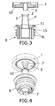
- FIG. 4 shows now the lower element (69 has been provided with a duct or tubular connection (7) which permits connection from the interior of the bottle with the exterior.
Landscapes
- Engineering & Computer Science (AREA)
- Mechanical Engineering (AREA)
- Closures For Containers (AREA)
- Infusion, Injection, And Reservoir Apparatuses (AREA)
Abstract
Pouring cap which is provided with an upper element or closing cap of a lower element attached to a bottle neck, where this lower element is provided with at least one retractable tube with means of attachment between the upper end of the retractable tube and an elevation of a tubular ring projection on the closing cap, in this way obtaining a pouring cap which is provided with a pouring tube which in addition takes up Little height and may be manufactured automatically.
Description
- The object of this invention is a pouring cap which has the particularity that it is provided with an integrated tube in addition to a threaded closing cap in the pouring cap arrangement.
- The invention is characterised by the special configuration of the design of the parts which make up the pouring cap so that a cap is obtained which is provided with a pouring tube which is retractable, and which is covered by a threaded cap, having a reduced height.
- Therefore, this invention is circumscribed within the scope of pouring caps, and in particular those which are provided with a retractable tube.
- To date, bottles especially wine bottles, have had a cork cap with two holes on which respective tubes where arranged, one of the tubes being designed for pouring whereas the other served to facilitate entry of air to the inside of the bottle.
- Recently, in some oil and vinegar bottles, a pouring cap is added which comprises at least one tube for pouring the liquid, and at times another duct for the entry of air. However, this constructive solution of combining a pouring tube with a cap considerably increases the height of the pouring cap which hinders its packaging.
- The applicant is aware of another cap which is provided with an extractable tube which permits reduction of the height of the pouring cap arrangement by means of incorporating a tube which is extracted by a spring which is activated when the upper cap is unscrewed.
- Although this solution satisfies the requirements of pouring and reduced height, it has various disadvantages deriving from the complexity of the system which makes it complicated to assemble, as it is not possible to automatically arrange a spring and a tube against the action of a spring, thus these caps need to be assembled by hand. This means of manufacture leads to high production costs. Furthermore, said form of assembly is not permitted for hygiene reasons as it necessitates contact with bottle caps to be used for food purposes.
- Therefore, this invention develops a pouring cap which is addition to having a retractable tube, and a cap with and arrangement which is reduced in height, may be manufactured automatically, without needing to be assembled manually, as occurs with the previous pouring cap described.
- This invention of a pouring cap with retractable tube basically consists of an upper element or cap which, through screwing, closes the lower element on which a retractable tube is fitted.
- Said tube is extractable due to cooperation of the constructive characteristics of both the upper element or cap, and those of the tube, so that following unscrewing of the cap and removal, a tube is simultaneously extracted. Said extraction is limited up to a certain point. The retraction of the tube to its contained position is made simply by pushing the tube.
- In order to ensure that the retractable tube and the closing cap are linked and that it is possible to extract the tube, there is a ring projection on the cap of tubular section which is provided close to its free end with a ring elevation, whereas on the upper end of the retractable tube close to the end and in the lower part of the tube there is a hollow or recess into which the ring projection of the closing cap fits.
- The upper element or closing cap is required to have means of coupling and attachment to the bottle neck. Said means of coupling between the upper element or the closing cap may be made directly through complementary and antagonistic means of screwing, arranged both on the upper element and the lower element which is affixed to the bottle or indirectly through a metal capsule.
- When the coupling between the upper element or closing cap and the lower element is made through a metal capsule, the upper element or closing cap fits on the base of a metal capsule, which close to its interior end is provided with a thread on its inner face which screws onto a thread arranged to this effect on the external edge of the upper end of the bottle, thus obtaining a coupling of both parts and achieving closure with the retracted tube and providing the arrangement with minimum height.
- The metal capsule would be used in those cases in which it is essential to ensure that the content remains intact ensuring that it has not been modified in any way between manufacture and the moment of opening. The means for sealing and ensuring inviolability could be any of those known in the state of the art, such as discontinuous perforation, segregated tape, etc.
- When the upper element or closing cap screws directly onto the lower element, both parts are provided with ring grooves which are threaded in their interior in a facing manner, so that the closing cap is threaded on the lower element of the arrangement, presenting the arrangement wrapped in a thermo-retractable capsule and/or metal capsule.
- Furthermore, on the external surface of the lower element, and in particular on the part which fits in the neck of the bottle, a series of flaps are arranged, inclined in such a way that insertion and retention is obtained in the neck of the bottle.
- The arrangement of these inclined flaps permits adjustment to the bottle necks with not very precise measures, however, as an alternative solution to the inclined flaps on the external surface of the lower element, a series of ring projections of resilient materials may be arranged, thus permitting improved grip.
- In addition, the pouring cap arrangement may be provided with a direct connection between the lower part of the same and the exterior in order to permit the entry of air to the interior of the bottle while at the same time emptying it.
- As a complementary solution to the arrangement of a single retractable tube, the arrangement of a series of telescopic retractable tubes is also possible, which would permit greater length of tube in the event that this were necessary.
- In order to complete the description below, and to assist in obtaining a better comprehension of its characteristics, the present descriptive report is accompanied by a set of plans with figures representing in an illustrative but not restrictive way the most significant details of the invention.
-
Figure 1 shows and upright view of the elements which make up the pouring cap arrangement which is the object of the invention. -
Figure 2 shows a ground view of the previous arrangement. -
Figure 3 shows a vertical cross section front view of the arrangement infigure 1 . -
Figure 4 , shows a perspective representation of the object of the invention. -
Figure 5 , shows a mixed representation of the front view of the pouring cap, part of which is in cross section, and shows another means for the arrangement to grip the interior of the bottle neck. - In the light of the figures below a preferred embodiment of the proposed invention is described.
-
Figure 1 shows the pouring cap which is the object of the invention which is formed by an upper element or closing cap (1) and a lower element (6). - Fitted in the interior of the lower element (6) is a retractable tube (4), which as shown in
figure 1 , is found in a maximum extraction position. - In order to achieve extraction of the retractable tube (4) both the closing cap (1) and the lower element are provided with the means for cooperation, thus in the closing cap (1) on its lower face as seen frontally, there is a ring projection with tubular section (2), which, close to its free end is provided with an external projection (3). This external projection (3) would fit in a circular recess (5) close to the upper end of the retractable tube (4), where said circular recess (5) is made on the inner face of the retractable tube (4).
- The form in which the closing cap (1) is attached to the lower element (6) may be the contrary, that is, the elevation (3) of the ring projection (2) in arranged on the interior part, whereas the circular recess (5) is made on external face of the retractable tube (4).
- Thus due to the clipping or attachment produced by the fitting of the external element (3) in the circular recess (5) when the closing cap (1) is raised the retractable tube is extracted, permitting separation of the closing cap (1) form the retractable tube (4).
- Extraction of the retractable tube (4) is not total and is restricted by a lower edge (13) with which the retractable tube is provided (4). Instead of providing a single retractable tube, various may be used, in which case they would be deployed in a telescopic manner with each section being linked to the next.
- Furthermore, in one possible embodiment and in order to close the closing cap (1) directly on the lower element, the closing cap (1) is provided in its lower face with a ring groove (10) and one of the inner faces of the groove is threaded, thus it would screw onto the thread made on a ring groove (11) made on the lower element (6).
- Another possible form of embodiment for obtaining coupling of the upper element or closing cap (1) on the lower element (6) may be made through a metal capsule, in which case the upper element or closing cap (1) is fitted on the base of said metal capsule, which is provided in the area of its lower end and its inner face with a thread complementary to another thread arranged on the external face of the upper end of the bottle neck. Due to said complementary thread, the retraction of the tube (4) would be achieved and coupling of the upper part or closing cap (1) on the lower element (6) in a position of containment of the tube with minimum height of the arrangement.
- In order to permit gripping of the lower element (6) on the bottle neck, on the lower element on its external face a series of inclined flaps (8) are arranged, oriented in such a way that they facilitate insertion of the lower element in the bottle neck and thus not its extraction.
- The arrangement of said flaps (8) permits adjustment to those bottle necks which are not provided with precise dimensions.
- As an alternative solution to gripping of the lower element (6) to the bottle neck, a series of ring discs (9) made from resilient material may be arranged on the external part of the lower element (6) as shown in
figure 5 , and which permit improved gripping and which are used when the dimensions of the bottle neck are more precise. -
Figure 4 shows now the lower element (69 has been provided with a duct or tubular connection (7) which permits connection from the interior of the bottle with the exterior. - The essential nature of this invention is not altered by any variations in materials, form, size and arrangement of its component elements, which are described in a non-restrictive manner, with this being sufficient to proceed to its reproduction by an expert.
Claims (9)
- Pouring cap with extractable tube which comprises an upper element or closing cap (1) which by means of screwing closes a lower element on which at least one retractable tube is fitted, and in which the lower element (6) is provided with means for attachment to the interior of the bottle neck, where at least one retractable tube (4) is arranged on the lower element (6) and which is characterised in that the closing cap (1) has a ring projection with tubular section (2) on its lower face, which is provided close to its free end with an elevation (3), whereas on the at least one retractable tube, (4) close to its upper end there is a circular recess (5).
- Pouring cap with extractable tube according to claim 1, characterised in that the elevation (3) is external to the ring projection with tubular section (2), whereas the circular recess is arranged on the inner face of the retractable tube.
- Pouring cap with extractable tube according to claim 1, characterised in that the elevation (3) is internal to the ring projection with tubular section (2), whereas the circular recess (5) is arranged on the external face of the extractable tube.
- Pouring tube with extractable tube according to any of claims 1-3, characterised in that the means of attachment of the lower element (6) to the interior of the bottle neck consists of a series of ring flaps arranged on the external face of the lower element.
- Pouring cap with extractable tube according to any of claims 1-3, characterised in that the means of attachment of the lower element (6) to the interior of the bottle neck consists of a series of ring discs arranged on the external part of the lower element and made with resilient material.
- Pouring cap with extractable tube according to any of claims 1-3, characterised in that in the event that it is provided with more than one retractable tube (4), these shall be deployed in a telescopic manner.
- Pouring cap with extractable tube according to nay of claims 1-3, characterised in that in order to close the closing cap (1) on the lower element (6), the closing cap (1) is provided in ins lower face with a ring groove (10) and one of the inner faces of the groove is threaded, thus it would screw onto the thread made on a ring groove (11) made on the lower element (6).
- Pouring cap with extractable tube, according to any of claims 1-3 characterised in that in order to close the closing cap (1) on the lower element (6) the closing cap (1) is fitted on the base of a metal capsule which in the area of its lower end is provided with a thread complementary to another thread arranged on the external face of the upper end of the bottle neck.
- Pouring cap with extractable tube according to any of the previous claims, characterised in that it is provided with at least one tubular connection (7) which permits connection of the interior of the bottle with the exterior.
Applications Claiming Priority (2)
| Application Number | Priority Date | Filing Date | Title |
|---|---|---|---|
| ES200803499A ES2350780B1 (en) | 2008-12-10 | 2008-12-10 | GREEN CAP WITH REMOVABLE CANNULA |
| PCT/ES2009/070498 WO2010066926A1 (en) | 2008-12-10 | 2009-11-12 | Pouring lid with retractable spout |
Publications (1)
| Publication Number | Publication Date |
|---|---|
| EP2371730A1 true EP2371730A1 (en) | 2011-10-05 |
Family
ID=41718285
Family Applications (1)
| Application Number | Title | Priority Date | Filing Date |
|---|---|---|---|
| EP09799654A Withdrawn EP2371730A1 (en) | 2008-12-10 | 2009-11-12 | Pouring lid with retractable spout |
Country Status (5)
| Country | Link |
|---|---|
| EP (1) | EP2371730A1 (en) |
| AR (1) | AR074557A1 (en) |
| CL (1) | CL2011001421A1 (en) |
| ES (1) | ES2350780B1 (en) |
| WO (1) | WO2010066926A1 (en) |
Cited By (6)
| Publication number | Priority date | Publication date | Assignee | Title |
|---|---|---|---|---|
| WO2013155127A1 (en) * | 2012-04-12 | 2013-10-17 | Funlpro Technology Llc | Container cap having an extendible pouring s pout |
| WO2014037825A1 (en) | 2012-09-10 | 2014-03-13 | Guala Closures S.P.A. | Pourer with retractable spout |
| GB2513840A (en) * | 2013-02-04 | 2014-11-12 | Mark Anthony Bradley | Improvements in or relating to container closures |
| WO2015132428A1 (en) * | 2014-05-29 | 2015-09-11 | Josep Maria Janes Autonell | Cap for non-refillable containers |
| US9550606B2 (en) | 2015-03-20 | 2017-01-24 | Funlpro Technology Llc | Detachable dispensing systems for containers |
| US10589908B2 (en) | 2017-12-01 | 2020-03-17 | Gbs Holdings Llc | Pouring spout fitment for flexible container |
Families Citing this family (4)
| Publication number | Priority date | Publication date | Assignee | Title |
|---|---|---|---|---|
| US9592944B2 (en) | 2011-08-29 | 2017-03-14 | Liqui-Box Corporation | Aseptic duckbill flip-cap fitment for a collapsible container |
| DE102016124071B3 (en) | 2016-12-12 | 2018-04-05 | Schütz GmbH & Co. KGaA | Bung POT CLOSURE |
| CN110697240B (en) * | 2019-11-15 | 2023-11-03 | 烟台金元包装材料有限公司 | Telescopic anti-theft combined cover and opening method thereof |
| CN114275312A (en) * | 2020-02-08 | 2022-04-05 | 李红彪 | Container convenient to pour |
Family Cites Families (4)
| Publication number | Priority date | Publication date | Assignee | Title |
|---|---|---|---|---|
| US1595231A (en) * | 1922-12-11 | 1926-08-10 | Edwin H Dryer | Container and spout |
| DE3542769A1 (en) * | 1985-12-04 | 1987-06-11 | Berg Jacob Gmbh Co Kg | BELLOW CLOSURE WITH INTEGRATED VENTILATION |
| FR2799739B1 (en) * | 1999-10-13 | 2002-09-06 | Pechiney Emballage Alimentaire | ERECTILE ANTI-DRIP POURER FOR CAPPING CAP |
| FR2875485B1 (en) * | 2004-09-23 | 2009-04-10 | Arc Creation Design Et Pvl Sar | LIQUID DISPENSER FOR FIXING IN THE BOTTLE OF A BOTTLE AND BOTTLE THEREFOR |
-
2008
- 2008-12-10 ES ES200803499A patent/ES2350780B1/en not_active Expired - Fee Related
-
2009
- 2009-11-12 WO PCT/ES2009/070498 patent/WO2010066926A1/en not_active Ceased
- 2009-11-12 EP EP09799654A patent/EP2371730A1/en not_active Withdrawn
- 2009-12-09 AR ARP090104759A patent/AR074557A1/en active IP Right Grant
-
2011
- 2011-06-10 CL CL2011001421A patent/CL2011001421A1/en unknown
Non-Patent Citations (1)
| Title |
|---|
| See references of WO2010066926A1 * |
Cited By (11)
| Publication number | Priority date | Publication date | Assignee | Title |
|---|---|---|---|---|
| WO2013155127A1 (en) * | 2012-04-12 | 2013-10-17 | Funlpro Technology Llc | Container cap having an extendible pouring s pout |
| US9056699B2 (en) | 2012-04-12 | 2015-06-16 | Funlpro Technology Llc | Pouring spout for container |
| WO2014037825A1 (en) | 2012-09-10 | 2014-03-13 | Guala Closures S.P.A. | Pourer with retractable spout |
| US10099826B2 (en) | 2012-09-10 | 2018-10-16 | Guala Closures S.P.A. | Pourer with retractable spout |
| GB2513840A (en) * | 2013-02-04 | 2014-11-12 | Mark Anthony Bradley | Improvements in or relating to container closures |
| GB2513840B (en) * | 2013-02-04 | 2015-08-05 | Mark Anthony Bradley | Container with irremovable closure to facilitate dispensation of contents |
| WO2015132428A1 (en) * | 2014-05-29 | 2015-09-11 | Josep Maria Janes Autonell | Cap for non-refillable containers |
| US9550606B2 (en) | 2015-03-20 | 2017-01-24 | Funlpro Technology Llc | Detachable dispensing systems for containers |
| US10112746B2 (en) | 2015-03-20 | 2018-10-30 | Gbs Holdings Llc | Detachable dispensing systems for containers |
| US10589908B2 (en) | 2017-12-01 | 2020-03-17 | Gbs Holdings Llc | Pouring spout fitment for flexible container |
| US10906711B2 (en) | 2017-12-01 | 2021-02-02 | Gbs Holdings Llc | Pouring spout fitment for flexible container |
Also Published As
| Publication number | Publication date |
|---|---|
| CL2011001421A1 (en) | 2012-01-13 |
| WO2010066926A1 (en) | 2010-06-17 |
| ES2350780A1 (en) | 2011-01-27 |
| ES2350780B1 (en) | 2011-11-18 |
| AR074557A1 (en) | 2011-01-26 |
Similar Documents
| Publication | Publication Date | Title |
|---|---|---|
| ES2316783T3 (en) | PLASTIC AND CAN COVER. | |
| US8276748B2 (en) | Ingredient release spout | |
| CA2473290C (en) | Container for containing two different separate products and mixing them | |
| RU2694296C2 (en) | Tamper-evident closure | |
| CA2679472C (en) | Ingredient release spout | |
| EP2321192B1 (en) | Security capsule with breakable reservoir and cutter | |
| US9592940B2 (en) | Ingredient release spout | |
| AU2017304110B2 (en) | Closure with tamper-evident band | |
| AU2014267212A1 (en) | Container closure with retractable pouring spout | |
| US9694948B1 (en) | Closure device for bottle | |
| JP5626779B2 (en) | Container with stopper during transition | |
| ES2350780A1 (en) | Pouring lid with retractable spout | |
| EP2266883A1 (en) | Closure for a liquid container | |
| US3419172A (en) | Closure system for containers | |
| US20170275064A1 (en) | Pourer of a container | |
| JP4697729B2 (en) | Cap with inner plug | |
| KR102129065B1 (en) | Structure of Outlet within Inner-Cap | |
| EP3296222A1 (en) | A cap for a food package | |
| CN101417721A (en) | Tearing and pulling type destructive bottle anti-conterfeit bottle cap and bottle mouth thereof | |
| ES1075136U (en) | Receptacle for containing two different products separately and for mixing thereof | |
| JP3932580B2 (en) | Outlet plug with built-in opening blade | |
| ITGE20090035A1 (en) | "SEALING ASSEMBLY OF A METAL CONTAINER FORMED BY A CLOSURE AND ITS LID CONTAINER" | |
| JP5198888B2 (en) | Pouring cap | |
| DE102009036839A1 (en) | Drinking container i.e. glass, for containing white beer, has foam production arrangement provided at closure element and/or in container, where arrangement has hollow body area with opening lying in beverage | |
| EP1318948B1 (en) | A capsule for closing containers |
Legal Events
| Date | Code | Title | Description |
|---|---|---|---|
| PUAI | Public reference made under article 153(3) epc to a published international application that has entered the european phase |
Free format text: ORIGINAL CODE: 0009012 |
|
| 17P | Request for examination filed |
Effective date: 20110627 |
|
| AK | Designated contracting states |
Kind code of ref document: A1 Designated state(s): AT BE BG CH CY CZ DE DK EE ES FI FR GB GR HR HU IE IS IT LI LT LU LV MC MK MT NL NO PL PT RO SE SI SK SM TR |
|
| DAX | Request for extension of the european patent (deleted) | ||
| 17Q | First examination report despatched |
Effective date: 20131106 |
|
| STAA | Information on the status of an ep patent application or granted ep patent |
Free format text: STATUS: THE APPLICATION IS DEEMED TO BE WITHDRAWN |
|
| 18D | Application deemed to be withdrawn |
Effective date: 20140318 |