EP2891960A1 - Touch panel - Google Patents
Touch panel Download PDFInfo
- Publication number
- EP2891960A1 EP2891960A1 EP13840508.9A EP13840508A EP2891960A1 EP 2891960 A1 EP2891960 A1 EP 2891960A1 EP 13840508 A EP13840508 A EP 13840508A EP 2891960 A1 EP2891960 A1 EP 2891960A1
- Authority
- EP
- European Patent Office
- Prior art keywords
- touch panel
- line
- floating electrode
- lines
- controller
- Prior art date
- Legal status (The legal status is an assumption and is not a legal conclusion. Google has not performed a legal analysis and makes no representation as to the accuracy of the status listed.)
- Withdrawn
Links
Images




Classifications
-
- G—PHYSICS
- G06—COMPUTING OR CALCULATING; COUNTING
- G06F—ELECTRIC DIGITAL DATA PROCESSING
- G06F3/00—Input arrangements for transferring data to be processed into a form capable of being handled by the computer; Output arrangements for transferring data from processing unit to output unit, e.g. interface arrangements
- G06F3/01—Input arrangements or combined input and output arrangements for interaction between user and computer
- G06F3/03—Arrangements for converting the position or the displacement of a member into a coded form
- G06F3/041—Digitisers, e.g. for touch screens or touch pads, characterised by the transducing means
- G06F3/0416—Control or interface arrangements specially adapted for digitisers
- G06F3/04164—Connections between sensors and controllers, e.g. routing lines between electrodes and connection pads
-
- G—PHYSICS
- G06—COMPUTING OR CALCULATING; COUNTING
- G06F—ELECTRIC DIGITAL DATA PROCESSING
- G06F3/00—Input arrangements for transferring data to be processed into a form capable of being handled by the computer; Output arrangements for transferring data from processing unit to output unit, e.g. interface arrangements
- G06F3/01—Input arrangements or combined input and output arrangements for interaction between user and computer
- G06F3/03—Arrangements for converting the position or the displacement of a member into a coded form
- G06F3/041—Digitisers, e.g. for touch screens or touch pads, characterised by the transducing means
- G06F3/0416—Control or interface arrangements specially adapted for digitisers
- G06F3/0418—Control or interface arrangements specially adapted for digitisers for error correction or compensation, e.g. based on parallax, calibration or alignment
-
- G—PHYSICS
- G06—COMPUTING OR CALCULATING; COUNTING
- G06F—ELECTRIC DIGITAL DATA PROCESSING
- G06F3/00—Input arrangements for transferring data to be processed into a form capable of being handled by the computer; Output arrangements for transferring data from processing unit to output unit, e.g. interface arrangements
- G06F3/01—Input arrangements or combined input and output arrangements for interaction between user and computer
- G06F3/03—Arrangements for converting the position or the displacement of a member into a coded form
- G06F3/041—Digitisers, e.g. for touch screens or touch pads, characterised by the transducing means
- G06F3/044—Digitisers, e.g. for touch screens or touch pads, characterised by the transducing means by capacitive means
-
- G—PHYSICS
- G06—COMPUTING OR CALCULATING; COUNTING
- G06F—ELECTRIC DIGITAL DATA PROCESSING
- G06F3/00—Input arrangements for transferring data to be processed into a form capable of being handled by the computer; Output arrangements for transferring data from processing unit to output unit, e.g. interface arrangements
- G06F3/01—Input arrangements or combined input and output arrangements for interaction between user and computer
- G06F3/03—Arrangements for converting the position or the displacement of a member into a coded form
- G06F3/041—Digitisers, e.g. for touch screens or touch pads, characterised by the transducing means
- G06F3/044—Digitisers, e.g. for touch screens or touch pads, characterised by the transducing means by capacitive means
- G06F3/0445—Digitisers, e.g. for touch screens or touch pads, characterised by the transducing means by capacitive means using two or more layers of sensing electrodes, e.g. using two layers of electrodes separated by a dielectric layer
-
- G—PHYSICS
- G06—COMPUTING OR CALCULATING; COUNTING
- G06F—ELECTRIC DIGITAL DATA PROCESSING
- G06F3/00—Input arrangements for transferring data to be processed into a form capable of being handled by the computer; Output arrangements for transferring data from processing unit to output unit, e.g. interface arrangements
- G06F3/01—Input arrangements or combined input and output arrangements for interaction between user and computer
- G06F3/03—Arrangements for converting the position or the displacement of a member into a coded form
- G06F3/041—Digitisers, e.g. for touch screens or touch pads, characterised by the transducing means
- G06F3/044—Digitisers, e.g. for touch screens or touch pads, characterised by the transducing means by capacitive means
- G06F3/0446—Digitisers, e.g. for touch screens or touch pads, characterised by the transducing means by capacitive means using a grid-like structure of electrodes in at least two directions, e.g. using row and column electrodes
-
- G—PHYSICS
- G06—COMPUTING OR CALCULATING; COUNTING
- G06F—ELECTRIC DIGITAL DATA PROCESSING
- G06F3/00—Input arrangements for transferring data to be processed into a form capable of being handled by the computer; Output arrangements for transferring data from processing unit to output unit, e.g. interface arrangements
- G06F3/01—Input arrangements or combined input and output arrangements for interaction between user and computer
- G06F3/03—Arrangements for converting the position or the displacement of a member into a coded form
- G06F3/041—Digitisers, e.g. for touch screens or touch pads, characterised by the transducing means
- G06F3/047—Digitisers, e.g. for touch screens or touch pads, characterised by the transducing means using sets of wires, e.g. crossed wires
-
- G—PHYSICS
- G09—EDUCATION; CRYPTOGRAPHY; DISPLAY; ADVERTISING; SEALS
- G09G—ARRANGEMENTS OR CIRCUITS FOR CONTROL OF INDICATING DEVICES USING STATIC MEANS TO PRESENT VARIABLE INFORMATION
- G09G5/00—Control arrangements or circuits for visual indicators common to cathode-ray tube indicators and other visual indicators
- G09G5/003—Details of a display terminal, the details relating to the control arrangement of the display terminal and to the interfaces thereto
-
- G—PHYSICS
- G09—EDUCATION; CRYPTOGRAPHY; DISPLAY; ADVERTISING; SEALS
- G09G—ARRANGEMENTS OR CIRCUITS FOR CONTROL OF INDICATING DEVICES USING STATIC MEANS TO PRESENT VARIABLE INFORMATION
- G09G2300/00—Aspects of the constitution of display devices
- G09G2300/04—Structural and physical details of display devices
- G09G2300/0421—Structural details of the set of electrodes
- G09G2300/0426—Layout of electrodes and connections
-
- H—ELECTRICITY
- H05—ELECTRIC TECHNIQUES NOT OTHERWISE PROVIDED FOR
- H05K—PRINTED CIRCUITS; CASINGS OR CONSTRUCTIONAL DETAILS OF ELECTRIC APPARATUS; MANUFACTURE OF ASSEMBLAGES OF ELECTRICAL COMPONENTS
- H05K1/00—Printed circuits
- H05K1/18—Printed circuits structurally associated with non-printed electric components
- H05K1/189—Printed circuits structurally associated with non-printed electric components characterised by the use of flexible or folded printed circuits
-
- H—ELECTRICITY
- H05—ELECTRIC TECHNIQUES NOT OTHERWISE PROVIDED FOR
- H05K—PRINTED CIRCUITS; CASINGS OR CONSTRUCTIONAL DETAILS OF ELECTRIC APPARATUS; MANUFACTURE OF ASSEMBLAGES OF ELECTRICAL COMPONENTS
- H05K2201/00—Indexing scheme relating to printed circuits covered by H05K1/00
- H05K2201/05—Flexible printed circuits [FPCs]
- H05K2201/052—Branched
-
- H—ELECTRICITY
- H05—ELECTRIC TECHNIQUES NOT OTHERWISE PROVIDED FOR
- H05K—PRINTED CIRCUITS; CASINGS OR CONSTRUCTIONAL DETAILS OF ELECTRIC APPARATUS; MANUFACTURE OF ASSEMBLAGES OF ELECTRICAL COMPONENTS
- H05K2201/00—Indexing scheme relating to printed circuits covered by H05K1/00
- H05K2201/09—Shape and layout
- H05K2201/09209—Shape and layout details of conductors
- H05K2201/09654—Shape and layout details of conductors covering at least two types of conductors provided for in H05K2201/09218 - H05K2201/095
- H05K2201/09781—Dummy conductors, i.e. not used for normal transport of current; Dummy electrodes of components
-
- H—ELECTRICITY
- H05—ELECTRIC TECHNIQUES NOT OTHERWISE PROVIDED FOR
- H05K—PRINTED CIRCUITS; CASINGS OR CONSTRUCTIONAL DETAILS OF ELECTRIC APPARATUS; MANUFACTURE OF ASSEMBLAGES OF ELECTRICAL COMPONENTS
- H05K2201/00—Indexing scheme relating to printed circuits covered by H05K1/00
- H05K2201/10—Details of components or other objects attached to or integrated in a printed circuit board
- H05K2201/10007—Types of components
- H05K2201/10128—Display
Definitions
- the present invention relates to a touch panel that can determine a touch position on the operation surface.
- Touch panels that can determine the position at which a stylus or finger touches the operation surface, i.e. a touch position, are known.
- a touch panel includes two types of electrodes extending in different directions, where one group of electrodes straddle the other group of electrodes. That is, each of the electrodes of the one group has first portions that each straddle an electrode of the other group.
- JP 2012-123850 A discloses a shielding conductive film located in the same layer as the first portions of the electrodes of the one group. This conductive film covers the electrodes of the two types in plan view. This conductive film may be electrically connected with a line of a reference potential, for example, to allow a certain signal to enter the conductive film, thereby reducing noise produced in the touch panel by a liquid crystal display panel placed over the touch panel.
- a touch panel includes lead lines located outside the region of the touch electrodes and electrically connected with the touch electrodes. If the panel includes two types of electrodes extending in different directions, as in the arrangement of JP 2012-123850 A , such lead lines are each connected with the corresponding one of the electrodes, which means that the panel includes a large number of such lines.
- a touch panel is connected with an external control substrate or the like via connection lines and, for this purpose, the lead lines of each group are gathered at one location on the substrate of the touch panel. The location at which the lead lines of each group are gathered requires a space to accommodate all of these lead lines, resulting in a touch panel with a large picture frame region around the region of the electrodes. This means an increased size of the touch panel.
- the lead lines of one group may be gathered at two or more separate locations on the substrate of the touch panel.
- each of the locations on the substrate at which these lead lines are gathered requires a smaller space for accommodating the lead lines, resulting in a touch panel with a smaller picture frame region.
- some lead lines are separated from each other at a larger distance.
- a signal that has been output by a touch panel may contain some noise due to external influence.
- the difference between signals in two adjacent lead lines may be determined to remove noise contained in the signals in the lead lines. If this differential approach is to be used to remove noise, the distance between one lead line and an adjacent one must be constant such that a uniform level of noise is present in each lead line. However, if some lead lines are separated from each other at a larger distance, noise in these lead lines cannot be sufficiently removed by the differential approach.
- An object of the present invention is to provide an arrangement that uses the differential approach to effectively remove noise contained in a signal transmitted via a line even in a touch panel that includes some lines that are separated from each other at a larger distance.
- a touch panel includes: a substrate; a plurality of electrodes provided on the substrate; a plurality of lines each electrically connected with one of the plurality of electrodes; a controller configured to determine the difference between a signal provided by at least one line out of the plurality of lines and a signal provided by another line adjacent the at least one line out of the plurality of lines; and a floating electrode located within a predetermined distance from the at least one line and the other line and electrically independent from the plurality of lines such that noise produced in the at least one line can be propagated to reach the other line.
- the touch panel according to an embodiment of the present invention uses the differential approach to effectively reduce noise contained in a signal transmitted via a line even if some lines are separated from each other at a larger distance.
- a touch panel includes: a substrate; a plurality of electrodes provided on the substrate; a plurality of lines each electrically connected with one of the plurality of electrodes; a controller configured to determine the difference between a signal provided by at least one line out of the plurality of lines and a signal provided by another line adjacent the at least one line out of the plurality of lines; and a floating electrode located within a predetermined distance from the at least one line and the other line and electrically independent from the plurality of lines such that noise produced in the at least one line can be propagated to reach the other line (first arrangement).
- floating electrode means an electrode that is electrically independent from the lines and is in a state without any signal input.
- Predetermined distance means a distance that allows noise to be propagated between a line and the floating electrode.
- the touch panel may further include a connecting portion configured to electrically connect the substrate with the controller.
- Each of the plurality of lines may include a substrate line provided on the substrate and electrically connected with one of the plurality of electrodes, a connection line provided on the connecting portion, and a controller line provided in the controller.
- the substrate line, the connection line and the controller line may be electrically connected.
- the floating electrode may be located within the predetermined distance from at least one line out of the substrate line, the connection line and the controller line, and another line adjacent the at least one line out of the plurality of lines (second arrangement).
- signal noise produced in a line may be propagated through the floating electrode to reach the next line.
- noise may be removed by the differential approach.
- the floating electrode may be loop-shaped (third arrangement). This will further ensure that signal noise is propagated between two adjacent lines via the floating electrode.
- the floating electrode may be located in the substrate, the connecting portion and the controller (fourth arrangement).
- signal noise may be propagated between two adjacent lines in the substrate, connecting portion and controller. This further ensures that the differential approach removes signal noise.
- the floating electrode may be located to at least partly overlap at least one line out of the substrate line, the connection line and the controller line and another line adjacent the at least one line out of the plurality of lines, as viewed in a thickness direction of the substrate (fifth arrangement).
- the parasitic capacitance formed by capacitive coupling between a line and the floating electrode is increased over that for an arrangement where the line and floating electrode are located in the same plane. This allows noise from a line to propagate through the floating electrode to reach the adjacent line more effectively.
- the floating electrode has the same width as the at least one line and the other line.
- the minimum distance between the floating electrode and the at least one line next to the floating electrode is substantially equal to the minimum distance between the floating electrode and the other line adjacent the floating electrode.
- the propagation characteristics for noise from a line with noise to the floating electrode are substantially the same as the propagation characteristics for noise from the floating electrode to the adjacent line.
- connection lines are divided into at least two line groups near their connection with the substrate and the floating electrode extends from the branch position of the line groups along the line groups.
- a floating electrode extending from the branch position of line groups of connection lines along the line groups allows signal noise produced in one line group to propagate through the floating electrode to reach the other line group.
- signal noise produced in one connection line is propagated through the floating electrode to reach the other connection line.
- FIG. 1 is a schematic view of a touch panel-equipped liquid crystal display device 1 (i.e. touch panel-equipped display device) including a touch panel 2 according to Embodiment 1.
- a panel body 2a of a touch panel 2 that can determine a touch position is placed over a liquid crystal panel 3 that can display an image.
- numeral 4 indicates a cover glass located on the side of the touch panel 2 that is opposite the one adjacent the liquid crystal panel 3 (i.e. the operation surface side or the viewer's side).
- Numeral 5 indicates a touch panel controller (i.e. controller) that constitutes part of the touch panel 2 and controls the operation of the panel body 2a.
- the backlight and other components stacked on the liquid crystal panel 3 are not shown.
- the liquid crystal panel 3 includes an active-matrix substrate having a large number of pixels arranged in a matrix, a counter-substrate having a surface facing the active-matrix substrate, and a liquid crystal layer located between the active-matrix substrate and counter-substrate.
- the construction of the liquid crystal panel 3 is the same as that of conventional liquid crystal panels and thus will not be described in detail.
- the panel body 2a of the touch panel 2 includes two panel portions stacked on top of each other in its thickness direction. More specifically, as shown in FIG. 2 , the panel body 2a includes an X-direction touch panel portion 11 having a plurality of X-direction electrodes 13 extending in the X direction, and a Y-direction touch panel portion 21 having a plurality of Y-direction electrodes 23 extending in the Y direction. In the present embodiment, as shown in FIG. 1 , these panel portions are stacked on top of each other, beginning from the bottom in the order of X-direction touch panel portion 11 and then Y-direction touch panel portion 21 in the thickness direction thereof:
- the X-direction touch panel portion 11 and Y-direction touch panel portion 12 are stacked on top of each other in the thickness direction thereof such that the X-direction electrodes 13 cross the Y-direction electrodes 23, as shown in FIG. 2 .
- a predetermined voltage is applied to the X-direction electrodes 12.
- the panel body 2a of the touch panel 2 is constructed from two panels stacked on top of each other in the thickness direction thereof; however, the present invention is not limited to such a construction, and a layer of X-direction electrodes and a layer of Y-direction electrodes may be stacked on each other in the thickness direction thereof inside a single panel.
- the X-direction touch panel portion 11 includes a touch panel substrate 12 made of resin and generally rectangular X-direction electrodes 13 (indicated by broken lines in FIG. 2 ) on the touch panel substrate 12 extending in the X direction.
- the touch panel substrate 12 is generally rectangular in shape, with its long sides extending in the X direction.
- a plurality of parallel X-direction electrodes 13 are arranged in the Y direction on the touch panel substrate 12. That is, the X-direction electrodes 13 extend in the longitudinal direction of the touch panel substrate 12.
- the X-direction touch panel portion 11 further includes a plurality of lead lines 14 (i.e. lines) provided on the touch panel substrate 12 and electrically connected with the X-direction electrodes 13.
- Each of the lead lines 14 has one end connected with one of the ends of an X-direction electrode 13 disposed in its longitudinal direction.
- the lead lines 14 are provided on the touch panel substrate 12 such that they have the other ends gathered at one location toward one of the ends of the touch panel substrate 12 disposed in its longitudinal direction.
- a flexible print substrate (hereinafter referred to as FPC) 31 is connected with the other ends of the lead lines 14 provided on the touch panel substrate 12, i.e. the one of the ends of the touch panel substrate 12 disposed in its longitudinal direction.
- the FPC 31 includes a flexible substrate made of resin that has a plurality of lines corresponding to the lead lines 14.
- the FPC 31 is also electrically connected with the touch panel controller 5, described below.
- the Y-direction touch panel portion 21 includes a touch panel substrate (i.e. substrate) 22 made of resin and generally rectangular Y-direction electrodes 23 on the touch panel substrate 22 extending in the Y direction. Similar to the touch panel substrate 12 of the X-direction touch panel portion 11, the touch panel substrate 22 is generally rectangular in shape with its long sides extending in the X direction. A plurality of parallel Y-direction electrodes 23 are arranged in the X direction on the touch panel substrate 22. That is, the Y-direction electrodes 23 extend toward one long side of the touch panel substrate 22.
- the Y-direction touch panel portion 21 further includes a plurality of lead lines 24 (i.e. substrate lines, lines) provided on the touch panel substrate 22 and electrically connected with the Y-direction electrodes 23.
- Each of the lead lines 24 has one end connected with one of the ends of a Y-direction electrode 23 disposed in its longitudinal direction.
- the lead lines 24 are provided on the touch panel substrate 22 such that they have the other ends gathered at two separate locations toward one long side of the touch panel substrate 22.
- the space required to accommodate the lead lines 24 is smaller than when all of them are gathered at a single location. That is, if the plurality of lead lines 24 are to be gathered at a single location, the plurality of lead lines 24 must be disposed parallel near one long side of the touch panel substrate 22, resulting in a touch panel substrate 22 with large short sides. This means a touch panel substrate 22 with a large region where the Y-direction electrodes 23 are not present (i.e. picture frame region), increasing the size of the substrate itself.
- the lead lines 24 are gathered at two separate locations, the number of lead lines 24 disposed parallel near one long side of the touch panel substrate 22 is smaller than when all of them are gathered at one location. This reduces the length of the short sides of the touch panel substrate 22, reducing the size of the entire Y-direction touch panel portion 21.
- some lead lines, 24a and 24b are separated from each other at a larger distance, as is apparent from FIG. 2 . A larger distance between the lead lines 24a and 24b causes an increase in the variation of noise contained in a signal. This point will be discussed further below.
- an FPC 32 is connected with the other ends of the lead lines 24 provided on the touch panel substrate 22, i.e. one long side of the touch panel substrate 22.
- the FPC 32 includes a flexible substrate 33 made of resin and a plurality of connection lines 34 provided on the flexible substrate 33 corresponding to the lead lines 24.
- the FPC 32 has one end forked into two branches that are to be electrically connected with the respective groups of the other ends of the lead lines. That is, the FPC 32, which has one end forked into two, includes a plurality of connection lines 34 divided into two line groups 35 and 36. Further, the FPC 32 has the other end electrically connected with the touch panel controller 5, described below. The other end of the FPC 32, which is connected with the touch panel controller 5, is not forked into two, and is in the shape of a generally rectangular strip.
- connection lines 34a and 34b which are adjacent each other at the other end of the FPC 32, are separated at a large distance at the one end of the FPC, where the FPC is forked into two (see FIG. 4 ).
- the construction of the lead lines 24 on the touch panel substrate 22 and the FPC 32 will be described in detail further below.
- the FPCs 31 and 32 are electrically connected with the touch panel controller 5. That is, the X-direction touch panel portion 11 and Y-direction touch panel portion 21 of the touch panel 2 are electrically connected with the touch panel controller 5.
- the lead lines 24 and connection lines 34 constitute lines 6 connected with the electrodes.
- the touch panel controller 5 of the present embodiment applies a predetermined voltage to the X-direction touch panel portion 11 and detects output signals from the Y-direction touch panel portion 21. That is, the touch panel controller 5 detects, as an output signal from the Y-direction touch panel portion 21, a change in the electrostatic capacitance between an X-direction electrode 13 and Y-direction electrode 23 encountered when a finger or the like of the operator touches the panel body 2a of the touch panel 2. Based on the output signal from the Y-direction touch panel portion 21, the touch panel controller 5 determines the touch position on the panel body 2a.
- the touch panel controller 5 is configured to perform differential noise removal. Differential noise removal involves determining the difference between a signal provided by one electrode and a signal provided by another electrode to remove the noise contained in the signals. The touch panel controller 5 determines the difference between output signals from two adjacent Y-direction electrodes 23 to remove the noise contained in these output signals.
- the touch panel controller 5 includes a subtracter 51 for determining the difference between signals provided by two adjacent Y-direction electrodes 23 of the Y-direction touch panel portion 21, and a position detector 52 for determining the touch position based on the difference calculated by the subtracter 51.
- the subtracter 51 subtracts a signal provided by one Y-direction electrode 23 from a signal provided by an adjacent Y-direction electrode 23 to determine the difference between these signals. This removes noise present in the Y-direction electrodes 23 and, at the same time, determines the increase in the electrostatic capacitance at the touch position in the form of the difference between Y-direction electrodes 23.
- the position detector 52 Based on the difference determined by the subtracter 51, the position detector 52 detects that the position where the difference rapidly increases is the touch position. When the position detector 52 determines the touch position, it provides the touch position as a positional signal (i.e. detection signal).
- Differential noise cancelling discussed above is effective when signals transmitted via two lines for which a signal difference is to be determined contain the same level of noise. That is, if not the same level of noise is contained in signals transmitted via the two lines, determining the difference between the signals may not effectively remove the noise contained in the signals.
- the lead lines 24 connected with the Y-direction electrodes 23 are gathered at two separate locations, some lead lines 24 are separated at a large distance. That is, as shown in FIG. 2 , the lead lines 24a and 24b connected with adjacent Y-direction electrodes 23 are separated at a large distance if the lead line 24a is located at one of the locations and the adjacent lead line 24b is located at the other location.
- a loop-shaped floating electrode 61 is provided at a position where the FPC 32 is connected with the lead lines 24 connected with the Y-direction electrodes 23.
- This floating electrode 61 is electrically independent from the lead lines 24 and is electrically independent from the connection lines 34 of the FPC 32. Further, the floating electrode 61 of the present embodiment has no voltage applied nor is it grounded.
- the floating electrode 61 includes an FPC floating electrode portion 62 provided on the flexible substrate 33 of the FPC 32 and a panel floating electrode portion 63 provided on the touch panel substrate 22 of the Y-direction touch panel portion 21.
- the FPC floating electrode portion 62 is located where the flexible substrate 33 is forked into two, and is located inwardly of the flexible substrate 33 as measured in the width direction thereof so as to extend along the forked substrate. That is, the FPC floating electrode portion 62 is located within a predetermined distance from the connection lines 34a and 34b.
- the panel floating electrode portion 63 is located between the lead lines 24a and 24b and within a predetermined distance from the lead lines 24a and 24b and is provided such that it is electrically connected with the FPC floating electrode portion 62 when the FPC 32 is connected with the Y-direction touch panel portion 21.
- the floating electrode 61 is generally pentagonal in shape.
- predetermined distance means a distance that allows noise to propagate between a line and the floating electrode. More specifically, the predetermined distance is preferably smaller than twice the gap (or pitch) between lines (i.e. the connection lines 34a and 34b and lead lines 24a and 24b in the present embodiment), and more preferably as large as the gap.
- This floating electrode 61 allows noise produced in one of the lead lines 24a and 24b to be transmitted to the other line through the floating electrode 61. That is, as indicated by arrows with broken lines in FIG. 5 , noise produced in one of the lines (i.e. lead line 24a) is transmitted to the floating electrode 61 by dielectric effects. As discussed above, the floating electrode 61 is electrically independent from the other lines (i.e. lead lines 24a and 24b) such that noise can be propagated from the floating electrode 61 by dielectric effects to reach the other line (i.e. lead line 24b), located within the predetermined distance from the floating electrode.
- the floating electrode 61 ensures that the same level of noise is contained in signals transmitted in the separated lead lines 24a and 24b.
- the above differential approach effectively removes signal noise.
- the above floating electrode 61 allows noise produced in one of the connection lines 34a and 34b of the FPC 32 to be transmitted to the other line via the floating electrode 61, as is the case with the noise in the lead line 24a or 24b.
- the above differential approach effectively removes noise produced in the FPC 32.
- the floating electrode 61 has a substantially uniform width throughout the circumference. Further, the floating electrode 61 has a width substantially equal to the width of the lead lines 24a and 24b. Further, in the FPC floating electrode portion 62 of the floating electrode 61, the left and right lengths between the branch position of the FPC 32 and the positions where the connection lines 34a and 34b become generally parallel in FIG. 4 (i.e. the lengths of the diagonal portions in the drawing) are equal to each other. Further, the minimum distances between the floating electrode 61 and the lead lines 24a and 24b and connection lines 34a and 34b are equal to each other.
- the propagation characteristics of signal noise in the left portion of the floating electrode 61 with respect to the branch position are the same as those in the right portion of the floating electrode.
- the floating electrode 61 further ensures that the same level of noise is contained in signals in the lead lines 24a and 24b and in signals in the connection lines 34a and 34b.
- Some portions of the floating electrode 61 may have a different width from the others, or the lengths from the branch position of the FPC 32 to the lead lines 24a and 24b may be different. Further, the minimum distances between the floating electrode 61 and lead lines 24a and 24b and connection lines 34a and 34b may be different.
- the present embodiment provides a floating electrode 61 between separated lead lines 24a and 24b on the touch panel substrate 22 and electrically independent from these lead lines 24a and 24b, located within a predetermined distance from these lines. This allows noise produced in one of the lead lines to be propagated via the floating electrode 61 to reach the other lead line.
- the present embodiment provides the floating electrode 61 at the forked end of the FPC 32 and between the separated connection lines 34a and 34b within a predetermined distance from these lines. Thus, noise produced in one of the connection line is propagated via the floating electrode 61 to reach the other connection line.
- the floating electrode 61 is loop-shaped so as to be located in the Y-direction touch panel portion 21 and FPC 32.
- signal noise produced in any one of the lead lines 24a and 24b on the Y-direction touch panel portion 21 and the connection lines 34a and 34b of the FPC 32 can be propagated via the floating electrode 61 to reach another line.
- the differential approach effectively removes noise contained in signals.
- FIG. 6 schematically shows a touch panel 100 according to Embodiment 2 of the present invention.
- This embodiment is different from Embodiment 1 in that a touch panel controller 103 is electrically connected with the Y-direction touch panel portion 21 via two FPCs 101 and 102.
- the components that are the same as the corresponding ones of Embodiment 1 are labeled with the same reference numerals and will not be described, and only the differences from Embodiment 1 will be described.
- the touch panel controller 103 includes a controller substrate 131 made of resin, a plurality of controller lines 132 (i.e. lines) provided on the controller substrate 131, and a controller element 133 mounted on the controller substrate 131.
- the controller element 133 is electrically connected with the plurality of controller lines 132.
- the controller element 133 functions as a controller for controlling the operation of the touch panel 100.
- the plurality of controller lines 132 are provided on the controller substrate 131 such that each of them has one end and the other end, the one ends being gathered at two separate locations.
- the plurality of controller lines 132 provided on the controller substrate 131 of the touch panel controller 103 are electrically connected with the respective lead lines 24 provided on the Y-direction touch panel portion 21 via two FPCs 101 and 102.
- the FPCs 101 and 102 are generally rectangular in shape. Similar to the FPC 32 of Embodiment 1, each of the FPCs 101 and 102 includes a flexible substrate 111 or 112 made of resin and a plurality of connection lines 113 or 114 (i.e. lines) provided on the flexible substrate 111 or 112.
- the connection lines 113 and 114 are provided on the generally rectangular flexible substrates 111 and 112 in the form of straight lines.
- the connection lines 113 and 114 electrically connect the lead lines 24 of the Y-direction touch panel portion 21 with the controller lines 132 of the touch panel controller 103.
- the FPCs 101 and 102 are separated from each other.
- the connection lines 113a of the FPC 101 are separated from the connection lines 114a of the FPC 102.
- noise produced in a connection line of one group cannot easily be propagated to reach a connection line of the other group. This may cause a difference in the level of signal noise between two adjacent lines such that the differential approach may not effectively remove noise of the signals.
- the present embodiment provides a generally rectangular floating electrode 141 located in the Y-direction touch panel portion 21, FPCs 101 and 102 and touch panel controller 103. That is, the floating electrode 141 is loop-shaped. More specifically, the floating electrode 141 includes a controller floating electrode portion 142 provided on the touch panel controller 103, FPC floating electrode portions 143 provided on the FPCs 101 and 102, and a panel floating electrode portion 144 provided on the Y-direction touch panel portion 21.
- the controller floating electrode 142 is located on the controller substrate 131 between controller lines 132a and 132b and within a predetermined distance from the controller lines 132a and 132b.
- the FPC floating electrode portions 143 are provided on the flexible substrates 111 and 112 so as to be located between connection lines 113a and 114a and within a predetermined distance from the connection lines 113a and 114a when the touch panel controller 103 is connected with the Y-direction touch panel portion 21 via the FPCs 101 and 102.
- the panel floating electrode portion 144 is provided on the touch panel substrate 22 so as to be located between lead lines 24a and 24b and within a predetermined distance from the lead lines 24a and 24b. Predetermined distance is defined similarly to that of Embodiment 1.
- the controller floating electrode portion 142, FPC floating electrode portions 143 and panel floating electrode portion 144 are provided such that they are electrically connected when the touch panel controller 103 is connected with the Y-direction touch panel portion 21 via the FPCs 101 and 102. Electrically connecting the controller floating electrode portion 142, FPC floating electrode portions 143 and panel floating electrode portion 144 forms the loop-shaped floating electrode 141.
- the Y-direction touch panel portion 21 is electrically connected with the touch panel controller 103 via two generally rectangular FPCs 101 and 102. Further, a generally rectangular floating electrode 141 is provided so as to be located in the Y-direction touch panel portion 21, FPCs 101 and 102 and touch panel controller 103 and located between two adjacent lines and within a predetermined distance from these lines.
- the floating electrode 141 ensures that the same level of noise is present in two adjacent lines, regardless of in which of the Y-direction touch panel portion 21, FPCs 101 and 102 and touch panel controller 103 noise is produced.
- the differential approach removes noise produced in a line of the touch panel 100.
- the FPC need not be forked into two as in Embodiment 1.
- FPCs of a simple shape is used, reducing the manufacturing cost.
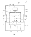
- FIGS. 7 and 8 schematically illustrate a touch panel 200 of Embodiment 3 of the present invention.
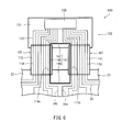
- the present embodiment is different from Embodiment 1 in that a floating electrode 204 is disposed relative to connection lines 224 and 234 of FPCs 202 and 203 and a controller line 213 of a touch panel controller 201 in the thickness direction of flexible substrates 221, 222, 231 and 232 and controller substrates 211 and 212.
- the components that are the same as the corresponding ones of Embodiment 1 or 2 are labeled with the same reference numerals and will not be described, and only the differences from Embodiment 1 or 2 will be described.
- the Y-direction touch panel portion 21 is electrically connected with the touch panel controller 201 via two FPCs 202 and 203. Further, as is the case in Embodiment 2, a panel floating electrode portion 144 is provided on the Y-direction touch panel portion 21 so as to be located on the touch panel substrate 22 between lead lines 24a and 24b.
- the touch panel controller 201 is formed by stacking two control substrates 211 and 212 in the thickness direction thereof.
- the upper side of the upper control substrate 211 has a controller line (i.e. line) 213 provided thereon and has a controller element 214 mounted thereon (see FIGS. 7 and 8 ).
- floating electrode connecting portions 215 are provided on the controller substrate 211 near their connections with the FPCs 202 and 203.
- the floating electrode connecting portions 215 are located in the region defined by the controller line 213 and near the controller line 213.
- the floating electrode connecting portions 215 are electrically connected with controller floating electrodes 216 provided on the lower controller substrate 212 via a through-hole (schematically indicated by fine broken lines in FIG. 8 ). That is, each of the floating electrode connecting portions 215 electrically connects the FPC 202 or 203 with the controller substrate 212.
- the upper side of the lower controller substrate 212 has a controller floating electrode portion 216 provided thereon.
- This controller floating electrode 216 is located to overlie the controller line 213 provided on the upper controller substrate 211 when the two controller substrates 211 and 212 are stacked on each other in the thickness direction thereof (see FIG. 7 ). That is, in the present embodiment, the controller floating electrode portion 216 is located relative to the controller line 213 in the thickness direction of the controller substrates 211 and 212.
- the controller floating electrode portion 216 is generally C-shaped as viewed in the thickness direction of the controller substrates 211 and 212 (see thick broken lines of FIG. 7 ).
- the controller floating electrode portion 216 includes through-hole connecting portions 216a each electrically connected with one of the floating electrode connecting portions 215 via a through-hole.
- Each through-hole connecting portion 216a is provided to partly overlie an electrode connecting portion 215 when the two controller substrates 211 and 212 are stacked on each other in the thickness direction thereof.
- the controller substrate 212 has such a thickness that the distance between the controller line 213 and the controller floating electrode portion 216 is within a predetermined distance.
- predetermined distance means a distance that allows noise to be propagated between a line and an electrode.
- each of the FPCs 202 and 203 is formed by stacking two flexible substrates in the thickness direction thereof.
- the FPCs 202 and 203 have the same construction except that they are mirror images of each other; thus, only the FPC 202 will be discussed in the following description.
- the FPC 202 is formed by stacking two flexible substrates 221 and 222 made of resin in the thickness direction thereof.
- the lower side of the upper flexible substrate 221 has an FPC floating electrode portion 223 provided thereon.
- This FPC floating electrode portion 223 is generally in the shape of a straight line and extends in the longitudinal direction of the FPC 202 (i.e. in the direction in which the Y-direction touch panel portion 21 and the touch panel controller 201 are connected).
- the FPC floating electrode portion 223 includes through-hole connecting portions 223a that are each to be electrically connected via a through-hole with a floating electrode connecting portion 225, discussed below, provided on the lower flexible substrate 222.
- the through-hole connecting portions 223a are provided at the locations where the FPC 202 is connected with the Y-direction touch panel portion 21 and touch panel controller 201.
- connection line i.e. line
- the connection line 224 is located to overlie the FPC floating electrode portion 223 when the two flexible substrates 221 and 222 are stacked on each other in the thickness direction thereof. Further, the connection line 224 is located to contact the controller line 213 of the FPC 202 and a lead line 24 of the Y-direction touch panel portion 21 when the FPC 202 is connected with the Y-direction touch panel portion 21 and touch panel controller 201 (see FIG. 7 ).
- the lower side of the flexible substrate 222 has floating electrode connecting portions 225 provided thereon.
- the floating electrode connecting portions 225 are provided at both ends of the flexible substrate 222 disposed in its longitudinal direction.
- Each of the floating electrode connecting portions 225 is electrically connected with one of the through-hole connecting portions 223a of the flexible substrate 221 through a through-hole.
- One of the floating electrode connecting portions 225 contacts one of the floating electrode connecting portions 215 of the touch panel controller 201 when the FPC 202 is connected with the touch panel controller 201.
- the other one of the floating electrode connecting portions 225 contacts the floating electrode 144 of the Y-direction touch panel portion 21 when the FPC 202 is connected with the Y-direction touch panel portion 21.
- the flexible substrate 222 has such a thickness that the distance between the connecting line 224 and FPC floating electrode portion 223 is within a predetermined distance.
- predetermined distance means a distance that allows noise to be propagated between a line and an electrode.
- a lead line 24 of the Y-direction touch panel portion 21 is electrically connected with the controller line 213 of the touch panel controller 201 via the connection line 224 of the FPC 202.
- the floating electrode portion 144 of the Y-direction touch panel portion 21 is electrically connected with the controller floating electrode portion 216 of the touch panel controller 201 via the floating electrode connecting portions 225 and FPC floating electrode portion 223 of the FPC 202 and the floating electrode connecting portion 215 of the touch panel controller 201.
- numerals 231 and 232 indicate two flexible substrates constituting the FPC 203.
- Numeral 233 indicates an FPC floating electrode portion, numeral 233a through-hole connecting portions, numeral 235 a floating electrode connecting portion, and numeral 234a connecting line.
- the controller floating electrode portion 216, floating electrode connecting portions 215, FPC floating electrode portions 223 and 233 and panel floating electrode portion 144 constitute the floating electrode 204.
- the touch panel controller 201 and FPCs 202 and 203 each have a two-layer construction; however, the present embodiment is not limited to such an arrangement, and the Y-direction touch panel portion 21 may also have a two-layer construction where the floating electrode 144 is located relative to the lead line 24 in the thickness direction of the touch panel substrate 22.
- the present embodiment provides, in the touch panel controller 201 and FPCs 202 and 203, a controller floating electrode portion 216 and FPC floating electrode portions 223 and 233 are located relative to the controller line 213 and connection lines 224 in the thickness direction of the controller substrates 211 and 212 and flexible substrates 221, 222, 231 and 232.
- the parasitic capacitance formed by capacitive coupling between a line and the floating electrode is larger than the parasitic capacitance formed if the line and floating electrode are located in a plane.
- the floating electrode is located relative to a line in the thickness direction of the substrate in the present embodiment, capacitive coupling occurs in the region in the shape of a flat plate formed between the line and floating electrode, such that the parasitic capacitance formed between the line and floating electrode is larger than the parasitic capacitance formed between a line and the floating electrode in a single plane.
- the arrangement of the present embodiment allows signal noise to be effectively propagated between a line and the floating electrode.
- the same level of signal noise is present in two adjacent lines.
- FIG. 9 schematically illustrates a touch panel 300 according to Embodiment 4 of the present invention.
- the present embodiment is different from Embodiment 1 in that a floating electrode 301 is divided into a portion on an FPC 32 and a portion on a Y-direction touch panel portion 21.
- the components that are the same as the corresponding ones of Embodiment 1 are labeled with the same reference numerals and will not be described, and only the differences will be described.
- a floating electrode 301 is provided at the connection between the FPC 32 and Y-direction touch panel portion 21.
- the floating electrode 301 is located on the FPC 32 and Y-direction touch panel portion 21 and located between lead lines 24a and 24b of the Y-direction touch panel portion 21 and between connection lines 34a and 34b of the FPC 32.
- the floating electrode 301 includes an FPC floating electrode portion 302 provided on the FPC 32 and a panel floating electrode portion 303 provided on the Y-direction touch panel portion 21.
- the FPC floating electrode portion 302 is provided on the flexible substrate 33 of the FPC 32 so as to extend along the connection lines 34a and 34b within a predetermined distance from the connection lines 34a and 34b. That is, the FPC floating electrode portion 302 is located where the FPC 32 is forked into two, and is located inwardly of the flexible substrate 33 as measured in the width direction thereof so as to extend along the forked flexible substrate 33.
- the panel floating electrode portion 303 is located on the touch panel substrate 22 and located between the lead lines 24a and 24b and within a predetermined distance from these lines.
- the panel floating electrode 303 is generally C-shaped.
- the FPC floating electrode portion 302 and panel floating electrode portion 303 are not electrically connected. That is, the FPC floating electrode portion 302 and panel floating electrode portion 303 are electrically independent from each other.
- the FPC floating electrode portion and panel floating electrode portion may be in the arrangement of FIG. 10 . That is, the FPC 32 may have an FPC floating electrode 312 extending in two directions only in the area where the FPC is forked, while the Y-direction touch panel portion 21 may have a generally C-shaped panel floating electrode portion 313 extending up to the periphery of the touch panel substrate 22.
- a floating electrode 311 having an FPC floating electrode portion 312 and a panel floating electrode portion 313 in such an arrangement achieves the same effects of the arrangement of FIG. 9 described above.
- the floating electrode 301 is divided into a portion on the FPC 32 and a portion on the Y-direction touch panel portion 21.
- separate floating electrode portions for the FPC 32 and Y-direction touch panel portion 21 may be fabricated, and it is not necessary to form a loop-shaped floating electrode with its portions being electrically connected when the FPC 32 is connected with the Y-direction touch panel portion 21.
- a touch panel with a floating electrode may be fabricated in a simple manner.
- the portions of the FPC 32 where it is connected with the Y-direction touch panel portion 21 may have a smaller length.
- the size of the FPC 32 may be reduced, reducing the manufacturing cost.
- a floating electrode 61, 141, 204, 301, 311 is provided to be located in the FPC 32 and Y-direction touch panel portion 21 or located in the touch panel controller 103, 210 and FPCs 101, 102, 202, 203 and Y-direction touch panel portion 21.
- a floating electrode may be located in at least one of the touch panel controller, FPC and Y-direction touch panel portion.
- a floating electrode is provided at each of two locations where lead lines 24 of the Y-direction touch panel portion 21 are gathered.
- the present invention is not limited to such an arrangement, and floating electrodes may be provided in any arrangement where lines for which the difference of output signals are determined at two or more locations. For example, if the difference between output signals of the lead lines of the X-direction touch panel portion is to be determined, these lead lines may be gathered at two locations and floating electrodes may be provided for this arrangement.
- X-direction electrodes 13 and Y-direction electrodes 23 of the panel body 2a of the touch panel 2 are generally rectangular in shape.
- the X-direction electrodes and Y-direction electrodes may be in other shapes; for example, they may be diamond-shaped.
- a continuous floating electrode 61, 141, 204 is provided in the touch panel controller 103, 210, FPC 32, 101, 102, 202, 203 and Y-direction touch panel portion 21.
- the floating electrode may be divided or maybe constructed from insular portions.
- the touch panel of the present invention is useful as a touch panel including a plurality of lines connected with a plurality of electrodes provided on a substrate.
Landscapes
- Engineering & Computer Science (AREA)
- Theoretical Computer Science (AREA)
- General Engineering & Computer Science (AREA)
- Physics & Mathematics (AREA)
- General Physics & Mathematics (AREA)
- Human Computer Interaction (AREA)
- Computer Networks & Wireless Communication (AREA)
- Computer Hardware Design (AREA)
- Position Input By Displaying (AREA)
Abstract
Description
- The present invention relates to a touch panel that can determine a touch position on the operation surface.
- Touch panels that can determine the position at which a stylus or finger touches the operation surface, i.e. a touch position, are known. As disclosed in
JP 2012-123850 A -
JP 2012-123850 A - A touch panel includes lead lines located outside the region of the touch electrodes and electrically connected with the touch electrodes. If the panel includes two types of electrodes extending in different directions, as in the arrangement of
JP 2012-123850 A - The lead lines of one group may be gathered at two or more separate locations on the substrate of the touch panel. In this case, each of the locations on the substrate at which these lead lines are gathered requires a smaller space for accommodating the lead lines, resulting in a touch panel with a smaller picture frame region. As the lead lines are gathered at two or more separate locations, some lead lines are separated from each other at a larger distance.
- A signal that has been output by a touch panel may contain some noise due to external influence. To remove such noise, the difference between signals in two adjacent lead lines may be determined to remove noise contained in the signals in the lead lines. If this differential approach is to be used to remove noise, the distance between one lead line and an adjacent one must be constant such that a uniform level of noise is present in each lead line. However, if some lead lines are separated from each other at a larger distance, noise in these lead lines cannot be sufficiently removed by the differential approach.
- An object of the present invention is to provide an arrangement that uses the differential approach to effectively remove noise contained in a signal transmitted via a line even in a touch panel that includes some lines that are separated from each other at a larger distance.
- A touch panel according to an embodiment of the present invention includes: a substrate; a plurality of electrodes provided on the substrate; a plurality of lines each electrically connected with one of the plurality of electrodes; a controller configured to determine the difference between a signal provided by at least one line out of the plurality of lines and a signal provided by another line adjacent the at least one line out of the plurality of lines; and a floating electrode located within a predetermined distance from the at least one line and the other line and electrically independent from the plurality of lines such that noise produced in the at least one line can be propagated to reach the other line.
- The touch panel according to an embodiment of the present invention uses the differential approach to effectively reduce noise contained in a signal transmitted via a line even if some lines are separated from each other at a larger distance.
-
- [
FIG. 1] FIG. 1 is a schematic view of an entire touch panel-equipped liquid crystal display device including a touch panel according to an embodiment of the present invention. - [
FIG. 2] FIG. 2 is a schematic plan view of the touch panel. - [
FIG. 3] FIG. 3 is a schematic diagram of the touch panel controller. - [
FIG. 4] FIG. 4 is an expanded view of the connection between the FPC and the Y-direction touch panel portion. - [
FIG. 5] FIG. 5 schematically illustrates the positional relationship between lines and the floating electrode. - [
FIG. 6] FIG. 6 is an enlarged plan view of the connection between the touch panel controller, FPC and Y-direction touch panel portion of a touch panel according toEmbodiment 2. - [
FIG. 7] FIG. 7 is a schematic plan view of the touch panel controller, FPC and Y-direction touch panel portion of a touch panel according toEmbodiment 3. - [
FIG. 8] FIG. 8 is an exploded perspective view of the connection between the touch panel controller, FPC and Y-direction touch panel portion of the touch panel according toEmbodiment 3. - [
FIG. 9] FIG. 9 is an enlarged plan view of the connection between the FPC and Y-direction touch panel portion of a touch panel according toEmbodiment 4. - [
FIG. 10] FIG. 10 is a view of another exemplary arrangement for the touch panel according to Embodiment 4, similar toFIG. 9 . - A touch panel according to an embodiment of the present invention includes: a substrate; a plurality of electrodes provided on the substrate; a plurality of lines each electrically connected with one of the plurality of electrodes; a controller configured to determine the difference between a signal provided by at least one line out of the plurality of lines and a signal provided by another line adjacent the at least one line out of the plurality of lines; and a floating electrode located within a predetermined distance from the at least one line and the other line and electrically independent from the plurality of lines such that noise produced in the at least one line can be propagated to reach the other line (first arrangement).
- Even when some lines connected with electrodes of the touch panel are separated from each other at a larger distance, the above arrangement allows noise in a line to be propagated via a floating electrode located close to the line to reach the adjacent line. Thus, the output signal of a line may be subtracted from that of the adjacent line to effectively remove noise contained in these signals.
- As used herein, floating electrode means an electrode that is electrically independent from the lines and is in a state without any signal input. Predetermined distance means a distance that allows noise to be propagated between a line and the floating electrode.
- Starting from the above first arrangement, the touch panel may further include a connecting portion configured to electrically connect the substrate with the controller. Each of the plurality of lines may include a substrate line provided on the substrate and electrically connected with one of the plurality of electrodes, a connection line provided on the connecting portion, and a controller line provided in the controller. The substrate line, the connection line and the controller line may be electrically connected. The floating electrode may be located within the predetermined distance from at least one line out of the substrate line, the connection line and the controller line, and another line adjacent the at least one line out of the plurality of lines (second arrangement).
- Thus, where a floating electrode is provided, signal noise produced in a line may be propagated through the floating electrode to reach the next line. Thus, noise may be removed by the differential approach.
- Starting from the above first or second arrangement, the floating electrode may be loop-shaped (third arrangement). This will further ensure that signal noise is propagated between two adjacent lines via the floating electrode.
- Starting from the above third arrangement, the floating electrode may be located in the substrate, the connecting portion and the controller (fourth arrangement). Thus, signal noise may be propagated between two adjacent lines in the substrate, connecting portion and controller. This further ensures that the differential approach removes signal noise.
- Starting from the above second arrangement, the floating electrode may be located to at least partly overlap at least one line out of the substrate line, the connection line and the controller line and another line adjacent the at least one line out of the plurality of lines, as viewed in a thickness direction of the substrate (fifth arrangement).
- Thus, the parasitic capacitance formed by capacitive coupling between a line and the floating electrode is increased over that for an arrangement where the line and floating electrode are located in the same plane. This allows noise from a line to propagate through the floating electrode to reach the adjacent line more effectively.
- Starting from the first arrangement, it is preferable that the floating electrode has the same width as the at least one line and the other line.
- Further, starting from the first arrangement, it is preferable that the minimum distance between the floating electrode and the at least one line next to the floating electrode is substantially equal to the minimum distance between the floating electrode and the other line adjacent the floating electrode.
- In these arrangements, the propagation characteristics for noise from a line with noise to the floating electrode are substantially the same as the propagation characteristics for noise from the floating electrode to the adjacent line.
- Starting from the above second arrangement, it is preferable that the connection lines are divided into at least two line groups near their connection with the substrate and the floating electrode extends from the branch position of the line groups along the line groups.
- Thus, a floating electrode extending from the branch position of line groups of connection lines along the line groups allows signal noise produced in one line group to propagate through the floating electrode to reach the other line group. Thus, even when two adjacent connection lines belong to different line groups and thus are separated from each other, signal noise produced in one connection line is propagated through the floating electrode to reach the other connection line.
- Preferred embodiments of the touch panel will be described with reference to the drawings. The sizes of the components of the drawings do not exactly represent the sizes of actual components or the size ratios of the components.
-
FIG. 1 is a schematic view of a touch panel-equipped liquid crystal display device 1 (i.e. touch panel-equipped display device) including atouch panel 2 according toEmbodiment 1. As shown inFIG. 1 , in the touch panel-equipped liquidcrystal display device 1, apanel body 2a of atouch panel 2 that can determine a touch position is placed over aliquid crystal panel 3 that can display an image. InFIG. 1 ,numeral 4 indicates a cover glass located on the side of thetouch panel 2 that is opposite the one adjacent the liquid crystal panel 3 (i.e. the operation surface side or the viewer's side).Numeral 5 indicates a touch panel controller (i.e. controller) that constitutes part of thetouch panel 2 and controls the operation of thepanel body 2a. InFIG. 1 , the backlight and other components stacked on theliquid crystal panel 3 are not shown. - Although not shown, the
liquid crystal panel 3 includes an active-matrix substrate having a large number of pixels arranged in a matrix, a counter-substrate having a surface facing the active-matrix substrate, and a liquid crystal layer located between the active-matrix substrate and counter-substrate. The construction of theliquid crystal panel 3 is the same as that of conventional liquid crystal panels and thus will not be described in detail. - The
panel body 2a of thetouch panel 2 includes two panel portions stacked on top of each other in its thickness direction. More specifically, as shown inFIG. 2 , thepanel body 2a includes an X-directiontouch panel portion 11 having a plurality of X-direction electrodes 13 extending in the X direction, and a Y-directiontouch panel portion 21 having a plurality of Y-direction electrodes 23 extending in the Y direction. In the present embodiment, as shown inFIG. 1 , these panel portions are stacked on top of each other, beginning from the bottom in the order of X-directiontouch panel portion 11 and then Y-directiontouch panel portion 21 in the thickness direction thereof: - In the
touch panel 2 of the present embodiment, the X-directiontouch panel portion 11 and Y-directiontouch panel portion 12 are stacked on top of each other in the thickness direction thereof such that the X-direction electrodes 13 cross the Y-direction electrodes 23, as shown inFIG. 2 . Further, in the present embodiment, a predetermined voltage is applied to theX-direction electrodes 12. Thus, when a finger or the like of the operator comes in touch with thepanel body 2a of thetouch panel 2, the electrostatic capacitance between an X-direction electrode 13 and Y-direction.electrode 23 at that contact location changes. As described further below in detail, this change in electrostatic capacitance is supplied to thetouch panel controller 5 in the form of a signal from the Y-direction electrode 23 to allow thetouch panel controller 5 to determine the touch position. - In the present embodiment, the
panel body 2a of thetouch panel 2 is constructed from two panels stacked on top of each other in the thickness direction thereof; however, the present invention is not limited to such a construction, and a layer of X-direction electrodes and a layer of Y-direction electrodes may be stacked on each other in the thickness direction thereof inside a single panel. - As shown in
FIG. 2 , the X-directiontouch panel portion 11 includes atouch panel substrate 12 made of resin and generally rectangular X-direction electrodes 13 (indicated by broken lines inFIG. 2 ) on thetouch panel substrate 12 extending in the X direction. Thetouch panel substrate 12 is generally rectangular in shape, with its long sides extending in the X direction. A plurality of parallel X-direction electrodes 13 are arranged in the Y direction on thetouch panel substrate 12. That is, the X-direction electrodes 13 extend in the longitudinal direction of thetouch panel substrate 12. - The X-direction
touch panel portion 11 further includes a plurality of lead lines 14 (i.e. lines) provided on thetouch panel substrate 12 and electrically connected with the X-direction electrodes 13. Each of the lead lines 14 has one end connected with one of the ends of an X-direction electrode 13 disposed in its longitudinal direction. The lead lines 14 are provided on thetouch panel substrate 12 such that they have the other ends gathered at one location toward one of the ends of thetouch panel substrate 12 disposed in its longitudinal direction. - As shown in
FIG. 1 , a flexible print substrate (hereinafter referred to as FPC) 31 is connected with the other ends of the lead lines 14 provided on thetouch panel substrate 12, i.e. the one of the ends of thetouch panel substrate 12 disposed in its longitudinal direction. Although not shown, theFPC 31 includes a flexible substrate made of resin that has a plurality of lines corresponding to the lead lines 14. TheFPC 31 is also electrically connected with thetouch panel controller 5, described below. - As shown in
FIG. 2 , the Y-directiontouch panel portion 21 includes a touch panel substrate (i.e. substrate) 22 made of resin and generally rectangular Y-direction electrodes 23 on thetouch panel substrate 22 extending in the Y direction. Similar to thetouch panel substrate 12 of the X-directiontouch panel portion 11, thetouch panel substrate 22 is generally rectangular in shape with its long sides extending in the X direction. A plurality of parallel Y-direction electrodes 23 are arranged in the X direction on thetouch panel substrate 22. That is, the Y-direction electrodes 23 extend toward one long side of thetouch panel substrate 22. - The Y-direction
touch panel portion 21 further includes a plurality of lead lines 24 (i.e. substrate lines, lines) provided on thetouch panel substrate 22 and electrically connected with the Y-direction electrodes 23. Each of the lead lines 24 has one end connected with one of the ends of a Y-direction electrode 23 disposed in its longitudinal direction. The lead lines 24 are provided on thetouch panel substrate 22 such that they have the other ends gathered at two separate locations toward one long side of thetouch panel substrate 22. - As the other ends of the lead lines 24 connected with the Y-
direction electrodes 23 of thetouch panel substrate 22 are gathered at two separate locations, the space required to accommodate the lead lines 24 is smaller than when all of them are gathered at a single location. That is, if the plurality oflead lines 24 are to be gathered at a single location, the plurality oflead lines 24 must be disposed parallel near one long side of thetouch panel substrate 22, resulting in atouch panel substrate 22 with large short sides. This means atouch panel substrate 22 with a large region where the Y-direction electrodes 23 are not present (i.e. picture frame region), increasing the size of the substrate itself. - On the other hand, if the lead lines 24 are gathered at two separate locations, the number of
lead lines 24 disposed parallel near one long side of thetouch panel substrate 22 is smaller than when all of them are gathered at one location. This reduces the length of the short sides of thetouch panel substrate 22, reducing the size of the entire Y-directiontouch panel portion 21. However, as the lead lines 24 are gathered at two separate locations, some lead lines, 24a and 24b, are separated from each other at a larger distance, as is apparent fromFIG. 2 . A larger distance between thelead lines - As shown in
FIG. 1 , anFPC 32 is connected with the other ends of the lead lines 24 provided on thetouch panel substrate 22, i.e. one long side of thetouch panel substrate 22. TheFPC 32 includes aflexible substrate 33 made of resin and a plurality ofconnection lines 34 provided on theflexible substrate 33 corresponding to the lead lines 24. As shown inFIG. 4 , as the other ends of the lead lines 24 are divided into two groups each gathered at one location on thetouch panel substrate 22, theFPC 32 has one end forked into two branches that are to be electrically connected with the respective groups of the other ends of the lead lines. That is, theFPC 32, which has one end forked into two, includes a plurality ofconnection lines 34 divided into twoline groups FPC 32 has the other end electrically connected with thetouch panel controller 5, described below. The other end of theFPC 32, which is connected with thetouch panel controller 5, is not forked into two, and is in the shape of a generally rectangular strip. - In the arrangement described above, two
connection lines FPC 32, are separated at a large distance at the one end of the FPC, where the FPC is forked into two (seeFIG. 4 ). The construction of the lead lines 24 on thetouch panel substrate 22 and theFPC 32 will be described in detail further below. - Although not shown, the
FPCs touch panel controller 5. That is, the X-directiontouch panel portion 11 and Y-directiontouch panel portion 21 of thetouch panel 2 are electrically connected with thetouch panel controller 5. In the present embodiment, the lead lines 24 andconnection lines 34 constitutelines 6 connected with the electrodes. - The
touch panel controller 5 of the present embodiment applies a predetermined voltage to the X-directiontouch panel portion 11 and detects output signals from the Y-directiontouch panel portion 21. That is, thetouch panel controller 5 detects, as an output signal from the Y-directiontouch panel portion 21, a change in the electrostatic capacitance between an X-direction electrode 13 and Y-direction electrode 23 encountered when a finger or the like of the operator touches thepanel body 2a of thetouch panel 2. Based on the output signal from the Y-directiontouch panel portion 21, thetouch panel controller 5 determines the touch position on thepanel body 2a. - Further, to remove noise contained in a signal provided by the Y-direction
touch panel portion 21, thetouch panel controller 5 is configured to perform differential noise removal. Differential noise removal involves determining the difference between a signal provided by one electrode and a signal provided by another electrode to remove the noise contained in the signals. Thetouch panel controller 5 determines the difference between output signals from two adjacent Y-direction electrodes 23 to remove the noise contained in these output signals. - More specifically, as shown in
FIG. 3 , thetouch panel controller 5 includes asubtracter 51 for determining the difference between signals provided by two adjacent Y-direction electrodes 23 of the Y-directiontouch panel portion 21, and aposition detector 52 for determining the touch position based on the difference calculated by thesubtracter 51. - The
subtracter 51 subtracts a signal provided by one Y-direction electrode 23 from a signal provided by an adjacent Y-direction electrode 23 to determine the difference between these signals. This removes noise present in the Y-direction electrodes 23 and, at the same time, determines the increase in the electrostatic capacitance at the touch position in the form of the difference between Y-direction electrodes 23. - Based on the difference determined by the
subtracter 51, theposition detector 52 detects that the position where the difference rapidly increases is the touch position. When theposition detector 52 determines the touch position, it provides the touch position as a positional signal (i.e. detection signal). - Differential noise cancelling, discussed above is effective when signals transmitted via two lines for which a signal difference is to be determined contain the same level of noise. That is, if not the same level of noise is contained in signals transmitted via the two lines, determining the difference between the signals may not effectively remove the noise contained in the signals.
- In the present embodiment, as described above, the lead lines 24 connected with the Y-
direction electrodes 23 are gathered at two separate locations, somelead lines 24 are separated at a large distance. That is, as shown inFIG. 2 , thelead lines direction electrodes 23 are separated at a large distance if thelead line 24a is located at one of the locations and theadjacent lead line 24b is located at the other location. - If two
adjacent lead lines 24 are separated at a small distance, any signal noise occurring in them is propagated between these lead lines such that signals transmitted via the two lines contain the same level of noise. However, if the distance between thelead lines lead lines adjacent lead lines - In the present embodiment, as shown in
FIG. 4 , a loop-shaped floatingelectrode 61 is provided at a position where theFPC 32 is connected with the lead lines 24 connected with the Y-direction electrodes 23. This floatingelectrode 61 is electrically independent from the lead lines 24 and is electrically independent from the connection lines 34 of theFPC 32. Further, the floatingelectrode 61 of the present embodiment has no voltage applied nor is it grounded. - The floating
electrode 61 includes an FPC floatingelectrode portion 62 provided on theflexible substrate 33 of theFPC 32 and a panel floatingelectrode portion 63 provided on thetouch panel substrate 22 of the Y-directiontouch panel portion 21. The FPC floatingelectrode portion 62 is located where theflexible substrate 33 is forked into two, and is located inwardly of theflexible substrate 33 as measured in the width direction thereof so as to extend along the forked substrate. That is, the FPC floatingelectrode portion 62 is located within a predetermined distance from theconnection lines electrode portion 63 is located between thelead lines lead lines electrode portion 62 when theFPC 32 is connected with the Y-directiontouch panel portion 21. In the present embodiment, when theFPC 32 is connected with the Y-directiontouch panel portion 21, the floatingelectrode 61 is generally pentagonal in shape. - As used herein, predetermined distance means a distance that allows noise to propagate between a line and the floating electrode. More specifically, the predetermined distance is preferably smaller than twice the gap (or pitch) between lines (i.e. the
connection lines lead lines - This floating
electrode 61 allows noise produced in one of thelead lines electrode 61. That is, as indicated by arrows with broken lines inFIG. 5 , noise produced in one of the lines (i.e.lead line 24a) is transmitted to the floatingelectrode 61 by dielectric effects. As discussed above, the floatingelectrode 61 is electrically independent from the other lines (i.e.lead lines electrode 61 by dielectric effects to reach the other line (i.e.lead line 24b), located within the predetermined distance from the floating electrode. - Thus, the floating
electrode 61 ensures that the same level of noise is contained in signals transmitted in the separatedlead lines - Further, the above floating
electrode 61 allows noise produced in one of theconnection lines FPC 32 to be transmitted to the other line via the floatingelectrode 61, as is the case with the noise in thelead line FPC 32. - The floating
electrode 61 has a substantially uniform width throughout the circumference. Further, the floatingelectrode 61 has a width substantially equal to the width of thelead lines electrode portion 62 of the floatingelectrode 61, the left and right lengths between the branch position of theFPC 32 and the positions where theconnection lines FIG. 4 (i.e. the lengths of the diagonal portions in the drawing) are equal to each other. Further, the minimum distances between the floatingelectrode 61 and thelead lines connection lines - Thus, the propagation characteristics of signal noise in the left portion of the floating
electrode 61 with respect to the branch position are the same as those in the right portion of the floating electrode. Thus, the floatingelectrode 61 further ensures that the same level of noise is contained in signals in thelead lines connection lines - Some portions of the floating
electrode 61 may have a different width from the others, or the lengths from the branch position of theFPC 32 to thelead lines electrode 61 andlead lines connection lines - The present embodiment provides a floating
electrode 61 between separatedlead lines touch panel substrate 22 and electrically independent from theselead lines electrode 61 to reach the other lead line. - Further, the present embodiment provides the floating
electrode 61 at the forked end of theFPC 32 and between theseparated connection lines electrode 61 to reach the other connection line. - Moreover, the floating
electrode 61 is loop-shaped so as to be located in the Y-directiontouch panel portion 21 andFPC 32. Thus, signal noise produced in any one of thelead lines touch panel portion 21 and theconnection lines FPC 32 can be propagated via the floatingelectrode 61 to reach another line. - Thus, the differential approach effectively removes noise contained in signals.
-
FIG. 6 schematically shows atouch panel 100 according toEmbodiment 2 of the present invention. This embodiment is different fromEmbodiment 1 in that atouch panel controller 103 is electrically connected with the Y-directiontouch panel portion 21 via twoFPCs Embodiment 1 are labeled with the same reference numerals and will not be described, and only the differences fromEmbodiment 1 will be described. - As shown in
FIG. 6 , thetouch panel controller 103 includes acontroller substrate 131 made of resin, a plurality of controller lines 132 (i.e. lines) provided on thecontroller substrate 131, and acontroller element 133 mounted on thecontroller substrate 131. Thecontroller element 133 is electrically connected with the plurality of controller lines 132. Thecontroller element 133 functions as a controller for controlling the operation of thetouch panel 100. Similar to the lead lines 24 of the Y-directiontouch panel portion 21, the plurality ofcontroller lines 132 are provided on thecontroller substrate 131 such that each of them has one end and the other end, the one ends being gathered at two separate locations. The plurality ofcontroller lines 132 provided on thecontroller substrate 131 of thetouch panel controller 103 are electrically connected with therespective lead lines 24 provided on the Y-directiontouch panel portion 21 via twoFPCs - The
FPCs FPC 32 ofEmbodiment 1, each of theFPCs flexible substrate connection lines 113 or 114 (i.e. lines) provided on theflexible substrate flexible substrates touch panel portion 21 with thecontroller lines 132 of thetouch panel controller 103. - As shown in
FIG. 6 , theFPCs connection lines 113a of theFPC 101 are separated from theconnection lines 114a of theFPC 102. As such, noise produced in a connection line of one group cannot easily be propagated to reach a connection line of the other group. This may cause a difference in the level of signal noise between two adjacent lines such that the differential approach may not effectively remove noise of the signals. - To address this, the present embodiment provides a generally rectangular floating
electrode 141 located in the Y-directiontouch panel portion 21,FPCs touch panel controller 103. That is, the floatingelectrode 141 is loop-shaped. More specifically, the floatingelectrode 141 includes a controller floatingelectrode portion 142 provided on thetouch panel controller 103, FPC floatingelectrode portions 143 provided on theFPCs electrode portion 144 provided on the Y-directiontouch panel portion 21. - The
controller floating electrode 142 is located on thecontroller substrate 131 between controller lines 132a and 132b and within a predetermined distance from the controller lines 132a and 132b. The FPC floatingelectrode portions 143 are provided on theflexible substrates connection lines connection lines touch panel controller 103 is connected with the Y-directiontouch panel portion 21 via theFPCs electrode portion 144 is provided on thetouch panel substrate 22 so as to be located betweenlead lines lead lines Embodiment 1. - The controller floating
electrode portion 142, FPC floatingelectrode portions 143 and panel floatingelectrode portion 144 are provided such that they are electrically connected when thetouch panel controller 103 is connected with the Y-directiontouch panel portion 21 via theFPCs electrode portion 142, FPC floatingelectrode portions 143 and panel floatingelectrode portion 144 forms the loop-shaped floatingelectrode 141. - Thus, in the Y-direction
touch panel portion 21,FPCs touch panel controller 103, noise produced in one of two adjacent lines is propagated through the floatingelectrode 141 to reach the other line. This further ensures that the same level of noise is present in two adjacent lines in the Y-directiontouch panel portion 21,FPCs touch panel controller 103. Thus, the differential approach removes noise in signals more effectively. - In the present embodiment, the Y-direction
touch panel portion 21 is electrically connected with thetouch panel controller 103 via two generallyrectangular FPCs electrode 141 is provided so as to be located in the Y-directiontouch panel portion 21,FPCs touch panel controller 103 and located between two adjacent lines and within a predetermined distance from these lines. - Thus, the same level of signal noise is present in two adjacent lines in the Y-direction
touch panel portion 21,FPCs touch panel controller 103. Thus, differential reading effectively removes noise in signals. - Moreover, as the floating
electrode 141 is located in the Y-directiontouch panel portion 21,FPCs touch panel controller 103, the floatingelectrode 141 ensures that the same level of noise is present in two adjacent lines, regardless of in which of the Y-directiontouch panel portion 21,FPCs touch panel controller 103 noise is produced. Thus, the differential approach removes noise produced in a line of thetouch panel 100. - Further, as the Y-direction
touch panel portion 21 andtouch panel controller 103 are connected via twoFPCs Embodiment 1. Thus, FPCs of a simple shape is used, reducing the manufacturing cost. -
FIGS. 7 and8 schematically illustrate atouch panel 200 ofEmbodiment 3 of the present invention. The present embodiment is different fromEmbodiment 1 in that a floatingelectrode 204 is disposed relative toconnection lines FPCs controller line 213 of atouch panel controller 201 in the thickness direction offlexible substrates controller substrates Embodiment Embodiment - As shown in
FIG. 7 , in this embodiment, as is the case inEmbodiment 2, the Y-directiontouch panel portion 21 is electrically connected with thetouch panel controller 201 via twoFPCs Embodiment 2, a panel floatingelectrode portion 144 is provided on the Y-directiontouch panel portion 21 so as to be located on thetouch panel substrate 22 betweenlead lines - As shown in
FIG. 8 , thetouch panel controller 201 is formed by stacking twocontrol substrates upper control substrate 211 has a controller line (i.e. line) 213 provided thereon and has acontroller element 214 mounted thereon (seeFIGS. 7 and8 ). - Further, floating
electrode connecting portions 215 are provided on thecontroller substrate 211 near their connections with theFPCs electrode connecting portions 215 are located in the region defined by thecontroller line 213 and near thecontroller line 213. Further, the floatingelectrode connecting portions 215 are electrically connected withcontroller floating electrodes 216 provided on thelower controller substrate 212 via a through-hole (schematically indicated by fine broken lines inFIG. 8 ). That is, each of the floatingelectrode connecting portions 215 electrically connects theFPC controller substrate 212. - As shown in
FIG. 8 , the upper side of thelower controller substrate 212 has a controller floatingelectrode portion 216 provided thereon. Thiscontroller floating electrode 216 is located to overlie thecontroller line 213 provided on theupper controller substrate 211 when the twocontroller substrates FIG. 7 ). That is, in the present embodiment, the controller floatingelectrode portion 216 is located relative to thecontroller line 213 in the thickness direction of thecontroller substrates FIG. 7 , the controller floatingelectrode portion 216 is generally C-shaped as viewed in the thickness direction of thecontroller substrates 211 and 212 (see thick broken lines ofFIG. 7 ). - As shown in
FIG. 8 , the controller floatingelectrode portion 216 includes through-hole connecting portions 216a each electrically connected with one of the floatingelectrode connecting portions 215 via a through-hole. Each through-hole connecting portion 216a is provided to partly overlie anelectrode connecting portion 215 when the twocontroller substrates - The
controller substrate 212 has such a thickness that the distance between thecontroller line 213 and the controller floatingelectrode portion 216 is within a predetermined distance. As is the case inEmbodiments - Similar to the
touch panel controller 201, each of theFPCs FPCs FPC 202 will be discussed in the following description. - The
FPC 202 is formed by stacking twoflexible substrates flexible substrate 221 has an FPC floatingelectrode portion 223 provided thereon. This FPC floatingelectrode portion 223 is generally in the shape of a straight line and extends in the longitudinal direction of the FPC 202 (i.e. in the direction in which the Y-directiontouch panel portion 21 and thetouch panel controller 201 are connected). - The FPC floating
electrode portion 223 includes through-hole connecting portions 223a that are each to be electrically connected via a through-hole with a floatingelectrode connecting portion 225, discussed below, provided on the lowerflexible substrate 222. The through-hole connecting portions 223a are provided at the locations where theFPC 202 is connected with the Y-directiontouch panel portion 21 andtouch panel controller 201. - The lower side of the lower
flexible substrate 222 has a connection line (i.e. line) 224 provided thereon, generally in the shape of a straight line. Theconnection line 224 is located to overlie the FPC floatingelectrode portion 223 when the twoflexible substrates connection line 224 is located to contact thecontroller line 213 of theFPC 202 and alead line 24 of the Y-directiontouch panel portion 21 when theFPC 202 is connected with the Y-directiontouch panel portion 21 and touch panel controller 201 (seeFIG. 7 ). - Further, as shown in
FIG. 8 , the lower side of theflexible substrate 222 has floatingelectrode connecting portions 225 provided thereon. The floatingelectrode connecting portions 225 are provided at both ends of theflexible substrate 222 disposed in its longitudinal direction. Each of the floatingelectrode connecting portions 225 is electrically connected with one of the through-hole connecting portions 223a of theflexible substrate 221 through a through-hole. One of the floatingelectrode connecting portions 225 contacts one of the floatingelectrode connecting portions 215 of thetouch panel controller 201 when theFPC 202 is connected with thetouch panel controller 201. The other one of the floatingelectrode connecting portions 225 contacts the floatingelectrode 144 of the Y-directiontouch panel portion 21 when theFPC 202 is connected with the Y-directiontouch panel portion 21. - The
flexible substrate 222 has such a thickness that the distance between the connectingline 224 and FPC floatingelectrode portion 223 is within a predetermined distance. As is the case in thecontroller substrate 212, predetermined distance means a distance that allows noise to be propagated between a line and an electrode. - As the Y-direction
touch panel portion 21 is connected with thetouch panel controller 201 via theFPC 202, alead line 24 of the Y-directiontouch panel portion 21 is electrically connected with thecontroller line 213 of thetouch panel controller 201 via theconnection line 224 of theFPC 202. Further, the floatingelectrode portion 144 of the Y-directiontouch panel portion 21 is electrically connected with the controller floatingelectrode portion 216 of thetouch panel controller 201 via the floatingelectrode connecting portions 225 and FPC floatingelectrode portion 223 of theFPC 202 and the floatingelectrode connecting portion 215 of thetouch panel controller 201. - In
FIGS. 7 and8 ,numerals FPC 203.Numeral 233 indicates an FPC floating electrode portion, numeral 233a through-hole connecting portions, numeral 235 a floating electrode connecting portion, and numeral 234a connecting line. - The controller floating
electrode portion 216, floatingelectrode connecting portions 215, FPC floatingelectrode portions electrode portion 144 constitute the floatingelectrode 204. - In the present embodiment, the
touch panel controller 201 andFPCs touch panel portion 21 may also have a two-layer construction where the floatingelectrode 144 is located relative to thelead line 24 in the thickness direction of thetouch panel substrate 22. - The present embodiment provides, in the
touch panel controller 201 andFPCs electrode portion 216 and FPC floatingelectrode portions controller line 213 andconnection lines 224 in the thickness direction of thecontroller substrates flexible substrates -
FIG. 9 schematically illustrates atouch panel 300 according toEmbodiment 4 of the present invention. The present embodiment is different fromEmbodiment 1 in that a floatingelectrode 301 is divided into a portion on anFPC 32 and a portion on a Y-directiontouch panel portion 21. In the flowing description, the components that are the same as the corresponding ones ofEmbodiment 1 are labeled with the same reference numerals and will not be described, and only the differences will be described. - As shown in
FIG. 9 , a floatingelectrode 301 is provided at the connection between theFPC 32 and Y-directiontouch panel portion 21. As is the case inEmbodiment 1, the floatingelectrode 301 is located on theFPC 32 and Y-directiontouch panel portion 21 and located betweenlead lines touch panel portion 21 and betweenconnection lines FPC 32. - More specifically, the floating
electrode 301 includes an FPC floatingelectrode portion 302 provided on theFPC 32 and a panel floatingelectrode portion 303 provided on the Y-directiontouch panel portion 21. The FPC floatingelectrode portion 302 is provided on theflexible substrate 33 of theFPC 32 so as to extend along theconnection lines connection lines electrode portion 302 is located where theFPC 32 is forked into two, and is located inwardly of theflexible substrate 33 as measured in the width direction thereof so as to extend along the forkedflexible substrate 33. - The panel floating
electrode portion 303 is located on thetouch panel substrate 22 and located between thelead lines panel floating electrode 303 is generally C-shaped. - In the present embodiment, the FPC floating
electrode portion 302 and panel floatingelectrode portion 303 are not electrically connected. That is, the FPC floatingelectrode portion 302 and panel floatingelectrode portion 303 are electrically independent from each other. - Instead of the arrangement of
FIG. 9 , the FPC floating electrode portion and panel floating electrode portion may be in the arrangement ofFIG. 10 . That is, theFPC 32 may have anFPC floating electrode 312 extending in two directions only in the area where the FPC is forked, while the Y-directiontouch panel portion 21 may have a generally C-shaped panel floatingelectrode portion 313 extending up to the periphery of thetouch panel substrate 22. A floatingelectrode 311 having an FPC floatingelectrode portion 312 and a panel floatingelectrode portion 313 in such an arrangement achieves the same effects of the arrangement ofFIG. 9 described above. - In the present embodiment, the floating
electrode 301 is divided into a portion on theFPC 32 and a portion on the Y-directiontouch panel portion 21. Thus, separate floating electrode portions for theFPC 32 and Y-directiontouch panel portion 21 may be fabricated, and it is not necessary to form a loop-shaped floating electrode with its portions being electrically connected when theFPC 32 is connected with the Y-directiontouch panel portion 21. Thus, a touch panel with a floating electrode may be fabricated in a simple manner. - Further, in the present embodiment, the portions of the
FPC 32 where it is connected with the Y-direction touch panel portion 21 (i.e. the straight portions into which the FPC is forked inFIGS. 9 and 10 ) may have a smaller length. Thus, the size of theFPC 32 may be reduced, reducing the manufacturing cost. - Although embodiments of the present invention have been described, these embodiments are merely examples that may be used to carry out the present invention. Thus, the present invention is not limited to these embodiments, and may be carried out with appropriate modifications to the embodiments without departing from the spirit of the invention.
- In each of the above embodiments, a floating
electrode FPC 32 and Y-directiontouch panel portion 21 or located in thetouch panel controller 103, 210 andFPCs touch panel portion 21. Alternatively, a floating electrode may be located in at least one of the touch panel controller, FPC and Y-direction touch panel portion. When noise enters areas where the floating electrode is provided, noise may be propagated through the floating electrode to reach an adjacent line such that the same level of noise is present. - In each of the above embodiments, a floating electrode is provided at each of two locations where lead lines 24 of the Y-direction
touch panel portion 21 are gathered. However, the present invention is not limited to such an arrangement, and floating electrodes may be provided in any arrangement where lines for which the difference of output signals are determined at two or more locations. For example, if the difference between output signals of the lead lines of the X-direction touch panel portion is to be determined, these lead lines may be gathered at two locations and floating electrodes may be provided for this arrangement. - In each of the above embodiments, X-direction electrodes 13 and Y-
direction electrodes 23 of thepanel body 2a of thetouch panel 2 are generally rectangular in shape. Alternatively, the X-direction electrodes and Y-direction electrodes may be in other shapes; for example, they may be diamond-shaped. - In each of
Embodiments 1 to 3, a continuous floatingelectrode touch panel controller 103, 210,FPC touch panel portion 21. Alternatively, the floating electrode may be divided or maybe constructed from insular portions. - The touch panel of the present invention is useful as a touch panel including a plurality of lines connected with a plurality of electrodes provided on a substrate.
Claims (5)
- A touch panel comprising:a substrate;a plurality of electrodes provided on the substrate;a plurality of lines each electrically connected with one of the plurality of electrodes;a controller configured to determine the difference between a signal provided by at least one line out of the plurality of lines and a signal provided by another line adjacent the at least one line out of the plurality of lines; anda floating electrode located within a predetermined distance from the at least one line and the other line and electrically independent from the plurality of lines such that noise produced in the at least one line can be propagated to reach the other line.
- The touch panel according to claim 1, further comprising: a connecting portion configured to electrically connect the substrate with the controller,
wherein each of the plurality of lines includes a substrate line provided on the substrate and electrically connected with one of the plurality of electrodes, a connection line provided on the connecting portion, and a controller line provided in the controller,
the substrate line, the connection line and the controller line are electrically connected, and
the floating electrode is located within the predetermined distance from at least one line out of the substrate line, the connection line and the controller line, and another line adjacent the at least one line out of the plurality of lines. - The touch panel according to claim 1 or 2, wherein the floating electrode is loop-shaped.
- The touch panel according to claim 3, wherein the floating electrode is located in the substrate, the connecting portion and the controller.
- The touch panel according to claim 2, wherein the floating electrode is located to at least partly overlap at least one line out of the substrate line, the connection line and the controller line and another line adjacent the at least one line out of the plurality of lines, as viewed in a thickness direction of the substrate.
Applications Claiming Priority (2)
| Application Number | Priority Date | Filing Date | Title |
|---|---|---|---|
| JP2012214307 | 2012-09-27 | ||
| PCT/JP2013/063812 WO2014050202A1 (en) | 2012-09-27 | 2013-05-17 | Touch panel |
Publications (2)
| Publication Number | Publication Date |
|---|---|
| EP2891960A1 true EP2891960A1 (en) | 2015-07-08 |
| EP2891960A4 EP2891960A4 (en) | 2015-09-02 |
Family
ID=50387621
Family Applications (1)
| Application Number | Title | Priority Date | Filing Date |
|---|---|---|---|
| EP13840508.9A Withdrawn EP2891960A4 (en) | 2012-09-27 | 2013-05-17 | Touch panel |
Country Status (7)
| Country | Link |
|---|---|
| US (1) | US9690439B2 (en) |
| EP (1) | EP2891960A4 (en) |
| JP (1) | JP5819003B2 (en) |
| KR (1) | KR101613049B1 (en) |
| CN (1) | CN104685454B (en) |
| SG (1) | SG11201502396SA (en) |
| WO (1) | WO2014050202A1 (en) |
Families Citing this family (12)
| Publication number | Priority date | Publication date | Assignee | Title |
|---|---|---|---|---|
| TWI537801B (en) * | 2014-03-20 | 2016-06-11 | 原相科技股份有限公司 | Noise-cancelled capacitive touch display apparatus |
| KR20160098030A (en) | 2015-01-13 | 2016-08-18 | 시아오미 아이엔씨. | Apparatus for implementing functions of touch screen and fingerprint identification, and terminal device |
| CN106201126B (en) * | 2015-01-13 | 2019-08-30 | 小米科技有限责任公司 | Touch screen and fingerprint recognition realization device and terminal device |
| JP6541418B2 (en) * | 2015-05-13 | 2019-07-10 | 三菱電機株式会社 | Touch screen, touch panel, display device and electronic device |
| CN109075446B (en) * | 2016-01-29 | 2020-09-08 | 夏普株式会社 | Antenna equipment |
| US10725576B2 (en) * | 2016-03-31 | 2020-07-28 | Japan Display Inc. | Detection device, display device, and detection method |
| JP6903476B2 (en) * | 2017-04-20 | 2021-07-14 | 株式会社ジャパンディスプレイ | Display device |
| JP6463877B1 (en) | 2017-08-01 | 2019-02-06 | 株式会社ワコム | Sensor for detecting the pen signal sent by the pen |
| CN108617075B (en) * | 2018-04-04 | 2020-07-03 | Oppo广东移动通信有限公司 | Electronic device and flexible circuit board assembly thereof |
| KR102863919B1 (en) * | 2019-12-24 | 2025-09-25 | 엘지디스플레이 주식회사 | Display Device |
| JP7142755B1 (en) * | 2021-08-27 | 2022-09-27 | 株式会社ワコム | Position detector and sensor panel |
| CN116483225A (en) * | 2023-04-24 | 2023-07-25 | 武汉天马微电子有限公司 | Display panel and display device |
Family Cites Families (16)
| Publication number | Priority date | Publication date | Assignee | Title |
|---|---|---|---|---|
| JPH06337752A (en) * | 1993-05-28 | 1994-12-06 | Pentel Kk | Coordinate detection device |
| JP3624596B2 (en) * | 1996-12-09 | 2005-03-02 | ソニー株式会社 | Image display device |
| JP2001102755A (en) * | 1999-09-29 | 2001-04-13 | Mitsubishi Electric Corp | Multilayer wiring board |
| JP2001356708A (en) * | 2000-06-14 | 2001-12-26 | Fujitsu Hitachi Plasma Display Ltd | Electrode structure of display panel and method for forming its electrode |
| TW200715176A (en) * | 2005-10-07 | 2007-04-16 | Elan Microelectronics Corp | Method for compensating sensitivity of sensor of touch panel |
| JP2009098834A (en) | 2007-10-16 | 2009-05-07 | Epson Imaging Devices Corp | Capacitance type input device, display device with input function, and electronic device |
| KR100889533B1 (en) * | 2008-03-13 | 2009-03-19 | 삼성에스디아이 주식회사 | Plasma display device |
| JP5154316B2 (en) * | 2008-06-30 | 2013-02-27 | 株式会社ジャパンディスプレイイースト | Touch panel |
| JP5366681B2 (en) * | 2009-06-29 | 2013-12-11 | 株式会社ワコム | Position detection device |
| JP5251794B2 (en) * | 2009-09-01 | 2013-07-31 | セイコーエプソン株式会社 | Sensing device and electronic device |
| JP5295090B2 (en) * | 2009-12-18 | 2013-09-18 | 株式会社ワコム | Indicator detection device |
| TWI436244B (en) * | 2010-08-13 | 2014-05-01 | Raydium Semiconductor Corp | Touch input device and scanning method threrof |
| JP5715393B2 (en) | 2010-12-06 | 2015-05-07 | クラリオン株式会社 | Touch panel device and in-vehicle device |
| JP4955116B1 (en) * | 2010-12-28 | 2012-06-20 | シャープ株式会社 | Touch panel system and electronic device |
| US8711570B2 (en) * | 2011-06-21 | 2014-04-29 | Apple Inc. | Flexible circuit routing |
| JP5231668B2 (en) | 2012-03-29 | 2013-07-10 | 株式会社ジャパンディスプレイイースト | Capacitive coupling type touch panel |
-
2013
- 2013-05-17 JP JP2014538224A patent/JP5819003B2/en not_active Expired - Fee Related
- 2013-05-17 SG SG11201502396SA patent/SG11201502396SA/en unknown
- 2013-05-17 WO PCT/JP2013/063812 patent/WO2014050202A1/en not_active Ceased
- 2013-05-17 KR KR1020157007745A patent/KR101613049B1/en not_active Expired - Fee Related
- 2013-05-17 CN CN201380050252.9A patent/CN104685454B/en not_active Expired - Fee Related
- 2013-05-17 EP EP13840508.9A patent/EP2891960A4/en not_active Withdrawn
- 2013-05-17 US US14/431,331 patent/US9690439B2/en not_active Expired - Fee Related
Also Published As
| Publication number | Publication date |
|---|---|
| JPWO2014050202A1 (en) | 2016-08-22 |
| US9690439B2 (en) | 2017-06-27 |
| EP2891960A4 (en) | 2015-09-02 |
| US20150242027A1 (en) | 2015-08-27 |
| JP5819003B2 (en) | 2015-11-18 |
| KR20150046299A (en) | 2015-04-29 |
| WO2014050202A1 (en) | 2014-04-03 |
| KR101613049B1 (en) | 2016-04-15 |
| CN104685454B (en) | 2017-08-08 |
| CN104685454A (en) | 2015-06-03 |
| SG11201502396SA (en) | 2015-05-28 |
Similar Documents
| Publication | Publication Date | Title |
|---|---|---|
| US9690439B2 (en) | Touch panel | |
| US9083344B2 (en) | Touch sensor with integrated signal bus extensions | |
| US9117413B2 (en) | Touch panel and touch display device | |
| TWI462663B (en) | Flexible circuit routing | |
| US8283567B2 (en) | Flexible printed circuit board and touch screen panel apparatus having the same | |
| US9864457B2 (en) | Display device with touch sensor | |
| US10620733B2 (en) | Touch panel and display device with the same | |
| CN107037625B (en) | Display device with sensor and sensor device | |
| US10866449B2 (en) | Liquid crystal display apparatus with touch sensor and method for driving same | |
| CN102760010A (en) | Touch display panel and touch liquid crystal display panel | |
| CN102043554B (en) | Electrostatic capacitive touch panel input device | |
| US20130301196A1 (en) | Touch panel | |
| JP7463636B2 (en) | Touch Panel and Display Device | |
| CN112198691A (en) | Display device and sensor device | |
| US11042245B2 (en) | Mutual capacitive touch panel | |
| EP2713249B1 (en) | Touch display module and handheld electronic apparatus | |
| KR102710235B1 (en) | Touch display device and driving circuit module | |
| KR101956095B1 (en) | Touch panel | |
| KR102095241B1 (en) | Electrostatic capacity type touch screen panel | |
| US20240069679A1 (en) | Electrostatic capacitive touch panel |
Legal Events
| Date | Code | Title | Description |
|---|---|---|---|
| PUAI | Public reference made under article 153(3) epc to a published international application that has entered the european phase |
Free format text: ORIGINAL CODE: 0009012 |
|
| 17P | Request for examination filed |
Effective date: 20150402 |
|
| AK | Designated contracting states |
Kind code of ref document: A1 Designated state(s): AL AT BE BG CH CY CZ DE DK EE ES FI FR GB GR HR HU IE IS IT LI LT LU LV MC MK MT NL NO PL PT RO RS SE SI SK SM TR |
|
| AX | Request for extension of the european patent |
Extension state: BA ME |
|
| RA4 | Supplementary search report drawn up and despatched (corrected) |
Effective date: 20150804 |
|
| RIC1 | Information provided on ipc code assigned before grant |
Ipc: G06F 3/041 20060101AFI20150729BHEP Ipc: G06F 3/044 20060101ALN20150729BHEP |
|
| DAX | Request for extension of the european patent (deleted) | ||
| RIC1 | Information provided on ipc code assigned before grant |
Ipc: G06F 3/044 20060101ALN20160331BHEP Ipc: G06F 3/041 20060101AFI20160331BHEP |
|
| 17Q | First examination report despatched |
Effective date: 20160429 |
|
| STAA | Information on the status of an ep patent application or granted ep patent |
Free format text: STATUS: THE APPLICATION IS DEEMED TO BE WITHDRAWN |
|
| 18D | Application deemed to be withdrawn |
Effective date: 20160712 |