EP2889712B1 - Selbstprüfungsprozessregelschleife für eine prozessanlage - Google Patents
Selbstprüfungsprozessregelschleife für eine prozessanlage Download PDFInfo
- Publication number
- EP2889712B1 EP2889712B1 EP15152084.8A EP15152084A EP2889712B1 EP 2889712 B1 EP2889712 B1 EP 2889712B1 EP 15152084 A EP15152084 A EP 15152084A EP 2889712 B1 EP2889712 B1 EP 2889712B1
- Authority
- EP
- European Patent Office
- Prior art keywords
- process control
- control loop
- evaluating
- loop device
- model
- Prior art date
- Legal status (The legal status is an assumption and is not a legal conclusion. Google has not performed a legal analysis and makes no representation as to the accuracy of the status listed.)
- Active
Links
Images


Classifications
-
- G—PHYSICS
- G05—CONTROLLING; REGULATING
- G05B—CONTROL OR REGULATING SYSTEMS IN GENERAL; FUNCTIONAL ELEMENTS OF SUCH SYSTEMS; MONITORING OR TESTING ARRANGEMENTS FOR SUCH SYSTEMS OR ELEMENTS
- G05B13/00—Adaptive control systems, i.e. systems automatically adjusting themselves to have a performance which is optimum according to some preassigned criterion
- G05B13/02—Adaptive control systems, i.e. systems automatically adjusting themselves to have a performance which is optimum according to some preassigned criterion electric
-
- G—PHYSICS
- G05—CONTROLLING; REGULATING
- G05B—CONTROL OR REGULATING SYSTEMS IN GENERAL; FUNCTIONAL ELEMENTS OF SUCH SYSTEMS; MONITORING OR TESTING ARRANGEMENTS FOR SUCH SYSTEMS OR ELEMENTS
- G05B23/00—Testing or monitoring of control systems or parts thereof
- G05B23/02—Electric testing or monitoring
- G05B23/0205—Electric testing or monitoring by means of a monitoring system capable of detecting and responding to faults
- G05B23/0218—Electric testing or monitoring by means of a monitoring system capable of detecting and responding to faults characterised by the fault detection method dealing with either existing or incipient faults
- G05B23/0243—Electric testing or monitoring by means of a monitoring system capable of detecting and responding to faults characterised by the fault detection method dealing with either existing or incipient faults model based detection method, e.g. first-principles knowledge model
- G05B23/0245—Electric testing or monitoring by means of a monitoring system capable of detecting and responding to faults characterised by the fault detection method dealing with either existing or incipient faults model based detection method, e.g. first-principles knowledge model based on a qualitative model, e.g. rule based; if-then decisions
- G05B23/0251—Abstraction hierarchy, e.g. "complex systems", i.e. system is divided in subsystems, subsystems are monitored and results are combined to decide on status of whole system
-
- G—PHYSICS
- G05—CONTROLLING; REGULATING
- G05B—CONTROL OR REGULATING SYSTEMS IN GENERAL; FUNCTIONAL ELEMENTS OF SUCH SYSTEMS; MONITORING OR TESTING ARRANGEMENTS FOR SUCH SYSTEMS OR ELEMENTS
- G05B19/00—Program-control systems
- G05B19/02—Program-control systems electric
- G05B19/418—Total factory control, i.e. centrally controlling a plurality of machines, e.g. direct or distributed numerical control [DNC], flexible manufacturing systems [FMS], integrated manufacturing systems [IMS] or computer integrated manufacturing [CIM]
- G05B19/4184—Total factory control, i.e. centrally controlling a plurality of machines, e.g. direct or distributed numerical control [DNC], flexible manufacturing systems [FMS], integrated manufacturing systems [IMS] or computer integrated manufacturing [CIM] characterised by fault tolerance, reliability of production system
-
- G—PHYSICS
- G05—CONTROLLING; REGULATING
- G05B—CONTROL OR REGULATING SYSTEMS IN GENERAL; FUNCTIONAL ELEMENTS OF SUCH SYSTEMS; MONITORING OR TESTING ARRANGEMENTS FOR SUCH SYSTEMS OR ELEMENTS
- G05B23/00—Testing or monitoring of control systems or parts thereof
- G05B23/02—Electric testing or monitoring
Definitions
- the present disclosure relates generally to process control systems within process plants and, more particularly, to diagnostics for an adaptive process control loop in a process environment.
- Process control systems are widely used in factories and/or plants in which products are manufactured or processes are controlled (e.g., chemical manufacturing, power plant control, etc.). Process control systems are also used in the harvesting of natural resources such as, for example, oil and gas drilling and handling processes, etc. In fact, virtually any manufacturing process, resource harvesting process, etc. can be automated through the application of one or more process control systems. It is believed the process control systems will eventually be used more extensively in agriculture as well.
- Process control systems like those used in chemical, petroleum or other processes, typically include one or more centralized or decentralized process controllers communicatively coupled to at least one host or operator workstation and to one or more process control and instrumentation devices, such as field devices, via analog, digital or combined analog/digital buses.
- Field devices which may be, for example valves, valve positioners, switches, transmitters, and sensors (e.g., temperature, pressure and flow rate sensors), perform functions within the process such as opening or closing valves and measuring process parameters.
- the process controller receives signals indicative of process measurements or process variables made by or associated with the field devices and/or other information pertaining to the field devices, uses this information to implement a control routine and then generates control signals which are sent over one or more of the buses to the field devices to control the operation of the process.
- Information from the field devices and the controller is typically made available to one or more applications executed by an operator workstation to enable an operator to perform desired functions with respect to the process, such as viewing the current state of the process, modifying the operation of the process, etc.
- the various devices within the process plant may be interconnected in physical and/or logical groups to create a logical process, such as a control loop.
- a control loop may be interconnected with other control loops and/or devices to create sub-units.
- a sub-unit may be interconnected with other sub-units to create a unit, which in turn, may be interconnected with other units to create an area.
- Process plants generally include interconnected areas, and business entities generally include process plants which may be interconnected.
- a process plant includes numerous levels of hierarchy having interconnected assets, and a business enterprise may include interconnected process plants. In other words, assets related to a process plant, or process plants themselves, may be grouped together to form assets at higher levels.
- Adaptive process control loops have been developed that adaptively designed self-tuning controllers for process control systems.
- adaptive process control loops are based on a model parameter interpolation.
- a candidate process model may be defined by a predetermined set of models.
- Each of the models may be characterized by a plurality of parameters and for each model, each of the parameters has a respective value that is selected from a set of predetermined initialization values corresponding to the parameter.
- the valuation of each of the models may include computation of a model squared error and computation of a Norm that is derived from the models square errors calculated for the models.
- the Norm value is assigned to every parameter value represented in the model that is represented in an evaluation scan.
- an accumulated Norm is calculated for each parameter value.
- the accumulated Norm is the sum of all Norms that have been assigned to the parameter value in the course of model evaluations.
- an adaptive parameter value is calculated for each parameter of the process control loop.
- the adaptive parameter value may be a weighted average of the initialization values assigned to the respective parameters.
- the set of adaptive process parameter values are then used a redesigned the adaptive process control loop, and in particular the adaptive process control loop controller.
- Process control loop performance measurements and diagnostics of possible causes of degradation in a process control loop is a common challenge for process control personnel.
- process control loop diagnostics involves a monitoring system that measures and presents information to an operator, such as variability of each variable in a process control loop, control block modes, process control loop input and output status, etc.
- the process control loop diagnostics help identify process control loops that are performing inadequately, process control loop having a bad mode and process control loops having a bad status. Accordingly, problematic process control loops can be identified, and the problems with such process control loops can be identified. However, identification of the causes of such problems generally requires separate diagnostic procedures.
- causes of process control loop oscillations are idenfied after detecting process control loop oscillations.
- Potential causes of process control loop oscillation are identified or categorized as external disturbances, such as a process control loop device problem (e.g., valve problem) or as a tuning problem.
- process control loop diagnostics often require significant manipulation of the process control loop.
- a process control loop may require manipulation by switching the process control loop to manual or by changing the tuning of a process controller for the process control loop.
- process control loop diagnostics are often intended for execution under the supervision of a process control operator or other personnel.
- Valve diagnostics is often performed by process control loop special testing in a manual mode, and the test results are used for calculating valve resolution and dead band. More comprehensive diagnostic techniques involve measuring several valve parameters including backlash, dead time and response time. However, these diagnostic techniques require application of special test sequences and measurement of more valve operational parameters than are available in regular process control loops, including positioner pressure.
- valve diagnostic techniques have been developed to detect valve resolution, dead band and hysteresis.
- One example of a technique for automatic valve diagnostics is based on developing a cross-correlation function of a process variable and a process control loop controller output for a self-regulating process. A negative phase shift of the function indicates no stiction, while a positive phase shift indicates valve stiction.
- an integrating process stiction is identified by applying a histogram shape of the second derivative of a process output value.
- a single histogram peak in the center indicates stiction, while two-sided peaks with a valley in the middle indicates no valve stiction.
- the results are qualitative and highly dependent on process control loop controller tuning.
- Additional techniques estimate a percentage of time when valve position does not change while a process control loop controller output changes, utilize a plot shape of a process variable and controller output and/or utilize a curve fitting method for detecting valve stiction in oscillatory control loops.
- Stiction is indicated if the controller output curve for a self-regulating process or the process variable curve for an integrating process more closely corresponds to a triangular shape than a sinusoid shape.
- the curve shape is assessed by a stiction value.
- Stiction is considered absent in valve when the value is greater than or equal to zero and less than or equal to 0.4, considered undefined if the value is greater than 0.4 and less than 0.6, and considered present in the valve when the value is greater than or equal to 0.6 and less than or equal to 1.
- a further technique assumes a linear process model and a nonlinear valve model, and uses test data to identify both models. The identified valve model provides hysteresis of the valve, but without distinguishing between dead band and resolution.
- WO 03/019312 discloses calculation of indices illustrating the performance of a control circuit in an industrial process.
- WO 02/071170 discloses a method for creation and display of indices, in which an optimizer executes component models using the actual inputs and outputs measured from a plant, including models of control loops.
- a system and method for self-diagnosing a process control loop, and particularly adaptive process control loops, while the process control loop is on-line.
- Each of the basic components of the process control loop (process control loop performance, process control loop device, adapted model quality and process control loop stability) are diagnosed asynchronously during normal process control loop operations. Diagnostic indices are generated for each component.
- Process control loop diagnostics utilize the diagnostic indices to evaluate a condition of the process control loop. As such, the process control loop diagnostics develop and utilize parameters indicating performance both of the complete process control loop and every process control loop device of the process control loop.
- the quality of the adapted process model is utilized as an indicator of the process control loop diagnostics.
- the process control loop diagnostics is applicable for process control loop devices on different levels, including process control loop devices with feedback signals, such as back calculation signals, process control loop devices within adaptive process control loops, and process control loops without process models or feedback signals.
- valve diagnostic for an adaptive process control loop. Valve resolution and dead band diagnosed during normal process control loop operation, rather than utilizing special testing procedures.
- the valve diagnostics are based on process model and utilizes the functionality of a model-based adaptive control.
- a further technique that does not use the process model is also developed for process control loops which provide a feedback signal, such as valve stem position to the process control loop controller as a calculation feedback.
- a process plant 10 includes a number of business and other computer systems interconnected with a number of control and maintenance systems by one or more communication networks.
- the process plant 10 includes one or more process control systems 12 and 14.
- the process control system 12 may be a traditional process control system such as a PROVOX or RS3 system or any other DCS which includes an operator interface 12A coupled to a controller 12B and to input/output (I/O) cards 12C which, in turn, are coupled to various field devices such as analog and Highway Addressable Remote Transmitter (HART) field devices 15.
- HART Highway Addressable Remote Transmitter
- the process control system 14, which may be a distributed process control system, such as DeltaVTM, includes one or more operator interfaces 14A coupled to one or more distributed controllers 14B via a bus, such as an Ethernet bus.
- the controllers 14B may be, for example, DeltaVTM controllers sold by Fisher-Rosemount Systems, Inc. of Austin, Texas or any other desired type of controllers.
- the controllers 14B are connected via I/O devices, including wireless connections and I/O devices, to one or more field devices 16, such as for example, HART® or Foundation FieldbusTM field devices or any other smart or non-smart field devices including, for example, those that use any of the PROFIBUS®, WORLDFIP®, Device-Net®, AS-Interface® and CAN® protocols.
- the field devices 16 may provide analog or digital information to the controllers 14B related to process variables as well as to other device information.
- the operator interfaces 14A may store and execute tools available to the process control operator for controlling the operation of the process including, for example, control optimizers, diagnostic experts, neural networks, tuners, etc.
- maintenance systems such as computers executing the Asset Management System (AMS) application, such as AMS Device Manager sold by Fisher-Rosemount Systems, Inc., or any other device monitoring and communication applications may be connected to the process control systems 12 and 14 or to the individual devices therein to perform maintenance and monitoring activities.
- AMS Asset Management System
- a maintenance computer 18 may be connected to the controller 12B and/or to the devices 15 via any desired communication lines or networks (including wireless or handheld device networks) to communicate with and, in some instances, reconfigure or perform other maintenance activities on the devices 15.
- maintenance applications 17, 19 such as the AMS application may be installed in and executed by one or more of the user interfaces 14A associated with the distributed process control system 14 to perform maintenance and monitoring functions, including data collection related to the operating status of the devices 16.
- the process plant 10 also includes various rotating equipment 20, such as turbines, motors, etc. which are connected to a maintenance computer 22 via some permanent or temporary communication link (such as a bus, a wireless communication system or hand held devices which are connected to the equipment 20 to take readings and are then removed).
- the maintenance computer 22 may store and execute known monitoring and diagnostic applications 23, for example RBMwareTM sold by CSi Systems of Knoxville, Tennessee, AMS Machinery Manager sold by Fisher-Rosemount Systems, Inc. or other any other known applications used to diagnose, monitor and optimize the operating state of the rotating equipment 20. Maintenance personnel usually use the applications 23 to maintain and oversee the performance of rotating equipment 20 in the plant 10, to determine problems with the rotating equipment 20 and to determine when and if the rotating equipment 20 must be repaired or replaced.
- a power generation and distribution system 24 having power generating and distribution equipment 25 associated with the plant 10 is connected via, for example, a bus, to another computer 26 which runs and oversees the operation of the power generating and distribution equipment 25 within the plant 10.
- the computer 26 may execute known power control and diagnostics applications 27 such as those provided by, for example, Liebert and ASCO or other companies to control and maintain the power generation and distribution equipment 25.
- a computer system 30 is provided which is communicatively connected to the computers or interfaces associated with the various functional systems within the plant 10, including the process control functions 12 and 14, the maintenance functions such as those implemented in the computers 18, 14A, 22 and 26 and the business functions.
- the computer system 30 is communicatively connected to the traditional process control system 12 and to the maintenance interface 18 associated with that control system, is connected to the process control and/or maintenance interfaces 14A of the distributed process control system 14, is connected to the rotating equipment maintenance computer 22 and to the power generation and distribution computer 26, all via a bus 32.
- the bus 32 may use any desired or appropriate local area network (LAN) or wide area network (WAN) protocol to provide communications. As illustrated in Fig.
- the computer 30 is also connected via the same or a different network bus 32 to business system computers and maintenance planning computers 35 and 36.
- the computer 30 may also be connected via, for example, the bus 32, to a plantwide LAN 37, a corporate WAN 38 as well as to a computer system 40 that enables remote monitoring of or communication with the plant 10 from remote locations.
- the computer system 30 process control system 12, distributed process control system 14, maintenance interface 18, process control and/or maintenance interfaces 14A, rotating equipment maintenance computer 22, and/or the power generation and distribution computer 26 may be interconnected via an internet and communicate via an internet-compatible protocol. Accordingly, the plant 10 may be provided with viewing and control functions via one or more remote facilities which to view and control the various systems, computers and routines within the plant 10.
- remote monitoring facilities may be communicatively coupled to the plant 10 via the internet to provide access to additional analysis and diagnostics resources.
- the plant 10 may be coupled to a failure defense planning system, which includes an analysis of the various plant assets and prioritizes the assets according to their importance to the plant or to systems within the plant to provide criticality data.
- FB/FC adaptive feedback/feedforward
- the adaptive feedback/feedforward (FB/FC) PID controller of Fig. 2 may be used as the controllers 12B, 14B described above.
- FB/FC adaptive feedback/feedforward
- a more detailed example of the controller may be found in U.S. Patent No. 6,577,908 entitled "Adaptive Feedback/Feedforward PID Controller” filed on June 20, 2000.
- the system may be described with reference to a feedback controller (FBC) input node 410, an FBC output node 420, a process input node 430, a process output node 440, a feedforward controller (FFC) input node 460, and an error node 450.
- FBC feedback controller
- a process setpoint signal, SP is applied to a first input of the input node 410.
- the output 412 of the input node 410 is coupled to an input 210 of a PID controller 200.
- the output 220 of the PID controller 200 is coupled to a first input 421 of the FBC output node 420.
- the output 422 of the node 420 is coupled to a first input 431 of the process input node 430.
- An output 432 of the node 430 is coupled to a first input 110 of the process 100.
- An output 120 of the process 100 is coupled to an input 441, of the process output node 440.
- a first output 442 of the node 440 is fed back to a second input 413 of the input node 410.
- a second output 444 of the node 420 is coupled to a first input 451 of the error node 450.
- the input signal to the process 100 is referred to as u(t)
- the output signal of the process 100 is referred to as y(t).
- a disturbance signal, d appears at an input of 461 of the FFC input node 460.
- the disturbance signal d is coupled from a first output 462 of the node 460 to an input 310 of FFC 300 and propagates from a second output 454 of the node 450 to the process 100.
- a model set component 510 is shown in Fig. 2 to have signal inputs 511 and 513 respectively coupled to the disturbance signal d and to the process input signal u(t).
- the constituents of the model set component 510 are a set mathematical models of the process 100.
- An output 512 of the component 510 is coupled to an input 453 of the error node 450.
- An output 452 of the node 450 is coupled to an input 521 of a model evaluation component 520.
- the model evaluation component 520 includes a simulator that simulates the process 100, as defined by the process parameter values delivered by the model set component 510.
- An output 522 of the model evaluation component 520 is coupled to an input 551 of a parameter interpolator component 550 and to an input 531 of a supervisor component 530.
- An output 552 of the parameter interpolator 550 is coupled to an input 515 of the model set component 510, and an output 554 of the parameter interpolator 550 is coupled to the input 541 of a controller redesign component 540.
- the controller redesign component 540 has a first output 542 coupled to an input 230 of the FBC 200 and a second output 544 coupled to an input 330 of the FFC 300.
- the process controlled by the adaptive feedback/feedforward PID controller is mathematically described by a model set 510.
- Each model in the model set 510 is defined by predetermined parameters, and each of the models is intended to replicate the process 100.
- each of the models may be defined by a number of parameters, m, and each of the parameters may be assigned a number of values, n.
- the parameter interpolator 550 provides a set of predetermined initialization parameter values to the model set component 510.
- the parameter values written to the model set 510 at the beginning of an adaptation cycle are based on the adaptive parameter values that were computed in the course of the most recent adaptation cycle.
- the supervisor 530 will sequentially select and activate a model Mod i .
- the process input u(t) that appears at input 511 of the model set will be applied to the input of the activated model.
- the resultant output of Mod i will then appear at the model set output 512.
- the output 512 of the model set 510 is coupled to an input 451 of the error generator node 450.
- the output signal of set 510 is identified in Fig. 2 by the variable Y.
- output, y, of the process 100 is coupled to a second input 453 of the error generator mode 450.
- the output 452 of the node 450, error signal E is coupled to an input 521 of the model evaluation component 520.
- the error signal Ei(t) is the difference between the process output y(t) and the output of model Mod i at time t.
- the model evaluation component 520 computes a model squared error corresponding to each model Mod i and assigns the model squared error to parameter values represented in the Mod i .
- the output 522 of the model evaluator 520 is applied to the input 551 of the parameter interpolator 550.
- the parameter interpolator 550 calculates an adaptive parameter value for parameters represented in a model.
- the output 552 of the parameter interpolator 550 is coupled to the model set 510, and the output 553 of the parameter interpolator 550 is coupled to the input 541 of controller redesign component 540.
- the output 544 is applied to the PID controller 200 and the output 542 to the feedforward controller 300.
- the controller redesign component 540 imparts adaptive parameter values to the controllers upon conclusion of an adaptation cycle.
- the supervisor component 530 has signal inputs 533, 535, 537 respectively coupled to the process input signal u, to the process output signal y, and to the disturbance signal d.
- the supervisor component 530 also has an input 534 coupled to the output of the model evaluation component 520.
- the supervisor 530 has a first control output 535 coupled to the model interpolator component 550, a second control output coupled to the models evaluation component 520, and a third control output coupled to the controller redesign component 540.
- the supervisor component 53 detects changes in the process output y, changes in the process input u from the PID controller 200, and changes in the disturbance (feedforward) input d.
- Model evaluation may include the following: (1) Model initiation and adjustment of model output to current process output; (2) incremental update of model based on specifications in the u and/or d signal; and (3) computation of model squared error.
- the process of adaptation of the feedback/feedforward PID is based on the application of interpolative techniques to model parameter values, which may be based on the concept of the model squared error technique.
- the model squared error technique defines a model squared error, E i (t), for each model in a scan.
- the model squared error E i (t) is assigned to every parameter value of the model Mod i , provided that the parameter value is represented in the evaluated Mod i .
- the Mod i+1 is evaluated, and again the model squared error is computed for that model.
- E i (t) is calculated during each model evaluation, and assigned to the parameter values represented in the respective models, an accumulated total of assigned model squared errors is maintained for each parameter value.
- the process is repeated in the next scan and the Norm that results from sum of the squared errors assigned during that scan is added to the Norm's computed during the prior scan(s).
- the set of successive performances of model scans is referred to as an adaptation cycle and continues, under control of the supervisor 530, until predetermined number of scans are completed, or until there have occurred an adequate number of excitations at the process input.
- every parameter value p kl has assigned an accumulated value of the Norm determined during an adaptation cycle.
- the adaptive parameter value p k (a) is calculated for each parameter p k that is a weighted average of all values of the parameter.
- the adaptive parameter values define a new model set.
- controller redesign is effected through the operation of controller redesign component 540. In essence, the controller redesign component simply maps the newly calculated, adaptive process parameter values to redesigned values for the parameters.
- FIG. 3 an example of diagnostic system 600 for a process control loop, and particularly for an adaptive process control loop, is depicted.
- a control loop that includes a memory, a processor, and a plurality of process control devices, including a controller and a valve.
- process control loops may be much more complex and include dozens (or more) of devices therein.
- the examples below include reference to a value as a process control loop device, it should be understood that the concepts described in relation thereto may be applied to other devices in a process control loop, including, but not limited to, field devices 15, 16, rotating equipment 20, power generating and distribution equipment 25, etc.
- the diagnostic system 600 is implemented within the adaptive process control loop, it should be understood that the diagnostic system 600, or particular elements thereof, may also be implemented outside of the adaptive process control loop.
- the diagnostic system 600 includes a main diagnostic component 602, which may be implemented as a software routine stored in a memory and executed by a processor, such as the memory and processor of the process control loop. While the process control loop is on-line, process control loop signal data is generated and measured.
- the measured process control loop data may be collected from any or all process control loop devices within the process control loop, including valves, controllers, sensors thereof, etc.
- the measured process control loop data may also be collected from the adapted models and components of the adaptive process control loop controller, such as the model evaluation component 520.
- measure process control loop data related to the process control loop as a whole may be collected, such as oscillation measurements.
- the measured process control signal data is the result of the normal operation of the process control loop, as opposed to data resulting from an exogenous signal which may otherwise disrupt the normal operation of the process control loop, data generated as a result of manual control of the process control loop, etc.
- the main diagnostic component 602 receives diagnostic indices from several diagnostic tools for the adaptive process control loop to evaluate a condition of the process control loop while the process control loop is on-line.
- Each of the diagnostic tools make use of readily available parameters developed during normal loop operation.
- diagnostic tools for a process control loop include a process control loop performance tool 604, a process control loop device tool 606, an adapted model quality tool 608 and a process control loop stability tool 610, each of which utilize process control loop signal data, such as measurement data, position data, process control signal data, adapted model data, feedback data and the like to generate the diagnostic indices.
- process control loop signal data are provided below with reference to corresponding diagnostic tools that utilize the process control loop signal data to generate respective diagnostic indices.
- Each diagnostic tool may generate a different diagnostic index.
- Each diagnostic index may correspond to a different process control loop component, such as a process control loop performance and status component, a process control loop device component, an adaptive model quality component and a process control loop stability component.
- a performance index may be generated by the process control loop performance tool 604 for the process control loop performance and status component
- a process control loop device diagnostic index may be generated by the process control loop device tool 606 for the process control loop device component
- a model quality index may be generated by the adapted model quality tool 608 for the adapted model quality component
- a process control loop stability index may be generated by the process control loop stability tool 610 for the process control loop stability component.
- each of the components may be diagnosed by the respective diagnostics tools 602, 604, 606, 608 asynchronously during the normal operation of the process control loop while the process control loop is on-line.
- an index generation routine is described in U.S. Patent No. 6,813,532 entitled "Creation and Display of Indices Within a Process Plant”.
- the main diagnostic component 602 utilizes the diagnostic indices from one or more of the diagnostic tools. As such, each process control loop component may be accounted for in the diagnostics of the process control loop, and the main diagnostic component 602 evaluates the condition of the process control loop while making use of readily available parameters developed during normal process control loop operation. In particular, by defining and calculating individual diagnostic indices for each process control loop component, process control loop diagnostics are transparent and effective. Individual and distributed diagnostic tools operating asynchronously and independently allow for gradual implementation and partial operation of the overall process control loop diagnostic function. Further, because each diagnostic index is generated asynchronously for each process control loop component, the main diagnostic component 602 is capable of identifying the causes of poor loop performance.
- a reporting tool 612 is provided which initiates and/or executes a function in response to the main diagnostic routine 602. Examples of functions that may be generated based upon an evaluated condition of the process controller, include, but are not limited to, alarms, messages, and corrective actions.
- the process control loop performance index may provide an indication of the performance of the complete process control loop.
- the process controller performance index may be expressed as a variability index or a total process variable standard deviation, each of which indicate performance of the process control loop.
- a capability standard deviation may also be useful to reflect noise in the process control loop.
- a variability index may indicate a process control loop tuning condition and or a process control loop device condition, such as the condition of a valve.
- S lq is a minimum standard deviation, such as a minimum standard deviation achievable with feedback control (e.g., feedback signals provided from a device to a process control loop controller to improve process control)
- S tot is an actual measured standard deviation
- s a sensitivity factor, to stabilize calculations.
- the sensitivity factor, s may be defined by a default value of 0.1% of the variable scale.
- the actual measure standard deviation is also the total standard deviation and may also indicate a process control loop tuning condition and or a process control loop device condition, such as the condition of a valve.
- S lq S cap 2 ⁇ S cap S tot 2
- S cap is an estimated capability standard deviation (i.e., standard deviation at a process ideal operation - primary higher frequency process changes). Capability standard deviation is indicative of noise or higher frequency disturbances.
- the variability index, the total standard deviation or the capability standard deviation may be used for process control loop self-adjustment of process variable (PV) filters in the loop.
- PV process variable filtering
- noise may affect model identification during adaptation, and in particular when controller derivative action is present, process variable filtering may improve model identification.
- the process variable filtering may be applied for data used for model identification for an adaptive process control loop and/or for control of a process control loop.
- a process control loop device diagnostic index may indicate a diagnostic of a device, such as a condition of a valve, in the process control loop.
- Process control loop device diagnostic indices may include indices for resolution, dead band and hysteresis of a process control loop device.
- Resolution of a process control loop device refers to a measure of a minimum process control signal require to generate a response from the process control device.
- Dead band of a process control loop device refers to a measure of the range thorugh which an input can be varied without initiating an observable response in a process control loop device in response to a process control signal.
- Hysteresis refers to a displacement of a process control loop device based on an input to the process control loop device and an output, such as a feedback signal, from the process control loop device indicating the response to the input.
- valve diagnostics provides indices for resolution (sometimes referred to as stickness, stick-slip or stiction which are effects of resolution), dead band (sometimes referred to as backlash) and hysteresis.
- the indices may be calculated in the process control loop using the output of a process control loop controller, OUT, and a feedback signal from the final element indicating valve position, BKCAL_IN.
- An example of valve operation demonstrating resolution and dead band is depicted in Fig. 4 .
- valve resolution is the minimum process controller output step change that causes valve movement.
- Valve dead band manifests itself as lost movement when the direction of movement of the actuator changes.
- resolution and dead band effectively cause a significant change of the actuator characteristic.
- One example of estimating resolution online is by calculating the difference between the process control loop controller output, OUT, and the process control loop device response (e.g., actuator/valve position) for every evaluation scan.
- ⁇ i ( t ) The selection of the highest values of ⁇ i ( t ) averaged over a certain period of time may be considered as the actuator dead band and resolution estimate.
- the back calculation signal delay, i may account for the valve speed of the response (e.g., velocity limit).
- the duration of one cycle of the calculation of the difference, ⁇ i , between the process control loop controller output and the back calculation signal can be several oscillation periods.
- An estimate of the calculation cycle could be approximately a few hundred PID controller integral times.
- the dead band can be calculated directly from equation 5, while further accounting for the effect of process control loop controller output change on the process control loop device output change after a predefined number of evaluation scans.
- the dead band of a process control loop device such as a valve dead band
- b h ⁇ ⁇
- the oscillation amplitude is defined as half of the difference between signal maximum and minimum values, which can be directly detected.
- the oscillation amplitudes may be found by integrating samples over a given time interval, and then calculating an average sample area relative to the mean value over one oscillation. Assuming a sawtooth (e.g. triangular) shape for the process control loop controller output and a step- or rectangular-like shape for the process variable (PV), the oscillation amplitude may be calculated from the sample area.
- a sawtooth e.g. triangular
- PV process variable
- the above example accounts for situations where the process control loop gain, K p , is known, which is particularly applicable to adaptive process control. However, if process control loop gain is unknown, an approximate heuristic formula may be applied.
- valve diagnostic techniques which calculate various kind of indexes providing indirect, qualitative rather than quantitative information about resolution and dead band, in which qualitative information may be useful in diagnostics for adaptive process control loops, whereas quantitative information may not be useful or as useful in diagnostics for adaptive process control loops.
- valve diagnostics are developed on three levels: 1) diagnostics for valves with available back calculated valve position; 2) diagnostics for the valves working in process control loops with an adapted process model; and 3) valve diagnostics in a process control loop without an adapted process model and without a back calculated valve position.
- valve resolution is a minimum change in input required to produce a detectable change in the output when no reversal of the input takes place.
- a valve operation demonstrates resolution expressed as a percent of the input span.
- valve resolution degradation is caused by increased friction observed as stiction, stick-slip or stickness.
- Fig. 5 also illustrates valve dead band.
- dead band may be referred to as a range through which a valve input signal can be varied, upon reversal of direction, without initiating an observable change in the valve position.
- dead band may manifest itself as a lost movement when the direction of movement of the actuator changes.
- Resolution and dead band effectively cause in a significant change of the actuator characteristic, as shown in Fig. 5 .
- the combined effect of dead band and resolution produces displacement or hysteresis in valve input-output plot.
- An automated valve diagnosis accommodates the feedback signal from the final element indicating valve position, BKCAL_IN, which allows for calculation of dead band and resolution within a PID block.
- BKCAL_IN the feedback signal from the final element indicating valve position
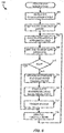
- routine 700 to calculate valve hysteresis, resolution and dead band based upon the exploitation of the difference between process control loop controller output and the feedback signal (e.g., back calculation signal) is shown.
- the routine initializes the calculation cycle, and set the calculation cycle time, T calc .
- the calculation cycle time, T calc may be approximately equal to 30 times the time to steady state, T ss , for a controlled process (i.e., T ca / c ⁇ 30 T ss ).
- the calculation cycle time, T ca / c may be approximately equal to 100 times the process control loop controller integral time, T i , (i.e., T calc ⁇ 100 T i ).
- valve direction is set to NONE for initialization.
- the functions of blocks 706, 708 and 710 are then performed for each model evaluation scan in the adaptive process control loop.
- the change in control loop controller output, OUT(t-i), and the change in the feedback signal, BKCAL_IN(t), where i is set to 1 as a default value (but is otherwise adjustable) are calculated according to equations 8 and 9 above.
- the valve direction is set based upon the difference between the controller loop controller output and the feedback signal. For example, the valve direction is set to UP if: OUT t ⁇ i ⁇ BKCAL _ IN t > 0 and the valve direction is set to DOWN if: OUT t ⁇ i ⁇ BKCAL _ IN t ⁇ 0 If neither equation 16 nor 17 is true, then the previous direction of the valve is retained.
- the rest of the calculations for the model evaluation scan are skipped if: ⁇ OUT t ⁇ i > ⁇ or ⁇ BKCAL _ IN t > ⁇ where ⁇ may be set to 3% as a default value.
- the rest of the calculations for the model evaluation scan may be skipped if the valve direction is set to NONE.
- the hysteresis and dead band calculations for the valve are updated.
- the valve direction is set to UP and if: ⁇ ⁇ OUT t ⁇ i ⁇ 0 then "hysteresis up", ⁇ h + , is calculated when the controller output, OUT, opens the valve (i.e., OUT > BKCAL_IN).
- valve direction is set to DOWN and if: ⁇ ⁇ OUT t ⁇ i ⁇ 0 then "hysteresis down", ⁇ h - , is calculated when the controller output, OUT, closes the valve (i.e., OUT ⁇ BKCAL_IN).
- T calc the hysteresis, h, dead band, b , and resolution, ⁇ .
- the status is updated (or set). For example, if the results are ZEROS and the previous results are non-zeros, the valve diagnostics status is set to UNCERTAIN. If resolution is negative, the valve diagnostic status is set to BAD, and if the resolution is not negative, the valve diagnostics status is set to GOOD. At block 718, the routine 100 resumes with a new calculation cycle.
- the valve diagnostics for actuators with no back calculation signal is based on the process model and the best suited model for the adaptive control loops or automatically tuned loops.
- the oscillation amplitude on the process controller input signal from the process variable PV, Ampl(PV) and the oscillation amplitude on the process control loop controller output OUT, Ampl(OUT) are defined, and the hysteresis is calculated according to equation 11.
- the oscillation shape defined by a shape factor is used for identifying oscillations caused by the valve.
- h h ⁇ ⁇ ⁇ Ampl Noise ⁇ Gain
- ⁇ 2 and Gain is the process control loop controller proportional gain.
- the coefficient is 2.
- the coefficient is ⁇ /2.
- oscillation amplitude is defined as a half of difference between signal maximum and minimum values over calculation cycle.
- factor ( Shape ) Scale ( shape ( OUT ) - shape ( PV ).
- factori -factor ( Shape ) .
- the shape factor, factor ( Shape ) is a difference between shape coefficient for the output oscillations and the shape coefficient for the process variable oscillations.
- the shape factor may be scaled to have a minimum value 0 and a maximum value of 1 - ⁇ . The maximum value occurs when there are saw tooth signals on the controller output, OUT, and nearly rectangular process variable, PV, pulses, indicating typical oscillations caused by the valve dead band and resolution with relatively small noise.
- the minimum, close to a zero value of the shape factor, is when PV and OUT signals have similar or close to random signal shapes, which may occur when resolution and dead band are comparable with the noise level.
- the calculation cycle period for model based diagnostics is approximately the same as for the diagnostics with back calculated valve position. Filtering or averaging may be used to achieve stable results. While this may slow down the diagnostics, the limitation may not be significant, because the diagnostic is performed continuously on-line.
- the valve resolution and dead band diagnostic calculation has been implemented in the adaptive PID function block, being part of an industrial DCS structure.
- the DCS allows easy and flexible simulations of linear and non-linear process dynamics.
- the valve model as in the appendix was used with the second order plus dead time controlled process. The model recreates valve steady state characteristics and dynamic response.
- the applied random noise was 0.25% for resolution up to 0.5%.
- the applied random noise for larger resolutions additionally was 0.5% and 1.00%.
- the diagnostic results were exact up to two decimal places for all cases, except of intermittent calculation cycles. The results were not affected by the noise.
- the applied random noise level was as in the previous tests.
- the diagnosed resolution and dead band accuracy were dependent on the adaptive process model.
- diagnosed valve hysterysis was not affected by the adapted model, but rather by the process noise and disturbances.
- a higher process model gain contributed to the smaller diagnosed valve resolution.
- a model quality index may indicate the quality of the adapted model for the process control loop, where the adapted model is defined during an adaptation cycle for the process control loop, an example of which was provided above.
- Model quality may be calculated in various ways. In one example, model quality is defined during model identification (e.g., during a model evaluation scan).
- a poor model quality indicates a loop condition problem which may include valve, measurement noise, tuning or an improper setup for the adaptation.
- Model validation may be performed by comparing a final model output with the real process variable, PV. The squared error per evaluation scan is an attribute for the process control loop block.
- SqError k TotalSqError NumberofSamples
- SqError k SqError k ⁇ 1 ⁇ R
- SqError k e max
- the squared error, SqError(k) is the error from a previous adaptation cycle of the process control loop, adaptive controller block attribute.
- E max is the maximum acceptable adapted model error.
- R is the ratio validating acceptance of the current adapted model.
- a heuristic value of approximately 10 is used for adaptive model with parameter interpolation.
- the error ratio of the best model and the closest to the best also indicates the quality of the model and may be considered in model validation.
- the validation is performed to prevent instability of the loop tuned with the newly adapted model.
- An adapted model is defined as "good”, “uncertain”, or "bad”. This status may then be used for process control loop tuning in the diagnostics.
- model quality in an adaptive process control loop may be evaluation based on factors such as the number of adaptations, average filter factor, and model main parameter (gain) average value and variability of the last number, n, adaptations of that parameter.
- the filter factor (FF) may be calculated for every adapted parameter.
- the criteria used for the filter factor calculation may include a ratio of the maximum residual error to the minimum residual error (RE) and a test to determine if the model with a middle value parameter value has the smallest residual error. If the ratio is small, it implies high noise level or a significant distance from the true model value. If the ratio, is high it indicates a small noise level and/or fast convergence of the model parameters. Satisfaction of the test criteria indicates that true model value lies between low and high range of the parameter and an interpolated parameter value should be close to the true value.
- the defined filter factor uses the errors ratio accounting automatically for noise level and excitation signal level. As noise level increases, or as excitation signal level decreases, the ratio of the modeling errors for various parameters decreases.
- the values of coefficients may be adjusted to satisfy requirements of particular implementations.
- Noise may be accounted for on various levels, including model validation and excitation level.
- Model validation accounts for noise by developing the noise-dependent filter factor, FF. With higher noise or smaller excitations, FF is smaller. The excitation level is tested versus the noise/disturbance level.
- level NOL max stdev , stdev _ cap where stdev and stdev_cap are PID controller parameters of total standard deviation and capability standard deviation.
- the triggering events for the adaptation may be verified as min Delta SP>5 ⁇ NOL, min Delta OUT>5 ⁇ NOL ⁇ gain(PID), and min PULSE ampl.>7 ⁇ NOL ⁇ gain(PID).
- An oscillation index may indicate the stability of the process control loop.
- the oscillation index is a priority indicator of the overall process control loop, the value of which may be used to alert an operator to promptly attend to an unstable process control loop.
- Detection and evaluation of oscillations in a process control loop can be performed in a variety of ways that are suitable to obtain the amplitude and period of the oscillations.
- the oscillation status is then defined according to no oscillations (e.g., "Good”), oscillation exceeded minimum acceptable amplitude (e.g., "Uncertain”), and oscillations exceeding maximum acceptable amplitude (e.g., "Bad").
- the main diagnostic routine 600 evaluates loop conditions based on the status of the process control loop components (e.g., process control loop performance, process control loop device, adapted model quality and process control loop stability), and performs a function as a result of the evaluation, such as initiating a corrective action or setting alarms.
- the process control loop components e.g., process control loop performance, process control loop device, adapted model quality and process control loop stability
- a function as a result of the evaluation such as initiating a corrective action or setting alarms.
- alarming status is set for oscillatory process control loops, as well as for excessively high estimated valve hysteresis and low resolution.
- An example of a corrective action within a process control loop includes accounting for the diagnosed conditions during model acceptance.
- Another example of a corrective action includes filtering data used for control and identification intended for improving the next model identification. If the adapted model is "bad”, the results of the model are rejected. If "uncertain”, the model is partially accepted. In other words, the parameters of the actual process control loop model are calculated as a weighted average of adapted and actually used models. The model quality index is used in the process variable filter calculation.
- Process variable filtering for control is adjusted automatically and asynchronously to the adaptive procedure.
- the filter value is set based on the model identification status and the current value of the process model dead time, time constant and noise level defined by the process control loop parameters (e.g., capability standard deviation and total standard deviation). Filter adjustments are made periodically, not faster than once over time-to-steady-state period, T ss .
- STDEV is the total standard deviation
- STDEV_CAP is the capability standard deviation
- the quality of the last adapted model, ⁇ is equal to 0 if the last model status is "good”, equal to 1 if last model status is "uncertain”, and equal to 2 if the last month status is "bad”.
- process variable filter is applied for both model identification and control, no model correction after the identification may be avoided. If the process variable filter for both the process variable, PV, and controller output, OUT, is used only for the identification, then both the process variable and process control loop controller output filters are the same and are selected by applying the procedures provided above. There is an assumption that model correction is not required, because both process input and output data are delayed on the same value.
- diagnostic system and method, and other elements may be implemented in software, they may also be implemented in hardware, firmware, etc., and may be implemented by any other processor.
- the elements described herein may be implemented in a standard multi-purpose CPU or on specifically designed hardware or firmware such as an application-specific integrated circuit (ASIC) or other hard-wired device as desired.
- ASIC application-specific integrated circuit
- the software routine may be stored in any computer readable memory such as on a magnetic disk, a laser disk, or other storage medium, in a RAM or ROM of a computer or processor, in any database, etc.
- this software may be delivered to a user or a process plant via any known or desired delivery method including, for example, on a computer readable disk or other transportable computer storage mechanism or over a communication channel such as a telephone line, the internet, wireless communication, etc. (which are viewed as being the same as or interchangeable with providing such software via a transportable storage medium).
Landscapes
- Engineering & Computer Science (AREA)
- Physics & Mathematics (AREA)
- General Physics & Mathematics (AREA)
- Automation & Control Theory (AREA)
- Quality & Reliability (AREA)
- Manufacturing & Machinery (AREA)
- General Engineering & Computer Science (AREA)
- Health & Medical Sciences (AREA)
- Artificial Intelligence (AREA)
- Computer Vision & Pattern Recognition (AREA)
- Evolutionary Computation (AREA)
- Medical Informatics (AREA)
- Software Systems (AREA)
- Feedback Control In General (AREA)
- Testing And Monitoring For Control Systems (AREA)
Claims (14)
- Verfahren zur Diagnose einer Prozesssteuerschleife, die eine Mehrzahl von Prozesssteuerschleifengeräten aufweist, wobei die Prozesssteuerschleife basierend auf adaptiven Prozessschleifenparametern gesteuert wird, die aus einem adaptierten Modell der Prozesssteuerschleife für jeden Parameter der Prozesssteuerschleife berechnet werden, wobei das Verfahren aufweist:Bewerten einer Performance der Prozesssteuerschleife;Bewerten eines Zustandes eines Prozesssteuerschleifengerätes innerhalb der Prozesssteuerschleife;Bewerten einer Qualität des adaptierten Modells der Prozesssteuerschleife;Bewerten einer Stabilität der Prozesssteuerschleife;Erzeugen einer Diagnoseindex aus jeder der Bewertungen;Bewerten eines Zustands der Prozesssteuerschleife aus dem einen Diagnoseindex oder den mehreren Diagnoseindizes; undautomatisches Einstellen eines Prozessvariablenfilters basierend auf der Bewertung des Zustandes der Prozesssteuerschleife aus dem einen Diagnoseindex oder den mehreren Diagnoseindizes.
- Verfahren nach Anspruch 1, wobei das Erzeugen eines Diagnoseindex aus jeder der Bewertungen aufweist das Erzeugen von einem von:einem Variabilitätsindex aus einer Bewertung der Performance der Prozesssteuerschleife;einer minimalen Standardabweichung aus der Bewertung der Performance der Prozesssteuerschleife;einem Unempfindlichkeitsbereich oder einer toten Zone eines Prozesssteuerschleifengerätes aus der Bewertung des Zustands des Prozesssteuerschleifengerätes innerhalb der Prozesssteuerschleife;einer Hysterese eines Prozesssteuerschleifengerätes aus der Bewertung des Zustandes des Prozesssteuerschleifengerätes innerhalb der Prozesssteuerschleife;einer Auflösung eines Prozesssteuerschleifengerätes aus der Bewertung des Zustandes des Prozesssteuerschleifengerätes innerhalb der Prozesssteuerschleife;einem adaptierten Modellqualitätsindex aus der Bewertung der Qualität des adaptierten Modells der Prozesssteuerschleife; odereinem Oszillationsindex aus der Bewertung der Stabilität der Prozesssteuerschleife.
- Verfahren nach Anspruch 2, wobei das Erzeugen des Variabilitätsindex aus der Bewertung der Performance der Prozesssteuerschleife das Berechnen des Variabilitätsindex aufweist als:
 Slq die minimale Standardabweichung,Stot die tatsächlich gemessene Standardabweichung,s ein Sensitivitätsfaktor sind.
 - Verfahren nach Anspruch 2, wobei das Erzeugen einer minimalen Standardabweichung aus der Bewertung der Performance der Prozesssteuerschleife das Berechnen der minimalen Standardabweichung aufweist als:

- Verfahren nach Anspruch 2, wobei das Erzeugen des Unempfindlichkeitsbereiches des Prozesssteuerschleifengerätes aus der Bewertung des Zustandes des Prozesssteuerschleifengerätes innerhalb der Prozesssteuerschleife das Berechnen des Unempfindlichkeitsbereiches des Prozesssteuerschleifengerätes aufweist als:


 OUT(t) ein Prozesssteuersignal an das Prozesssteuerschleifengerät ist,BKCAL_IN(t) ein Rückberechnungssignal vom Prozesssteuerschleifengerät ist,i eine Rückberechnungssignalverzögerung vom Prozesssteuerschleifengerät ist.
 - Verfahren nach Anspruch 5, wobei das Erzeugen des Unempfindlichkeitsbereiches des Prozesssteuerschleifengerätes aus der Bewertung des Zustandes des Prozesssteuerschleifengerätes innerhalb der Prozesssteuerschleife das Berechnen des Unempfindlichkeitsbereiches des Prozesssteuerschleifengerätes aufweist als:
 Ampl(OUT) die Oszillationsamplitude auf einem Prozesssteuersignalcontrollerausgang OUT, istAmpl(PV) die Oszillationsamplitude auf einem Prozesssteuerschleifencontrollereingangssignal von der Prozessvariablen, PV, istKp die Prozessgüte ist.
 - Verfahren nach Anspruch 2, wobei das Erzeugen der Hysterese eines Prozesssteuerschleifengerätes aus der Bewertung des Zustandes des Prozesssteuerschleifengerätes innerhalb der Prozesssteuerschleife das Berechnen der Hysterese des Prozesssteuerschleifengerätes aufweist als:
 b ein Unempfindlichkeitsbereich des Prozesssteuerschleifengerätes ist,δ eine Auflösung des Prozesssteuerschleifengerätes ist,i die Rückberechnungssignalverzögerung in Prozesssteuerschleifenmodulscans der adaptiven Prozesssteuerschleife ist,max Δ i ein Maximalwert eines Rückberechnungssignals ist.
 - Verfahren nach Anspruch 2, wobei das Erzeugen der Hysterese eines Prozesssteuerschleifengerätes aus der Bewertung des Zustandes des Prozesssteuerschleifengerätes innerhalb der Prozesssteuerschleife das Berechnen der Hysterese des Prozesssteuerschleifengerätes aufweist als:

- Verfahren nach Anspruch 2, wobei das Erzeugen der Auflösung eines Prozesssteuerschleifengerätes aus der Bewertung des Zustandes des Prozesssteuerschleifengerätes innerhalb der Prozesssteuerschleife das Berechnen der Auflösung des Prozesssteuerschleifengerätes aufweist als:
 b ein Unempfindlichkeitsbereich des Prozesssteuerschleifengerätes ist,h eine Hysterese des Prozesssteuerschleifengerätes ist; oderwobei das Erzeugen der Auflösung eines Prozesssteuerschleifengerätes aus der Bewertung des Zustandes des Prozesssteuerschleifengerätes innerhalb der Prozesssteuerschleife das Berechnen der Auflösung des Prozesssteuerschleifengerätes aufweist als:
 Ampl(PV) die Oszillationsamplitude auf dem Prozesssteuereingangssignal ist,Kp die Prozessgüte ist.
 - Verfahren nach Anspruch 2, wobei das Erzeugen der Auflösung eines Prozesssteuerschleifengerätes aus der Bewertung des Zustandes des Prozesssteuerschleifengerätes innerhalb der Prozesssteuerschleife das Berechnen der Auflösung des Prozesssteuerschleifengerätes aufweist aus einer Abschätzung einer Oszillationsperiode der Prozesssteuerschleife aufweist, wobei die Abschätzung ausgedrückt wird als:
 A und B heuristische Parameterwerte sind, die für einen selbstregelnden Prozess abgeschätzt sind,A größer als B ist,Ti eine Controllerrücksetzzeit ist,Kc eine Controllergüte ist.
 - Verfahren nach Anspruch 2, wobei das Erzeugen des adaptierten Modellqualitätsindex aus der Bewertung der Qualität des adaptierten Modells der Prozesssteuerschleife das Berechnen eines Fehlerquadrats des adaptierten Modells aufweist als:


 SqError(k) der Fehler aus einem vorangehenden Adaptionszyklus der Prozesssteuerschleife ist,Emax der maximal-akzeptable adaptierte Modellfehler ist,R das Verhältnis des Validierens der Akzeptanz des aktuell adaptierten Modells ist.
 - Verfahren nach Anspruch 2, weiter aufweisend das Setzen eines Alarms basierend auf der Bewertung des Zustandes der Prozesssteuerschleife aus dem einen Diagnoseindex oder den mehreren Diagnoseindizes.
- Verfahren nach Anspruch 2, weiter aufweisend das automatische Einstellen eines adaptierten Modells der adaptiven Prozesssteuerschleife basierend auf der Bewertung des Zustandes der Prozesssteuerschleife aus dem einen Diagnoseindex oder den mehreren Diagnoseindizes.
- Verfahren nach Anspruch 1, wobei das automatische Einstellen des Prozessvariablenfilters das Berechnen einer Prozessvariablenfilter-Zeitkonstante aufweist als:
 Td eine Totzeit das adaptierten Modells ist,T eine Zeitkonstante des adaptierten Modells ist,φ eine Qualität des letzten adaptierten Modells ist,STDEV eine Gesamt-Standardabweichung der Prozesssteuerschleife ist,STDEV_CAP eine Fähigkeits-Standardabweichung der Prozesssteuerschleife ist,wobei das automatische Einstellen des Prozessvariablenfilters bevorzugt das Anwenden von effektiven Prozessvariablenfilterwerten aufweist als:
Applications Claiming Priority (4)
| Application Number | Priority Date | Filing Date | Title |
|---|---|---|---|
| US74232005P | 2005-12-05 | 2005-12-05 | |
| US11/565,767 US8509926B2 (en) | 2005-12-05 | 2006-12-01 | Self-diagnostic process control loop for a process plant |
| EP06839107A EP1963939A2 (de) | 2005-12-05 | 2006-12-05 | Selbstdiagnose- prozessregelkreis für eine prozessanlage |
| PCT/US2006/046589 WO2007067644A2 (en) | 2005-12-05 | 2006-12-05 | Self-diagnostic process control loop for a process plant |
Related Parent Applications (1)
| Application Number | Title | Priority Date | Filing Date |
|---|---|---|---|
| EP06839107A Division EP1963939A2 (de) | 2005-12-05 | 2006-12-05 | Selbstdiagnose- prozessregelkreis für eine prozessanlage |
Publications (3)
| Publication Number | Publication Date |
|---|---|
| EP2889712A2 EP2889712A2 (de) | 2015-07-01 |
| EP2889712A3 EP2889712A3 (de) | 2015-07-15 |
| EP2889712B1 true EP2889712B1 (de) | 2020-02-05 |
Family
ID=38068747
Family Applications (2)
| Application Number | Title | Priority Date | Filing Date |
|---|---|---|---|
| EP15152084.8A Active EP2889712B1 (de) | 2005-12-05 | 2006-12-05 | Selbstprüfungsprozessregelschleife für eine prozessanlage |
| EP06839107A Withdrawn EP1963939A2 (de) | 2005-12-05 | 2006-12-05 | Selbstdiagnose- prozessregelkreis für eine prozessanlage |
Family Applications After (1)
| Application Number | Title | Priority Date | Filing Date |
|---|---|---|---|
| EP06839107A Withdrawn EP1963939A2 (de) | 2005-12-05 | 2006-12-05 | Selbstdiagnose- prozessregelkreis für eine prozessanlage |
Country Status (6)
| Country | Link |
|---|---|
| US (2) | US8509926B2 (de) |
| EP (2) | EP2889712B1 (de) |
| JP (1) | JP5096358B2 (de) |
| CN (2) | CN103353753B (de) |
| GB (1) | GB2446344B (de) |
| WO (1) | WO2007067644A2 (de) |
Families Citing this family (45)
| Publication number | Priority date | Publication date | Assignee | Title |
|---|---|---|---|---|
| US8504341B2 (en) * | 2006-01-31 | 2013-08-06 | Landmark Graphics Corporation | Methods, systems, and computer readable media for fast updating of oil and gas field production models with physical and proxy simulators |
| CN101379271B (zh) * | 2006-01-31 | 2012-11-07 | 兰德马克绘图公司 | 使用代理仿真器的用于实时油气田生产优化的方法、系统和计算机可读介质 |
| US8756039B2 (en) * | 2010-03-02 | 2014-06-17 | Fisher-Rosemount Systems, Inc. | Rapid process model identification and generation |
| US20120041744A1 (en) * | 2010-07-28 | 2012-02-16 | Kantzes Christopher P | Handheld field maintenance tool with field device simulation capability |
| US9217565B2 (en) | 2010-08-16 | 2015-12-22 | Emerson Process Management Power & Water Solutions, Inc. | Dynamic matrix control of steam temperature with prevention of saturated steam entry into superheater |
| US9335042B2 (en) | 2010-08-16 | 2016-05-10 | Emerson Process Management Power & Water Solutions, Inc. | Steam temperature control using dynamic matrix control |
| US9447963B2 (en) | 2010-08-16 | 2016-09-20 | Emerson Process Management Power & Water Solutions, Inc. | Dynamic tuning of dynamic matrix control of steam temperature |
| TWI515522B (zh) * | 2010-12-28 | 2016-01-01 | 萬國商業機器公司 | 測定系統情況的方法、電腦程式及電腦 |
| US9163828B2 (en) | 2011-10-31 | 2015-10-20 | Emerson Process Management Power & Water Solutions, Inc. | Model-based load demand control |
| WO2014015096A2 (en) | 2012-07-19 | 2014-01-23 | Saudi Arabian Oil Company | System and method for effective plant performance monitoring in gas oil separation plant (gosp) |
| US9146554B2 (en) * | 2012-10-16 | 2015-09-29 | Adam Hoban | Aggregate processing control system |
| CN104079425B (zh) * | 2013-03-31 | 2017-09-15 | 上海贝尔股份有限公司 | 一种用于匹配设备的方法、装置和系统 |
| US9851707B2 (en) | 2013-09-04 | 2017-12-26 | Fisher-Rosemount Systems, Inc. | Bulk field device operations |
| US10459418B2 (en) | 2013-09-04 | 2019-10-29 | Fisher-Rosemount Systems, Inc. | Technology for assessing and presenting field device commissioning information associated with a process plant |
| US9983574B2 (en) | 2013-09-30 | 2018-05-29 | United States Gypsum Company | Systems and methods for controlling a conveyor system during product changeovers |
| US9733641B2 (en) * | 2013-10-22 | 2017-08-15 | Yokogawa Electric Corporation | Method and apparatus for performing diagnostics on a conventional control valve |
| US9777937B2 (en) * | 2014-04-22 | 2017-10-03 | Honeywell International Inc. | Controller and loop performance monitoring in a heating, ventilating, and air conditioning system |
| CN104088842B (zh) * | 2014-06-30 | 2016-05-11 | 武汉船用机械有限责任公司 | 一种比例方向阀控制死区的自动识别及补偿方法和系统 |
| EP2988186B1 (de) * | 2014-08-22 | 2018-03-14 | Siemens Aktiengesellschaft | Nachweis von konsistentem stationärem Verhalten in verfahrenstechnischen Anlagen |
| CN106796416B (zh) * | 2014-10-09 | 2019-11-05 | 三菱电机株式会社 | 控制装置以及控制方法 |
| CN105988437A (zh) * | 2015-02-10 | 2016-10-05 | 张家港市宏鑫源科技有限公司 | 一种采用分布式控制系统的多级万能轧机 |
| EP3056957B1 (de) * | 2015-02-16 | 2019-03-27 | Siemens Aktiengesellschaft | Diagnoseeinrichtung und -verfahren zur Überwachung des Betriebs eines Regelkreises |
| EP3065015B1 (de) * | 2015-03-04 | 2018-09-26 | Siemens Aktiengesellschaft | Diagnoseeinrichtung und -verfahren zur überwachung des betriebs von regelkreisen |
| US20160349726A1 (en) * | 2015-05-27 | 2016-12-01 | Honeywell International, Inc. | Apparatus and method for variable data collection of intelligent loop performance monitoring system in bandwidth-constrained dcs |
| CN105005296B (zh) * | 2015-07-27 | 2018-07-24 | 浙江大学 | 一种基于相位斜率指标的控制过程非线性振荡回路定位方法 |
| US10371285B2 (en) * | 2015-10-27 | 2019-08-06 | Dresser, Llc | Predicting maintenance requirements for a valve assembly |
| GB2556315A (en) * | 2016-03-23 | 2018-05-30 | Univ Coventry | Control system |
| US10678224B2 (en) * | 2017-06-21 | 2020-06-09 | Fisher-Rosemount Systems, Inc. | Loop interface |
| US11150635B2 (en) | 2017-10-02 | 2021-10-19 | Fisher-Rosemount Systems, Inc. | Projects within a process control asset management system |
| JP6923484B2 (ja) * | 2018-05-15 | 2021-08-18 | ファナック株式会社 | 加工条件調整装置及び機械学習装置 |
| US11714394B2 (en) | 2018-09-28 | 2023-08-01 | Fisher-Rosemount Systems, Inc | Bulk commissioning of field devices within a process plant |
| TWI686615B (zh) * | 2018-10-22 | 2020-03-01 | 財團法人工業技術研究院 | 擾動源定位方法 |
| GB2623651B (en) | 2019-06-10 | 2024-11-20 | Fisher Rosemount Systems Inc | Automatic load balancing and performance leveling of virtual nodes running real-time control in process control systems |
| GB2621485B (en) | 2019-06-10 | 2024-08-28 | Fisher Rosemount Systems Inc | Ease of node switchovers in process control systems |
| US11249464B2 (en) | 2019-06-10 | 2022-02-15 | Fisher-Rosemount Systems, Inc. | Industrial control system architecture for real-time simulation and process control |
| GB2589661B (en) | 2019-06-10 | 2024-06-05 | Fisher Rosemount Systems Inc | Virtualized real-time I/O in process control systems |
| US11231701B2 (en) * | 2019-06-10 | 2022-01-25 | Fisher-Rosemount Systems, Inc. | Publish/subscribe protocol for real-time process control |
| US11550311B2 (en) | 2019-06-10 | 2023-01-10 | Fisher-Rosemount Systems, Inc. | Centralized virtualization management node in process control systems |
| US11467543B2 (en) * | 2019-09-20 | 2022-10-11 | Fisher-Rosemount Systems, Inc. | Process controller design with process approximation and lambda tuning |
| DE102020118556A1 (de) * | 2020-07-14 | 2022-03-10 | Samson Aktiengesellschaft | Ventilstellgerät, prozesstechnische Anlage mit Ventilstellgerät, Diagnoseverfahren und Verwendung eines Ventilstellgeräts |
| US11656149B2 (en) * | 2020-07-17 | 2023-05-23 | Fisher Controls International Llc | Methods and apparatus to automatically determine friction of a control valve |
| DE102020126355A1 (de) * | 2020-10-08 | 2022-04-14 | Krones Aktiengesellschaft | Verfahren zum Betreiben einer Maschine in einer Verarbeitungsanlage für Behälter und Maschine zur Behandlung von Behältern |
| CN113656461B (zh) * | 2021-08-17 | 2024-03-19 | 北京百度网讯科技有限公司 | 数据处理方法、装置、电子设备和介质 |
| CN113960922B (zh) * | 2021-12-23 | 2022-03-11 | 深圳市晨北科技有限公司 | Pid控制参数整定方法、装置、设备及存储介质 |
| DE102023117268B4 (de) | 2023-06-29 | 2025-05-22 | Samson Aktiengesellschaft | Verfahren, System und Vorrichtungen zum Erkennen der Ursache von Schwingungen in einem Regelkreis eines Regelventils in einer geregelten prozesstechnischen Anlage |
Family Cites Families (53)
| Publication number | Priority date | Publication date | Assignee | Title |
|---|---|---|---|---|
| JPS6069702A (ja) | 1983-09-26 | 1985-04-20 | Toshiba Corp | サンプル値プロセス制御装置 |
| US5018218A (en) * | 1988-08-29 | 1991-05-21 | Raytheon Company | Confirmed boundary pattern matching |
| JP2553675B2 (ja) | 1988-11-18 | 1996-11-13 | 日本電気硝子株式会社 | プロセスの制御方法 |
| US5018215A (en) | 1990-03-23 | 1991-05-21 | Honeywell Inc. | Knowledge and model based adaptive signal processor |
| US5394322A (en) * | 1990-07-16 | 1995-02-28 | The Foxboro Company | Self-tuning controller that extracts process model characteristics |
| US5406474A (en) * | 1990-07-16 | 1995-04-11 | The Foxboro Company | Self-tuning controller |
| US5180896A (en) | 1990-10-11 | 1993-01-19 | University Of Florida | System and method for in-line heating of medical fluid |
| US5159547A (en) | 1990-10-16 | 1992-10-27 | Rockwell International Corporation | Self-monitoring tuner for feedback controller |
| US5335164A (en) | 1991-07-31 | 1994-08-02 | Universal Dynamics Limited | Method and apparatus for adaptive control |
| US5283729A (en) | 1991-08-30 | 1994-02-01 | Fisher-Rosemount Systems, Inc. | Tuning arrangement for turning the control parameters of a controller |
| CA2118598C (en) | 1991-12-18 | 2004-04-13 | Anoop K. Mathur | A closed loop neural network automatic tuner |
| US5453925A (en) | 1993-05-28 | 1995-09-26 | Fisher Controls International, Inc. | System and method for automatically tuning a process controller |
| US6041320A (en) | 1993-08-23 | 2000-03-21 | Fisher Controls International, Inc. | Multi-region fuzzy logic control system with auxiliary variables |
| US5461559A (en) | 1993-10-04 | 1995-10-24 | The United States Of America As Represented By The Secretary Of The Air Force | Hierarchical control system for molecular beam epitaxy |
| US5587899A (en) | 1994-06-10 | 1996-12-24 | Fisher-Rosemount Systems, Inc. | Method and apparatus for determining the ultimate gain and ultimate period of a controlled process |
| US5568378A (en) | 1994-10-24 | 1996-10-22 | Fisher-Rosemount Systems, Inc. | Variable horizon predictor for controlling dead time dominant processes, multivariable interactive processes, and processes with time variant dynamics |
| US5748467A (en) | 1995-02-21 | 1998-05-05 | Fisher-Rosemont Systems, Inc. | Method of adapting and applying control parameters in non-linear process controllers |
| US6092919A (en) * | 1995-08-01 | 2000-07-25 | Guided Systems Technologies, Inc. | System and method for adaptive control of uncertain nonlinear processes |
| US6249712B1 (en) | 1995-09-26 | 2001-06-19 | William J. N-O. Boiquaye | Adaptive control process and system |
| US5966679A (en) | 1995-10-30 | 1999-10-12 | Fisher Controls International, Inc. | Method of and apparatus for nonobtrusively obtaining on-line measurements of a process control device parameter |
| US5992229A (en) * | 1996-02-05 | 1999-11-30 | Neles-Jamesbury Oy | Method and equipment for determining the performance of control valve |
| JP3412384B2 (ja) | 1996-03-13 | 2003-06-03 | 株式会社日立製作所 | 制御モデル構築支援装置 |
| US7085610B2 (en) * | 1996-03-28 | 2006-08-01 | Fisher-Rosemount Systems, Inc. | Root cause diagnostics |
| GB9608953D0 (en) * | 1996-04-29 | 1996-07-03 | Pulp Paper Res Inst | Automatic control loop monitoring and diagnostics |
| US5970430A (en) * | 1996-10-04 | 1999-10-19 | Fisher Controls International, Inc. | Local device and process diagnostics in a process control network having distributed control functions |
| IT1295107B1 (it) | 1997-04-29 | 1999-04-30 | Piegatrici Macch Elettr | Sistema di piegatura perfezionato per macchine piegatrici |
| US6035878A (en) | 1997-09-22 | 2000-03-14 | Fisher Controls International, Inc. | Diagnostic device and method for pressure regulator |
| US6466893B1 (en) * | 1997-09-29 | 2002-10-15 | Fisher Controls International, Inc. | Statistical determination of estimates of process control loop parameters |
| US6192321B1 (en) | 1997-09-29 | 2001-02-20 | Fisher Controls International, Inc. | Method of and apparatus for deterministically obtaining measurements |
| US6804618B2 (en) * | 1997-09-29 | 2004-10-12 | Fisher Controls International, Llc | Detection and discrimination of instabilities in process control loops |
| AU5478899A (en) * | 1998-08-21 | 2000-03-14 | Micro Motion, Inc. | Resistance based process control device diagnostics |
| WO2000033209A2 (de) | 1998-12-03 | 2000-06-08 | Siemens Aktiengesellschaft | Verfahren und anordnung zum entwurf eines technischen systems |
| US6298454B1 (en) * | 1999-02-22 | 2001-10-02 | Fisher-Rosemount Systems, Inc. | Diagnostics in a process control system |
| US7206646B2 (en) * | 1999-02-22 | 2007-04-17 | Fisher-Rosemount Systems, Inc. | Method and apparatus for performing a function in a plant using process performance monitoring with process equipment monitoring and control |
| GB2347233B (en) | 1999-02-22 | 2003-09-10 | Fisher Rosemount Systems Inc | Diagnostics in a process control system which uses multi-variable control techniques |
| US20020068857A1 (en) * | 2000-02-14 | 2002-06-06 | Iliff Edwin C. | Automated diagnostic system and method including reuse of diagnostic objects |
| US6826521B1 (en) * | 2000-04-06 | 2004-11-30 | Abb Automation Inc. | System and methodology and adaptive, linear model predictive control based on rigorous, nonlinear process model |
| US6577908B1 (en) | 2000-06-20 | 2003-06-10 | Fisher Rosemount Systems, Inc | Adaptive feedback/feedforward PID controller |
| JP3965668B2 (ja) * | 2000-08-30 | 2007-08-29 | 横河電機株式会社 | 適応制御方法およびその装置 |
| US7720727B2 (en) * | 2001-03-01 | 2010-05-18 | Fisher-Rosemount Systems, Inc. | Economic calculations in process control system |
| US6795798B2 (en) * | 2001-03-01 | 2004-09-21 | Fisher-Rosemount Systems, Inc. | Remote analysis of process control plant data |
| US6813532B2 (en) * | 2001-03-01 | 2004-11-02 | Fisher-Rosemount Systems, Inc. | Creation and display of indices within a process plant |
| US6594589B1 (en) | 2001-05-23 | 2003-07-15 | Advanced Micro Devices, Inc. | Method and apparatus for monitoring tool health |
| FI20011742L (fi) * | 2001-08-31 | 2003-03-01 | Metso Field Systems Oy | Menetelmä ja järjestelmä teollisuusprosessin säätöpiirin suorituskyvun analysoimiseksi |
| FI114947B (fi) | 2002-09-13 | 2005-01-31 | Metso Automation Oy | Menetelmä ja laitteisto prosessissa olevan prosessilaitteen hystereesin määrittämiseksi |
| JP2004126688A (ja) * | 2002-09-30 | 2004-04-22 | Yokogawa Electric Corp | オフライン診断システム |
| JP4166637B2 (ja) * | 2003-07-10 | 2008-10-15 | 株式会社東芝 | プロセス制御装置の調整方法及びその調整ツール |
| US7627441B2 (en) | 2003-09-30 | 2009-12-01 | Rosemount Inc. | Process device with vibration based diagnostics |
| US7676287B2 (en) * | 2004-03-03 | 2010-03-09 | Fisher-Rosemount Systems, Inc. | Configuration system and method for abnormal situation prevention in a process plant |
| US7024336B2 (en) * | 2004-05-13 | 2006-04-04 | Johnson Controls Technology Company | Method of and apparatus for evaluating the performance of a control system |
| US7529644B2 (en) * | 2004-08-31 | 2009-05-05 | Watlow Electric Manufacturing Company | Method of diagnosing an operations systems |
| US7444191B2 (en) | 2005-10-04 | 2008-10-28 | Fisher-Rosemount Systems, Inc. | Process model identification in a process control system |
| SE530380C2 (sv) | 2006-10-03 | 2008-05-20 | Abb Ab | Automatisk uppskattning av glapp |
-
2006
- 2006-12-01 US US11/565,767 patent/US8509926B2/en active Active
- 2006-12-05 WO PCT/US2006/046589 patent/WO2007067644A2/en not_active Ceased
- 2006-12-05 EP EP15152084.8A patent/EP2889712B1/de active Active
- 2006-12-05 CN CN201310252901.5A patent/CN103353753B/zh active Active
- 2006-12-05 GB GB0810146A patent/GB2446344B/en not_active Expired - Fee Related
- 2006-12-05 CN CN200680045686XA patent/CN101322086B/zh not_active Expired - Fee Related
- 2006-12-05 EP EP06839107A patent/EP1963939A2/de not_active Withdrawn
- 2006-12-05 JP JP2008544487A patent/JP5096358B2/ja active Active
-
2012
- 2012-10-18 US US13/655,044 patent/US8909360B2/en active Active
Non-Patent Citations (1)
| Title |
|---|
| None * |
Also Published As
| Publication number | Publication date |
|---|---|
| US20070150079A1 (en) | 2007-06-28 |
| JP2009518749A (ja) | 2009-05-07 |
| JP5096358B2 (ja) | 2012-12-12 |
| EP2889712A3 (de) | 2015-07-15 |
| CN101322086A (zh) | 2008-12-10 |
| GB2446344A (en) | 2008-08-06 |
| CN103353753B (zh) | 2016-03-09 |
| GB0810146D0 (en) | 2008-07-09 |
| EP2889712A2 (de) | 2015-07-01 |
| CN103353753A (zh) | 2013-10-16 |
| CN101322086B (zh) | 2013-07-24 |
| WO2007067644A2 (en) | 2007-06-14 |
| EP1963939A2 (de) | 2008-09-03 |
| GB2446344B (en) | 2011-08-10 |
| US20130046396A1 (en) | 2013-02-21 |
| US8909360B2 (en) | 2014-12-09 |
| WO2007067644A3 (en) | 2007-08-09 |
| US8509926B2 (en) | 2013-08-13 |
| HK1124132A1 (en) | 2009-07-03 |
Similar Documents
| Publication | Publication Date | Title |
|---|---|---|
| EP2889712B1 (de) | Selbstprüfungsprozessregelschleife für eine prozessanlage | |
| US7912676B2 (en) | Method and system for detecting abnormal operation in a process plant | |
| US7966149B2 (en) | Multivariate detection of transient regions in a process control system | |
| EP1728132B1 (de) | Datendarstellungssystem zur verhinderung von anomalen situationen in einer verarbeitungsanlage | |
| US8712731B2 (en) | Simplified algorithm for abnormal situation prevention in load following applications including plugged line diagnostics in a dynamic process | |
| EP1728133B1 (de) | Verhinderung anormaler situationen in einer betriebsanlage | |
| US8055358B2 (en) | Multi-objective predictive process optimization with concurrent process simulation | |
| EP1725919B1 (de) | Konfigurationssystem und -verfahren zur verhinderung anomaler situationen in einer betriebsanlage | |
| US8032340B2 (en) | Method and system for modeling a process variable in a process plant | |
| US20090093892A1 (en) | Automatic determination of the order of a polynomial regression model applied to abnormal situation prevention in a process plant | |
| US7930136B2 (en) | Simplified algorithm for abnormal situation prevention in load following applications | |
| WO2008085705A1 (en) | Method and system for modeling a process in a process plant | |
| US8606544B2 (en) | Methods and systems for detecting deviation of a process variable from expected values | |
| WO2008014344A2 (en) | Model based method for detecting abnormal operation of a level regulatory control loop and associated apparatus | |
| US20090093893A1 (en) | System and method for recognizing and compensating for invalid regression model applied to abnormal situation prevention | |
| Muhammad | Detection and compensation of valve stiction in control loops |
Legal Events
| Date | Code | Title | Description |
|---|---|---|---|
| PUAL | Search report despatched |
Free format text: ORIGINAL CODE: 0009013 |
|
| PUAI | Public reference made under article 153(3) epc to a published international application that has entered the european phase |
Free format text: ORIGINAL CODE: 0009012 |
|
| 17P | Request for examination filed |
Effective date: 20150122 |
|
| AC | Divisional application: reference to earlier application |
Ref document number: 1963939 Country of ref document: EP Kind code of ref document: P |
|
| AK | Designated contracting states |
Kind code of ref document: A2 Designated state(s): AT BE BG CH CY CZ DE DK EE ES FI FR GB GR HU IE IS IT LI LT LU LV MC NL PL PT RO SE SI SK TR |
|
| AK | Designated contracting states |
Kind code of ref document: A3 Designated state(s): AT BE BG CH CY CZ DE DK EE ES FI FR GB GR HU IE IS IT LI LT LU LV MC NL PL PT RO SE SI SK TR |
|
| RIC1 | Information provided on ipc code assigned before grant |
Ipc: G05B 23/02 20060101AFI20150605BHEP |
|
| R17P | Request for examination filed (corrected) |
Effective date: 20160112 |
|
| RBV | Designated contracting states (corrected) |
Designated state(s): AT BE BG CH CY CZ DE DK EE ES FI FR GB GR HU IE IS IT LI LT LU LV MC NL PL PT RO SE SI SK TR |
|
| GRAP | Despatch of communication of intention to grant a patent |
Free format text: ORIGINAL CODE: EPIDOSNIGR1 |
|
| STAA | Information on the status of an ep patent application or granted ep patent |
Free format text: STATUS: GRANT OF PATENT IS INTENDED |
|
| INTG | Intention to grant announced |
Effective date: 20190702 |
|
| GRAS | Grant fee paid |
Free format text: ORIGINAL CODE: EPIDOSNIGR3 |
|
| GRAA | (expected) grant |
Free format text: ORIGINAL CODE: 0009210 |
|
| STAA | Information on the status of an ep patent application or granted ep patent |
Free format text: STATUS: THE PATENT HAS BEEN GRANTED |
|
| AC | Divisional application: reference to earlier application |
Ref document number: 1963939 Country of ref document: EP Kind code of ref document: P |
|
| AK | Designated contracting states |
Kind code of ref document: B1 Designated state(s): AT BE BG CH CY CZ DE DK EE ES FI FR GB GR HU IE IS IT LI LT LU LV MC NL PL PT RO SE SI SK TR |
|
| REG | Reference to a national code |
Ref country code: GB Ref legal event code: FG4D |
|
| REG | Reference to a national code |
Ref country code: AT Ref legal event code: REF Ref document number: 1230348 Country of ref document: AT Kind code of ref document: T Effective date: 20200215 |
|
| REG | Reference to a national code |
Ref country code: DE Ref legal event code: R096 Ref document number: 602006059107 Country of ref document: DE |
|
| REG | Reference to a national code |
Ref country code: IE Ref legal event code: FG4D |
|
| REG | Reference to a national code |
Ref country code: CH Ref legal event code: EP |
|
| REG | Reference to a national code |
Ref country code: NL Ref legal event code: MP Effective date: 20200205 |
|
| PG25 | Lapsed in a contracting state [announced via postgrant information from national office to epo] |
Ref country code: PT Free format text: LAPSE BECAUSE OF FAILURE TO SUBMIT A TRANSLATION OF THE DESCRIPTION OR TO PAY THE FEE WITHIN THE PRESCRIBED TIME-LIMIT Effective date: 20200628 Ref country code: FI Free format text: LAPSE BECAUSE OF FAILURE TO SUBMIT A TRANSLATION OF THE DESCRIPTION OR TO PAY THE FEE WITHIN THE PRESCRIBED TIME-LIMIT Effective date: 20200205 |
|
| REG | Reference to a national code |
Ref country code: LT Ref legal event code: MG4D |
|
| PG25 | Lapsed in a contracting state [announced via postgrant information from national office to epo] |
Ref country code: IS Free format text: LAPSE BECAUSE OF FAILURE TO SUBMIT A TRANSLATION OF THE DESCRIPTION OR TO PAY THE FEE WITHIN THE PRESCRIBED TIME-LIMIT Effective date: 20200605 Ref country code: GR Free format text: LAPSE BECAUSE OF FAILURE TO SUBMIT A TRANSLATION OF THE DESCRIPTION OR TO PAY THE FEE WITHIN THE PRESCRIBED TIME-LIMIT Effective date: 20200506 Ref country code: BG Free format text: LAPSE BECAUSE OF FAILURE TO SUBMIT A TRANSLATION OF THE DESCRIPTION OR TO PAY THE FEE WITHIN THE PRESCRIBED TIME-LIMIT Effective date: 20200505 Ref country code: SE Free format text: LAPSE BECAUSE OF FAILURE TO SUBMIT A TRANSLATION OF THE DESCRIPTION OR TO PAY THE FEE WITHIN THE PRESCRIBED TIME-LIMIT Effective date: 20200205 Ref country code: LV Free format text: LAPSE BECAUSE OF FAILURE TO SUBMIT A TRANSLATION OF THE DESCRIPTION OR TO PAY THE FEE WITHIN THE PRESCRIBED TIME-LIMIT Effective date: 20200205 |
|
| PG25 | Lapsed in a contracting state [announced via postgrant information from national office to epo] |
Ref country code: NL Free format text: LAPSE BECAUSE OF FAILURE TO SUBMIT A TRANSLATION OF THE DESCRIPTION OR TO PAY THE FEE WITHIN THE PRESCRIBED TIME-LIMIT Effective date: 20200205 |
|
| PG25 | Lapsed in a contracting state [announced via postgrant information from national office to epo] |
Ref country code: CZ Free format text: LAPSE BECAUSE OF FAILURE TO SUBMIT A TRANSLATION OF THE DESCRIPTION OR TO PAY THE FEE WITHIN THE PRESCRIBED TIME-LIMIT Effective date: 20200205 Ref country code: LT Free format text: LAPSE BECAUSE OF FAILURE TO SUBMIT A TRANSLATION OF THE DESCRIPTION OR TO PAY THE FEE WITHIN THE PRESCRIBED TIME-LIMIT Effective date: 20200205 Ref country code: ES Free format text: LAPSE BECAUSE OF FAILURE TO SUBMIT A TRANSLATION OF THE DESCRIPTION OR TO PAY THE FEE WITHIN THE PRESCRIBED TIME-LIMIT Effective date: 20200205 Ref country code: DK Free format text: LAPSE BECAUSE OF FAILURE TO SUBMIT A TRANSLATION OF THE DESCRIPTION OR TO PAY THE FEE WITHIN THE PRESCRIBED TIME-LIMIT Effective date: 20200205 Ref country code: EE Free format text: LAPSE BECAUSE OF FAILURE TO SUBMIT A TRANSLATION OF THE DESCRIPTION OR TO PAY THE FEE WITHIN THE PRESCRIBED TIME-LIMIT Effective date: 20200205 Ref country code: SK Free format text: LAPSE BECAUSE OF FAILURE TO SUBMIT A TRANSLATION OF THE DESCRIPTION OR TO PAY THE FEE WITHIN THE PRESCRIBED TIME-LIMIT Effective date: 20200205 Ref country code: RO Free format text: LAPSE BECAUSE OF FAILURE TO SUBMIT A TRANSLATION OF THE DESCRIPTION OR TO PAY THE FEE WITHIN THE PRESCRIBED TIME-LIMIT Effective date: 20200205 |
|
| REG | Reference to a national code |
Ref country code: DE Ref legal event code: R097 Ref document number: 602006059107 Country of ref document: DE |
|
| REG | Reference to a national code |
Ref country code: AT Ref legal event code: MK05 Ref document number: 1230348 Country of ref document: AT Kind code of ref document: T Effective date: 20200205 |
|
| PLBE | No opposition filed within time limit |
Free format text: ORIGINAL CODE: 0009261 |
|
| STAA | Information on the status of an ep patent application or granted ep patent |
Free format text: STATUS: NO OPPOSITION FILED WITHIN TIME LIMIT |
|
| 26N | No opposition filed |
Effective date: 20201106 |
|
| PG25 | Lapsed in a contracting state [announced via postgrant information from national office to epo] |
Ref country code: AT Free format text: LAPSE BECAUSE OF FAILURE TO SUBMIT A TRANSLATION OF THE DESCRIPTION OR TO PAY THE FEE WITHIN THE PRESCRIBED TIME-LIMIT Effective date: 20200205 Ref country code: IT Free format text: LAPSE BECAUSE OF FAILURE TO SUBMIT A TRANSLATION OF THE DESCRIPTION OR TO PAY THE FEE WITHIN THE PRESCRIBED TIME-LIMIT Effective date: 20200205 |
|
| PG25 | Lapsed in a contracting state [announced via postgrant information from national office to epo] |
Ref country code: PL Free format text: LAPSE BECAUSE OF FAILURE TO SUBMIT A TRANSLATION OF THE DESCRIPTION OR TO PAY THE FEE WITHIN THE PRESCRIBED TIME-LIMIT Effective date: 20200205 Ref country code: SI Free format text: LAPSE BECAUSE OF FAILURE TO SUBMIT A TRANSLATION OF THE DESCRIPTION OR TO PAY THE FEE WITHIN THE PRESCRIBED TIME-LIMIT Effective date: 20200205 |
|
| REG | Reference to a national code |
Ref country code: CH Ref legal event code: PL |
|
| PG25 | Lapsed in a contracting state [announced via postgrant information from national office to epo] |
Ref country code: MC Free format text: LAPSE BECAUSE OF FAILURE TO SUBMIT A TRANSLATION OF THE DESCRIPTION OR TO PAY THE FEE WITHIN THE PRESCRIBED TIME-LIMIT Effective date: 20200205 |
|
| REG | Reference to a national code |
Ref country code: BE Ref legal event code: MM Effective date: 20201231 |
|
| PG25 | Lapsed in a contracting state [announced via postgrant information from national office to epo] |
Ref country code: IE Free format text: LAPSE BECAUSE OF NON-PAYMENT OF DUE FEES Effective date: 20201205 Ref country code: LU Free format text: LAPSE BECAUSE OF NON-PAYMENT OF DUE FEES Effective date: 20201205 Ref country code: FR Free format text: LAPSE BECAUSE OF NON-PAYMENT OF DUE FEES Effective date: 20201231 |
|
| PG25 | Lapsed in a contracting state [announced via postgrant information from national office to epo] |
Ref country code: LI Free format text: LAPSE BECAUSE OF NON-PAYMENT OF DUE FEES Effective date: 20201231 Ref country code: CH Free format text: LAPSE BECAUSE OF NON-PAYMENT OF DUE FEES Effective date: 20201231 |
|
| PG25 | Lapsed in a contracting state [announced via postgrant information from national office to epo] |
Ref country code: TR Free format text: LAPSE BECAUSE OF FAILURE TO SUBMIT A TRANSLATION OF THE DESCRIPTION OR TO PAY THE FEE WITHIN THE PRESCRIBED TIME-LIMIT Effective date: 20200205 Ref country code: CY Free format text: LAPSE BECAUSE OF FAILURE TO SUBMIT A TRANSLATION OF THE DESCRIPTION OR TO PAY THE FEE WITHIN THE PRESCRIBED TIME-LIMIT Effective date: 20200205 |
|
| PG25 | Lapsed in a contracting state [announced via postgrant information from national office to epo] |
Ref country code: BE Free format text: LAPSE BECAUSE OF NON-PAYMENT OF DUE FEES Effective date: 20201231 |
|
| P01 | Opt-out of the competence of the unified patent court (upc) registered |
Effective date: 20230526 |
|
| PGFP | Annual fee paid to national office [announced via postgrant information from national office to epo] |
Ref country code: GB Payment date: 20231121 Year of fee payment: 18 |
|
| PGFP | Annual fee paid to national office [announced via postgrant information from national office to epo] |
Ref country code: DE Payment date: 20231121 Year of fee payment: 18 |
|
| REG | Reference to a national code |
Ref country code: DE Ref legal event code: R119 Ref document number: 602006059107 Country of ref document: DE |
|
| GBPC | Gb: european patent ceased through non-payment of renewal fee |
Effective date: 20241205 |
|
| PG25 | Lapsed in a contracting state [announced via postgrant information from national office to epo] |
Ref country code: DE Free format text: LAPSE BECAUSE OF NON-PAYMENT OF DUE FEES Effective date: 20250701 |
|
| PG25 | Lapsed in a contracting state [announced via postgrant information from national office to epo] |
Ref country code: GB Free format text: LAPSE BECAUSE OF NON-PAYMENT OF DUE FEES Effective date: 20241205 |