EP2889644A2 - Statische multispektrale CT-Vorrichtungen - Google Patents
Statische multispektrale CT-Vorrichtungen Download PDFInfo
- Publication number
- EP2889644A2 EP2889644A2 EP14199145.5A EP14199145A EP2889644A2 EP 2889644 A2 EP2889644 A2 EP 2889644A2 EP 14199145 A EP14199145 A EP 14199145A EP 2889644 A2 EP2889644 A2 EP 2889644A2
- Authority
- EP
- European Patent Office
- Prior art keywords
- detectors
- ray source
- column
- rays
- plane
- Prior art date
- Legal status (The legal status is an assumption and is not a legal conclusion. Google has not performed a legal analysis and makes no representation as to the accuracy of the status listed.)
- Granted
Links
Images

Classifications
-
- G—PHYSICS
- G01—MEASURING; TESTING
- G01V—GEOPHYSICS; GRAVITATIONAL MEASUREMENTS; DETECTING MASSES OR OBJECTS; TAGS
- G01V5/00—Prospecting or detecting by the use of ionising radiation, e.g. of natural or induced radioactivity
- G01V5/20—Detecting prohibited goods, e.g. weapons, explosives, hazardous substances, contraband or smuggled objects
- G01V5/22—Active interrogation, i.e. by irradiating objects or goods using external radiation sources, e.g. using gamma rays or cosmic rays
- G01V5/224—Multiple energy techniques using one type of radiation, e.g. X-rays of different energies
-
- G—PHYSICS
- G01—MEASURING; TESTING
- G01N—INVESTIGATING OR ANALYSING MATERIALS BY DETERMINING THEIR CHEMICAL OR PHYSICAL PROPERTIES
- G01N23/00—Investigating or analysing materials by the use of wave or particle radiation, e.g. X-rays or neutrons, not covered by groups G01N3/00 – G01N17/00, G01N21/00 or G01N22/00
- G01N23/02—Investigating or analysing materials by the use of wave or particle radiation, e.g. X-rays or neutrons, not covered by groups G01N3/00 – G01N17/00, G01N21/00 or G01N22/00 by transmitting the radiation through the material
- G01N23/04—Investigating or analysing materials by the use of wave or particle radiation, e.g. X-rays or neutrons, not covered by groups G01N3/00 – G01N17/00, G01N21/00 or G01N22/00 by transmitting the radiation through the material and forming images of the material
- G01N23/046—Investigating or analysing materials by the use of wave or particle radiation, e.g. X-rays or neutrons, not covered by groups G01N3/00 – G01N17/00, G01N21/00 or G01N22/00 by transmitting the radiation through the material and forming images of the material using tomography, e.g. computed tomography [CT]
-
- G—PHYSICS
- G01—MEASURING; TESTING
- G01T—MEASUREMENT OF NUCLEAR OR X-RADIATION
- G01T1/00—Measuring X-radiation, gamma radiation, corpuscular radiation, or cosmic radiation
- G01T1/29—Measurement performed on radiation beams, e.g. position or section of the beam; Measurement of spatial distribution of radiation
- G01T1/2914—Measurement of spatial distribution of radiation
- G01T1/2985—In depth localisation, e.g. using positron emitters; Tomographic imaging (longitudinal and transverse section imaging; apparatus for radiation diagnosis sequentially in different planes, steroscopic radiation diagnosis)
-
- G—PHYSICS
- G01—MEASURING; TESTING
- G01V—GEOPHYSICS; GRAVITATIONAL MEASUREMENTS; DETECTING MASSES OR OBJECTS; TAGS
- G01V5/00—Prospecting or detecting by the use of ionising radiation, e.g. of natural or induced radioactivity
- G01V5/20—Detecting prohibited goods, e.g. weapons, explosives, hazardous substances, contraband or smuggled objects
- G01V5/22—Active interrogation, i.e. by irradiating objects or goods using external radiation sources, e.g. using gamma rays or cosmic rays
- G01V5/226—Active interrogation, i.e. by irradiating objects or goods using external radiation sources, e.g. using gamma rays or cosmic rays using tomography
Definitions
- Embodiments of the present disclosure relate to radiation imaging and detection technology, and more particularly, to multi-spectral static Computerized Tomography (CT) apparatuses.
- CT Computerized Tomography
- CT technology has been playing an important role in occasions such as safety inspection, thanks to its capability of eliminating influence from object overlapping.
- Conventional CT apparatuses use a slip ring device, and acquire projection data at different angles by rotating X-ray source and detectors. Then, the CT apparatuses reconstruct a tomogram image to obtain information of the inside f the inspected luggage or articles.
- Multi-spectral analysis refers to identify a material by using a difference in the material's absorption ability with respect to X rays of different energy spectra. With a combination of the CT technology and the multi-spectral analysis, the existing inspection apparatuses can reconstruct atomic number and electron density at any position within the inspected article, and identify materials contained in article, achieving good effects in detecting substances like explosives or drugs.
- the existing CT apparatus Due to utilization of slip-ring rotation in data acquisition process, the existing CT apparatus has limited scanning speed, huge volume, strict requirement of machining precision, and high cost, which restrict popularity of the CT apparatuses in practical applications.
- the technology of carbon-nanotube X-ray tube has been introduced to practical applications. Unlike conventional X-ray sources, the carbon-nanotube X-ray tube does not require high temperature for generating rays. Instead, it generates cathode rays based on principle of discharging of carbon-nanotube tip, and uses the cathode rays to bombard a target to generate X rays.
- Such X-ray source has advantages of rapid switch-on/off, and a smaller volume.
- a "static CT" apparatus without rotation can be formed by arranging the X-ray source in circle and irradiating X rays onto the object from different angles. This significantly accelerates the radiography process while omitting the slip-ring structure and saving cost, thereby contributing a lot to the field of safety inspection.
- the existing static CT systems are single-spectrum systems that can reconstruct only a linear attenuation coefficient inside the inspected object. This imposes a great limitation on the identification ability of such CT systems.
- the existing CT apparatus commonly include a single-spectrum X-ray source and detectors for detecting X rays of different energy spectra.
- the detectors are positioned in front and rear columns, such that rays first arrive at the detectors for detecting low energy X rays, and then arrive at the detectors for detecting high energy X rays after a spectrum shaping process.
- Fig. 1 shows that a CT apparatus with a slip ring performs the multi-spectral analysis by using a single-spectrum X-ray source 110 and dual-energy detectors 120 and 130 positioned in front and rear columns.
- the source and the detectors are rotatable with the slip ring, and the detectors do not require coverage of a large range of angles.
- Each of the low energy detectors 120 penetrated by a ray corresponds to one of the high energy detectors 130 that is also penetrated by the same ray, and thus it facilitates an accurate multi-spectral analysis.
- the static CT apparatus which removes the slip-ring structure uses a distributed ray source 210, and the detector 220 and 230 are required to cover a large range of angles, and even to be arranged in a circle, as shown in Fig. 2 . In this case, arranging the detectors 220 and 230 in front and rear columns would incur a problem of oblique incidence of rays.
- the obliqueness of rays varies with different angles at which the rays are emitted. Such obliqueness makes it difficult in registering low and high energy data, aggravates cross-talk among adjacent detectors, and leads to degraded resolution in reconstructed images.
- CT apparatuses that use a different method for performing multi-spectral analysis, that is, using a multi-spectral X-ray source and a single-energy detector.
- the X-ray source is switched between multiple energy spectra at high speed to scan at different energy spectra.
- This method has intrinsic drawbacks. Since the slip ring rotates at a high speed while the X-ray source is switched between multiple energy spectra, there is a deviation in projection angle between high and low energy data. This deviation is generally negligible when the X-ray source is switched at a high frequency.
- embodiments of the present disclosure provide a multi-spectral static CT apparatus.
- a multi-spectral static CT apparatus comprising: a conveyor mechanism that carries and moves linearly an object under inspection; a distributed ray source comprising a plurality of ray source spots that are provided in a plane perpendicular to a direction of the object's movement, wherein the plurality of ray source spots at least partially surround the object, and emit X rays toward the object; a detection device comprising a first column of detectors and a second column of detectors adjacent to the first column of detectors in the direction of the object's movement, wherein the first column of detectors comprises a plurality of detection units having a first energy response, provided in a first plane parallel to a plane of the distributed ray source and configured to receive X rays penetrating the object, and wherein the second column of detectors comprises a plurality of detection units having a second energy response, provided in a second plane parallel to the plane of the distributed ray source and configured to receive X rays penetrating the object
- At least one of the first and second columns of detectors have filters.
- each of the ray source spots comprises carbon-nanotube X ray tube.
- the first energy response is a response substantially to low energy component in the X rays
- the second energy response is a response substantially to high energy component in the X rays
- the processing device reconstructs high-energy and low-energy attenuation coefficient images of the object based on the first and second digital signals.
- the processing device reconstructs values of atomic number and electron density of the object based on the first and second digital signals.
- the detection device further comprises a third column of detectors adjacent to the second column of detectors in the direction of the object's movement, wherein the third column of detectors comprise a plurality of detection units having a third energy response, provided in a third plane parallel to the plane of the distributed ray source and configured to receive X rays penetrating the object; the acquisition device converts the X rays detected by the third column of detectors into a third digital signal; and the processing device reconstructs an CT image of the object based on the first, second and third digital signals.
- a multi-spectral static CT apparatus comprising: a conveyor mechanism that carries and moves linearly an object under inspection; a first scanning stage comprises: a first distributed ray source comprising a plurality of ray source spots that are provided in a plane perpendicular to a direction of the object's movement, wherein the plurality of ray source spots at least partially surround the object, and emit X rays toward the object, and a first column of detectors comprising a plurality of detection units having a first energy response, wherein the plurality of detection units are provided in a first plane parallel to a plane of the first distributed ray source, and configured to receive X rays penetrating the object; a second scanning stage provided in series with the first scanning stage in the direction of the object's movement, comprising: a second distributed ray source comprising a plurality of ray source spots that are provided in a plane perpendicular to a direction of the object's movement, wherein the plurality of
- the first distributed ray source generates rays having a spectrum different from that of rays generated by the second distributed ray source.
- a multi-spectral static CT apparatus comprising: a conveyor mechanism that carries and moves linearly an object under inspection; a first scanning stage comprises: a first distributed ray source comprising a plurality of ray source spots that are provided in a plane perpendicular to a direction of the object's movement, wherein the plurality of ray source spots at least partially surround the object, and emit X rays toward the object, a first column of detectors comprising a plurality of detection units having a first energy response, wherein the plurality of detection units are provided in a first plane parallel to a plane of the first distributed ray source, and configured to receive X rays penetrating the object, and a second column of detectors comprising a plurality of detection units having a second energy response, wherein the plurality of detection units are provided in a second plane parallel to the plane of the first distributed ray source and configured to receive X rays penetrating the object; a second scanning stage provided
- the first distributed ray source generates rays having a spectrum different from that of rays generated by the second distributed ray source.
- the first scanning stage further comprises a fifth column of detectors adjacent to the second column of detectors in the direction of the object's movement, wherein the fifth column of detectors comprise a plurality of detection units having a third energy response, provided in the third plane parallel to the plane of the distributed ray source and configured to receive X rays penetrating the object;
- the second scanning stage further comprises a sixth column of detectors adjacent to the fourth column of detectors in the direction of the object's movement, wherein the sixth column of detectors comprise a plurality of detection units having the third energy response, provided in the fourth plane parallel to the plane of the distributed ray source and configured to receive X rays penetrating the object;
- the acquisition device converts the X rays detected by the fifth and sixth columns of detectors into fifth and sixth digital signals; and the processing device reconstructs an CT image of the object based on the first to sixth digital signals.
- the CT apparatuses can reconstruct images of atomic number and electron density of the inspected material, and thus provide improved image quality, more powerful identification of contraband articles, and lower cost.
- connecting or “coupling” a component to another component may mean that the component is directly connected or coupled to the other component, or there may be a component intervening between them.
- directly connecting or “directly coupling” a component to another component mans that there is no intervening component.
- like reference signs refer to similar elements throughout the figures.
- the term “and/or” used herein means any and all combinations of one or more listed items.
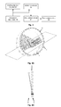
- some embodiments of the present disclosure propose a multi-spectral static CT apparatus as shown in Fig. 3 .
- the apparatus includes a conveyor mechanism 32, a distributed ray source 31, a detection device 33, an acquisition device 34, and a processing device 35.
- the conveyor mechanism 32 carries and moves linearly an object under inspection.
- the distributed ray source 31 includes a plurality of ray source spots that are provided in a plane perpendicular to a direction of the object's movement.
- the plurality of ray source spots at least partially surround the object, and emit X rays toward the object.
- Each of the ray source spots may be, for example, a carbon-nanotube X ray tube.
- the distributed ray source 31 consists of a plurality of distributed X-ray sources.
- Energy for ray beam emission can be set for each of the X-ray sources, and a sequence for ray beam emission can be set for all the X-ray sources.
- the X-ray sources may be arranged in one or more planes, and X-ray sources in each plane is classified into a group. X-ray sources in the same group may be set to have the same energy for beam emission, while X-ray sources in different groups may be set to have different energy levels for beam emission.
- the X-ray sources may be arranged in a continuous line or arc, or in multiple segments of discontinuous line or arc. However, X-ray sources in the same group have the same arrangement, so that no deviation of projection data occurs between data of multiple spectra.
- the detection device 33 includes a first column of detectors and a second column of detectors adjacent to the first column of detectors in the direction of the object's movement.
- the first column of detectors includes a plurality of detection units having a first energy response, provided in a first plane parallel to a plane of the distributed ray source and configured to receive X rays penetrating the object.
- the second column of detectors includes a plurality of detection units having a second energy response, provided in a second plane parallel to the plane of the distributed ray source and configured to receive X rays penetrating the object.
- the plane in which each X-ray source is arranged corresponds to a set of detectors arranged in columns.
- the detection units in each column of detectors may be arranged in a continuous line or arc, or in multiple segments of discontinuous line or arc.
- the respective columns are arranged parallel to each other in the direction of the object's movement, thereby avoiding the problem of oblique incidence of rays due to the arrangement of front and rear columns along the rays.
- the detection units in each column of detectors may have different energy responses to X rays emitted from the corresponding group of X-ray sources (X rays have an energy range that is a set value between 0 and the energy for beam emission) by using different materials or materials of different thicknesses for detection, or placing different filters in front of the detectors.
- X rays have an energy range that is a set value between 0 and the energy for beam emission
- filters in front of the detectors.
- at least one of the first and second columns of detectors have filters.
- the first energy response is a response substantially to low energy component in the X rays
- the second energy response is a response substantially to high energy component in the X rays.
- the processing device reconstructs high-energy and low-energy attenuation coefficient images of the object based on the first and second digital signals.
- the multiple columns of detectors corresponding to two or more groups of X-ray sources can detect a larger energy range and more energy spectra, and thus obtain a more accurate, finer result of multi-spectral analysis.
- At least one of the first and second columns of detectors have filters.
- the acquisition device 34 is coupled to the detection device 33, and configured to convert the X rays detected by the first column of detectors into a first digital signal and the X rays detected by the second column of detectors into a second digital signal.
- the acquisition device 34 may perform high-speed sampling on electric signals outputted from all the detection unit, and convert the electric signals into digital signals to be provided to the processing device 35.
- the processing device 35 is coupled to the acquisition device and configured to reconstruct a CT image of the object based on the first and second digital signals. For example, the processing device 35 may reconstruct values of atomic number and electron density of the object based on the first and second digital signals.
- a luggage carrying and control device carries the object and moves it to pass an imaging region surrounded by the distributed ray source, the detection device and the acquisition device.
- the luggage carrying and control device controls each X-ray source to emit ray beams at the set energy and sequence, and controls the multiple columns of detectors and the acquisition device to perform high-speed sampling at a set time interval or according to an external trigger signal.
- the luggage carrying and control device may provide, for each group of samples, location index or time index of the object.
- the data processing device may extract registered multi-spectral projection data in connection with distances between the imaging planes or time differences during the object's passage through the imaging planes.
- the processing device 35 is configured to reconstruct from the multi-spectral projection data 3D images of the atomic number and electron density of the object.
- the high and low energy projection data obtained from the dual-energy detector are denoted as p 1 and p 2 .
- the data first undergo pre-processing and correction, such as background and gain correction, or flawed detector track correction.
- a base material decomposition method is used to dual-energy decompose fan-beam projection data obtained by rearranging the projection data, and obtain dual-energy decomposition coefficients A 1 and A 2 under different base materials.
- a CT reconstruction algorithm is used to reconstruct on the two coefficients, and a result of the reconstruction, ⁇ 1 and ⁇ 2 , is obtained.
- Z 1 and Z 2 denote values of atomic numbers of two base materials
- ⁇ e1 and ⁇ e2 denote values of electron densities of the two base materials.
- the above dual-energy reconstruction method first decomposes the projection data and then performs reconstruction, and thus this method is called pre-processing algorithm.
- a post-processing method may also be used to first perform CT reconstruction on high and low energy projection data, respectively, and then calculate an image of distribution of materials based on the reconstructed high and low energy attenuation coefficient images.
- the post-processing method has advantages of simple and rapid calculation, and a high accuracy even when materials of the scanned object are similar.
- Fig. 4A illustrates a schematic block diagram of a CT apparatus according to an embodiment of the disclosure
- Fig. 4B illustrates a side view of scanning stages in the CT apparatus of Fig. 4A .
- the multi-spectral static CT apparatus in the embodiment includes a group of distributed X-ray sources A. All the X-ray sources in the group A are set to have the same energy for beam emission. Two columns of detectors corresponding to the distributed X-ray sources A are distributed in parallel in two adjacent planes, and include high energy detectors B and low energy detectors C.
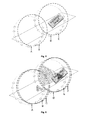
- Fig. 5 illustrates a schematic block diagram of a CT apparatus according to another embodiment of the disclosure.
- the multi-spectral static CT apparatus in the embodiment includes two scanning stages.
- the first and second scanning stages use distributed X-ray sources A and D, respectively.
- the distributed X-ray sources A and D have the same arrangements of X-ray sources. All the X-ray sources in the distributed X-ray source A are set to have the same energy for beam emission, and all the X-ray sources in the distributed X-ray source D are set to have the same energy for beam emission, which is different from the energy for beam emission of the distributed X-ray source A.
- Two columns of detectors B and E are distributed in parallel in two planes, and correspond to the distributed X-ray sources A and D, respectively.
- the conveyor mechanism 32 carries and moves linearly an object under inspection.
- the first scanning stage includes a first distributed ray source, a first column of detectors and a second column of detectors.
- the first distributed ray source includes a plurality of ray source spots that are provided in a plane perpendicular to a direction of the object's movement.
- the plurality of ray source spots at least partially surround the object, and emit X rays toward the object.
- the first column of detectors includes a plurality of detection units having a first energy response.
- the plurality of detection units are provided in a first plane parallel to a plane of the first distributed ray source, and configured to receive X rays penetrating the object.
- the second scanning stage is provided in series with the first scanning stage in the direction of the object's movement, and includes a second distributed ray source and a second column of detectors.
- the second distributed ray source includes a plurality of ray source spots that are provided in a plane perpendicular to a direction of the object's movement.
- the plurality of ray source spots at least partially surround the object, and emit X rays toward the object.
- the second column of detectors includes a plurality of detection units having a second energy response.
- the plurality of detection units are provided in a second plane parallel to the plane of the second distributed ray source and configured to receive X rays penetrating the object.
- the acquisition device 34 is coupled to the first and second columns of detectors, and configured to convert the X rays detected by the first column of detectors into a first digital signal and the X rays detected by the second column of detectors into a second digital signal.
- the processing device 35 is coupled to the acquisition device and configured to reconstruct a CT image of the object based on the first and second digital signals.
- Fig. 6 illustrates a schematic block diagram of a CT apparatus according to a further embodiment of the disclosure.
- the multi-spectral static CT apparatus in the embodiment includes two scanning stages.
- the first and second scanning stages use distributed X-ray sources A and D, respectively. All the X-ray sources in the distributed X-ray source A are set to have the same energy for beam emission, and all the X-ray sources in the distributed X-ray source D are set to have the same energy for beam emission, which is maintained as different from the energy for beam emission of the distributed X-ray source A.
- the distributed X-ray sources A and D have the same arrangements of X-ray sources.
- Four columns of detectors B, C, E, and F are distributed in parallel in four planes.
- the two columns of detectors B and C corresponding to the distributed X-ray source A are adjacent to each other, have different energy responses, and used to detect X rays emitted by the distributed X-ray source A.
- the two columns of detectors E and F corresponding to the distributed X-ray source D are adjacent to each other, have different energy responses, and used to detect X rays emitted by the distributed X-ray source D.
- the conveyor mechanism 32 carries and moves linearly an object under inspection.
- the first scanning stage includes a first distributed ray source, a first column of detectors and a second column of detectors.
- the first distributed ray source includes a plurality of ray source spots that are provided in a plane perpendicular to a direction of the object's movement.
- the plurality of ray source spots at least partially surround the object, and emit X rays toward the object.
- the first column of detectors includes a plurality of detection units having a first energy response.
- the plurality of detection units are provided in a first plane parallel to a plane of the first distributed ray source, and configured to receive X rays penetrating the object.
- the second column of detectors includes a plurality of detection units having a second energy response.
- the plurality of detection units are provided in a second plane parallel to the plane of the first distributed ray source and configured to receive X rays penetrating the object.
- the second scanning stage is provided in series with the first scanning stage in the direction of the object's movement, and includes a second distributed ray source, a third column of detectors, and a fourth column of detectors.
- the second distributed ray source includes a plurality of ray source spots that are provided in a plane perpendicular to a direction of the object's movement.
- the plurality of ray source spots at least partially surround the object, and emit X rays toward the object.
- the third column of detectors include a plurality of detection units having the first energy response.
- the plurality of detection units are provided in a third plane parallel to the plane of the second distributed ray source and configured to receive X rays penetrating the object.
- the fourth column of detectors includes a plurality of detection units having the second energy response.
- the plurality of detection units are provided in a fourth plane parallel to the plane of the second distributed ray source and configured to receive X rays penetrating the object.
- the acquisition device 34 is coupled to the first, second, third and fourth columns of detectors, and configured to convert the X rays detected by the first column of detectors into a first digital signal, the X rays detected by the second column of detectors into a second digital signal, the X rays detected by the third column of detectors into a third digital signal and the X rays detected by the fourth column of detectors into a fourth digital signal.
- the processing device 35 is coupled to the acquisition device and configured to reconstruct a CT image of the object based on the first, second, third and fourth digital signals.
- each of the scanning stage in the CT apparatus includes two columns of detectors.
- a parallel-arranged third column of detectors may be included in the first scanning stage, and a fourth column of detectors may be included in the second scanning stage.
- the ray spectra of the first and second distributed ray sources may be set to be identical to or different from each other as required, or may be set to be partially overlapped.
- the multi-spectral static CT imaging systems in the above embodiments use distributed ray sources to irradiate luggage or articles from different angles, without the slip-ring rotation in the conventional CT systems. This provides high security and reliability, reduces system cost and improves scanning speed. Meanwhile, by incorporating the multi-spectral analysis technology, the CT imaging systems can obtain atomic number and electron density at any location inside the luggage or article. This provides more intuitive information for further applications, such as detection of dangerous substances or smuggled products.
- the CT imaging systems can be applied widely for rapid and accurate detection of contraband articles, like explosives, inflammable substances or drugs.
- the embodiments of the present disclosure are characterized not only in combination of the static CT technology and the multi-spectral analysis technology, but also in skillful design and arrangement of the distributed ray source and multiple columns of detectors in the system. Wit the embodiments of the present disclosure, it is possible to avoid the problems of oblique incidence of rays and projection data deviation between multi-spectral data that occur in the CT systems with slip ring during the multi-spectral analysis process. In this way, accuracy in resolution of CT reconstructed image and spectral analysis result can be guaranteed.
- Examples of a signal bearing medium include, but are not limited to, the following: a recordable type medium such as a floppy disk, a hard disk drive, a Compact Disc (CD), a Digital Versatile Disk (DVD), a digital tape, a computer memory, etc.; and a transmission type medium such as a digital and/or an analog communication medium (e.g., a fiber optic cable, a waveguide, a wired communications link, a wireless communication link, etc.).
Landscapes
- Physics & Mathematics (AREA)
- Life Sciences & Earth Sciences (AREA)
- General Physics & Mathematics (AREA)
- Health & Medical Sciences (AREA)
- High Energy & Nuclear Physics (AREA)
- Spectroscopy & Molecular Physics (AREA)
- Molecular Biology (AREA)
- Geophysics (AREA)
- General Life Sciences & Earth Sciences (AREA)
- Radiology & Medical Imaging (AREA)
- General Health & Medical Sciences (AREA)
- Nuclear Medicine, Radiotherapy & Molecular Imaging (AREA)
- Pulmonology (AREA)
- Theoretical Computer Science (AREA)
- Chemical & Material Sciences (AREA)
- Analytical Chemistry (AREA)
- Biochemistry (AREA)
- Immunology (AREA)
- Pathology (AREA)
- Engineering & Computer Science (AREA)
- Analysing Materials By The Use Of Radiation (AREA)
Applications Claiming Priority (1)
| Application Number | Priority Date | Filing Date | Title |
|---|---|---|---|
| CN201310740971.5A CN104749648A (zh) | 2013-12-27 | 2013-12-27 | 多能谱静态ct设备 |
Publications (3)
| Publication Number | Publication Date |
|---|---|
| EP2889644A2 true EP2889644A2 (de) | 2015-07-01 |
| EP2889644A3 EP2889644A3 (de) | 2015-11-25 |
| EP2889644B1 EP2889644B1 (de) | 2021-04-07 |
Family
ID=52391748
Family Applications (1)
| Application Number | Title | Priority Date | Filing Date |
|---|---|---|---|
| EP14199145.5A Active EP2889644B1 (de) | 2013-12-27 | 2014-12-19 | Statische multispektrale ct-vorrichtungen |
Country Status (5)
| Country | Link |
|---|---|
| US (1) | US9784883B2 (de) |
| EP (1) | EP2889644B1 (de) |
| CN (1) | CN104749648A (de) |
| HK (1) | HK1211705A1 (de) |
| WO (1) | WO2015096770A1 (de) |
Cited By (3)
| Publication number | Priority date | Publication date | Assignee | Title |
|---|---|---|---|---|
| CN109540930A (zh) * | 2018-09-17 | 2019-03-29 | 南京航空航天大学 | 一种多能谱x射线成像散射估计与校正方法 |
| EP3506198A1 (de) * | 2017-12-26 | 2019-07-03 | Nuctech Company Limited | Bildverarbeitungsverfahren, vorrichtung und computerlesbares speichermedium |
| EP4459332A4 (de) * | 2021-12-30 | 2025-12-10 | Nuctech Co Ltd | Inspektionsvorrichtung mit mehreren röntgenquellen und inspektionsverfahren |
Families Citing this family (16)
| Publication number | Priority date | Publication date | Assignee | Title |
|---|---|---|---|---|
| CN106097407A (zh) * | 2016-05-30 | 2016-11-09 | 清华大学 | 图像处理方法和图像处理装置 |
| CN106097282B (zh) * | 2016-07-01 | 2019-02-26 | 上海奕瑞光电子科技股份有限公司 | 消除平板探测器图像残影的方法及平板探测器 |
| CN106526686B (zh) * | 2016-12-07 | 2019-05-07 | 同方威视技术股份有限公司 | 螺旋ct设备和三维图像重建方法 |
| WO2018153382A1 (zh) * | 2017-02-27 | 2018-08-30 | 北京纳米维景科技有限公司 | 适应大视野要求的静态实时ct成像系统及其成像方法 |
| AU2019373486A1 (en) * | 2018-10-31 | 2021-06-17 | Nanovision Technology (Beijing) Co., Ltd. | Multi-energy static security ct system and imaging method |
| CN109343135B (zh) * | 2018-10-31 | 2020-10-09 | 北京纳米维景科技有限公司 | 一种多级能量型静态安检ct系统及成像方法 |
| US12320761B2 (en) * | 2019-04-05 | 2025-06-03 | Arizona Board Of Regents On Behalf Of The University Of Arizona | Multiplexed computed tomography x-ray imaging |
| WO2020210941A1 (zh) * | 2019-04-15 | 2020-10-22 | 清华大学 | 分布式光源ct图像重建方法与系统 |
| WO2021085019A1 (ja) * | 2019-10-31 | 2021-05-06 | アイテック株式会社 | 手荷物非破壊検査システム、手荷物非破壊検査方法、プログラム、及び記録媒体 |
| CN112683934A (zh) * | 2020-12-04 | 2021-04-20 | 重庆大学 | 一种基于电子束扫描的x射线源静态ct成像系统及方法 |
| CN115598717B (zh) * | 2021-07-07 | 2024-05-14 | 同方威视技术股份有限公司 | 检查系统和方法 |
| CN113741234A (zh) * | 2021-07-21 | 2021-12-03 | 重庆真测科技股份有限公司 | 一种工业ct控制电路、工业ct系统及工业ct控制方法 |
| CN119184720B (zh) | 2021-10-15 | 2025-09-30 | 清华大学 | 用于射线检查的成像系统和方法 |
| CN114209350B (zh) * | 2021-12-21 | 2024-07-23 | 纳米维景(上海)医疗科技有限公司 | 一种静态螺旋ct及其扫描方法 |
| CN115144417A (zh) * | 2022-06-08 | 2022-10-04 | 北京纳米维景科技有限公司 | 一种柔性ct探测器及其静态ct系统 |
| CN118216940B (zh) * | 2024-03-20 | 2025-04-18 | 清华大学 | 分布式射线源ct成像系统及成像方法 |
Family Cites Families (17)
| Publication number | Priority date | Publication date | Assignee | Title |
|---|---|---|---|---|
| US6018562A (en) * | 1995-11-13 | 2000-01-25 | The United States Of America As Represented By The Secretary Of The Army | Apparatus and method for automatic recognition of concealed objects using multiple energy computed tomography |
| US6236709B1 (en) * | 1998-05-04 | 2001-05-22 | Ensco, Inc. | Continuous high speed tomographic imaging system and method |
| JP2003290207A (ja) * | 2002-04-04 | 2003-10-14 | Mitsubishi Heavy Ind Ltd | 多線源型x線ct装置 |
| WO2004090576A2 (en) * | 2003-04-02 | 2004-10-21 | Reveal Imaging Technologies, Inc. | System and method for detection of explosives in baggage |
| US7486769B2 (en) * | 2004-06-03 | 2009-02-03 | Brondo Jr Joseph H | Advanced multi-resonant, multi-mode gamma beam detection and imaging system for explosives, special nuclear material (SNM), high-z materials, and other contraband |
| US7813478B2 (en) * | 2007-02-08 | 2010-10-12 | Varian Medical Systems, Inc. | Method and apparatus to facilitate provision and use of multiple X-ray sources |
| CN101470082B (zh) * | 2007-12-27 | 2011-03-30 | 同方威视技术股份有限公司 | 物品检测装置及其检测方法 |
| CN102256548B (zh) * | 2008-12-17 | 2014-03-05 | 皇家飞利浦电子股份有限公司 | X射线检查装置及方法 |
| JP5885661B2 (ja) * | 2009-05-26 | 2016-03-15 | ラピスカン システムズ、インコーポレイテッド | 特定の対象物品の識別のためのx線断層撮影検査システム |
| EP2677935A1 (de) * | 2011-02-22 | 2014-01-01 | Koninklijke Philips N.V. | Detektionsvorrichtung |
| CN102379716A (zh) * | 2011-08-24 | 2012-03-21 | 苏州生物医学工程技术研究所 | 一种静态ct扫描仪系统及其扫描方法 |
| CN103308535B (zh) | 2012-03-09 | 2016-04-13 | 同方威视技术股份有限公司 | 用于射线扫描成像的设备和方法 |
| CN102697518B (zh) * | 2012-06-25 | 2015-01-07 | 苏州生物医学工程技术研究所 | 静态能量分辨ct扫描仪及其扫描方法 |
| CN203149136U (zh) * | 2012-12-31 | 2013-08-21 | 清华大学 | 多能ct成像系统 |
| CN203178216U (zh) * | 2012-12-31 | 2013-09-04 | 清华大学 | Ct设备 |
| CN104374783B (zh) | 2013-12-26 | 2017-06-16 | 清华大学 | Ct系统及其方法 |
| CN203909313U (zh) * | 2013-12-27 | 2014-10-29 | 清华大学 | 多能谱静态ct设备 |
-
2013
- 2013-12-27 CN CN201310740971.5A patent/CN104749648A/zh active Pending
-
2014
- 2014-12-19 EP EP14199145.5A patent/EP2889644B1/de active Active
- 2014-12-19 US US14/577,069 patent/US9784883B2/en active Active
- 2014-12-25 WO PCT/CN2014/094940 patent/WO2015096770A1/zh not_active Ceased
-
2015
- 2015-12-21 HK HK15112545.8A patent/HK1211705A1/xx unknown
Non-Patent Citations (1)
| Title |
|---|
| None |
Cited By (4)
| Publication number | Priority date | Publication date | Assignee | Title |
|---|---|---|---|---|
| EP3506198A1 (de) * | 2017-12-26 | 2019-07-03 | Nuctech Company Limited | Bildverarbeitungsverfahren, vorrichtung und computerlesbares speichermedium |
| US10884156B2 (en) | 2017-12-26 | 2021-01-05 | Nuctech Company Limited | Image processing method, device, and computer readable storage medium |
| CN109540930A (zh) * | 2018-09-17 | 2019-03-29 | 南京航空航天大学 | 一种多能谱x射线成像散射估计与校正方法 |
| EP4459332A4 (de) * | 2021-12-30 | 2025-12-10 | Nuctech Co Ltd | Inspektionsvorrichtung mit mehreren röntgenquellen und inspektionsverfahren |
Also Published As
| Publication number | Publication date |
|---|---|
| HK1211705A1 (zh) | 2016-05-27 |
| US20150185357A1 (en) | 2015-07-02 |
| US9784883B2 (en) | 2017-10-10 |
| EP2889644A3 (de) | 2015-11-25 |
| CN104749648A (zh) | 2015-07-01 |
| EP2889644B1 (de) | 2021-04-07 |
| WO2015096770A1 (zh) | 2015-07-02 |
Similar Documents
| Publication | Publication Date | Title |
|---|---|---|
| US9784883B2 (en) | Multi-spectral static CT apparatuses | |
| US9786041B2 (en) | CT systems and methods thereof | |
| US9746579B2 (en) | CT systems and methods thereof | |
| EP2817661B1 (de) | Röntgenabbildungsvorrichtung mit spärlicher detektoranordnung | |
| GB2439413A (en) | Cargo Security Inspection Method Based On Spiral Scanning | |
| CN107356615A (zh) | 一种用于双能x射线ct的方法和系统 | |
| JP2010133977A (ja) | 一度に1つのみの供給源が放射線を発光することを確実にすることによって、複数の供給源を備える門形の後方散乱検査器におけるクロストークを排除すること | |
| KR20170072170A (ko) | 탐측기 장치, 듀얼 에너지 ct 시스템 및 그 시스템을 이용하는 검출 방법 | |
| GB2368764A (en) | A digital radiation photographic detection system for large object | |
| CN101501530A (zh) | 用于获得图像数据的系统和方法 | |
| CN203909313U (zh) | 多能谱静态ct设备 | |
| CN203705363U (zh) | Ct系统 | |
| CN1139803C (zh) | 一种γ背散射成像无损检测方法与装置 | |
| HK1202620B (en) | Ct system and its corresponding method | |
| HK1212020B (en) | Ct system and method thereof | |
| HK1195631A (en) | A ct system and a detecting device used for the same | |
| HK1138371B (en) | Compact correcting and collimating device for radiometric imaging system | |
| HK1138371A1 (en) | Compact correcting and collimating device for radiometric imaging system | |
| HK1195631B (en) | A ct system and a detecting device used for the same | |
| HK1071431B (en) | Method and device for detecting a given material in an object using electromagnetic rays | |
| HK1071431A1 (en) | Method and device for detecting a given material in an object using electromagnetic rays |
Legal Events
| Date | Code | Title | Description |
|---|---|---|---|
| PUAI | Public reference made under article 153(3) epc to a published international application that has entered the european phase |
Free format text: ORIGINAL CODE: 0009012 |
|
| 17P | Request for examination filed |
Effective date: 20141219 |
|
| AK | Designated contracting states |
Kind code of ref document: A2 Designated state(s): AL AT BE BG CH CY CZ DE DK EE ES FI FR GB GR HR HU IE IS IT LI LT LU LV MC MK MT NL NO PL PT RO RS SE SI SK SM TR |
|
| AX | Request for extension of the european patent |
Extension state: BA ME |
|
| PUAL | Search report despatched |
Free format text: ORIGINAL CODE: 0009013 |
|
| RIC1 | Information provided on ipc code assigned before grant |
Ipc: G01T 1/29 20060101AFI20151015BHEP |
|
| AK | Designated contracting states |
Kind code of ref document: A3 Designated state(s): AL AT BE BG CH CY CZ DE DK EE ES FI FR GB GR HR HU IE IS IT LI LT LU LV MC MK MT NL NO PL PT RO RS SE SI SK SM TR |
|
| AX | Request for extension of the european patent |
Extension state: BA ME |
|
| RIC1 | Information provided on ipc code assigned before grant |
Ipc: G01T 1/29 20060101AFI20151020BHEP |
|
| R17P | Request for examination filed (corrected) |
Effective date: 20160525 |
|
| RBV | Designated contracting states (corrected) |
Designated state(s): AL AT BE BG CH CY CZ DE DK EE ES FI FR GB GR HR HU IE IS IT LI LT LU LV MC MK MT NL NO PL PT RO RS SE SI SK SM TR |
|
| STAA | Information on the status of an ep patent application or granted ep patent |
Free format text: STATUS: EXAMINATION IS IN PROGRESS |
|
| 17Q | First examination report despatched |
Effective date: 20170530 |
|
| GRAP | Despatch of communication of intention to grant a patent |
Free format text: ORIGINAL CODE: EPIDOSNIGR1 |
|
| STAA | Information on the status of an ep patent application or granted ep patent |
Free format text: STATUS: GRANT OF PATENT IS INTENDED |
|
| INTG | Intention to grant announced |
Effective date: 20201105 |
|
| RIN1 | Information on inventor provided before grant (corrected) |
Inventor name: ZHANG, LI Inventor name: JIN, XIN Inventor name: CHEN, ZHIQIANG Inventor name: SUN, YUNDA Inventor name: HUANG, QINGPING Inventor name: SHEN, LE Inventor name: ZHAO, JI Inventor name: YANG, TAO |
|
| GRAS | Grant fee paid |
Free format text: ORIGINAL CODE: EPIDOSNIGR3 |
|
| GRAA | (expected) grant |
Free format text: ORIGINAL CODE: 0009210 |
|
| STAA | Information on the status of an ep patent application or granted ep patent |
Free format text: STATUS: THE PATENT HAS BEEN GRANTED |
|
| AK | Designated contracting states |
Kind code of ref document: B1 Designated state(s): AL AT BE BG CH CY CZ DE DK EE ES FI FR GB GR HR HU IE IS IT LI LT LU LV MC MK MT NL NO PL PT RO RS SE SI SK SM TR |
|
| REG | Reference to a national code |
Ref country code: GB Ref legal event code: FG4D |
|
| REG | Reference to a national code |
Ref country code: AT Ref legal event code: REF Ref document number: 1380405 Country of ref document: AT Kind code of ref document: T Effective date: 20210415 Ref country code: CH Ref legal event code: EP |
|
| REG | Reference to a national code |
Ref country code: DE Ref legal event code: R096 Ref document number: 602014076325 Country of ref document: DE |
|
| REG | Reference to a national code |
Ref country code: IE Ref legal event code: FG4D |
|
| REG | Reference to a national code |
Ref country code: LT Ref legal event code: MG9D |
|
| REG | Reference to a national code |
Ref country code: NL Ref legal event code: MP Effective date: 20210407 Ref country code: AT Ref legal event code: MK05 Ref document number: 1380405 Country of ref document: AT Kind code of ref document: T Effective date: 20210407 |
|
| PG25 | Lapsed in a contracting state [announced via postgrant information from national office to epo] |
Ref country code: LT Free format text: LAPSE BECAUSE OF FAILURE TO SUBMIT A TRANSLATION OF THE DESCRIPTION OR TO PAY THE FEE WITHIN THE PRESCRIBED TIME-LIMIT Effective date: 20210407 Ref country code: NL Free format text: LAPSE BECAUSE OF FAILURE TO SUBMIT A TRANSLATION OF THE DESCRIPTION OR TO PAY THE FEE WITHIN THE PRESCRIBED TIME-LIMIT Effective date: 20210407 Ref country code: FI Free format text: LAPSE BECAUSE OF FAILURE TO SUBMIT A TRANSLATION OF THE DESCRIPTION OR TO PAY THE FEE WITHIN THE PRESCRIBED TIME-LIMIT Effective date: 20210407 Ref country code: BG Free format text: LAPSE BECAUSE OF FAILURE TO SUBMIT A TRANSLATION OF THE DESCRIPTION OR TO PAY THE FEE WITHIN THE PRESCRIBED TIME-LIMIT Effective date: 20210707 Ref country code: AT Free format text: LAPSE BECAUSE OF FAILURE TO SUBMIT A TRANSLATION OF THE DESCRIPTION OR TO PAY THE FEE WITHIN THE PRESCRIBED TIME-LIMIT Effective date: 20210407 Ref country code: HR Free format text: LAPSE BECAUSE OF FAILURE TO SUBMIT A TRANSLATION OF THE DESCRIPTION OR TO PAY THE FEE WITHIN THE PRESCRIBED TIME-LIMIT Effective date: 20210407 |
|
| PG25 | Lapsed in a contracting state [announced via postgrant information from national office to epo] |
Ref country code: IS Free format text: LAPSE BECAUSE OF FAILURE TO SUBMIT A TRANSLATION OF THE DESCRIPTION OR TO PAY THE FEE WITHIN THE PRESCRIBED TIME-LIMIT Effective date: 20210807 Ref country code: GR Free format text: LAPSE BECAUSE OF FAILURE TO SUBMIT A TRANSLATION OF THE DESCRIPTION OR TO PAY THE FEE WITHIN THE PRESCRIBED TIME-LIMIT Effective date: 20210708 Ref country code: LV Free format text: LAPSE BECAUSE OF FAILURE TO SUBMIT A TRANSLATION OF THE DESCRIPTION OR TO PAY THE FEE WITHIN THE PRESCRIBED TIME-LIMIT Effective date: 20210407 Ref country code: RS Free format text: LAPSE BECAUSE OF FAILURE TO SUBMIT A TRANSLATION OF THE DESCRIPTION OR TO PAY THE FEE WITHIN THE PRESCRIBED TIME-LIMIT Effective date: 20210407 Ref country code: SE Free format text: LAPSE BECAUSE OF FAILURE TO SUBMIT A TRANSLATION OF THE DESCRIPTION OR TO PAY THE FEE WITHIN THE PRESCRIBED TIME-LIMIT Effective date: 20210407 Ref country code: PL Free format text: LAPSE BECAUSE OF FAILURE TO SUBMIT A TRANSLATION OF THE DESCRIPTION OR TO PAY THE FEE WITHIN THE PRESCRIBED TIME-LIMIT Effective date: 20210407 Ref country code: PT Free format text: LAPSE BECAUSE OF FAILURE TO SUBMIT A TRANSLATION OF THE DESCRIPTION OR TO PAY THE FEE WITHIN THE PRESCRIBED TIME-LIMIT Effective date: 20210809 Ref country code: NO Free format text: LAPSE BECAUSE OF FAILURE TO SUBMIT A TRANSLATION OF THE DESCRIPTION OR TO PAY THE FEE WITHIN THE PRESCRIBED TIME-LIMIT Effective date: 20210707 Ref country code: ES Free format text: LAPSE BECAUSE OF FAILURE TO SUBMIT A TRANSLATION OF THE DESCRIPTION OR TO PAY THE FEE WITHIN THE PRESCRIBED TIME-LIMIT Effective date: 20210407 |
|
| REG | Reference to a national code |
Ref country code: DE Ref legal event code: R097 Ref document number: 602014076325 Country of ref document: DE |
|
| PG25 | Lapsed in a contracting state [announced via postgrant information from national office to epo] |
Ref country code: SM Free format text: LAPSE BECAUSE OF FAILURE TO SUBMIT A TRANSLATION OF THE DESCRIPTION OR TO PAY THE FEE WITHIN THE PRESCRIBED TIME-LIMIT Effective date: 20210407 Ref country code: SK Free format text: LAPSE BECAUSE OF FAILURE TO SUBMIT A TRANSLATION OF THE DESCRIPTION OR TO PAY THE FEE WITHIN THE PRESCRIBED TIME-LIMIT Effective date: 20210407 Ref country code: DK Free format text: LAPSE BECAUSE OF FAILURE TO SUBMIT A TRANSLATION OF THE DESCRIPTION OR TO PAY THE FEE WITHIN THE PRESCRIBED TIME-LIMIT Effective date: 20210407 Ref country code: EE Free format text: LAPSE BECAUSE OF FAILURE TO SUBMIT A TRANSLATION OF THE DESCRIPTION OR TO PAY THE FEE WITHIN THE PRESCRIBED TIME-LIMIT Effective date: 20210407 Ref country code: CZ Free format text: LAPSE BECAUSE OF FAILURE TO SUBMIT A TRANSLATION OF THE DESCRIPTION OR TO PAY THE FEE WITHIN THE PRESCRIBED TIME-LIMIT Effective date: 20210407 Ref country code: RO Free format text: LAPSE BECAUSE OF FAILURE TO SUBMIT A TRANSLATION OF THE DESCRIPTION OR TO PAY THE FEE WITHIN THE PRESCRIBED TIME-LIMIT Effective date: 20210407 |
|
| PLBE | No opposition filed within time limit |
Free format text: ORIGINAL CODE: 0009261 |
|
| STAA | Information on the status of an ep patent application or granted ep patent |
Free format text: STATUS: NO OPPOSITION FILED WITHIN TIME LIMIT |
|
| 26N | No opposition filed |
Effective date: 20220110 |
|
| PG25 | Lapsed in a contracting state [announced via postgrant information from national office to epo] |
Ref country code: IS Free format text: LAPSE BECAUSE OF FAILURE TO SUBMIT A TRANSLATION OF THE DESCRIPTION OR TO PAY THE FEE WITHIN THE PRESCRIBED TIME-LIMIT Effective date: 20210807 Ref country code: AL Free format text: LAPSE BECAUSE OF FAILURE TO SUBMIT A TRANSLATION OF THE DESCRIPTION OR TO PAY THE FEE WITHIN THE PRESCRIBED TIME-LIMIT Effective date: 20210407 |
|
| REG | Reference to a national code |
Ref country code: DE Ref legal event code: R119 Ref document number: 602014076325 Country of ref document: DE |
|
| PG25 | Lapsed in a contracting state [announced via postgrant information from national office to epo] |
Ref country code: MC Free format text: LAPSE BECAUSE OF FAILURE TO SUBMIT A TRANSLATION OF THE DESCRIPTION OR TO PAY THE FEE WITHIN THE PRESCRIBED TIME-LIMIT Effective date: 20210407 Ref country code: IT Free format text: LAPSE BECAUSE OF FAILURE TO SUBMIT A TRANSLATION OF THE DESCRIPTION OR TO PAY THE FEE WITHIN THE PRESCRIBED TIME-LIMIT Effective date: 20210407 |
|
| REG | Reference to a national code |
Ref country code: CH Ref legal event code: PL |
|
| GBPC | Gb: european patent ceased through non-payment of renewal fee |
Effective date: 20211219 |
|
| REG | Reference to a national code |
Ref country code: BE Ref legal event code: MM Effective date: 20211231 |
|
| PG25 | Lapsed in a contracting state [announced via postgrant information from national office to epo] |
Ref country code: LU Free format text: LAPSE BECAUSE OF NON-PAYMENT OF DUE FEES Effective date: 20211219 Ref country code: IE Free format text: LAPSE BECAUSE OF NON-PAYMENT OF DUE FEES Effective date: 20211219 Ref country code: GB Free format text: LAPSE BECAUSE OF NON-PAYMENT OF DUE FEES Effective date: 20211219 Ref country code: DE Free format text: LAPSE BECAUSE OF NON-PAYMENT OF DUE FEES Effective date: 20220701 |
|
| PG25 | Lapsed in a contracting state [announced via postgrant information from national office to epo] |
Ref country code: FR Free format text: LAPSE BECAUSE OF NON-PAYMENT OF DUE FEES Effective date: 20211231 Ref country code: BE Free format text: LAPSE BECAUSE OF NON-PAYMENT OF DUE FEES Effective date: 20211231 |
|
| PG25 | Lapsed in a contracting state [announced via postgrant information from national office to epo] |
Ref country code: LI Free format text: LAPSE BECAUSE OF NON-PAYMENT OF DUE FEES Effective date: 20211231 Ref country code: CH Free format text: LAPSE BECAUSE OF NON-PAYMENT OF DUE FEES Effective date: 20211231 |
|
| PG25 | Lapsed in a contracting state [announced via postgrant information from national office to epo] |
Ref country code: HU Free format text: LAPSE BECAUSE OF FAILURE TO SUBMIT A TRANSLATION OF THE DESCRIPTION OR TO PAY THE FEE WITHIN THE PRESCRIBED TIME-LIMIT; INVALID AB INITIO Effective date: 20141219 |
|
| PG25 | Lapsed in a contracting state [announced via postgrant information from national office to epo] |
Ref country code: CY Free format text: LAPSE BECAUSE OF FAILURE TO SUBMIT A TRANSLATION OF THE DESCRIPTION OR TO PAY THE FEE WITHIN THE PRESCRIBED TIME-LIMIT Effective date: 20210407 |
|
| PG25 | Lapsed in a contracting state [announced via postgrant information from national office to epo] |
Ref country code: MK Free format text: LAPSE BECAUSE OF FAILURE TO SUBMIT A TRANSLATION OF THE DESCRIPTION OR TO PAY THE FEE WITHIN THE PRESCRIBED TIME-LIMIT Effective date: 20210407 |
|
| PG25 | Lapsed in a contracting state [announced via postgrant information from national office to epo] |
Ref country code: TR Free format text: LAPSE BECAUSE OF FAILURE TO SUBMIT A TRANSLATION OF THE DESCRIPTION OR TO PAY THE FEE WITHIN THE PRESCRIBED TIME-LIMIT Effective date: 20210407 |
|
| PG25 | Lapsed in a contracting state [announced via postgrant information from national office to epo] |
Ref country code: MT Free format text: LAPSE BECAUSE OF FAILURE TO SUBMIT A TRANSLATION OF THE DESCRIPTION OR TO PAY THE FEE WITHIN THE PRESCRIBED TIME-LIMIT Effective date: 20210407 |