EP2889641B1 - Bildverarbeitungsvorrichtung, Bildverarbeitungsverfahren, Programm und Bildverarbeitungssystem - Google Patents
Bildverarbeitungsvorrichtung, Bildverarbeitungsverfahren, Programm und Bildverarbeitungssystem Download PDFInfo
- Publication number
- EP2889641B1 EP2889641B1 EP14200098.3A EP14200098A EP2889641B1 EP 2889641 B1 EP2889641 B1 EP 2889641B1 EP 14200098 A EP14200098 A EP 14200098A EP 2889641 B1 EP2889641 B1 EP 2889641B1
- Authority
- EP
- European Patent Office
- Prior art keywords
- image
- region
- parallax
- road surface
- image processing
- Prior art date
- Legal status (The legal status is an assumption and is not a legal conclusion. Google has not performed a legal analysis and makes no representation as to the accuracy of the status listed.)
- Active
Links
Images


Classifications
-
- G—PHYSICS
- G01—MEASURING; TESTING
- G01S—RADIO DIRECTION-FINDING; RADIO NAVIGATION; DETERMINING DISTANCE OR VELOCITY BY USE OF RADIO WAVES; LOCATING OR PRESENCE-DETECTING BY USE OF THE REFLECTION OR RERADIATION OF RADIO WAVES; ANALOGOUS ARRANGEMENTS USING OTHER WAVES
- G01S17/00—Systems using the reflection or reradiation of electromagnetic waves other than radio waves, e.g. lidar systems
- G01S17/02—Systems using the reflection of electromagnetic waves other than radio waves
- G01S17/06—Systems determining position data of a target
- G01S17/42—Simultaneous measurement of distance and other co-ordinates
-
- H—ELECTRICITY
- H04—ELECTRIC COMMUNICATION TECHNIQUE
- H04N—PICTORIAL COMMUNICATION, e.g. TELEVISION
- H04N13/00—Stereoscopic video systems; Multi-view video systems; Details thereof
- H04N13/20—Image signal generators
- H04N13/204—Image signal generators using stereoscopic image cameras
- H04N13/239—Image signal generators using stereoscopic image cameras using two two-dimensional [2D] image sensors having a relative position equal to or related to the interocular distance
-
- G—PHYSICS
- G01—MEASURING; TESTING
- G01S—RADIO DIRECTION-FINDING; RADIO NAVIGATION; DETERMINING DISTANCE OR VELOCITY BY USE OF RADIO WAVES; LOCATING OR PRESENCE-DETECTING BY USE OF THE REFLECTION OR RERADIATION OF RADIO WAVES; ANALOGOUS ARRANGEMENTS USING OTHER WAVES
- G01S17/00—Systems using the reflection or reradiation of electromagnetic waves other than radio waves, e.g. lidar systems
- G01S17/86—Combinations of lidar systems with systems other than lidar, radar or sonar, e.g. with direction finders
-
- G—PHYSICS
- G01—MEASURING; TESTING
- G01S—RADIO DIRECTION-FINDING; RADIO NAVIGATION; DETERMINING DISTANCE OR VELOCITY BY USE OF RADIO WAVES; LOCATING OR PRESENCE-DETECTING BY USE OF THE REFLECTION OR RERADIATION OF RADIO WAVES; ANALOGOUS ARRANGEMENTS USING OTHER WAVES
- G01S17/00—Systems using the reflection or reradiation of electromagnetic waves other than radio waves, e.g. lidar systems
- G01S17/88—Lidar systems specially adapted for specific applications
- G01S17/93—Lidar systems specially adapted for specific applications for anti-collision purposes
- G01S17/931—Lidar systems specially adapted for specific applications for anti-collision purposes of land vehicles
-
- G—PHYSICS
- G06—COMPUTING OR CALCULATING; COUNTING
- G06T—IMAGE DATA PROCESSING OR GENERATION, IN GENERAL
- G06T7/00—Image analysis
- G06T7/10—Segmentation; Edge detection
- G06T7/12—Edge-based segmentation
-
- G—PHYSICS
- G06—COMPUTING OR CALCULATING; COUNTING
- G06V—IMAGE OR VIDEO RECOGNITION OR UNDERSTANDING
- G06V20/00—Scenes; Scene-specific elements
- G06V20/50—Context or environment of the image
- G06V20/56—Context or environment of the image exterior to a vehicle by using sensors mounted on the vehicle
- G06V20/588—Recognition of the road, e.g. of lane markings; Recognition of the vehicle driving pattern in relation to the road
-
- H—ELECTRICITY
- H04—ELECTRIC COMMUNICATION TECHNIQUE
- H04N—PICTORIAL COMMUNICATION, e.g. TELEVISION
- H04N13/00—Stereoscopic video systems; Multi-view video systems; Details thereof
- H04N13/20—Image signal generators
- H04N13/271—Image signal generators wherein the generated image signals comprise depth maps or disparity maps
-
- G—PHYSICS
- G06—COMPUTING OR CALCULATING; COUNTING
- G06T—IMAGE DATA PROCESSING OR GENERATION, IN GENERAL
- G06T2207/00—Indexing scheme for image analysis or image enhancement
- G06T2207/10—Image acquisition modality
- G06T2207/10004—Still image; Photographic image
- G06T2207/10012—Stereo images
-
- G—PHYSICS
- G06—COMPUTING OR CALCULATING; COUNTING
- G06T—IMAGE DATA PROCESSING OR GENERATION, IN GENERAL
- G06T2207/00—Indexing scheme for image analysis or image enhancement
- G06T2207/10—Image acquisition modality
- G06T2207/10024—Color image
-
- G—PHYSICS
- G06—COMPUTING OR CALCULATING; COUNTING
- G06T—IMAGE DATA PROCESSING OR GENERATION, IN GENERAL
- G06T2207/00—Indexing scheme for image analysis or image enhancement
- G06T2207/10—Image acquisition modality
- G06T2207/10028—Range image; Depth image; 3D point clouds
-
- G—PHYSICS
- G06—COMPUTING OR CALCULATING; COUNTING
- G06T—IMAGE DATA PROCESSING OR GENERATION, IN GENERAL
- G06T2207/00—Indexing scheme for image analysis or image enhancement
- G06T2207/30—Subject of image; Context of image processing
- G06T2207/30248—Vehicle exterior or interior
- G06T2207/30252—Vehicle exterior; Vicinity of vehicle
-
- H—ELECTRICITY
- H04—ELECTRIC COMMUNICATION TECHNIQUE
- H04N—PICTORIAL COMMUNICATION, e.g. TELEVISION
- H04N13/00—Stereoscopic video systems; Multi-view video systems; Details thereof
- H04N2013/0074—Stereoscopic image analysis
- H04N2013/0092—Image segmentation from stereoscopic image signals
Definitions
- the disclosures herein generally relate to an image processing apparatus, an image processing method, a program thereof and an image processing system that detects a predetermined image region from an image picked up by an imaging apparatus that can obtain distance information.
- a variety of driving supports using results of analyses of images picked up by cameras mounted on vehicles have been known.
- an image processing apparatus recognizing an object such as a front vehicle or a pedestrian from the image, a vehicle-mounted apparatus can alert a driver that the own vehicle is in danger of abnormally approaching the object, or control a brake to reduce damage.
- the image processing apparatus recognizes a pedestrian who runs out into a road, and draws the driver's attention to the pedestrian.
- Japanese Published Patent Application Nos. 2000-329852 and 2004-28727 discloses an obstacle recognition system that recognizes an object by a stereo camera and a scanning laser radar separately, and weights results of their recognitions according to respective reliabilities of these range finding means, and thereby determines whether the object exists.
- Japanese Published Patent Application No. 2004-28727 discloses a monitoring system that divides distance image data into plural partitions and corrects a distance to a three-dimensional object in the distance image data referring to a distance to a predetermined position measured by a laser radar system.
- detecting a specific region is effective in recognizing an object with high accuracy.
- the accuracy in recognizing an object in the image processing apparatus can be enhanced by using a relative positional relationship between the object and the road surface.
- Document JP 2012 225806 A discloses a road gradient estimation device and program in which a road surface reflection point extraction part 22 extracts a road surface reflection point from observation data of a laser radar 12, and a first solid object candidate extraction part 24 extracts a first solid object candidate from the remaining point groups.
- Document GB 2 289 816 A discloses an obstacle detecting system for a motor vehicle which is capable of detecting not only the distance to an obstacle in front of the vehicle and the width thereof but also its height, for allowing motor vehicle control to be effected more appropriately with high reliability.
- the distance to the object in front of the vehicle and its width are detected by an azimuthally scanning lidar unit, while the distance to an object caught within one of the windows preset by window setting means is also detected by a distance detecting circuit of a stereoscopic video camera unit.
- Document US 2013/120575 A1 discloses an apparatus for use in a vehicle which identifies road markers.
- the apparatus includes a sensor unit configured to collect image information ahead of the vehicle, distance information, and information on the reflected amount of a road surface.
- the apparatus includes a recognizer unit configured to recognize the road markers ahead of the vehicle on the basis of the image information, distance information, and information on the reflected amount provided from the sensor unit.
- disparity information is generated from a plurality of imaged images imaged by a plurality of imagers.
- Disparity histogram information that shows disparity value frequency distribution in each of line regions obtained by plurally dividing the plurality of imaged images in a vertical direction is generated.
- a group of disparity values or disparity value range that is consistent with a feature in which a disparity value becomes smaller as it approaches an upper portion of the imaged image from a disparity value or a disparity value range having frequency that exceeds a predetermined specified value is selected.
- a slope condition of a road surface in front of a driver's vehicle with respect to a road surface portion on which the driver's vehicle travels is identified in accordance with the selected group of disparity values or disparity value range.
- Document EP 2 669 845 A2 discloses a target recognition system, a target recognition method, and a target recognition program, to recognize one or more recognition targets, operatively connected to an imaging device to capture an image of an area ahead of the target recognition system, each of which includes a recognition area detector to detect multiple recognition areas from the captured image; a recognition weighting unit to weight the probability of images of the recognition targets being present in each of the respective recognition areas detected by the recognition area detector; and a target recognition processor to recognize the one or more recognition targets in a specified recognition area based on the recognition weighting given to the respective recognition areas.
- Document US 2008/024607 A1 discloses an image display apparatus including a camera, a laser radar, a depression angle correction calculation device, a three-dimensional object detection device, and a viewpoint conversion device, which are installed in a vehicle.
- the laser radar detects changes in the condition of a road surface with respect to the camera.
- the depression angle correction calculation device adds a correction angle to a depression angle of the camera.
- the viewpoint conversion device reduces the correction angle if the change in road surface condition detected by the laser radar is due to a three-dimensional object detected by the three-dimensional object detection device.
- an image processing apparatus for detecting an image region in an image picked up by a stereo camera is defined by claim 1.
- an image processing method for detecting an image region in an image picked up by a stereo camera is defined by claim 7.
- a computer program for causing a computer to perform the method is defined by claim 8.
- an image processing system for detecting an image region in an image picked up by a stereo camera and detecting a detection target based on the image region is defined by claim 9.
- an image processing apparatus an image processing method, a program thereof and an image processing system that recognize a specific region from an image picked up by an imaging means can be provided.
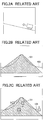
- FIG. 1A is a diagram illustrating an example of an inclination of a road surface on which a vehicle travels. The vehicle travels leftward on a flat road.
- Fig. 1B is a diagram illustrating an example for explaining schematically an image picked up by a camera installed on the vehicle. Since the camera is fixed in the vehicle (for example, the camera is fixed so that an optical axis is directed in a direction horizontal to the road surface), a vanishing point of the road surface region 101 resides in a position a height of which in the vertical direction in the image takes a predetermined value.
- the image processing apparatus determines the road surface region 101 by using a property that a parallax value of the road surface for one line in the horizontal direction of the image is almost constant (which will be described later in detail). Meanwhile, the optical axis of the camera is an example of an imaging direction recited in claims.
- Fig. 1C is a diagram illustrating an example for explaining schematically an arrangement of object candidate regions 103 in the road surface region 101.
- the image processing apparatus performs object recognition processing for the image and recognizes the object candidate regions 103 A to C.
- An object which a driver of the vehicle should be careful about is considered to be an object on the road.
- the image processing apparatus detects one of the object candidate regions 103, which is at least partially overlapped with the road surface region 101, as an object region, and determines that an object is imaged in the object candidate region 103 overlapped with the road surface region 101. Then, the vehicle performs driving support such as attention attraction based on the object region.
- FIG. 2A is a diagram illustrating an example of an inclination of a road surface on which a vehicle travels. The vehicle travels leftward on an ascending road.
- Fig. 2B is a diagram illustrating an example for explaining schematically an image picked up by a camera installed on the vehicle.
- a vanishing point of the road surface moves upward from the position of the vanishing point where the vehicle travels on the flat road 105.
- the image processing device does not detect that the vehicle travels on the ascending road, the road surface region 101 is detected in the same way as that where the vehicle travels on the flat road. Therefore, a region different from the real road 105 is detected as the road surface region 101.
- Fig. 2C is a diagram illustrating an example for explaining schematically an arrangement of object candidate regions 103 in the road surface region 101.
- the object candidate regions A and B exist on the road surface region 101 detected by the image processing apparatus.
- the object candidate region C is not overlaid on the road surface region 101 though it is on the actual road 105.
- the image processing apparatus determines that an object the driver of the vehicle should be careful about (for example, a building or the like) is not imaged in the object candidate region C. Therefore, a situation where a driving support such as attention attraction based on an object in the object candidate region C cannot be performed may arise.
- an object candidate region D is overlaid on the road surface region 101 detected by the image processing apparatus, though it does not exist on the actual road 105, and it may be determined that the object candidate region D travels on the road surface region 101. Therefore, there is a possibility that the vehicle performs unnecessary driving support such as attention attraction based on an object in the object candidate region D.
- a slanted road surface is a descending road surface
- the same situation as above can arise.
- the vehicle travels leftward on the descending road.
- the conventional image processing apparatus does not detect the travelling on the descending road, and detects a road surface region 101 in the same way as the case of travelling on the flat road surface as shown in Fig. 3B .
- a region different from the actual road 105 is detected as the road surface region 101.
- Fig. 3C is a diagram illustrating an example for explaining schematically an arrangement of object candidate regions 103 in the road surface region 101.
- the object candidate regions A and B exist on the road surface region 101 detected by the image processing apparatus.
- the object candidate region C does not exist on the actual road 105 but is overlaid on the road surface region 101, a situation where the vehicle performs a driving support such as attention attraction based on an object in the object candidate region C may arise.
- a situation where a driving support is not performed for an object candidate region for which the driving support should be performed may also arise.
- a shape of the actual road 105 is not substantially different from a shape of the road surface region 101, but the vanishing point may change depending on a detected line, and the shape of the road surface region 101 may be greatly deviated from the actual road 105.
- the image processing apparatus 100 can detect the road surface region 101 accurately even if the road surface is slanted.
- Figs. 4A to 4C are diagrams illustrating an example for schematically explaining an outline of detection of the road surface region 101 by the image processing apparatus according to the present embodiment of the invention. As shown in Fig. 4A , a vehicle travels leftward on an ascending road.
- the apparatus When the image processing apparatus detects that the vehicle travels on a slope from a range finding result by a laser radar as shown in the right part of Fig. 4B , the apparatus performs line detections for detecting the road surface regions plural times for respective regions of parallax values processing for detecting lines 104 from a peak of a histogram of parallax values for respective y-coordinates of a parallax image. In the drawing, three lines 104 are detected.
- One of the features in the present embodiment of the invention is determining the number of the lines 104 according to the slope of the road surface obtained from the range finding result of the laser radar.
- a range of the road surface in the y-coordinate direction of the parallax image in the left part of Fig. 4B can be specified accurately.
- the vanishing point of the parallax image can be easily made coincident with the y-intercept of the line in the right part of Fig. 4B , and outer edges of the road surface region 101 can be defined with the plural lines 102. Accordingly, the shape of the road surface region 101 of the parallax image can be brought close to the actual road 105.
- Fig. 4C is a diagram illustrating an example for schematically explaining an arrangement of object candidate regions on the road surface region 101. Since an object candidate region C is overlaid with the road surface region 101 detected by the image processing apparatus, the vehicle can perform driving support such as attention attraction based on an object in the object candidate region C. Moreover, since an object candidate region D is not overlaid with the road surface region 101 detected by the image processing apparatus, the vehicle can suppress the driving support based on an object in the object candidate region D.
- a road surface region means a region having a small degree of irregularity so that a vehicle can travel on it.
- a typical example includes a general-purpose road, an expressway (limited highway), a private road, a farm road, a forest road, a park road, a garden road, a village road or the like.
- a region is not called "road", when a vehicle can travel on it, it is included in the road surface region.
- the road surface region is an example of an image region recited in claims.
- an object to be detected such as a vehicle detected for performing driving support is mentioned.
- the object means a detection target or a detection object.
- Fig. 5 is a functional block diagram illustrating an example of the image processing system 200.
- the image processing system 200 includes the apparatus 100, a stereo camera 99, a laser radar range finding unit 28 and an ECU (Electronic Control unit) 98.
- the image processing apparatus 100 includes a stereo image input unit 21, a brightness image input unit 22, a parallax image calculation unit 23, an object candidate region recognition unit 24, a road surface detection processing unit 25, an object recognition processing unit 26 and an object recognition result output unit 27.
- the stereo camera 99 picks up synchronized stereo images (a left image and a right image picked up at the same time) and outputs them to the stereo image input unit 21.
- the stereo camera 99 is an example of an imaging unit.
- the stereo camera 99 will be explained later in detail.
- a distance image is picked up by the stereo camera 99.
- a monocular TOF (Time of Flight) camera in which a part of pixels is used for detecting a distance or a monocular camera, which calculates parallax by comparing plural frames on the assumption that the camera moves, may be used in examples not forming part of the invention.
- the monocular camera does not require calibration for adjusting a base-line length, and cost can be reduced.
- the stereo image input unit 21 outputs the stereo images to the brightness image input unit 22 and to the parallax image calculation unit 23.
- the brightness image input unit 22 outputs a left image or a right image of the stereo images to the object candidate region recognition unit 24 as a brightness image.
- the image is stored in a memory region in the image processing apparatus 100. It is determined in advance whether to input the left image or the right image. It may be dynamically switched according to an estimated image quality such as contrast.
- the parallax image calculation unit 23 calculates a difference between imaging positions (i.e. parallax) in the left and right images using the stereo images input from the stereo image input unit 21.
- the parallax is calculated for each pixel or each pixel block, and a parallax image in which each pixel or each pixel block is associated with parallax information is obtained. Since an overlap region is required in the stereo images for obtaining the parallax, strictly speaking, the parallax image is an overlapping part in the stereo images.
- the image processing apparatus 100 can calculate distances to the picked up target for the respective pixels or the pixel blocks according to the parallaxes.
- An image in which distance information is associated with each of the pixels or each of the pixel blocks will be called “distance image” in the following.
- the brightness image and the parallax image are synchronized with each other. That is, since one of the stereo images is the brightness image, the brightness image and the parallax image are picked up at the same time.
- the object candidate region recognition unit 24 recognizes the object candidate region 103 using the parallax image output by the parallax image calculation unit 23 or the brightness image output by the brightness image input unit 22.
- the object candidate region 103 is an example of a detection object candidate region recited in claims.
- the laser radar range finding unit 28 emits, for example, a pulsed laser light and receives a reflected light from the object.
- the object on which the laser light is incident or a position on which the laser light is incident in the object is a reflection position recited in claims.
- the laser radar range finding unit 28 is an example of an electromagnetic wave emitting unit
- a reflection light is an example of a reflection wave recited in claims.
- the road surface detection processing unit 25 detects the road surface region 101 at least using the parallax image. Moreover, the road surface detection processing unit 25 estimates an inclination of the road surface based on object information (distance, orientation (lateral position/slope), relative velocity), and changes a set value for detecting the road surface region 101.
- the set value is a number of lines for defining the road surface region, and is "1" for a flat road and is "2" or more for a slanted road.
- a range finding information acquisition unit 29 acquires object information detected by the laser radar range finding unit 28 and outputs it to the road surface detection processing unit 25.
- the object recognition processing unit 26 detects an object region from the object candidate region 103 based on a relative relationship between the road surface region 101 detected by the road surface detection processing unit 25 and an object candidate region 103 recognized by the object candidate region recognition region 24.
- the object region is an example of a detection object region recited in claims.
- the object recognition result output unit 27 outputs object information for the object region recognized by the object recognition processing unit 26.
- the object information includes a distance, an orientation (lateral position), a relative velocity or the like.
- the ECU 98 performs various driving supports using the object information output by the image processing apparatus 100 (or the laser radar range finding unit 28).
- the driving supports vary according to the vehicle. For example, when a lateral position of the object resides within a width of the own vehicle, an issuance of warning, braking or the like is performed in response to a TTC (Time To Collision). Moreover, in the case where it is difficult to stop before collision, the vehicle is steered in a direction so as to avoid the collision.
- the ECU 98 performs vehicle speed inter-vehicle distance control for travelling following a preceding vehicle with an inter-vehicle distance depending on a vehicle speed.
- the preceding vehicle stops the own vehicle stops and when the preceding vehicle starts the own vehicle starts.
- the image processing apparatus 100 performs white line recognition or the like lane keeping control for steering so as to travel in the center of a traffic lane can be performed.
- the stereo camera 99 may be provided with the function of the image processing apparatus 100.
- the laser radar range finding unit 28 may be included in the image processing apparatus 100.
- the stereo camera 99, the image processing apparatus 100 and the laser radar range finding unit 28 may be integrally formed.
- Fig. 6 is a diagram illustrating an example of a hardware configuration diagram of the stereo camera 99.
- a subject light first passes through left and right imaging optical systems (lenses) 1 and 2 of the stereo camera 99, and is focused on CMOS (Complementary Metal Oxide Semiconductor) 3 and 4.
- CMOS Complementary Metal Oxide Semiconductor
- An entire operation of the stereo camera 99 is controlled by a CPU (Central Processing Unit) 11.
- the stereo camera may be able to perform color imaging. In this case, using any of images of RGB or after converting into a brightness image, the road surface detection or the object recognition is performed.
- the stereo camera may perform imaging via a polarization filter. By using the polarization filter a picture that is difficult to visually recognize by the naked eye can be obtained, and accuracy in the road surface detection or the object recognition can be enhanced.
- the CMOS 3 and the CMOS 4 convert the respective optical images focused on imaging surfaces into electric signals, and output them as analogue image data.
- a CCD may be used for an alternative imaging element.
- Noise components are removed from the image data output from the CMOS 3 and the CMOS 4 by a CDS (Correlated Double Sampling) circuit 5 and a CDS circuit 6. After being converted into digital values by A/D convertors 7 and 8, the signals are output to image processing circuits 9 and 10.
- Operation timings in the CMOSs 3 and 4, the CDS circuits 5 and 6, and the A/D converters 7 and 8 are controlled by a timing signal generation unit 18 which is controlled by the CPU 11.
- the image processing circuits 9, 10 performs various kinds of image processing such as the conversion processing from RGB to YCrCb, the white balance control processing, the contrast correction processing, the edge enhancement processing, the color conversion processing or the like using an SDRAM (Synchronous DRAM) 12 which stores image data temporarily.
- the white balance processing is for adjusting color densities of image information.
- the contrast correction processing is for adjusting contrast of the image information.
- the edge enhancement processing is for adjusting sharpness of the image information.
- the color conversion processing is for adjusting shade of the image information.
- image data subjected to the image processing and stored in the SDRAM are compressed by an image compression/expansion circuit 13 and stored in a memory card 14.
- the image compression/expansion circuit 13 is for compressing image information output from the image processing circuits 9, 10 and outputting it to the memory card 14, and expanding image information readout from the memory card 14 and outputting it to the image processing circuits 9, 10.
- the image processing circuits 9, 10, the image compression/expansion circuit 13 and the memory card 14 are also controlled by the CPU 11.
- the stereo camera 99 includes a ROM (Read-Only Memory) 16 that stores a program or the like.
- the CPU 11 performs various kinds of arithmetic processing according to the program.
- the stereo camera 99 includes a RAM (Random Access Memory) 17 or the like which is a freely readable and freely writable memory having a work area that the CPU 11 uses in various kinds of processing and various kinds of data storage or the like.
- Main blocks are connected to each other via a bus line 19.
- Stereo images picked up by the stereo camera 99 are output to the stereo image input unit 21 in the image processing apparatus 100.
- Fig. 7 is a diagram illustrating an example of stereo images picked up by the stereo camera 99.
- the stereo images are picked up at the same time and are almost the same, but include parallax.
- the parallax image calculation unit 23 calculates a difference between positions of an imaging target in left and right images (parallax) using the stereo images input from the stereo image input unit 21.
- Fig. 8 is a diagram illustrating an example for explaining a configuration of the stereo camera 99 and parallax.
- An image of a point O on a subject S passes through left and right lenses and is focused on an imaging element at a focal length f.
- a distance from the lens to the subject S is denoted by Z
- a distance between centers of the left and right lenses (base-line length) is denoted by D.
- the above-described parallax is calculated by performing block matching for the same part in the left and right images. That is, one of the left image and the right image is selected as a reference image. For example, in the case of selecting the left image as the reference image, a block is defined in the left image wherein a center of the block is a target pixel. A difference between brightness of a pixel in the block in the left image and brightness of a pixel in a block in the right image which is defined in the same position in the left image is calculated. Then, a sum of the brightness differences in the blocks is calculated. Furthermore, the block in the right image is moved by one pixel and the calculation of the sum of brightness difference is performed.
- the position of the block in the right image where the sum of the brightness difference is the smallest is obtained.
- the amount of movement of the block in the right image corresponds to the parallax. For example, when the sum of the brightness differences between the block in the left image with the center at (x, y) and the block in the right image with the center at (x+ ⁇ , y) is the smallest, the parallax is ⁇ .
- a size of the block is arbitrary. In the present embodiment, when the size of image is 1280 x 960 pixels, the size of the block is, for example, 5 x 5 pixels. An optimum size of the block is adjusted experimentally and set.
- a parallax image and a brightness image obtained as above are stored in a RAM 112 (see Fig. 9 ) of the image processing apparatus 100, which will be described later. Since the object recognition processing is performed based on the brightness image and a distance to the object is calculated based on the parallax image, a set of the parallax image and the brightness image picked up at the same time is stored in the RAM 112 or the like.
- Fig. 9 is an example of a hardware block diagram of the image processing apparatus 100.
- the image processing apparatus 100 can be realized by using an information processing apparatus.
- the information processing apparatus includes, for example, an in-vehicle microcomputer.
- the stereo camera 99 performs as much as the detection of road surface region 101 or the object recognition, separated hardware as shown in Fig. 9 is unnecessary.
- the image processing apparatus 100 includes a CPU 111, the RAM 112, a flash ROM 113, an I/O unit 114 and a network I/F 115.
- the CPU 111 executes a program 120 stored in the flash ROM 113 to control the entire operation of the image processing apparatus 100.
- the program 120 stored in the flash ROM 113 is a program for detecting the road surface region 101 or performing the object recognition.
- the program 120 may be distributed in a state stored in a memory card 116, or may be distributed by downloading from a server (not shown) via a communication line such as a mobile telephone network or a wireless LAN.
- the RAM 112 is used as a work area (a program or data are temporarily stored) when the CPU 111 executes the program.
- the I/O unit 114 is an input/output interface such as an I2C (Inter-Integrated Circuit) or a UART (Universal Asynchronous Receiver Transmitter).
- the network I/F (interface) 115 is a communication device for communicating on an on-vehicle network such as a CAN (Controller Area Network), an Ethernet (trademark registered), a FlexRay, a MOST (Media Oriented Systems Transport) or the like.
- the image processing apparatus 100 acquires stereo images from the stereo camera 99 via the network I/F 115.
- the image processing apparatus 100 acquires object information (distance, orientation (lateral position, slope), and relative velocity) or the like from the laser radar range finding unit 28 via the network I/F 115. Moreover, the image processing apparatus 100 outputs the object information to the ECU 98 via the network I/F 115.
- object information distance, orientation (lateral position, slope), and relative velocity
- Fig. 10 is an example of a schematic configuration diagram of the laser radar range finding unit 28.
- the laser radar range finding unit 28 emits laser light while changing an emission direction in the vertical direction and in the horizontal direction.
- the laser radar range finding unit 28 detects a distance to an object, an orientation (lateral position, slope) and relative velocity by receiving laser light reflected on the object.
- the laser radar range finding unit 28 since the laser radar range finding unit 28 is used for detecting the slope of the road surface region, it is not necessary to scan laser light in the horizontal direction.
- the object refers mainly to a moving body, but the object which reflects laser light may include an object other than the moving body since a solid object fixed on the ground (guard rail, road sign) or a road surface also reflects the laser light.
- the laser radar range finding unit 28 includes a light transmission unit 910, a light reception unit 920, an ECU 930 which becomes a control unit, or the like.
- the light transmission unit 910 and the light reception unit 920 are arranged in front of a vehicle so as to detect an object existing ahead of the vehicle such as a car. They may be arranged in the rear or on the rear side of the own vehicle so as to detect a vehicle in the rear and on the rear side of the own vehicle.
- the light transmission unit 910 includes a semiconductor laser diode (LD) 911 for emitting pulsed laser light, an optical scanner 912, an input optical system 913 for guiding the light emitted from the LD 911 to the optical scanner 912, an output optical system 914 for controlling a slope angle or the like between the laser light having passed through the optical scanner 912 and the road surface, or the like.
- LD semiconductor laser diode
- the LD 911 is connected to the ECU 930 via an LD driving circuit 915, and emits laser light periodically or successively by an LD driving signal from the ECU 930.
- the LD driving signal is input to a time measurement circuit 943.
- a semiconductor laser is mainly used.
- a laser of any emission principle may be used such as a solid-state laser, a gas laser or a dye laser.
- laser light is a kind of electromagnetic wave having an excellent directional characteristic and convergence.
- the optical scanner 912 is connected to the ECU 930 via an optical scanner driving circuit 916, and causes the laser light emitted from the LD 911 to scan repeatedly in the horizontal direction with a predetermined fixed frequency.
- a scan angle for laser light in the optical scanner 912 is detected by a scan angle monitor 917, is output to a side of the ECU 930 and is fed back to the optical scanner driving signal, and thereby the scan angle (orientation, slope) and a scan frequency are controlled.
- the light reception unit 920 includes a light reception lens 921, a light reception element 922 and the like. Laser light reflected on an object ahead of the vehicle enters into the light reception element 922 via the light reception lens 921, a mirror element, which is not shown, and the like.
- the light reception element 922 is formed of a photodiode or the like, and outputs an electric signal with a voltage which corresponds to an optical intensity in the reflected light.
- the electric signal output by the light reception element 922 is amplified at an amplifier 941 and is output to a comparator 942.
- a value of an output voltage from the amplifier 941 is compared with a reference voltage V0.
- a predetermined light reception signal is output to the time measurement circuit 943.
- the time measurement circuit 943 outputs to the ECU 930 as measured time data a time from the output of the LD driving signal, which is output from the ECU 930 to the LD driving circuit 915, to the generation of the light reception signal, i.e. a time difference between the time when the laser light is emitted and the time when the reflected light is received.
- the distance to the object can be calculated based on the measured time data in the ECU 930.
- the optical scanner 912 used in the light transmission unit 910 an optical scanner using a polygon mirror, a galvanometer mirror, a DMD (Digital Mirror Device) or the like may be used.
- Fig. 11 is a diagram illustrating an example of an optical scanner 912 using a polygon mirror.
- a laser light reflected on a mirror 952 via the input optical system 913 is incident.
- the polygon mirror 951 rotates around a rotation axis 951b. Since the light incident on the mirror surface 951a is reflected, a laser light can be emitted over a wide range in the horizontal direction and made to scan. Accordingly, a distance measurement can be performed over a wide range area.
- the laser light can scan also in the vertical direction.
- scanning devices such as mirrors having scanning directions which are different from each other by 90 degrees are connected serially. In this configuration, just after laser light scans in the horizontal direction, laser light scanning in the vertical direction is performed.
- plural polygon mirrors may be laminated in the vertical direction so that plural laser lights mounted in the vertical direction scan in the horizontal direction.
- a tilt angle is provided to a reflection surface with respect to a light axis of a rotation polygon mirror. In this configuration the tilt angles for the plural reflection surfaces are different from each other.
- one or more fixed laser lights may be used instead of a scanning laser light.
- the object candidate region recognition unit 24 recognizes an object candidate region 103 including a vehicle, a pedestrian or the like using the brightness image input from the brightness image input unit 22 (or the parallax image may be used).
- a method of recognizing the object using a Haar-like feature or a method using a HOG (Histograms of Oriented Gradients) is known. In the present embodiment, either of the methods may be used, and the above methods may be combined. The above methods will be explained in the following in turn.
- the object candidate region recognition unit 24 prepares in advance a dictionary for recognition using learned data for the object. For example, in the case of the recognition using the Haar-like features, a weighting of the Haar-like features suitable for the recognition of a vehicle or a pedestrian is learned.
- Fig. 12 is a diagram illustrating an example of the Haar-like feature. Before the learning, some combinations (that seem to be suitable for the recognition of a vehicle or a pedestrian) of black and white pixels, as shown in Fig. 12 , are listed. Moreover, image data of various sizes in which vehicles or pedestrians are picked up (hereinafter referred to as positive teacher data) are prepared in advance. Moreover, image data of the same sizes in which neither vehicle nor pedestrian is picked up (hereinafter referred to as negative teacher data) are prepared.
- the object candidate region recognition unit 24 overlays the positive teacher data on the Haar-like features, adding pixel values within the white region, adding pixel values within the black region, and calculates a difference between them. It is determined that the greater the difference is, the better coincidence with the Haar-like features is. Accordingly, it is preferable that as the difference from the positive teacher data is greater, the difference from the negative teacher data is smaller.
- the object candidate region recognition unit 24 learns the weighting so that a great weighting is added to Haar-like features suitable for recognizing a vehicle or a pedestrian and a smaller weighting is added to the other Haar-like features.
- ⁇ t the weight of each of the Haar-like features
- Boosting The above-described leaning method is called Boosting.
- a SVM support vector machine
- expression (2) means a sum of values that calculates coincidences by all the Haar-like features in one layer for a block. In an image including a vehicle or a pedestrian, the greater the coincidence is, the higher an accuracy is. Thus, when a result of calculation for expression (2) is greater than or equal to the threshold, it is determined to be a vehicle or a pedestrian.
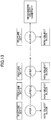
- Fig. 13 is a diagram illustrating an example for schematically explaining an object identification device included in the object candidate region recognition unit 24.
- the object identification device is configured by connecting plural identification devices serially for each layer.
- a feature set of one or more Haar-like features which is obtained by the learning is set in each layer.
- a block determined to be a vehicle or a pedestrian in the layer 1 is output to a block 2
- a block determined to be a vehicle or a pedestrian in the layer 2 is output to a block 3.
- Each layer has an evaluation function shown by expression (2).
- an output value of the evaluation function is smaller than a threshold set in advance, it is determined that it is not an object and an evaluation for the block is aborted.
- the size of a block extracted from an image is greater in an earlier layer.
- normalization of the size of block is performed (or a size of the Haar-like feature may be normalized), and a processing time for a large block is the same as a processing time for a small block.
- the number of blocks detected as large blocks is small and the number of blocks detected as small blocks is large. Therefore, when selected from large blocks, by recognizing that no object is included in the block, recognition processing for the block in further layers becomes unnecessary, and time required for recognizing an object (time for processing one image) can be shortened.
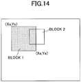
- Fig. 14 is a diagram illustrating an example for schematically explaining detection of a block and recognition of an object.
- the object candidate region recognition unit 24, as shown in Fig. 14 cuts out a rectangular block 1 from an image.
- a position and a size of the block in the image are defined by upper left coordinates (Xs, Ys) and lower right coordinates (Xe, Ye).
- Xs, Ys upper left coordinates
- Xe, Ye lower right coordinates
- the HOG feature is a brightness inclination histogram for each block in an image.
- a block of a part of the image is divided into cells with a predetermined number of pixels, an edge in a cell is detected, and an inclination of the edge is classified into any of nine directions, for example.
- a histogram of brightness inclination is created and normalized for each block.
- the normalized brightness inclination histogram is the HOG feature.
- the object candidate region recognition 24 calculates HOG features from the prepared positive teacher value and the negative teacher value, as in the case of the Haar-like features.
- An identification device for the HOG features is a brightness inclination histogram created from an image of a vehicle or a pedestrian. Similarity between histograms is calculated using Euclidean distances or Bhattacharyya distances. Positive teacher data are determined to be a correct answer when the similarity is greater than or equal to a threshold, and Negative teacher data are determined to be a correct answer when the similarity is less than the threshold.
- weights ⁇ t are set in the identification device and the weights can be determined by learning the teacher data by the Boosting.
- Fig. 15A is a diagram illustrating an example of a result of recognition for the object candidate region 103 in an image.
- Fig. 15B is a diagram illustrating an example of positions of the respective object candidate regions A to F in the image. It is found that in each of the object candidate regions A, C, E and D a vehicle is imaged. On the contrary, in any of the object candidate regions B and F a vehicle is not imaged, and is regarded as a false recognition in the present circumstances. However, as described later, by the object recognition processing unit 26 taking account of the position relative to the road surface region 101, the object candidate regions B, F will be excluded.
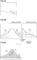
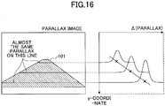
- Fig. 16 is a diagram illustrating an example for schematically explaining the detection of the road surface region 101 according to the invention.
- the road is assumed to be flat for explanation.
- a left part of Fig. 16 illustrates schematically the road surface region 101 in a parallax image, and a right part of Fig. 16 illustrates a parallax histogram.
- the parallax histogram is a histogram of a parallax value ⁇ of one horizontal line in the parallax image. Since the road surface region 101 is flat, the parallax value ⁇ of one line in the horizontal direction is almost constant. Therefore, in the case where the road surface region 101 exists, the histogram of the parallax value ⁇ of one line in the horizontal direction concentrates on this constant parallax value ⁇ , and has a peak at the parallax value ⁇ .
- the histogram of the parallax value of one line in the horizontal direction in the parallax image is plotted with respect to y-coordinate (vertical direction of the image).
- the parallax value ⁇ becomes gradually smaller, as it goes to a distance (in the direction where y-coordinate decreases).
- a length of the road surface region 101 in the horizontal direction becomes gradually shorter. Therefore, as shown in the right part of Fig. 16 , the peak of the histogram becomes gradually smaller and moves gradually in the upper left direction as it goes to a distance.
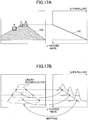
- Fig. 17A is a diagram illustrating an example of a road inclination curve 107 obtained from the peaks of the histograms.
- the road inclination curve 107 is a straight line.
- the Hough transformation is known.
- an approximated line is found by using a least square method and a correlation coefficient exhibits a value sufficiently close to a line (for example, greater than or equal to 0.9 where the maximum is 1.0), it may be determined that a line is detected.
- the road surface detection processing unit 25 identifies a pixel of a parallax value, at which the histogram has a peak, on the parallax image. That is, the parallax value at which the histogram has a peak is associated with a parallax value on the parallax image (mapping).
- Fig. 17B is a diagram illustrating an example for explaining the mapping.
- the parallax value of peak on the line in the histogram diagram and a pixel on the parallax image having the same parallax value are identified.
- a pixel region in the parallax image associated with the parallax value of peak is the road surface region 101.
- the road surface detection processing unit 25 performs an interpolation process between points to create the road surface region 101. That is, since a horizontal line between a leftmost end and a rightmost end which are mapped at an arbitrary y-coordinate is supposed to be the road surface region, an interpolation process is performed in the horizontal direction. Moreover, at respective y-coordinates, leftmost points on the road surface region may be approximated by a line and rightmost points may be approximated by a line. According to the above, the road surface region 101 with outer edges having straight line shapes can be determined.
- the road surface region 101 can be detected to the extent that there is not a significant disadvantage for driving support.
- the number of approximate curves is large, a length of one line is small and accuracy in the approximation with lines is low. That is, in the case of detecting a short line by the Hough transformation, accuracy in the detection of the line is low.
- the image processing apparatus 100 determines the number of lines according to a slope detected by the laser radar range finding unit 28.
- Fig. 19A is a diagram illustrating an example for explaining the detection of slope by the laser radar range finding unit 28.
- laser light is scanned in the vertical direction.
- the laser lights emitted in the directions A, B and C according to the scanning are reflected on the road surface and received by the light reception unit 920. It is determined that the laser light recognizes the road surface, since a position the laser light reaches is not the object candidate region 103. That is, in the case where laser light is reflected from three directions A, B and C, according to whether the object candidate region 103 exists in each of the direction and at its distance, it is determined whether it is a road surface.
- the road surface detection processing unit 25 determines a slope based on the reflected light from the farthest (direction of the highest elevation angle). Therefore, the road region to a remote spot can be detected.
- the slope angle ⁇ is an elevation angle of the reflection direction, as shown in Fig. 19B .
- the slope may be determined according to a difference between heights of the point C and of the point O.
- the height h is calculated by L ⁇ sin ⁇
- the distance M in the horizontal direction between the point C and the point O is calculated by L ⁇ cos ⁇ . Accordingly, the slope can be obtained only from the orientation (slope), or the distance and the orientation (slope).
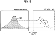
- the road surface detection processing unit 25 increases the number of approximate lines as the slope becomes greater, and decreases the number of approximate lines as the slope becomes smaller.
- the slope is great, as shown by the road inclination curve 107 in the right part of Fig. 18 , a curvature becomes greater and the approximation is improved if it is approximated using a large number of lines for the approximation with lines.
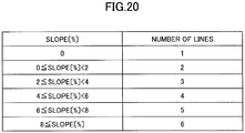
- Fig. 20 is a diagram illustrating an example of a table in which the slope angle is associated with the number of approximate curves.
- the table is stored in the flash ROM 113 or the RAM 112 in the image processing apparatus 100.
- the table may be stored in a server which can be accessed via a network.
- the slope angle (%) is obtained by 100 ⁇ (change in height)/(travel distance). Moreover, the slope angle (%) is an absolute value, and deals with both an ascending road and a descending road. For the slope of 0%, the number of approximate curves is one. The number of approximate curves increases as the slope angle becomes greater.
- the road surface detection processing unit 25 calculates the slope angle (%) based on an orientation (slope) or a distance and an orientation (slope) acquired from the laser radar range finding unit 28, and determines the number of approximate curves with reference to the table.
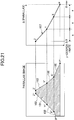
- Fig. 21 is a diagram illustrating an example for explaining the detection of the road surface region 101 when the road surface is slanted.
- the road surface detection processing unit 25 acquires the orientation (slope) or the distance and the orientation (slope) from the laser radar range finding unit 28. Then, the number of approximate curves is determined from the table. Here, it is assumed that the number is determined to be three.
- the road surface detection processing unit 25 divides the length between the maximum parallax value ⁇ max having a peak and the minimum parallax value ⁇ 0 having a peak equally among three segments each having a length "a”. Then, from points P, X, Y and Z which are identified by these parallax values ( ⁇ 0 to ⁇ max), lines are detected. That is, the Hough transformation is performed for peaks of histograms between P and X, peaks between X and Y and peaks between Y and Z, respectively. By determining the approximate number of lines in this way, the road inclination curve 107 can be approximated with lines, the number of which is not too large and not too small.
- the road surface detection processing unit 25 in the same way as in the case of the flat road surface, detects the road surface region 101 by identifying a pixel of the parallax image corresponding to the parallax value of the peak of the histogram. Moreover, since it is identified by a line from left and right outer edges of the road surface region 101, the road surface detection processing unit 25 approximates the left and right outer edges of the road surface region 101 with lines, the number of which is the same as that for the road inclination curve 107. That is, a segment of the right outer edge of the road surface region 101 between P' corresponding to P and X' corresponding to X is approximated by a line.
- a segment between X' and Y' corresponding to Y and a segment between Y' and Z' corresponding to Z are approximated by lines, respectively.
- the points P', X', Y' and Z' are points of pixels at rightmost edge having the same parallax value as the parallax value of the peaks.
- the left outer edge is approximated with lines in the same way as above.
- the points P", X", Y" and Z" are points of pixels at leftmost edge having the same parallax value as the parallax value of the peaks. Accordingly, even when the road surface is inclined, the road surface region 101 can be determined accurately.
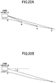
- Fig. 22A is a diagram illustrating an example for explaining the detection of the slope by the laser radar range finding unit 28.
- the laser lights emitted in the directions A, B and C are reflected on the road surface and received by the light reception unit 920.
- the road surface detection processing unit 25 determines the slope based on the reflected light from the direction an elevation angle of which is the closest to the horizontal direction (the farthest).
- the slope angle ⁇ is an elevation angle of the reflection direction, as shown in Fig. 22B .
- the slope may be determined according to a difference between heights of the point C and of the point O.
- Fig. 23 is a diagram illustrating an example for explaining the detection of the road surface region 101 when the road surface is slanted. Also in the case of the descending road, the peaks of the histograms are not placed on a straight line. This is because when y-coordinate becomes smaller, the road surface is seen distantly since the road surface is slanted, and the position of the peak is shifted in a direction where the parallax value ⁇ decreases.
- the road surface detection processing unit 25 determines the number of approximate curves from the table. Further processing is the same as in the case of the ascending road.
- the determination whether the road surface is slanted will be explained. Since the road surface detection processing unit 25 creates a road inclination curve 107 with a line when the vehicle travels on a road which is not slanted, the road surface detection processing unit 25 determines whether to increase a number of the lines according to a result of determination whether there is a slope.
- the method of determination includes a method using a line detected by the Hough transformation and a method using an orientation (slope) detected by the laser radar range finding unit 28.
- a line can be detected by the Hough transformation. Since it is detected that there is a slope before detecting the road surface region 101, the road surface detection processing unit 25 monitors a slope of the road inclination curve 107. In the case where the road is flat, since the y-coordinate of a vanishing point is constant, the slope of the road inclination curve 107 is a prescribed value. On the other hand, in the case of an ascending road, the vanishing point rises higher (y-coordinate becomes smaller). In the case of a descending road, the vanishing point moves lower (y-coordinate becomes greater). Moreover, when the vanishing point moves vertically, the slope of the road inclination curve 107 changes.
- the road surface detection processing unit 25 determines that there is an ascending road in the case where the vanishing point (y-coordinate when the parallax value is zero) of the road inclination curve 107 is significantly higher than the vanishing point in the case of the flat road. Moreover, the road surface detection processing unit 25 determines that there is a descending road in the case where the vanishing point of the road inclination curve 107 is significantly lower than the vanishing point in the case of the flat road.
- an object is detected from an orientation other than the horizontal direction.
- an object candidate region 103 in the direction it is determined that the road is slanted.
- Fig. 24 is a flowchart illustrating an example of a procedure of recognizing an object in the image processing apparatus 100 according to the present embodiment.
- the stereo image input unit 21 outputs the stereo images to the brightness image input unit 22 and the parallax image calculation unit 23 (step S10).
- the brightness image input unit 22 inputs either of left and right brightness images to the object candidate region recognition unit 24 (step S40).
- the parallax image calculation unit 23 calculates a parallax image (step S20).
- the object candidate region recognition unit 24 recognizes an object candidate region 103 from the brightness image or a parallax image (step S30).
- the road surface detection processing unit 25 detects a road surface region 101 (step S50).
- the range finding information acquisition unit 29 acquires object information from the laser radar range finding unit 28 (step S60). According to the above operation, a road inclination curve 107 and the road surface region 101 can be approximated by plural lines, and the road surface region 101 can be detected accurately.
- the object recognition processing unit 26 performs object recognition processing (step S70). That is, the object candidate region 103, at least a part of which overlaps the road surface region 101 is detected as an object region.
- the object recognition result processing unit outputs a result of object recognition to the ECU 98 (step S80).
- the image processing apparatus 100 by combining distance images picked up by a stereo camera and a laser radar, can detect the road surface region 101 with high accuracy and recognize an object with high accuracy.
- the stereo camera 99 is installed so as to image an object in front of the vehicle.
- the camera may be installed so that it can image not only the front but also the rear, the rear side or the like.
- the recognition of only a vehicle or a pedestrian is explained.
- the image processing apparatus 100 can recognize a bicycle, a motorcycle or the like.
- the image processing apparatus may be installed on not only a car having four wheels but also a three-wheeled automobile, a heavy vehicle having more than four wheels or the like. Moreover, the image processing apparatus may be installed on a motorcycle.
Landscapes
- Engineering & Computer Science (AREA)
- Physics & Mathematics (AREA)
- General Physics & Mathematics (AREA)
- Multimedia (AREA)
- Electromagnetism (AREA)
- Radar, Positioning & Navigation (AREA)
- Remote Sensing (AREA)
- Computer Networks & Wireless Communication (AREA)
- Signal Processing (AREA)
- Theoretical Computer Science (AREA)
- Computer Vision & Pattern Recognition (AREA)
- Traffic Control Systems (AREA)
- Optical Radar Systems And Details Thereof (AREA)
- Image Analysis (AREA)
- Measurement Of Optical Distance (AREA)
- Image Processing (AREA)
Claims (11)
- Ein Bildverarbeitungsgerät (100) zum Detektieren einer Bildregion in einem von einer Stereokamera (99) aufgenommenen Bild, aufweisend:eine Abstandsakquirierungseinheit, die dazu eingerichtet ist, von einer Lasar-Radar-Abstandsermittlungseinheit (28) eine Vielzahl von Abständen zwischen der Stereokamera (99) und Positionen, an denen elektromagnetische Wellen, emittiert in Richtungen um eine optische Achse der Stereokamera (99), reflektiert werden, zu akquirieren;eine Parallaxenbild-Berechnungseinheit (23), die dazu eingerichtet ist, ein Parallaxenbild zu erzeugen, das einen Parallaxenwert für jeden Pixel oder jeden Pixelblock in dem von der Stereokamera (99) aufgenommenen Bild enthält; undeine Bildregion-Ermittlungseinheit (24), die dazu eingerichtet ist, ein Histogramm der Parallaxenwerte für jede horizontale Linie in dem Parallaxenbild zu erzeugen,wobei die Bildregion-Ermittlungseinheit (24) dazu eingerichtet ist, eine Neigung der Bildregion zu bestimmen gemäß dem Abstand erhalten von der reflektierten Welle der elektromagnetischen Welle, die in die Richtung mit einem größten Erhebungswinkel mit Bezug auf auf die optische Achse der Stereokamera (99) emittiert ist, und die Bildregion zu bestimmen durch das Detektieren von Linien aus einer Punktwolke, in der Parallaxenwerte, bei denen die Histogramme Spitzen haben, gezeichnet sind mit Bezug auf eine Höhe in dem Parallaxenbild, wobei eine Anzahl der Linien basierend auf der Neigung festgelegt wird.
- Das Bilderarbeitungsgerät (100) wie im Anspruch 1 beansprucht, wobei die Bildregion-Ermittlungseinheit (24) dazu eingerichtet ist, eine größere Anzahl von Linien für eine größere Neigung zu detektieren.
- Das Bilderarbeitungsgerät (100) wie im Anspruch 1 oder 2 beansprucht, wobei die Bildregion-Ermittlungseinheit (24) dazu eingerichtet ist, eine Bildregion zu ermitteln, die den Pixel in dem Parallaxenbild enthält, der den Parallaxenwert hat, bei dem das Histogramm eine Spitze hat, und einen äußeren Rand der Bildregion zu approximieren durch Linien für jeden von Teilen der Bildregion angeordnet in der Höhenrichtung des Parallaxenbildes.
- Das Bilderarbeitungsgerät (100) wie in einem der Ansprüche 1 oder 3 beansprucht, weiter aufweisend:eine Detektionsziel-Kandidatenregion-Detektionseinheit (24), die dazu eingerichtet ist, Detektionsziel-Kandidatenregionen in dem Bild zu detektieren; undeine Detektionszielregion-Detektionseinheit (24), die dazu eingerichtet ist, aus den Detektionsziel-Kandidatenregionen eine Detektionszielregion zu detektieren, in der ein Detektionsziel abgebildet ist, basierend auf Positionsbeziehungen zwischen den Detektionsziel-Kandidatenregionen und der Bildregion.
- Das Bildverarbeitungsgerät (100) wie im Anspruch 4 beansprucht, wobei die Detektionszielregion-Detektionseinheit (24) dazu eingerichtet ist, die Detektionszielregion zu detektieren in einem Fall, in dem zumindest ein Teil der Detektionszielregion mit der Bildregion überlappt.
- Das Bilderarbeitungsgerät (100) wie in einem der Ansprüche 1 oder 5 beansprucht, wobei die Bildregion ein Bild einer Straßenoberfläche enthält.
- Ein Bildverarbeitungsverfahren zum Detektieren einer Bildregion in einem von einer Stereokamera (99) aufgenommenen Bild, aufweisend:das Akquirieren einer Vielzahl von Abständen zwischen der Stereokamera (99) und Positionen, an denen elektromagnetische Wellen, emittiert in Richtungen um eine optische Achse der Stereokamera (99), reflektiert werden;das Erzeugen eines Parallaxenbildes, das einen Parallaxenwert für jeden Pixel oder jeden Pixelblock in dem von der Stereokamera (99) aufgenommenen Bild enthält; unddas Erzeugen eines Histogramms der Parallaxenwerte für jede horizontale Linie in dem Parallaxenbild,das Bestimmen einer Neigung der Bildregion gemäß dem Abstand erhalten von der reflektierten Welle der elektromagnetischen Welle, die in die Richtung mit einem größten Erhebungswinkel mit Bezug auf auf die optische Achse der Stereokamera (99) emittiert ist; unddas Bestimmen der Bildregion durch das Detektieren von Linien aus einer Punktwolke, in der Parallaxenwerte, bei denen die Histogramme Spitzen haben, gezeichnet sind mit Bezug auf eine Höhe in dem Parallaxenbild, wobei eine Anzahl der Linien basierend auf der Neigung festgelegt wird.
- Ein Computerprogramm enthaltend Instruktionen die, wenn das Programm von einem Computer ausgeführt wird, den Computer dazu veranlassen, das Verfahren nach Anspruch 7 auszuführen.
- Ein Bildverarbeitungssystem (200) zum Detektieren einer Bildregion in einem von einer Stereokamera (99) aufgenommenen Bild und zum Detektieren eines Detektionsziels basierend auf der Bildregion, enthaltend:eine Lasar-Radar-Abstandsermittlungseinheit (28), die dazu eingerichtet ist, die elektromagnetischen Wellen zu emittieren; undein Bildverabeitungsgerät (100) nach einem der Ansprüche 1 bis 6.
- Das Bildverarbeitungssystem (200) wie im Anspruch 9 beansprucht, weiter aufweisend:
eine Fahrunterstützungseinheit, die dazu eingerichtet ist, eine Fahrunterstützung für einen Fahrer eines beweglichen Körpers durchzuführen basierend auf dem Abstand für die Detektionszielregion, wobei das Bildverarbeitungssystem (200) in dem beweglichen Körper installierbar ist. - Das Bildverarbeitungssystem (200) wie in einem der Ansprüche 9 oder beansprucht, wobei die Lasar-Radar-Abstandsermittlungseinheit (28) dazu eingerichtet ist, die Neigung der Bildregion zu ermitteln, in einem Fall, in dem ein Parameter der detektierten Linie größer ist als ein Grenzwert, und die Bildregion-Ermittlungseinheit (24) dazu eingerichtet ist, die Bildregion basierend auf der Neigung zu ermitteln.
Applications Claiming Priority (2)
| Application Number | Priority Date | Filing Date | Title |
|---|---|---|---|
| JP2013272524 | 2013-12-27 | ||
| JP2014256892A JP6540009B2 (ja) | 2013-12-27 | 2014-12-19 | 画像処理装置、画像処理方法、プログラム、画像処理システム |
Publications (2)
| Publication Number | Publication Date |
|---|---|
| EP2889641A1 EP2889641A1 (de) | 2015-07-01 |
| EP2889641B1 true EP2889641B1 (de) | 2021-06-02 |
Family
ID=52391754
Family Applications (1)
| Application Number | Title | Priority Date | Filing Date |
|---|---|---|---|
| EP14200098.3A Active EP2889641B1 (de) | 2013-12-27 | 2014-12-23 | Bildverarbeitungsvorrichtung, Bildverarbeitungsverfahren, Programm und Bildverarbeitungssystem |
Country Status (2)
| Country | Link |
|---|---|
| EP (1) | EP2889641B1 (de) |
| JP (1) | JP6540009B2 (de) |
Families Citing this family (25)
| Publication number | Priority date | Publication date | Assignee | Title |
|---|---|---|---|---|
| JP6365385B2 (ja) * | 2015-04-17 | 2018-08-01 | トヨタ自動車株式会社 | 立体物検出装置及び立体物検出方法 |
| WO2017057056A1 (ja) | 2015-09-30 | 2017-04-06 | ソニー株式会社 | 情報処理装置、情報処理方法、及び、プログラム |
| EP3358551B1 (de) * | 2015-09-30 | 2021-10-27 | Sony Group Corporation | Informationsverarbeitungsvorrichtung, informationsverarbeitungsverfahren und programm |
| JP2017101944A (ja) * | 2015-11-30 | 2017-06-08 | パイオニア株式会社 | 速度算出装置、制御方法、プログラム及び記憶媒体 |
| EP3508861B1 (de) | 2016-09-02 | 2023-01-11 | Pioneer Corporation | Geschwindigkeitsberechnungsvorrichtung, steuerungsverfahren, programm und speichermedium |
| JP6828332B2 (ja) * | 2016-09-12 | 2021-02-10 | 株式会社リコー | 画像処理装置、物体認識装置、機器制御システム、画像処理方法およびプログラム |
| JP2018092596A (ja) * | 2016-11-30 | 2018-06-14 | 株式会社リコー | 情報処理装置、撮像装置、機器制御システム、移動体、情報処理方法、およびプログラム |
| CN108629805B (zh) * | 2017-03-15 | 2021-12-14 | 纵目科技(上海)股份有限公司 | 一种基于图像分层技术的显著性物体检测方法及系统 |
| JP6782433B2 (ja) * | 2017-03-22 | 2020-11-11 | パナソニックIpマネジメント株式会社 | 画像認識装置 |
| JP2019095267A (ja) * | 2017-11-21 | 2019-06-20 | 株式会社ダイヘン | 出力装置、位置計測システム、プログラム及び固定局の位置の座標の計測方法 |
| JP7167431B2 (ja) * | 2017-11-21 | 2022-11-09 | 株式会社デンソー | 勾配変化検出装置、方法及びプログラム、並びに、車両 |
| JP2019138630A (ja) | 2018-02-06 | 2019-08-22 | オムロンオートモーティブエレクトロニクス株式会社 | 対象物検出装置 |
| WO2019244334A1 (ja) | 2018-06-22 | 2019-12-26 | 三菱電機株式会社 | センサ制御装置、車両、センシング方法およびセンサ制御プログラム |
| JP7082545B2 (ja) * | 2018-08-01 | 2022-06-08 | パナソニック インテレクチュアル プロパティ コーポレーション オブ アメリカ | 情報処理方法、情報処理装置およびプログラム |
| CN109559356B (zh) * | 2018-12-26 | 2022-09-16 | 长安大学 | 一种基于机器视觉的高速公路视距检测方法 |
| CN111366164B (zh) * | 2018-12-26 | 2023-12-29 | 华为技术有限公司 | 定位方法及电子设备 |
| US12054162B2 (en) | 2019-04-05 | 2024-08-06 | Volvo Truck Corporation | Method and a control unit for determining a parameter indicative of a road capability of a road segment supporting a vehicle |
| KR102921223B1 (ko) | 2019-05-17 | 2026-02-02 | 삼성전자주식회사 | 첨단 운전자 지원 장치 및 이의 객체를 검출하는 방법 |
| CN111079611B (zh) * | 2019-12-09 | 2021-03-30 | 成都奥伦达科技有限公司 | 一种道路面及其标志线的自动提取方法 |
| US11391842B2 (en) * | 2020-01-06 | 2022-07-19 | Luminar, Llc | Adaptive scan pattern with virtual horizon estimation |
| JP2023089311A (ja) * | 2020-04-22 | 2023-06-28 | ソニーセミコンダクタソリューションズ株式会社 | 情報処理装置、撮像システム、情報処理方法及びコンピュータプログラム |
| CN113673282B (zh) * | 2020-05-14 | 2025-08-19 | 深圳引望智能技术有限公司 | 目标检测方法和装置 |
| US12304503B2 (en) | 2020-09-16 | 2025-05-20 | Hitachi Astemo, Ltd. | Vehicle orientation estimation system and vehicle orientation estimation method |
| JP2024074680A (ja) * | 2022-11-21 | 2024-05-31 | 株式会社シマノ | 人力駆動車用の制御方法、および、人力駆動車用の制御装置 |
| KR102927474B1 (ko) | 2023-05-31 | 2026-02-13 | 주식회사 씨에스 | 스테레오 카메라와 레이저를 이용한 해충 퇴치 장치 |
Citations (1)
| Publication number | Priority date | Publication date | Assignee | Title |
|---|---|---|---|---|
| JP2012225806A (ja) * | 2011-04-20 | 2012-11-15 | Toyota Central R&D Labs Inc | 道路勾配推定装置及びプログラム |
Family Cites Families (8)
| Publication number | Priority date | Publication date | Assignee | Title |
|---|---|---|---|---|
| JP3212218B2 (ja) * | 1994-05-26 | 2001-09-25 | 三菱電機株式会社 | 車両用障害物検出装置 |
| JP3669205B2 (ja) | 1999-05-17 | 2005-07-06 | 日産自動車株式会社 | 障害物認識装置 |
| JP4311861B2 (ja) * | 2000-05-18 | 2009-08-12 | 富士通テン株式会社 | 車両用物体検出装置 |
| JP4032843B2 (ja) | 2002-06-25 | 2008-01-16 | 富士重工業株式会社 | 監視システムおよび監視方法、当該監視システムにおける距離補正装置および距離補正方法 |
| JP4193886B2 (ja) * | 2006-07-26 | 2008-12-10 | トヨタ自動車株式会社 | 画像表示装置 |
| KR20130051681A (ko) * | 2011-11-10 | 2013-05-21 | 한국전자통신연구원 | 노면 표식물 인식 시스템 및 방법 |
| JP2014006882A (ja) * | 2012-05-31 | 2014-01-16 | Ricoh Co Ltd | 路面傾斜認識装置、路面傾斜認識方法及び路面傾斜認識用プログラム |
| EP2669845A3 (de) * | 2012-06-01 | 2014-11-19 | Ricoh Company, Ltd. | Zielerkennungssystem, vom Zielerkennungssystem durchgeführtes Zielerkennungsverfahren, auf dem Zielerkennungssystem ausgeführtes Zielerkennungsprogramm und Aufzeichnungsmedium mit darauf gespeichertem Zielerkennungsprogramm |
-
2014
- 2014-12-19 JP JP2014256892A patent/JP6540009B2/ja active Active
- 2014-12-23 EP EP14200098.3A patent/EP2889641B1/de active Active
Patent Citations (1)
| Publication number | Priority date | Publication date | Assignee | Title |
|---|---|---|---|---|
| JP2012225806A (ja) * | 2011-04-20 | 2012-11-15 | Toyota Central R&D Labs Inc | 道路勾配推定装置及びプログラム |
Also Published As
| Publication number | Publication date |
|---|---|
| EP2889641A1 (de) | 2015-07-01 |
| JP6540009B2 (ja) | 2019-07-10 |
| JP2015143979A (ja) | 2015-08-06 |
Similar Documents
| Publication | Publication Date | Title |
|---|---|---|
| EP2889641B1 (de) | Bildverarbeitungsvorrichtung, Bildverarbeitungsverfahren, Programm und Bildverarbeitungssystem | |
| JP6795027B2 (ja) | 情報処理装置、物体認識装置、機器制御システム、移動体、画像処理方法およびプログラム | |
| KR102772870B1 (ko) | 전자기기 및 제어방법 | |
| EP3229041B1 (de) | Objekterfassung mittels radar- und sichtdefiniertem bilderfassungsbereich | |
| JP5690688B2 (ja) | 外界認識方法,装置,および車両システム | |
| JP6459659B2 (ja) | 画像処理装置、画像処理方法、運転支援システム、プログラム | |
| US10074021B2 (en) | Object detection apparatus, object detection method, and program | |
| CN110431562B (zh) | 图像识别装置 | |
| US9286523B2 (en) | Line recognition apparatus, line recognition method and line recognition program storage medium | |
| US10832431B2 (en) | Image processing apparatus, object recognition apparatus, equipment control system, image processing method, and computer-readable recording medium | |
| US8977006B2 (en) | Target recognition system and target recognition method executed by the target recognition system | |
| US20050232463A1 (en) | Method and apparatus for detecting a presence prior to collision | |
| US20200074212A1 (en) | Information processing device, imaging device, equipment control system, mobile object, information processing method, and computer-readable recording medium | |
| US10672141B2 (en) | Device, method, system and computer-readable medium for determining collision target object rejection | |
| US20140347484A1 (en) | Apparatus and method for providing surrounding environment information of vehicle | |
| JP6743882B2 (ja) | 画像処理装置、機器制御システム、撮像装置、画像処理方法及びプログラム | |
| US20190001910A1 (en) | Image processing apparatus, imaging device, moving body device control system, image processing method, and program product | |
| US20180285661A1 (en) | Image processing device, object recognizing device, device control system, image processing method, and computer-readable medium | |
| US20210286082A1 (en) | Distance measuring device and distance measuring device control method | |
| US11054245B2 (en) | Image processing apparatus, device control system, imaging apparatus, image processing method, and recording medium | |
| US10546383B2 (en) | Image processing device, object recognizing device, device control system, image processing method, and computer-readable medium | |
| JP6733302B2 (ja) | 画像処理装置、撮像装置、移動体機器制御システム、画像処理方法、及びプログラム | |
| EP3540643A1 (de) | Bildverarbeitungsvorrichtung und bildverarbeitungsverfahren | |
| JP6943092B2 (ja) | 情報処理装置、撮像装置、機器制御システム、移動体、情報処理方法、及び、情報処理プログラム | |
| KR20220089788A (ko) | 차량용 카메라를 이용한 주차보조 방법 및 장치 |
Legal Events
| Date | Code | Title | Description |
|---|---|---|---|
| PUAI | Public reference made under article 153(3) epc to a published international application that has entered the european phase |
Free format text: ORIGINAL CODE: 0009012 |
|
| 17P | Request for examination filed |
Effective date: 20141223 |
|
| AK | Designated contracting states |
Kind code of ref document: A1 Designated state(s): AL AT BE BG CH CY CZ DE DK EE ES FI FR GB GR HR HU IE IS IT LI LT LU LV MC MK MT NL NO PL PT RO RS SE SI SK SM TR |
|
| AX | Request for extension of the european patent |
Extension state: BA ME |
|
| STAA | Information on the status of an ep patent application or granted ep patent |
Free format text: STATUS: EXAMINATION IS IN PROGRESS |
|
| 17Q | First examination report despatched |
Effective date: 20190319 |
|
| REG | Reference to a national code |
Ref country code: DE Ref legal event code: R079 Ref document number: 602014077851 Country of ref document: DE Free format text: PREVIOUS MAIN CLASS: G01S0017020000 Ipc: G01S0017420000 |
|
| RIC1 | Information provided on ipc code assigned before grant |
Ipc: G06K 9/00 20060101ALI20201202BHEP Ipc: H04N 13/00 20180101ALN20201202BHEP Ipc: G01S 17/42 20060101AFI20201202BHEP Ipc: H04N 13/271 20180101ALI20201202BHEP Ipc: G06T 7/12 20170101ALI20201202BHEP Ipc: H04N 13/239 20180101ALI20201202BHEP Ipc: G01S 17/931 20200101ALI20201202BHEP Ipc: G01S 17/86 20200101ALI20201202BHEP |
|
| GRAP | Despatch of communication of intention to grant a patent |
Free format text: ORIGINAL CODE: EPIDOSNIGR1 |
|
| STAA | Information on the status of an ep patent application or granted ep patent |
Free format text: STATUS: GRANT OF PATENT IS INTENDED |
|
| INTG | Intention to grant announced |
Effective date: 20210115 |
|
| RIN1 | Information on inventor provided before grant (corrected) |
Inventor name: SUZUKI, SHUICHI Inventor name: FUJIMOTO, HIDEOMI Inventor name: GUAN, HAIKE Inventor name: SEKIGUCHI, HIROYOSHI Inventor name: AOKI, SHIN Inventor name: NAKAJIMA, MITSURU Inventor name: YOKOTA, SOICHIRO Inventor name: YOSHIDA, JUN |
|
| GRAS | Grant fee paid |
Free format text: ORIGINAL CODE: EPIDOSNIGR3 |
|
| GRAA | (expected) grant |
Free format text: ORIGINAL CODE: 0009210 |
|
| STAA | Information on the status of an ep patent application or granted ep patent |
Free format text: STATUS: THE PATENT HAS BEEN GRANTED |
|
| REG | Reference to a national code |
Ref country code: CH Ref legal event code: EP |
|
| AK | Designated contracting states |
Kind code of ref document: B1 Designated state(s): AL AT BE BG CH CY CZ DE DK EE ES FI FR GB GR HR HU IE IS IT LI LT LU LV MC MK MT NL NO PL PT RO RS SE SI SK SM TR |
|
| REG | Reference to a national code |
Ref country code: GB Ref legal event code: FG4D |
|
| REG | Reference to a national code |
Ref country code: AT Ref legal event code: REF Ref document number: 1398979 Country of ref document: AT Kind code of ref document: T Effective date: 20210615 |
|
| REG | Reference to a national code |
Ref country code: IE Ref legal event code: FG4D |
|
| REG | Reference to a national code |
Ref country code: DE Ref legal event code: R096 Ref document number: 602014077851 Country of ref document: DE |
|
| REG | Reference to a national code |
Ref country code: LT Ref legal event code: MG9D |
|
| PG25 | Lapsed in a contracting state [announced via postgrant information from national office to epo] |
Ref country code: HR Free format text: LAPSE BECAUSE OF FAILURE TO SUBMIT A TRANSLATION OF THE DESCRIPTION OR TO PAY THE FEE WITHIN THE PRESCRIBED TIME-LIMIT Effective date: 20210602 Ref country code: LT Free format text: LAPSE BECAUSE OF FAILURE TO SUBMIT A TRANSLATION OF THE DESCRIPTION OR TO PAY THE FEE WITHIN THE PRESCRIBED TIME-LIMIT Effective date: 20210602 Ref country code: FI Free format text: LAPSE BECAUSE OF FAILURE TO SUBMIT A TRANSLATION OF THE DESCRIPTION OR TO PAY THE FEE WITHIN THE PRESCRIBED TIME-LIMIT Effective date: 20210602 Ref country code: BG Free format text: LAPSE BECAUSE OF FAILURE TO SUBMIT A TRANSLATION OF THE DESCRIPTION OR TO PAY THE FEE WITHIN THE PRESCRIBED TIME-LIMIT Effective date: 20210902 |
|
| REG | Reference to a national code |
Ref country code: NL Ref legal event code: MP Effective date: 20210602 |
|
| REG | Reference to a national code |
Ref country code: AT Ref legal event code: MK05 Ref document number: 1398979 Country of ref document: AT Kind code of ref document: T Effective date: 20210602 |
|
| PG25 | Lapsed in a contracting state [announced via postgrant information from national office to epo] |
Ref country code: SE Free format text: LAPSE BECAUSE OF FAILURE TO SUBMIT A TRANSLATION OF THE DESCRIPTION OR TO PAY THE FEE WITHIN THE PRESCRIBED TIME-LIMIT Effective date: 20210602 Ref country code: RS Free format text: LAPSE BECAUSE OF FAILURE TO SUBMIT A TRANSLATION OF THE DESCRIPTION OR TO PAY THE FEE WITHIN THE PRESCRIBED TIME-LIMIT Effective date: 20210602 Ref country code: NO Free format text: LAPSE BECAUSE OF FAILURE TO SUBMIT A TRANSLATION OF THE DESCRIPTION OR TO PAY THE FEE WITHIN THE PRESCRIBED TIME-LIMIT Effective date: 20210902 Ref country code: PL Free format text: LAPSE BECAUSE OF FAILURE TO SUBMIT A TRANSLATION OF THE DESCRIPTION OR TO PAY THE FEE WITHIN THE PRESCRIBED TIME-LIMIT Effective date: 20210602 Ref country code: GR Free format text: LAPSE BECAUSE OF FAILURE TO SUBMIT A TRANSLATION OF THE DESCRIPTION OR TO PAY THE FEE WITHIN THE PRESCRIBED TIME-LIMIT Effective date: 20210903 Ref country code: LV Free format text: LAPSE BECAUSE OF FAILURE TO SUBMIT A TRANSLATION OF THE DESCRIPTION OR TO PAY THE FEE WITHIN THE PRESCRIBED TIME-LIMIT Effective date: 20210602 |
|
| PG25 | Lapsed in a contracting state [announced via postgrant information from national office to epo] |
Ref country code: SM Free format text: LAPSE BECAUSE OF FAILURE TO SUBMIT A TRANSLATION OF THE DESCRIPTION OR TO PAY THE FEE WITHIN THE PRESCRIBED TIME-LIMIT Effective date: 20210602 Ref country code: SK Free format text: LAPSE BECAUSE OF FAILURE TO SUBMIT A TRANSLATION OF THE DESCRIPTION OR TO PAY THE FEE WITHIN THE PRESCRIBED TIME-LIMIT Effective date: 20210602 Ref country code: EE Free format text: LAPSE BECAUSE OF FAILURE TO SUBMIT A TRANSLATION OF THE DESCRIPTION OR TO PAY THE FEE WITHIN THE PRESCRIBED TIME-LIMIT Effective date: 20210602 Ref country code: CZ Free format text: LAPSE BECAUSE OF FAILURE TO SUBMIT A TRANSLATION OF THE DESCRIPTION OR TO PAY THE FEE WITHIN THE PRESCRIBED TIME-LIMIT Effective date: 20210602 Ref country code: RO Free format text: LAPSE BECAUSE OF FAILURE TO SUBMIT A TRANSLATION OF THE DESCRIPTION OR TO PAY THE FEE WITHIN THE PRESCRIBED TIME-LIMIT Effective date: 20210602 Ref country code: PT Free format text: LAPSE BECAUSE OF FAILURE TO SUBMIT A TRANSLATION OF THE DESCRIPTION OR TO PAY THE FEE WITHIN THE PRESCRIBED TIME-LIMIT Effective date: 20211004 Ref country code: NL Free format text: LAPSE BECAUSE OF FAILURE TO SUBMIT A TRANSLATION OF THE DESCRIPTION OR TO PAY THE FEE WITHIN THE PRESCRIBED TIME-LIMIT Effective date: 20210602 Ref country code: ES Free format text: LAPSE BECAUSE OF FAILURE TO SUBMIT A TRANSLATION OF THE DESCRIPTION OR TO PAY THE FEE WITHIN THE PRESCRIBED TIME-LIMIT Effective date: 20210602 Ref country code: AT Free format text: LAPSE BECAUSE OF FAILURE TO SUBMIT A TRANSLATION OF THE DESCRIPTION OR TO PAY THE FEE WITHIN THE PRESCRIBED TIME-LIMIT Effective date: 20210602 |
|
| REG | Reference to a national code |
Ref country code: DE Ref legal event code: R097 Ref document number: 602014077851 Country of ref document: DE |
|
| PLBE | No opposition filed within time limit |
Free format text: ORIGINAL CODE: 0009261 |
|
| STAA | Information on the status of an ep patent application or granted ep patent |
Free format text: STATUS: NO OPPOSITION FILED WITHIN TIME LIMIT |
|
| PG25 | Lapsed in a contracting state [announced via postgrant information from national office to epo] |
Ref country code: DK Free format text: LAPSE BECAUSE OF FAILURE TO SUBMIT A TRANSLATION OF THE DESCRIPTION OR TO PAY THE FEE WITHIN THE PRESCRIBED TIME-LIMIT Effective date: 20210602 |
|
| 26N | No opposition filed |
Effective date: 20220303 |
|
| PG25 | Lapsed in a contracting state [announced via postgrant information from national office to epo] |
Ref country code: AL Free format text: LAPSE BECAUSE OF FAILURE TO SUBMIT A TRANSLATION OF THE DESCRIPTION OR TO PAY THE FEE WITHIN THE PRESCRIBED TIME-LIMIT Effective date: 20210602 |
|
| PG25 | Lapsed in a contracting state [announced via postgrant information from national office to epo] |
Ref country code: MC Free format text: LAPSE BECAUSE OF FAILURE TO SUBMIT A TRANSLATION OF THE DESCRIPTION OR TO PAY THE FEE WITHIN THE PRESCRIBED TIME-LIMIT Effective date: 20210602 Ref country code: IT Free format text: LAPSE BECAUSE OF FAILURE TO SUBMIT A TRANSLATION OF THE DESCRIPTION OR TO PAY THE FEE WITHIN THE PRESCRIBED TIME-LIMIT Effective date: 20210602 |
|
| REG | Reference to a national code |
Ref country code: CH Ref legal event code: PL |
|
| REG | Reference to a national code |
Ref country code: BE Ref legal event code: MM Effective date: 20211231 |
|
| PG25 | Lapsed in a contracting state [announced via postgrant information from national office to epo] |
Ref country code: LU Free format text: LAPSE BECAUSE OF NON-PAYMENT OF DUE FEES Effective date: 20211223 Ref country code: IE Free format text: LAPSE BECAUSE OF NON-PAYMENT OF DUE FEES Effective date: 20211223 |
|
| PG25 | Lapsed in a contracting state [announced via postgrant information from national office to epo] |
Ref country code: BE Free format text: LAPSE BECAUSE OF NON-PAYMENT OF DUE FEES Effective date: 20211231 |
|
| PG25 | Lapsed in a contracting state [announced via postgrant information from national office to epo] |
Ref country code: LI Free format text: LAPSE BECAUSE OF NON-PAYMENT OF DUE FEES Effective date: 20211231 Ref country code: CH Free format text: LAPSE BECAUSE OF NON-PAYMENT OF DUE FEES Effective date: 20211231 |
|
| PG25 | Lapsed in a contracting state [announced via postgrant information from national office to epo] |
Ref country code: HU Free format text: LAPSE BECAUSE OF FAILURE TO SUBMIT A TRANSLATION OF THE DESCRIPTION OR TO PAY THE FEE WITHIN THE PRESCRIBED TIME-LIMIT; INVALID AB INITIO Effective date: 20141223 |
|
| P01 | Opt-out of the competence of the unified patent court (upc) registered |
Effective date: 20230522 |
|
| PG25 | Lapsed in a contracting state [announced via postgrant information from national office to epo] |
Ref country code: CY Free format text: LAPSE BECAUSE OF FAILURE TO SUBMIT A TRANSLATION OF THE DESCRIPTION OR TO PAY THE FEE WITHIN THE PRESCRIBED TIME-LIMIT Effective date: 20210602 |
|
| PG25 | Lapsed in a contracting state [announced via postgrant information from national office to epo] |
Ref country code: MK Free format text: LAPSE BECAUSE OF FAILURE TO SUBMIT A TRANSLATION OF THE DESCRIPTION OR TO PAY THE FEE WITHIN THE PRESCRIBED TIME-LIMIT Effective date: 20210602 |
|
| PG25 | Lapsed in a contracting state [announced via postgrant information from national office to epo] |
Ref country code: MT Free format text: LAPSE BECAUSE OF FAILURE TO SUBMIT A TRANSLATION OF THE DESCRIPTION OR TO PAY THE FEE WITHIN THE PRESCRIBED TIME-LIMIT Effective date: 20210602 |
|
| PG25 | Lapsed in a contracting state [announced via postgrant information from national office to epo] |
Ref country code: TR Free format text: LAPSE BECAUSE OF FAILURE TO SUBMIT A TRANSLATION OF THE DESCRIPTION OR TO PAY THE FEE WITHIN THE PRESCRIBED TIME-LIMIT Effective date: 20210602 |
|
| PGFP | Annual fee paid to national office [announced via postgrant information from national office to epo] |
Ref country code: DE Payment date: 20251211 Year of fee payment: 12 |
|
| PGFP | Annual fee paid to national office [announced via postgrant information from national office to epo] |
Ref country code: GB Payment date: 20251219 Year of fee payment: 12 |
|
| PGFP | Annual fee paid to national office [announced via postgrant information from national office to epo] |
Ref country code: FR Payment date: 20251223 Year of fee payment: 12 |