EP2889416A1 - Washing machine ensemble comprising a first washing machine and a second washing machine - Google Patents
Washing machine ensemble comprising a first washing machine and a second washing machine Download PDFInfo
- Publication number
- EP2889416A1 EP2889416A1 EP14199720.5A EP14199720A EP2889416A1 EP 2889416 A1 EP2889416 A1 EP 2889416A1 EP 14199720 A EP14199720 A EP 14199720A EP 2889416 A1 EP2889416 A1 EP 2889416A1
- Authority
- EP
- European Patent Office
- Prior art keywords
- washing machine
- housing
- damper
- height
- support unit
- Prior art date
- Legal status (The legal status is an assumption and is not a legal conclusion. Google has not performed a legal analysis and makes no representation as to the accuracy of the status listed.)
- Ceased
Links
Images






Classifications
-
- D—TEXTILES; PAPER
- D06—TREATMENT OF TEXTILES OR THE LIKE; LAUNDERING; FLEXIBLE MATERIALS NOT OTHERWISE PROVIDED FOR
- D06F—LAUNDERING, DRYING, IRONING, PRESSING OR FOLDING TEXTILE ARTICLES
- D06F37/00—Details specific to washing machines covered by groups D06F21/00 - D06F25/00
- D06F37/20—Mountings, e.g. resilient mountings, for the rotary receptacle, motor, tub or casing; Preventing or damping vibrations
-
- D—TEXTILES; PAPER
- D06—TREATMENT OF TEXTILES OR THE LIKE; LAUNDERING; FLEXIBLE MATERIALS NOT OTHERWISE PROVIDED FOR
- D06F—LAUNDERING, DRYING, IRONING, PRESSING OR FOLDING TEXTILE ARTICLES
- D06F31/00—Washing installations comprising an assembly of several washing machines or washing units, e.g. continuous flow assemblies
-
- D—TEXTILES; PAPER
- D06—TREATMENT OF TEXTILES OR THE LIKE; LAUNDERING; FLEXIBLE MATERIALS NOT OTHERWISE PROVIDED FOR
- D06F—LAUNDERING, DRYING, IRONING, PRESSING OR FOLDING TEXTILE ARTICLES
- D06F39/00—Details of washing machines not specific to a single type of machines covered by groups D06F9/00 - D06F27/00
- D06F39/12—Casings; Tubs
-
- D—TEXTILES; PAPER
- D06—TREATMENT OF TEXTILES OR THE LIKE; LAUNDERING; FLEXIBLE MATERIALS NOT OTHERWISE PROVIDED FOR
- D06F—LAUNDERING, DRYING, IRONING, PRESSING OR FOLDING TEXTILE ARTICLES
- D06F39/00—Details of washing machines not specific to a single type of machines covered by groups D06F9/00 - D06F27/00
- D06F39/02—Devices for adding soap or other washing agents
-
- D—TEXTILES; PAPER
- D06—TREATMENT OF TEXTILES OR THE LIKE; LAUNDERING; FLEXIBLE MATERIALS NOT OTHERWISE PROVIDED FOR
- D06F—LAUNDERING, DRYING, IRONING, PRESSING OR FOLDING TEXTILE ARTICLES
- D06F39/00—Details of washing machines not specific to a single type of machines covered by groups D06F9/00 - D06F27/00
- D06F39/12—Casings; Tubs
- D06F39/125—Supporting arrangements for the casing, e.g. rollers or legs
-
- D—TEXTILES; PAPER
- D06—TREATMENT OF TEXTILES OR THE LIKE; LAUNDERING; FLEXIBLE MATERIALS NOT OTHERWISE PROVIDED FOR
- D06F—LAUNDERING, DRYING, IRONING, PRESSING OR FOLDING TEXTILE ARTICLES
- D06F39/00—Details of washing machines not specific to a single type of machines covered by groups D06F9/00 - D06F27/00
- D06F39/12—Casings; Tubs
- D06F39/14—Doors or covers; Securing means therefor
Definitions
- washing machines such as washers, dryers, and machines that combine the washing and drying functions
- washing machines with various exterior dimensions, such as, for example, various heights that depend on the location in which it will be situated, such as, for example, machines situated independently on the floor or machines built into kitchen furnishings.
- the "oscillating unit" of a washing machine generally comprises a washing tub, a washing drum that rotates inside the tub, a motor that transmits rotational movement to the drum, a transmission that transmits the rotational movement from the motor to the drum, and counterweights that define the dynamic behavior of the oscillating unit.
- the oscillating unit is typically suspended at the top of the frame of the washing machine by means of retaining springs, and is supported by one or more oscillation dampers connected to the bottom of the frame.
- a washing machine ensemble comprising at least a first washing machine with a first housing, and at least a second washing machine with a second housing, wherein the first washing machine and the second washing machine respectively comprisine:
- element for fixing the damper to a frame refers to the element (for example a lug or a pair of lugs) of the frame to which the damper is joined.
- element for fixing the damper to the tub refers to the element provided in the tub for fixing the damper to tub, such as a nipple or projection.
- the frame as used presently refers to an ensemble of structural components that cooperate to withstand static or dynamic loads from movement of the oscillating unit during operation of the washing machine.
- the frame may comprise a metal sheet bent into a U.
- the sheet material in the form of a U may constitute the side walls and rear wall of the housing, but as with other manufacturers a reverse configuration of the sheet material in the form of a U, that is, may constitute the side and front walls.
- the U-shaped sheet material forms part of the housing and the said frame itself.
- the frame may also comprise the support unit to which are fixed the lugs of the dampers and the support legs of the machine (adjustable height), as below.
- Other components of the "housing" apart from the U-shaped sheet material may be the front panel, the back cover and the front cover.
- the structure of the washing machine ensemble according to the invention facilitates production and improves the ability to produce different washing machines, in particular washing machines with different housings that have a different height, and in particular, washing machines with a drawer, basket, or reservoir accommodated in a bottom.
- This structure allows a single oscillating unit to be used for different types of washing machines that can be manufactured without disrupting a mass production. This is possible because at least two different types of dampers (linear and radial) may be employed, in combination with, for example, at least a single tub of an oscillating unit at different heights.
- the solution according to the invention permits the use of different types of dampers, preferably selected from among linear and radial dampers, to damp the movements of the oscillating units that comprise at least the tub itself arranged in the washing machines, for example, in washing machines of a single type, that have differences in height of at least 10%, preferably at least 25%, and most preferably 30%.
- the use of a single tub construction allows the use of other common components that are not part of the oscillating unit itself, for example, such as the loading door of the washing machine that can have the same characteristics for manufacturing washing machine ensembles according to the present invention, or the retaining spring(s) through which, where appropriate, the oscillating unit can be fixed to the first housing and the second housing by means of retaining springs that comprise the same characteristics, and which bind to each of the upper edges of the housings bent toward the interior.
- the oscillating unit in the first washing machine and in the second washing machine, respectively, further comprises a drum rotating within the tub, a motor, a transmission for driving the rotation of the drum, and a counterweight system.
- the first housing of the first washing machine has a first height and the second housing of the second washing machine has a second height that is greater than the height of the first washing machine by least 10%, preferably at least 25%, more preferably at least 30% of the total height of the second housing.
- first washing machines that are 600 to 650 mm in height, and compact second washing machines with a height of approximately 850 mm, or washing machine ensembles with housings of the same height, wherein the housings of the first washing machines do not accommodate a drawer, basket or reservoir in the bottom, and the second machines do accommodate such a drawer, basket or reservoir.
- the difference in height between the first and second elements for fixing to the frame can be substantially the same as the difference in height between the first housing and the second housing.
- the first housing comprises a first sheet material bent into a U
- the second housing comprises a second sheet material bent into a U
- the first sheet material can be die cut with the same die as for an area of the second sheet material.
- the first washing machine and the second washing machine of the washing machine ensemble respectively, comprises a front loading door fixable to the first housing and the second housing, that is, one fixable front door with structural characteristics that enable fixing either to the first housing or the second housing, such that is suitable for both the first washing machine as well as for the second washing machine.
- the washing machine ensemble according to the invention can comprise at least one support unit that is fixable to the first housing and/or the second housing and comprises at least one of the first elements for fixing the damper to the frame and/or at least one of the second elements for fixing the damper to the frame.
- each of the first washing machine and the second washing machine of the washing machine ensemble ca comprise a single support unit or various support units.
- the support unit is plastic or metal (preferably die-stamped or die-cut from a metal plate)
- fixing the support unit to the housings can be accomplished, for example, by TOX-clinching, riveting, or clipping (press-fitting).
- the support unit is a die-stamped plate with die-cut lugs on the same plate which is fixed from below the housing by TOX-clinching to a rib of the housing bent inwardly therefrom.
- the support unit is arranged inside the respective first or second housing, and, that is, not on a pedestal on which the washing machine rests, but rather inwardly from an element fixed to the housing.
- the support unit can be fixedly arranged at least partially on a lower base of the first housing or the second housing.
- the support unit is arranged at the bottom of the washing machine.
- the support unit can be at least partially of plastic, and preferably can be molded in one piece, for example by injection.
- the washing machine is envisioned to comprise an "Aquastop" tray, that is, a water collection tray arranged in the bottom of the washing machine, this tray can be fixed to the bottom of the support unit or integrated thereinto.
- the elements for fixing the damper to the frame can be sheet metal fixable to the support unit of plastic, for example, by clipping. According to other possible embodiments, these elements for fixing can be integrated into the same support unit made of plastic.
- the lugs can be metal, due to the construction of the friction joint itself, since it comprises a metallic tubular bushing that is trapped between the lugs through tightening the screw of the joint such that a friction sponge rigidly joined to the lever arm friction rubs against the bushing.
- the lugs can also be overmolded.
- the support unit can have a tetragonal or truncated pyramidal shape, and is formed by a base frame or by a prismatic or truncated pyramidal structure, for example, a structure of bars or profiles according the edges of a prism or truncated pyramid.
- the truncated pyramid structure facilitates the essentially usual assembly of the support unit ensemble from beneath the washing machine.
- the support unit which can be configured as a plate, a base frame, or a prismatic structure, can also be shaped to accommodate an interior void volume greater than 50% of the minimum prismatic volume that surrounds the support unit.
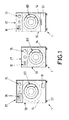
- the washing machine ensemble consists of three types of washing machines 1, namely a washing machine 1 of a first type (drawing on the left of Figure 1 ), a washing machine 1 of a second type (middle drawing in figure 1 ) having a height less than that of the machine 1 of the first type, and a washing machine 1 of a third type (drawing on the right in Figure 1 ) having a height greater than that of the second type machine 1 and equal to that of the machine 1 of the first type.
- Each washing machine comprises a frame with a housing 10.
- the housing 10 comprises a front panel 14 with a hole for a front loading door 60 and that provides access to a washing tub of an oscillating unit installed in the interior of the washing machine 1.
- a control panel 15 is installed on the front panel 14, and moreover a recess is provided for a detergent compartment 16.
- At the bottom of the washing machine 1 are installed, in an essentially conventional manner, support legs 57 that support the washer 1 and which permit the leveling thereof.
- the upper base of the washing machine 1 is covered by a top cover 17.
- the washing machine 1 of the second type has a height that is less than that of the first type, and is a compact washing machine intended to be built into a kitchen furnishings ensemble at half the height or to be arranged above another furnishing or appliance, for example, at a height from the kitchen floor of substantially greater than 1 meter, preferably greater than 1.50 meters.
- the front panel 14 has a lower height than that of the front panel 14 of the washing machine 1 of the first type, and extends from the upper base of the washing machine 1 to the upper edge of the upper front of a storage element in the form of a drawer 51 accommodated in the lower void volume of the washing machine 1.
- washing machines 1 illustrated in Figure 1 differ in their respective lower structures, but not in terms of having the same loading doors 60 that provide access equally to each of the wash tubs from the respective oscillating units located at the same distance from the upper base of the respective washing machines 1.
- Figure 2 can be seen embodiments of sheet materials 11 bent into a U that form the rear and side walls of the housings of two types of washing machines 1 that accommodate the same oscillating units in their interiors, as well as the elements for fixing the spring to frame 35 provided on the edges of opposite side of the respective sheet materials 11 bent into a U.
- the sides of the sheet materials 11 are downwardly interconnected by respective base plates 12 in the form of frontal stiffening profiles.
- the elements for fixing the spring to frame 35 serve to connect first ends of the respective retaining springs where the second ends thereof are connected to the washing tub.
- the bent sheet materials 11 form the respective side and rear walls of the housing 10.
- Figure 3 shows other embodiments of sheet materials 11 bent into a U, capable of forming the back and side walls of each of the housings for the two washers having different heights, according to another embodiment of the washing machine ensemble.
- the sheet materials 11 bent into a U are obtained from stamped sheet materials 11 which differ only in their bottoms.
- the first sheet materials 11 shown on the left side of Figure 3 have a lower band that is not present in the second sheet materials 11 shown on the right side of Figure 3 .
- the first sheet materials 11 serve to form the back wall and the side walls of a first washing machine
- the second sheet materials serve to form the back wall and the side walls of a second washing machine having a height that is less than that of the first washer, precisely corresponding with the height of the lower band that is present in the first sheet materials 11 but not present in the second sheet materials 11.
- the loading door and at least the washing tub can be the same and can be installed at the same distance from the respective upper bases of the two washing machines.
- the oscillating unit 20 illustrated in Figure 4 comprises, in an essentially conventional manner, a washing tub 21, a washing drum 22 rotating inside the tub 21, a motor 23 installed in the tub 21 that transmits rotational movement to the drum 22, a transmission that transmits the rotational movement of the motor to the drum (not shown in Figure 4 ), and counterweights 24 arranged in the outer periphery of the tub 21.
- the oscillating unit 20 is suspended at the top of the frame of the washing machine by means of helical retaining springs 40, and is supported by one or more oscillation dampers connected to the bottom of the frame.
- the springs 40 are engaged at their upper ends in fixing elements 35 provided at the top of the sides of the sheet material bent into a U (see Figure 2 ) and at their lower ends to the respective elements 36 for fixing the spring to tub 21 that are provided in the tub 21.
- Figure 4 also shows two types of oscillation dampers, namely, three linear dampers 30 and three radial dampers 32.
- damper 34 Provided in tub 21 are fixing elements from damper 34 that can connect to the respective upper ends of the linear dampers 30 or radial dampers 32. Selection of the damper type, linear or radial, depends on the height at which the oscillating unit 20 must be arranged on the type of washing machine to be produced. Thus, in the case of compact washing machines, for example, in washing machines with a reduced height that are built into kitchen furnishings, or in washing machines in which the bottom comprises storage elements such as drawers, baskets, or reservoirs, radial dampers 32 are preferably installed due to less vertical space being taken up thereby, while in most washing machines that are higher and do not have storage elements, linear dampers 30 can be installed.
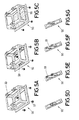
- FIGS 5A-5G illustrate embodiments of support units 50 fixable to the housing 10 of the first washing machine 1 and/or to the second housing 10 and/or other washing machines 1 provided with respective elements for fixing the damper to frame 33.
- the support unit 50 comprises a prismatic, slightly truncated pyramidal base frame of rectangular bases.
- the base frame 50 comprises a rectangular upper framework and a lower rectangular framework, each comprising a front bar and a rear bar, and side bars that join the front bar with the rear bar.
- the four corners of these frameworks are joined together by four vertical columns.
- Each of the vertical columns comprises a vertical accommodation, for example a thread, for one of the four support legs 57 of the washing machine.
- the lower framework of the base frame 50 is joined to the bottom sheet material that has an access cut-out and is screwable into the bottom of the frame of the washing machine.
- the damper In the side bars of the upper framework are arranged elements for fixing the damper to the frame 33 in the form of pairs of lugs that emerge from the upper surfaces of the side bars, specifically, one pair of lugs on the left side bar and two pairs of lugs the right side bar.
- the access cut-out in the bottom sheet material of the base frame 50 is sealed, in an essentially known manner, by a removable or at least hinged bottom cover, while the access cut-out in the bottom sheet material of base frame 50 shown in Figure 5C is sealed, also in an essentially known manner, by a water collection tray 55 ("Aquastop tray").
- the base frame 50 shown in Figure 5B further comprises three additional pairs of lugs that emerge above the side bars of the lower framework that are arranged analogously to the lugs of the upper framework.
- This embodiment has the advantage that the base frame 50 can be incorporated into different types of washing machines, for example, in first washing machines that do not have storage elements with linear oscillation dampers connected to the lugs 33 of the lower framework, and in second washing machines that do have storage elements with radial oscillation dampers connected to the lugs 33 of the upper framework, such that the space between the frameworks can accommodate a storage element, or in first washing machines having a first height and second washing machines having a second height that is less than the first height.
- FIGS 5D-5G refer to support units 50 that have in common the fact of comprising rectangular base plates having elements for fixing the damper to the frame 33 emerging from the upper surfaces thereof, and basically differ from each other in relation to the respective heights at which the damper is connected.
- the element for fixing the damper to the frame 33 from the support unit 50 is a pair of lugs with facing connection holes that enable the connection of the damper at a short distance from the base plate.
- This support unit 50 can be supplemented by another (not shown in Figures 5D-5G ), installable on the opposite side of the frame, comprising two pairs of lugs spaced apart, in analogy to the pairs of lugs present on the left bar of the frameworks illustrated in Figures 5A-5C , but with facing connection holes at the same distance from the base plate as the lug in Figure 5C .
- the elements for fixing the damper to the frame 33 from the support unit 50 are two pairs of lugs spaced apart, the facing connection holes thereof being spaced further from the base plate than those of the embodiment shown in Figure 5D .
- This support unit 50 can be supplemented by another (not shown in Figures 5D-5G ), installable on the opposite side of the frame, comprising one pair of lugs, in analogy to the pair of lugs present on the right bar in Figures 5A-5C , but with facing connection holes at the same distance from the base plate as the lug in Figure 5E .
- the elements for fixing the damper to the frame 33 from the support unit 50 are also two pairs of lugs spaced apart from each other.
- each pair of lugs comprises two facing pairs of connection holes located at different distances from the base plate, such that according to this embodiment, the dampers can be connected to the support unit at different heights.
- the support unit 50 shown in Figure 5F can be complemented by the support unit 50 shown in Figure 5G arrangeable on the opposite side of the frame, comprising a pair of lugs, in analogy to the pair of lugs present on the left bar in Figures 5A-5C , and also comprising two pairs of connecting holes that allow connection of the damper at the same heights as those of the pairs of lugs in Figure 5F .
- Figures 6A-6E show various possibilities of incorporating support units 50 such as those illustrated in Figures 5A-5G , in the sheet materials 11 bent into a U of the housings from different washing machines.
- the embodiment illustrated in Figure 6A shows the arrangement of the two support units previously described with reference to Figure 5D with respect to a first compact washing machine having a reduced height, namely the support unit 50 with a single pair of lugs illustrated in Figure 5D arranged on the left side of the bottom of the sheet materials 11, and the said other support unit 50 with two pairs of lugs on the right side of the bottom of the sheet material 11.
- the dampers can, for example, be radial dampers.
- FIG 6B shows the arrangement of the two support units previously described with reference to Figure 5E , in the sheet material 11 bent into a U from the housing of a second washing machine of conventional height.
- the support unit 50 illustrated with two pairs of lugs in Figure 5E is arranged on the right side of the bottom sheet material 11, and another said support unit with a single pair of lugs is disposed on the left side of the bottom of the sheet material 11.
- the dampers can, for example, be linear dampers.
- the embodiment illustrated in Figure 6C shows the arrangement of the support unit 50 in the form of a base frame as shown in Figure 5A in the sheet material 11 bent into a U from the housing of a third washing machine, also of conventional height, and suitable for incorporation of a storage element located between the upper and lower frameworks of the base frame.
- the dampers can, for example, be radial dampers.
- the embodiment illustrated in Figure 6D shows the arrangement of the two support units previously described with reference to Figure 5D with respect to a fourth washing machine of conventional height, namely the support unit 50 with a single pair of lugs illustrated in Figure 5D arranged on the left side of the bottom of the sheet material 11, and the said other support unit 50 with two pairs of lugs on the right side of the bottom of the sheet material 11.
- the dampers can, for example, be linear dampers.
- FIG. 6E shows the arrangement of the supporting unit frame 50 in the form of the base frame shown in Figure 5B in the sheet material 11 bent into a U of the housing of a fifth washing machine, also of conventional height, such that the oscillating unit of the washing machine can be connected to the pairs of lugs of the upper framework, for example, by means of radial dampers, in which case it is possible to incorporate a storage element located between the upper and lower frameworks of the base frame, or on the lower framework, for example, by means of linear dampers, when the washing machine is not intended to include such a storage element.
- FIG 7 shows two washing machines 1 of a washing machine ensemble according to an embodiment made from the sheet materials 11 and supporting units 50 illustrated in Figure 6E .
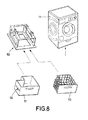
- FIG 8 shows an embodiment of a washing machine 1 with a housing 10 comprising a sheet material 11 bent into a U and a support unit 50 in the form of a base frame as illustrated in Figure 7C .
- the oscillating unit is supported by the base frame by means of radial dampers connected to the lugs 33 of the upper framework of the base frame, such that the space between the upper and lower frameworks can accommodate a storage element, such as is shown in Figure 8 , namely, a drawer 51 provided on the sides of the guide means 56 sliding on the complementary guide means (not shown in the figures) provided on the columns of the base frame 50, or a basket 52.
- a storage element such as is shown in Figure 8 , namely, a drawer 51 provided on the sides of the guide means 56 sliding on the complementary guide means (not shown in the figures) provided on the columns of the base frame 50, or a basket 52.
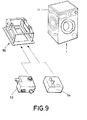
- FIG 9 shows an embodiment of a washing machine 1 with a housing 10 comprising a sheet material 11 bent into a U and a support unit 50 in the form of a base frame as illustrated in Figure 7C .
- the oscillating unit is supported by the base frame by means of radial dampers connected to the lugs 33 of the upper framework of the base frame.
- the space between the upper and lower frameworks accommodates a water reservoir 53 or a detergent dispenser 54.
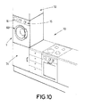
- Figure 10 shows the compact washing machine 1 of the second type previously described with reference to Figure 1 and the being built into a kitchen furnishing ensemble 70 thereof, particularly between a lower furnishing 71 on which it is supported, and an upper furnishing 72.
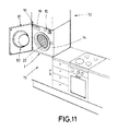
- Figure 11 shows another embodiment of a compact washing machine 1 built in between the lower furnishing 71 and the upper furnishing 72 of a kitchen furnishing ensemble.
- the front loading door 60 is integrated into a front cover 61 which in turn is laterally articulated lateral to the housing 10.
- the front cover 61 has dimensions such that, when closed, it covers the entire front surface of the washing machine 1.
- the control panel 15 and the recess for the detergent compartment 16 are arranged on top of the front panel 14 of the housing 10, which is only accessible when the front cover 61 is open.
- the loading door 60 is not integrated into the front cover 61 but, similar to the compact washing machine 1 described with reference to Figure 10 , is installed on the front panel 14 of the housing 10.
- control panel 15 and the detergent compartment have substantially triangular forms.
Landscapes
- Engineering & Computer Science (AREA)
- Textile Engineering (AREA)
- Main Body Construction Of Washing Machines And Laundry Dryers (AREA)
- Accessory Of Washing/Drying Machine, Commercial Washing/Drying Machine, Other Washing/Drying Machine (AREA)
Abstract
Description
- The present invention relates to the technical field of machines for washing laundry such as washing machines, dryers, and machines that combine the functions of washing and drying, and in particular in the area of washing machines that comprise common structural elements and other various uses in their mass production.
- Many of the manufacturers of washing machines such as washers, dryers, and machines that combine the washing and drying functions, offer washing machines with various exterior dimensions, such as, for example, various heights that depend on the location in which it will be situated, such as, for example, machines situated independently on the floor or machines built into kitchen furnishings.
- Each type of washing machine has a different housing, which also implies that at least the majority of the elements that comprise the respective oscillating units must be adapted to each type of machine, which is especially true in the case of housings for the types of washing machines that differ greatly from one another in terms of height, which can vary, for example, by at least 10% of the overall height. It is known that the "oscillating unit" of a washing machine generally comprises a washing tub, a washing drum that rotates inside the tub, a motor that transmits rotational movement to the drum, a transmission that transmits the rotational movement from the motor to the drum, and counterweights that define the dynamic behavior of the oscillating unit. The oscillating unit is typically suspended at the top of the frame of the washing machine by means of retaining springs, and is supported by one or more oscillation dampers connected to the bottom of the frame.
- The need to use a multitude of specialized oscillating units for washing machines with different housings is disadvantageous as it involves the need for these to be manufactured and stored separately, and because the mass assembly of washing machines with different housings requires, at least to a substantial extent, separate assembly lines and/or a laborious adaptation of the assembly line to the type of washing machine to be produced in each batch and/or the design of highly complex assembly lines that allow the assembly of different types of machines, all of which increases costs and delays in the process of manufacturing different types of washing machines.
- The present invention aims to overcome the drawbacks of the state of the art described above by means of a washing machine ensemble according to the independent claim attached. Preferred embodiments of this washing machine ensemble are defined in dependent claims attached, and are also subject of the subsequent disclosure and the drawing attached.
- In accordance with the invention, therefore, there is defined a washing machine ensemble comprising at least a first washing machine with a first housing, and at least a second washing machine with a second housing, wherein the first washing machine and the second washing machine respectively comprisine:
- an oscillating unit, with a tub connectable
- to the first housing, by means of at least a first damper of the linear type or the radial type, articulated at a first element for fixing the damper to a frame fixedly arranged with respect to the first housing and at a first height, and
- to the second housing, by means of at least a second damper of the radial type, articulated at a second element for fixing the damper to a frame fixedly arranged with respect to the second housing and at a second height greater than the first height by at least 10% of the total height of the second housing.
- The term "element for fixing the damper to a frame" as used in the present description refers to the element (for example a lug or a pair of lugs) of the frame to which the damper is joined. In turn, the term "element for fixing the damper to the tub" refers to the element provided in the tub for fixing the damper to tub, such as a nipple or projection.
- The term "frame" as used presently refers to an ensemble of structural components that cooperate to withstand static or dynamic loads from movement of the oscillating unit during operation of the washing machine. Thus, for example, as in the construction of conventional washing machines, the frame may comprise a metal sheet bent into a U. As with some manufacturers, the sheet material in the form of a U may constitute the side walls and rear wall of the housing, but as with other manufacturers a reverse configuration of the sheet material in the form of a U, that is, may constitute the side and front walls. The U-shaped sheet material forms part of the housing and the said frame itself. The frame may also comprise the support unit to which are fixed the lugs of the dampers and the support legs of the machine (adjustable height), as below. Other components of the "housing" apart from the U-shaped sheet material may be the front panel, the back cover and the front cover.
- The structure of the washing machine ensemble according to the invention facilitates production and improves the ability to produce different washing machines, in particular washing machines with different housings that have a different height, and in particular, washing machines with a drawer, basket, or reservoir accommodated in a bottom. This structure allows a single oscillating unit to be used for different types of washing machines that can be manufactured without disrupting a mass production. This is possible because at least two different types of dampers (linear and radial) may be employed, in combination with, for example, at least a single tub of an oscillating unit at different heights.
- The term "oscillating unit" used in the present description refers, as is generally known in the technical field to which the invention relates, to the ensemble of components, not including retaining springs and oscillation dampers that oscillate against the housing during the operation of the washing machine. The wash tub is the component of the washing machine that predominantly determines the necessary dimensions of the housing of the washing machine, and the forces that must be dampened by the oscillation dampers.
- The solution according to the invention permits the use of different types of dampers, preferably selected from among linear and radial dampers, to damp the movements of the oscillating units that comprise at least the tub itself arranged in the washing machines, for example, in washing machines of a single type, that have differences in height of at least 10%, preferably at least 25%, and most preferably 30%.
- Likewise, the use of a single tub construction allows the use of other common components that are not part of the oscillating unit itself, for example, such as the loading door of the washing machine that can have the same characteristics for manufacturing washing machine ensembles according to the present invention, or the retaining spring(s) through which, where appropriate, the oscillating unit can be fixed to the first housing and the second housing by means of retaining springs that comprise the same characteristics, and which bind to each of the upper edges of the housings bent toward the interior.
- This further contributes to improving the standardization of washing machine components for washing machines having different dimensions.
- Thus, the present invention involves a technical solution that facilitates production and improves productivity in the manufacture of washing machines of various types, for example within a range of washing machines from a single manufacturer, such as, for example, washing machines of different types that have the same or similar capabilities such as, for example, washing machines that can be built into kitchen furnishings, and washing machines that comprise, or not, a drawer, basket or reservoir accommodated in its bottom, wherein the damping requirements, that is, the resistant damping force, can be adapted using a damper for a specific oscillation to connect the tub to the housing, such as an essentially conventional linear damper, when having a "high" washing machine, or an essentially known radial damper such as, for example, the type described in
WO2011/070092 A1 , connected to the housing at a distance less than in the case of a machine of lower height. According to the invention, the first damper and the second damper can both be the same radial-type damper. - According to an embodiment of the invention, in the first washing machine and in the second washing machine, respectively, the oscillating unit further comprises a drum rotating within the tub, a motor, a transmission for driving the rotation of the drum, and a counterweight system. Thus it is possible to use not only the same tub construction but also the same constructions of the drum, the transmission, n and/or the counterweight system in the respective oscillating units in different washing machines that form the washing machine ensemble according to the present invention.
- According to another embodiment of the invention, the first housing of the first washing machine has a first height and the second housing of the second washing machine has a second height that is greater than the height of the first washing machine by least 10%, preferably at least 25%, more preferably at least 30% of the total height of the second housing. Thus, for example, It is possible to manufacture first washing machines that are 600 to 650 mm in height, and compact second washing machines with a height of approximately 850 mm, or washing machine ensembles with housings of the same height, wherein the housings of the first washing machines do not accommodate a drawer, basket or reservoir in the bottom, and the second machines do accommodate such a drawer, basket or reservoir. The difference in height between the first and second elements for fixing to the frame can be substantially the same as the difference in height between the first housing and the second housing.
- In a further embodiment of the invention, the first housing comprises a first sheet material bent into a U, and the second housing comprises a second sheet material bent into a U.
- According to a further development of this embodiment, the first sheet material can be die cut with the same die as for an area of the second sheet material.
- In another embodiment of the invention, the first washing machine and the second washing machine of the washing machine ensemble, respectively, comprises a front loading door fixable to the first housing and the second housing, that is, one fixable front door with structural characteristics that enable fixing either to the first housing or the second housing, such that is suitable for both the first washing machine as well as for the second washing machine.
- The washing machine ensemble according to the invention can comprise at least one support unit that is fixable to the first housing and/or the second housing and comprises at least one of the first elements for fixing the damper to the frame and/or at least one of the second elements for fixing the damper to the frame. According to this embodiment of the invention, each of the first washing machine and the second washing machine of the washing machine ensemble ca comprise a single support unit or various support units. In this case, considering the dynamic design of the washing machine, it is possible to design different types of support unit that are not connected to the housing, which facilitates a modular configuration of different types of washing machines based on different types of support unit, or a single support unit with fixing elements at different heights.
- Depending on whether the support unit is plastic or metal (preferably die-stamped or die-cut from a metal plate), fixing the support unit to the housings can be accomplished, for example, by TOX-clinching, riveting, or clipping (press-fitting). Conventionally, the support unit is a die-stamped plate with die-cut lugs on the same plate which is fixed from below the housing by TOX-clinching to a rib of the housing bent inwardly therefrom.
- Preferably, in each of the first washing machine and the second washing machine of the washing machine ensemble, the support unit is arranged inside the respective first or second housing, and, that is, not on a pedestal on which the washing machine rests, but rather inwardly from an element fixed to the housing. The support unit can be fixedly arranged at least partially on a lower base of the first housing or the second housing. Preferably, the support unit is arranged at the bottom of the washing machine.
- The support unit can be at least partially of plastic, and preferably can be molded in one piece, for example by injection.
- In the event that the washing machine is envisioned to comprise an "Aquastop" tray, that is, a water collection tray arranged in the bottom of the washing machine, this tray can be fixed to the bottom of the support unit or integrated thereinto.
- The elements for fixing the damper to the frame can be sheet metal fixable to the support unit of plastic, for example, by clipping. According to other possible embodiments, these elements for fixing can be integrated into the same support unit made of plastic. When the damper is a radial damper, the lugs can be metal, due to the construction of the friction joint itself, since it comprises a metallic tubular bushing that is trapped between the lugs through tightening the screw of the joint such that a friction sponge rigidly joined to the lever arm friction rubs against the bushing. The lugs can also be overmolded.
- According to an embodiment of the invention, the support unit can have a tetragonal or truncated pyramidal shape, and is formed by a base frame or by a prismatic or truncated pyramidal structure, for example, a structure of bars or profiles according the edges of a prism or truncated pyramid. The truncated pyramid structure facilitates the essentially usual assembly of the support unit ensemble from beneath the washing machine.
- The support unit, which can be configured as a plate, a base frame, or a prismatic structure, can also be shaped to accommodate an interior void volume greater than 50% of the minimum prismatic volume that surrounds the support unit.
- According to this embodiment, the washing machine ensemble can comprise at least one storage element accommodated in the interior void volume, preferably selected from the group consisting drawers, baskets, reservoirs, and combinations thereof. This storage element can be fixed to the support unit in a fixed or removable manner. Thus, the storage element can be fixed to the support unit such as to be horizontally and frontally removable from the interior void volume by means of the guide means of the storage element in the support unit.
- Aspects and embodiments of the invention are described below with reference to the figures of the drawing attached, wherein:
- Figure 1
- is a schematic frontal elevation view of three washing machines that make up a washing machine ensemble ;
- Figure 2
- is a front perspective view of each of the sheet materials bent into a U and bases of two washing machines that make up a washing machine ensemble;
- Figure 3
- shows the front view of another configuration of the sheet materials that form part of the housings of two washing machines that make up another washing machine ensemble, before and after being bent into a U;
- Figure 4
- shows, in front view, an embodiment of a washing tub that can be incorporated in either of the washing machines that make up a washing machine ensemble, as well as oscillation dampers and retaining springs connectable to this washing tub;
- Figures 5A-5G
- show, in frontal perspective, embodiments of various types of support units incorporatable into a washing machine ensemble;
- Figures 6A-6E
- show, in frontal perspective, the incorporation of support units into various types of housings for washing machines that make up a washing machine ensemble;
- Figure 7
- shows, in frontal perspective, another embodiment of two washing machines that make up a washing machine ensemble;
- Figure 8
- shows, in frontal perspective, an embodiment of a first washing machine that incorporates a support, and alternative embodiments of the storage element that can be accommodated in the interior void volume of the support;
- Figure 9
- shows, in frontal perspective, an embodiment of a second washing machine that incorporates a support, and other embodiments of the storage element that can be accommodated in the interior void volume of the support of the washing machine;
- Figure 10
- is a perspective view of an embodiment of a compact washing machine that can form part of a washing machine ensemble, and the building into a kitchen furnishing ensemble thereof;
- Figure 11
- is a perspective view of an embodiment of another compact washing machine that can form part of a washing machine ensemble, and the building into a kitchen furnishing ensemble thereof;
- Figure 12
- is a perspective view of an embodiment of another compact washing machine that can form part of a washing machine ensemble, and the building into a kitchen furnishing ensemble thereof; and
- Figure 13
- is a perspective view of another embodiment of another compact washing machine that can form part of a washing machine ensemble, and the building into a kitchen furnishing ensemble thereof.
- The washing machine ensemble consists of three types of
washing machines 1, namely awashing machine 1 of a first type (drawing on the left ofFigure 1 ), awashing machine 1 of a second type (middle drawing infigure 1 ) having a height less than that of themachine 1 of the first type, and awashing machine 1 of a third type (drawing on the right inFigure 1 ) having a height greater than that of thesecond type machine 1 and equal to that of themachine 1 of the first type. - Each washing machine comprises a frame with a
housing 10. Thehousing 10 comprises afront panel 14 with a hole for afront loading door 60 and that provides access to a washing tub of an oscillating unit installed in the interior of thewashing machine 1. Acontrol panel 15 is installed on thefront panel 14, and moreover a recess is provided for adetergent compartment 16. At the bottom of thewashing machine 1 are installed, in an essentially conventional manner, supportlegs 57 that support thewasher 1 and which permit the leveling thereof. The upper base of thewashing machine 1 is covered by atop cover 17. - The
washing machine 1 of the first type is intended to be located, in an essentially conventional manner, directly on the floor, and thefront panel 14 has an opening for acover 18 that is removable to allow access to the motor pump which is located inside thewashing machine 1. Thiscover 18 is not present in thewashing machines 1 of the second and third type. - The
washing machine 1 of the second type has a height that is less than that of the first type, and is a compact washing machine intended to be built into a kitchen furnishings ensemble at half the height or to be arranged above another furnishing or appliance, for example, at a height from the kitchen floor of substantially greater than 1 meter, preferably greater than 1.50 meters. - In the
washing machine 1 of the third type, thefront panel 14 has a lower height than that of thefront panel 14 of thewashing machine 1 of the first type, and extends from the upper base of thewashing machine 1 to the upper edge of the upper front of a storage element in the form of adrawer 51 accommodated in the lower void volume of thewashing machine 1. - The three types of
washing machines 1 illustrated inFigure 1 differ in their respective lower structures, but not in terms of having thesame loading doors 60 that provide access equally to each of the wash tubs from the respective oscillating units located at the same distance from the upper base of therespective washing machines 1. - In
Figure 2 can be seen embodiments ofsheet materials 11 bent into a U that form the rear and side walls of the housings of two types ofwashing machines 1 that accommodate the same oscillating units in their interiors, as well as the elements for fixing the spring to frame 35 provided on the edges of opposite side of therespective sheet materials 11 bent into a U. - The sides of the
sheet materials 11 are downwardly interconnected byrespective base plates 12 in the form of frontal stiffening profiles. - The elements for fixing the spring to frame 35 serve to connect first ends of the respective retaining springs where the second ends thereof are connected to the washing tub. The
bent sheet materials 11 form the respective side and rear walls of thehousing 10. -
Figure 3 shows other embodiments ofsheet materials 11 bent into a U, capable of forming the back and side walls of each of the housings for the two washers having different heights, according to another embodiment of the washing machine ensemble. - According to this embodiment, the
sheet materials 11 bent into a U are obtained from stampedsheet materials 11 which differ only in their bottoms. Thus, thefirst sheet materials 11 shown on the left side ofFigure 3 have a lower band that is not present in thesecond sheet materials 11 shown on the right side ofFigure 3 . In this way, once bent into a U, thefirst sheet materials 11 serve to form the back wall and the side walls of a first washing machine, while, once bent into U, the second sheet materials serve to form the back wall and the side walls of a second washing machine having a height that is less than that of the first washer, precisely corresponding with the height of the lower band that is present in thefirst sheet materials 11 but not present in thesecond sheet materials 11. In both washing machines, however, the loading door and at least the washing tub can be the same and can be installed at the same distance from the respective upper bases of the two washing machines. - The oscillating
unit 20 illustrated inFigure 4 comprises, in an essentially conventional manner, awashing tub 21, awashing drum 22 rotating inside thetub 21, amotor 23 installed in thetub 21 that transmits rotational movement to thedrum 22, a transmission that transmits the rotational movement of the motor to the drum (not shown inFigure 4 ), andcounterweights 24 arranged in the outer periphery of thetub 21. The oscillatingunit 20 is suspended at the top of the frame of the washing machine by means of helical retaining springs 40, and is supported by one or more oscillation dampers connected to the bottom of the frame. - The
springs 40 are engaged at their upper ends in fixingelements 35 provided at the top of the sides of the sheet material bent into a U (seeFigure 2 ) and at their lower ends to therespective elements 36 for fixing the spring totub 21 that are provided in thetub 21. - Depicted below the oscillating
unit 20,Figure 4 also shows two types of oscillation dampers, namely, threelinear dampers 30 and threeradial dampers 32. - Provided in
tub 21 are fixing elements fromdamper 34 that can connect to the respective upper ends of thelinear dampers 30 orradial dampers 32. Selection of the damper type, linear or radial, depends on the height at which theoscillating unit 20 must be arranged on the type of washing machine to be produced. Thus, in the case of compact washing machines, for example, in washing machines with a reduced height that are built into kitchen furnishings, or in washing machines in which the bottom comprises storage elements such as drawers, baskets, or reservoirs,radial dampers 32 are preferably installed due to less vertical space being taken up thereby, while in most washing machines that are higher and do not have storage elements,linear dampers 30 can be installed. -
Figures 5A-5G illustrate embodiments ofsupport units 50 fixable to thehousing 10 of thefirst washing machine 1 and/or to thesecond housing 10 and/orother washing machines 1 provided with respective elements for fixing the damper to frame 33. - In each of the embodiments illustrated in
Figures 5A-5C , thesupport unit 50 comprises a prismatic, slightly truncated pyramidal base frame of rectangular bases. Thebase frame 50 comprises a rectangular upper framework and a lower rectangular framework, each comprising a front bar and a rear bar, and side bars that join the front bar with the rear bar. The four corners of these frameworks are joined together by four vertical columns. Each of the vertical columns comprises a vertical accommodation, for example a thread, for one of the foursupport legs 57 of the washing machine. The lower framework of thebase frame 50 is joined to the bottom sheet material that has an access cut-out and is screwable into the bottom of the frame of the washing machine. In the side bars of the upper framework are arranged elements for fixing the damper to theframe 33 in the form of pairs of lugs that emerge from the upper surfaces of the side bars, specifically, one pair of lugs on the left side bar and two pairs of lugs the right side bar. - As illustrated in
Figures 5A and 5B , the access cut-out in the bottom sheet material of thebase frame 50 is sealed, in an essentially known manner, by a removable or at least hinged bottom cover, while the access cut-out in the bottom sheet material ofbase frame 50 shown inFigure 5C is sealed, also in an essentially known manner, by a water collection tray 55 ("Aquastop tray"). - Besides the lugs emerging from the upper framework, the
base frame 50 shown inFigure 5B further comprises three additional pairs of lugs that emerge above the side bars of the lower framework that are arranged analogously to the lugs of the upper framework. This embodiment has the advantage that thebase frame 50 can be incorporated into different types of washing machines, for example, in first washing machines that do not have storage elements with linear oscillation dampers connected to thelugs 33 of the lower framework, and in second washing machines that do have storage elements with radial oscillation dampers connected to thelugs 33 of the upper framework, such that the space between the frameworks can accommodate a storage element, or in first washing machines having a first height and second washing machines having a second height that is less than the first height. - The embodiments illustrated in
Figures 5D-5G refer to supportunits 50 that have in common the fact of comprising rectangular base plates having elements for fixing the damper to theframe 33 emerging from the upper surfaces thereof, and basically differ from each other in relation to the respective heights at which the damper is connected. - Thus, in the embodiment of
Figure 5D , the element for fixing the damper to theframe 33 from thesupport unit 50 is a pair of lugs with facing connection holes that enable the connection of the damper at a short distance from the base plate. Thissupport unit 50 can be supplemented by another (not shown inFigures 5D-5G ), installable on the opposite side of the frame, comprising two pairs of lugs spaced apart, in analogy to the pairs of lugs present on the left bar of the frameworks illustrated inFigures 5A-5C , but with facing connection holes at the same distance from the base plate as the lug inFigure 5C . - In the embodiment illustrated in
Figure 5E , the elements for fixing the damper to theframe 33 from thesupport unit 50 are two pairs of lugs spaced apart, the facing connection holes thereof being spaced further from the base plate than those of the embodiment shown inFigure 5D . Thissupport unit 50 can be supplemented by another (not shown inFigures 5D-5G ), installable on the opposite side of the frame, comprising one pair of lugs, in analogy to the pair of lugs present on the right bar inFigures 5A-5C , but with facing connection holes at the same distance from the base plate as the lug inFigure 5E . - For the
support unit 50 shown in the embodiment according toFigure 5F , the elements for fixing the damper to theframe 33 from thesupport unit 50 are also two pairs of lugs spaced apart from each other. However, each pair of lugs comprises two facing pairs of connection holes located at different distances from the base plate, such that according to this embodiment, the dampers can be connected to the support unit at different heights. Thesupport unit 50 shown inFigure 5F can be complemented by thesupport unit 50 shown inFigure 5G arrangeable on the opposite side of the frame, comprising a pair of lugs, in analogy to the pair of lugs present on the left bar inFigures 5A-5C , and also comprising two pairs of connecting holes that allow connection of the damper at the same heights as those of the pairs of lugs inFigure 5F . -
Figures 6A-6E show various possibilities of incorporatingsupport units 50 such as those illustrated inFigures 5A-5G , in thesheet materials 11 bent into a U of the housings from different washing machines. - Thus, the embodiment illustrated in
Figure 6A shows the arrangement of the two support units previously described with reference toFigure 5D with respect to a first compact washing machine having a reduced height, namely thesupport unit 50 with a single pair of lugs illustrated inFigure 5D arranged on the left side of the bottom of thesheet materials 11, and the saidother support unit 50 with two pairs of lugs on the right side of the bottom of thesheet material 11. In this case, the dampers can, for example, be radial dampers. - The embodiment illustrated in
Figure 6B shows the arrangement of the two support units previously described with reference toFigure 5E , in thesheet material 11 bent into a U from the housing of a second washing machine of conventional height. As can be seen, thesupport unit 50 illustrated with two pairs of lugs inFigure 5E is arranged on the right side of thebottom sheet material 11, and another said support unit with a single pair of lugs is disposed on the left side of the bottom of thesheet material 11. In this case, the dampers can, for example, be linear dampers. - Meanwhile, the embodiment illustrated in
Figure 6C shows the arrangement of thesupport unit 50 in the form of a base frame as shown inFigure 5A in thesheet material 11 bent into a U from the housing of a third washing machine, also of conventional height, and suitable for incorporation of a storage element located between the upper and lower frameworks of the base frame. In this case, the dampers can, for example, be radial dampers. - The embodiment illustrated in
Figure 6D shows the arrangement of the two support units previously described with reference toFigure 5D with respect to a fourth washing machine of conventional height, namely thesupport unit 50 with a single pair of lugs illustrated inFigure 5D arranged on the left side of the bottom of thesheet material 11, and the saidother support unit 50 with two pairs of lugs on the right side of the bottom of thesheet material 11. In this case, the dampers can, for example, be linear dampers. - Finally, the embodiment illustrated in
Figure 6E shows the arrangement of the supportingunit frame 50 in the form of the base frame shown inFigure 5B in thesheet material 11 bent into a U of the housing of a fifth washing machine, also of conventional height, such that the oscillating unit of the washing machine can be connected to the pairs of lugs of the upper framework, for example, by means of radial dampers, in which case it is possible to incorporate a storage element located between the upper and lower frameworks of the base frame, or on the lower framework, for example, by means of linear dampers, when the washing machine is not intended to include such a storage element. -
Figure 7 shows twowashing machines 1 of a washing machine ensemble according to an embodiment made from thesheet materials 11 and supportingunits 50 illustrated inFigure 6E . - In the
housing 10 of thefirst washing machine 1 shown in the drawing on the left ofFigure 7 , which corresponds to thewashing machine 1 of the first type shown inFigure 1 , the oscillating unit is supported by linear oscillators connected to the lugs of the upper framework of thesupport unit 50, while in thesecond washing machine 1 shown in the drawing on the right ofFigure 7 , the oscillating unit is supported by radial dampers, all in accordance with that previously described with reference toFigures 5C and6E . -
Figure 8 shows an embodiment of awashing machine 1 with ahousing 10 comprising asheet material 11 bent into a U and asupport unit 50 in the form of a base frame as illustrated inFigure 7C . - The oscillating unit is supported by the base frame by means of radial dampers connected to the
lugs 33 of the upper framework of the base frame, such that the space between the upper and lower frameworks can accommodate a storage element, such as is shown inFigure 8 , namely, adrawer 51 provided on the sides of the guide means 56 sliding on the complementary guide means (not shown in the figures) provided on the columns of thebase frame 50, or abasket 52. -
Figure 9 shows an embodiment of awashing machine 1 with ahousing 10 comprising asheet material 11 bent into a U and asupport unit 50 in the form of a base frame as illustrated inFigure 7C . - Also in the case of this embodiment, the oscillating unit is supported by the base frame by means of radial dampers connected to the
lugs 33 of the upper framework of the base frame. However, the space between the upper and lower frameworks accommodates awater reservoir 53 or adetergent dispenser 54. -
Figure 10 shows thecompact washing machine 1 of the second type previously described with reference toFigure 1 and the being built into akitchen furnishing ensemble 70 thereof, particularly between alower furnishing 71 on which it is supported, and anupper furnishing 72. -
Figure 11 shows another embodiment of acompact washing machine 1 built in between thelower furnishing 71 and theupper furnishing 72 of a kitchen furnishing ensemble. - In this case, the
front loading door 60 is integrated into afront cover 61 which in turn is laterally articulated lateral to thehousing 10. Thefront cover 61 has dimensions such that, when closed, it covers the entire front surface of thewashing machine 1. Thecontrol panel 15 and the recess for thedetergent compartment 16 are arranged on top of thefront panel 14 of thehousing 10, which is only accessible when thefront cover 61 is open. - The
compact washing machine 1 shown in the embodiment illustrated inFigure 12 is also designed to be built in between anupper furnishing 71 and thelower furnishing 72 of the kitchen furnishing ensemble. Similarly to the embodiment described with reference toFigure 11 , thecontrol panel 15 and the recess for thedetergent compartment 16 are arranged on top of thefront panel 14 of thehousing 10. - Although the
washing machine 1 corresponding to this embodiment also comprises a front cover dimensioned such that, when closed, it covers the entire front surface of thewashing machine 1, and is a hinged cover that is articulated at the bottom of thehousing 10 such that in the open position, it serves to holdlaundry 62 to be introduced into or to be removed from thewashing machine 1. - Furthermore, according to this embodiment, the
loading door 60 is not integrated into thefront cover 61 but, similar to thecompact washing machine 1 described with reference toFigure 10 , is installed on thefront panel 14 of thehousing 10. - The
compact washing machine 1 illustrated inFigure 13 comprises afront loading door 60 having dimensions substantially larger than that illustrated in theFigures 10 to 12 and occupies the majority of thefront panel 14 of the housing, whereby thedetergent compartment 16 and thecontrol panel 15 are arranged in diagonally opposite corners of the front of thewashing machine 1. - The
control panel 15 and the detergent compartment have substantially triangular forms. -
- 1
- Washing machine
- 10
- Housing
- 11
- Sheet material of the housing
- 12
- Base plate
- 13
- Frame
- 14
- Front panel
- 15
- Control panel
- 16
- Detergent compartment
- 17
- Top cover
- 18
- Motor pump cover
- 20
- Oscillating unit
- 21
- Tub
- 22
- Drum
- 23
- Motor
- 24
- Counterweight
- 30
- Linear damper
- 32
- Radial damper
- 33
- Element for fixing the damper to the frame
- 34
- Element for fixing the damper to the tub
- 35
- Element for fixing the spring to the frame
- 36
- Element for fixing the spring to the tub
- 40
- Spring
- 50
- Support unit
- 51
- Drawer
- 52
- Basket
- 53
- Reservoir
- 54
- Detergent dispenser
- 55
- Water collection tray
- 56
- Guiding means
- 57
- Support leg for the washing machine
- 60
- Front loading door
- 61
- Front cover
- 62
- Laundry
- 70
- Kitchen furnishing ensemble
- 71
- Lower furnishing
- 72
- Upper furnishing
Claims (13)
- Washing machine ensemble, comprising a first washing machine (1) with a first housing (10), and a second washing machine (1) with a second housing (10), characterized in the first washing machine (1) and the second washing machine (1) respectively comprising
an oscillating unit (20), with a tub (21) connectableto the first housing (10), by means of at least a first damper (30, 32) of the linear type or radial type, articulated at a first element for fixing the first damper (30, 32) to the frame (33) fixedly arranged with respect to the first housing (10) and at a first height, andto the second housing (10), by means of at least a second damper (32) of the radial type, articulated at a second element for fixing the second damper (32) to the frame (33) fixedly arranged with respect to the second housing (10) and at a second height greater than the first height by at least 10% of the total height of the second housing (10). - Washing machine ensemble according to claim 1, characterized in that in the first washing machine (1) and the second washing machine (1), respectively, the oscillating unit (20) additionally comprises a drum (22) rotating within the tub (21), a motor (23) and a transmission to drive the rotation of the drum (22), and a counterweight system (24).
- Washing machine ensemble according to one of the foregoing claims, characterized in that
the first housing (10) has a first height and the second housing (10) has a second height greater than the first height by at least 10% of the total height of the second housing (10). - Washing machine ensemble according to one of the foregoing claims, characterized in that the first housing (10) has a first sheet material (11) bent into a U and the second housing (10) has a second sheet material (11) bent into a U.
- Washing machine ensemble according to claim 4, characterized in that at least one area of the first sheet material (11) is die cut with the same die as an area of the second sheet material (11).
- Washing machine ensemble according to one of the foregoing claims, characterized in the first washing machine (1) and the second washing machine (1) respectively comprising a front loading door (60) fixable to the first housing (10) and the second housing (10).
- Washing machine ensemble according to one of the foregoing claims, characterized in the first washing machine (1) and the second washing machine (1) respectively comprising a support unit (50) fixable to the first housing (10) and/or to the second housing (10) and comprising at least one of the first elements for fixing the damper to the frame (33) and/or at least one of the second elements for fixing the damper to the frame (33).
- Washing machine ensemble according to claim 7, characterized in that in the first washing machine (1) and the second washing machine (1), respectively, the support unit (50) is arranged within the first housing (10) and within the second housing (10).
- Washing machine ensemble according to one of claims 7 and 8, characterized in that in the first washing machine (1) and the second washing machine (1), respectively, the support unit (50) is formed to accommodate an interior void volume greater than 50% of the minimum prismatic volume that envelops the support unit (50).
- Washing machine ensemble according to claim 9, characterized in comprising at least one storage element (51, 52, 53) accommodatable in the interior void volume, preferably selected from the group including: a drawer (51), a basket (52), a reservoir (53), and a combination of the foregoing.
- Washing machine ensemble according to claim 10, characterized in that the storage element (51, 52, 53) is fixable to the support unit (50) in a fixed or removable manner.
- Washing machine ensemble according to claim 11, characterized in that the storage element (51, 52, 53) is fixable to the support unit (50) in a horizontally or frontally removable manner by means of guiding means (56) of the storage element (51, 52, 53) in the support unit (50).
- Washing machine ensemble according to one of the foregoing claims, characterized in that the first damper and the second damper are of the same radial type damper (32).
Applications Claiming Priority (1)
| Application Number | Priority Date | Filing Date | Title |
|---|---|---|---|
| ES201331927A ES2539434B1 (en) | 2013-12-28 | 2013-12-28 | WASHING MACHINE SET |
Publications (1)
| Publication Number | Publication Date |
|---|---|
| EP2889416A1 true EP2889416A1 (en) | 2015-07-01 |
Family
ID=52146287
Family Applications (1)
| Application Number | Title | Priority Date | Filing Date |
|---|---|---|---|
| EP14199720.5A Ceased EP2889416A1 (en) | 2013-12-28 | 2014-12-22 | Washing machine ensemble comprising a first washing machine and a second washing machine |
Country Status (2)
| Country | Link |
|---|---|
| EP (1) | EP2889416A1 (en) |
| ES (1) | ES2539434B1 (en) |
Cited By (2)
| Publication number | Priority date | Publication date | Assignee | Title |
|---|---|---|---|---|
| CN110777516A (en) * | 2019-12-13 | 2020-02-11 | 山东小鸭集团家电有限公司 | Washing machine face frame |
| EP3497276B1 (en) | 2016-08-10 | 2020-12-02 | BSH Hausgeräte GmbH | Laundry treatment device |
Families Citing this family (1)
| Publication number | Priority date | Publication date | Assignee | Title |
|---|---|---|---|---|
| CN113529332B (en) * | 2020-04-14 | 2025-06-20 | 青岛海尔滚筒洗衣机有限公司 | Support structure for clothing processing equipment and clothing processing equipment |
Citations (5)
| Publication number | Priority date | Publication date | Assignee | Title |
|---|---|---|---|---|
| US3197983A (en) * | 1961-08-23 | 1965-08-03 | Clemens August Voigt | Resilient support for rotor assembly |
| DE1938536A1 (en) * | 1968-07-30 | 1970-02-05 | Hoover Ltd | Washing machine and / or spinning machine |
| GB2078882A (en) * | 1980-06-23 | 1982-01-13 | Hotpoint Ltd | Oscillation damping equipment |
| WO2011070092A1 (en) | 2009-12-10 | 2011-06-16 | BSH Bosch und Siemens Hausgeräte GmbH | Household appliance, in particular a washing machine or dryer |
| WO2013175372A1 (en) * | 2012-05-23 | 2013-11-28 | BSH Bosch und Siemens Hausgeräte GmbH | Rotary damping device for electrical household appliance |
-
2013
- 2013-12-28 ES ES201331927A patent/ES2539434B1/en not_active Revoked
-
2014
- 2014-12-22 EP EP14199720.5A patent/EP2889416A1/en not_active Ceased
Patent Citations (5)
| Publication number | Priority date | Publication date | Assignee | Title |
|---|---|---|---|---|
| US3197983A (en) * | 1961-08-23 | 1965-08-03 | Clemens August Voigt | Resilient support for rotor assembly |
| DE1938536A1 (en) * | 1968-07-30 | 1970-02-05 | Hoover Ltd | Washing machine and / or spinning machine |
| GB2078882A (en) * | 1980-06-23 | 1982-01-13 | Hotpoint Ltd | Oscillation damping equipment |
| WO2011070092A1 (en) | 2009-12-10 | 2011-06-16 | BSH Bosch und Siemens Hausgeräte GmbH | Household appliance, in particular a washing machine or dryer |
| WO2013175372A1 (en) * | 2012-05-23 | 2013-11-28 | BSH Bosch und Siemens Hausgeräte GmbH | Rotary damping device for electrical household appliance |
Cited By (3)
| Publication number | Priority date | Publication date | Assignee | Title |
|---|---|---|---|---|
| EP3497276B1 (en) | 2016-08-10 | 2020-12-02 | BSH Hausgeräte GmbH | Laundry treatment device |
| CN110777516A (en) * | 2019-12-13 | 2020-02-11 | 山东小鸭集团家电有限公司 | Washing machine face frame |
| CN110777516B (en) * | 2019-12-13 | 2023-06-20 | 山东小鸭集团家电有限公司 | Washing machine face frame |
Also Published As
| Publication number | Publication date |
|---|---|
| ES2539434B1 (en) | 2016-06-23 |
| ES2539434A2 (en) | 2015-06-30 |
| ES2539434R1 (en) | 2015-09-18 |
Similar Documents
| Publication | Publication Date | Title |
|---|---|---|
| AU2008332194B2 (en) | Laundry machine | |
| EP1621660B1 (en) | Supporter for clothes washing machine and clothes drying apparatus | |
| EP2155948B1 (en) | Laundry machine | |
| KR101461950B1 (en) | washer | |
| EP1903136A1 (en) | Washing machine | |
| EP2152951B1 (en) | Laundry machine | |
| US20080178634A1 (en) | Laundry machine | |
| EP2154286B1 (en) | Ball balancer and laundry apparatus having the same | |
| US7533548B2 (en) | Drum type washing machine | |
| JP6722202B2 (en) | Washing machine with laundry classification function | |
| US9603500B2 (en) | Domestic appliance | |
| US9534334B2 (en) | Laundry treating appliance with a suspension assembly and a suspension assembly | |
| EP3293303A1 (en) | Laundry treating appliance with a slidable dispenser | |
| EP2643512A1 (en) | Home appliance with a vibration damping device and vibration damping device thereof | |
| WO1999045189A1 (en) | Improved machine for washing and/or drying clothes | |
| EP3064633A1 (en) | Laundry treatment appliance with user interface | |
| US5533367A (en) | Appliance shipping restraint assembly | |
| ES2539434B1 (en) | WASHING MACHINE SET | |
| US8646190B2 (en) | Laundry dryer | |
| US10221515B2 (en) | Laundry treating appliance and dispenser | |
| CN108729129A (en) | Washing machine | |
| EP3345528B1 (en) | Dishwasher base structure | |
| KR20210111632A (en) | Washing machine | |
| US20230026129A1 (en) | Appliance lid that incorporates interior structural foam reinforcement | |
| US10253442B2 (en) | Top-loading type washing machine |
Legal Events
| Date | Code | Title | Description |
|---|---|---|---|
| PUAI | Public reference made under article 153(3) epc to a published international application that has entered the european phase |
Free format text: ORIGINAL CODE: 0009012 |
|
| 17P | Request for examination filed |
Effective date: 20141222 |
|
| AK | Designated contracting states |
Kind code of ref document: A1 Designated state(s): AL AT BE BG CH CY CZ DE DK EE ES FI FR GB GR HR HU IE IS IT LI LT LU LV MC MK MT NL NO PL PT RO RS SE SI SK SM TR |
|
| AX | Request for extension of the european patent |
Extension state: BA ME |
|
| R17P | Request for examination filed (corrected) |
Effective date: 20160104 |
|
| RBV | Designated contracting states (corrected) |
Designated state(s): AL AT BE BG CH CY CZ DE DK EE ES FI FR GB GR HR HU IE IS IT LI LT LU LV MC MK MT NL NO PL PT RO RS SE SI SK SM TR |
|
| 17Q | First examination report despatched |
Effective date: 20160524 |
|
| 18R | Application refused |
Effective date: 20180730 |