EP2889177A1 - Wireless power transmission in electric vehicles - Google Patents
Wireless power transmission in electric vehicles Download PDFInfo
- Publication number
- EP2889177A1 EP2889177A1 EP15150222.6A EP15150222A EP2889177A1 EP 2889177 A1 EP2889177 A1 EP 2889177A1 EP 15150222 A EP15150222 A EP 15150222A EP 2889177 A1 EP2889177 A1 EP 2889177A1
- Authority
- EP
- European Patent Office
- Prior art keywords
- power
- antenna
- bev
- converter
- wireless power
- Prior art date
- Legal status (The legal status is an assumption and is not a legal conclusion. Google has not performed a legal analysis and makes no representation as to the accuracy of the status listed.)
- Granted
Links
- 230000005540 biological transmission Effects 0.000 title description 20
- 238000007600 charging Methods 0.000 claims abstract description 107
- 230000008878 coupling Effects 0.000 claims abstract description 32
- 238000010168 coupling process Methods 0.000 claims abstract description 32
- 238000005859 coupling reaction Methods 0.000 claims abstract description 32
- 230000002457 bidirectional effect Effects 0.000 claims abstract description 26
- 230000006978 adaptation Effects 0.000 claims description 42
- 238000000034 method Methods 0.000 claims description 35
- 239000003990 capacitor Substances 0.000 claims description 30
- 238000012937 correction Methods 0.000 claims description 18
- 230000007423 decrease Effects 0.000 claims description 10
- 230000008859 change Effects 0.000 claims description 8
- 238000004146 energy storage Methods 0.000 claims description 5
- 238000005070 sampling Methods 0.000 claims 2
- 238000012546 transfer Methods 0.000 abstract description 51
- 238000010586 diagram Methods 0.000 description 72
- 238000006243 chemical reaction Methods 0.000 description 57
- 238000004891 communication Methods 0.000 description 47
- 229910000859 α-Fe Inorganic materials 0.000 description 29
- 241000709691 Enterovirus E Species 0.000 description 20
- 238000013459 approach Methods 0.000 description 18
- 230000006870 function Effects 0.000 description 15
- 230000002441 reversible effect Effects 0.000 description 15
- 238000001914 filtration Methods 0.000 description 13
- 238000003860 storage Methods 0.000 description 12
- 230000009466 transformation Effects 0.000 description 11
- 230000001965 increasing effect Effects 0.000 description 7
- 238000005516 engineering process Methods 0.000 description 6
- 230000008569 process Effects 0.000 description 6
- 230000005855 radiation Effects 0.000 description 6
- 230000001360 synchronised effect Effects 0.000 description 6
- 238000009826 distribution Methods 0.000 description 5
- 230000005611 electricity Effects 0.000 description 5
- 229910001416 lithium ion Inorganic materials 0.000 description 5
- 230000033001 locomotion Effects 0.000 description 5
- 230000001902 propagating effect Effects 0.000 description 5
- 238000001228 spectrum Methods 0.000 description 5
- 238000013461 design Methods 0.000 description 4
- 230000005672 electromagnetic field Effects 0.000 description 4
- 238000007726 management method Methods 0.000 description 4
- 239000000463 material Substances 0.000 description 4
- 238000000926 separation method Methods 0.000 description 4
- 230000008901 benefit Effects 0.000 description 3
- 230000003139 buffering effect Effects 0.000 description 3
- 238000011161 development Methods 0.000 description 3
- 238000009499 grossing Methods 0.000 description 3
- 230000003287 optical effect Effects 0.000 description 3
- 230000009467 reduction Effects 0.000 description 3
- XLYOFNOQVPJJNP-UHFFFAOYSA-N water Substances O XLYOFNOQVPJJNP-UHFFFAOYSA-N 0.000 description 3
- 239000002253 acid Substances 0.000 description 2
- 230000006399 behavior Effects 0.000 description 2
- 238000011217 control strategy Methods 0.000 description 2
- 230000000694 effects Effects 0.000 description 2
- 230000008713 feedback mechanism Effects 0.000 description 2
- 239000000835 fiber Substances 0.000 description 2
- 230000001939 inductive effect Effects 0.000 description 2
- 238000002156 mixing Methods 0.000 description 2
- 238000005457 optimization Methods 0.000 description 2
- 239000002245 particle Substances 0.000 description 2
- 239000007787 solid Substances 0.000 description 2
- 230000000087 stabilizing effect Effects 0.000 description 2
- 101150012579 ADSL gene Proteins 0.000 description 1
- 102100020775 Adenylosuccinate lyase Human genes 0.000 description 1
- 108700040193 Adenylosuccinate lyases Proteins 0.000 description 1
- RYGMFSIKBFXOCR-UHFFFAOYSA-N Copper Chemical compound [Cu] RYGMFSIKBFXOCR-UHFFFAOYSA-N 0.000 description 1
- 208000034423 Delivery Diseases 0.000 description 1
- JNCMHMUGTWEVOZ-UHFFFAOYSA-N F[CH]F Chemical compound F[CH]F JNCMHMUGTWEVOZ-UHFFFAOYSA-N 0.000 description 1
- WHXSMMKQMYFTQS-UHFFFAOYSA-N Lithium Chemical compound [Li] WHXSMMKQMYFTQS-UHFFFAOYSA-N 0.000 description 1
- HBBGRARXTFLTSG-UHFFFAOYSA-N Lithium ion Chemical compound [Li+] HBBGRARXTFLTSG-UHFFFAOYSA-N 0.000 description 1
- 241001465754 Metazoa Species 0.000 description 1
- 230000001133 acceleration Effects 0.000 description 1
- 230000003321 amplification Effects 0.000 description 1
- 238000004458 analytical method Methods 0.000 description 1
- 238000013473 artificial intelligence Methods 0.000 description 1
- 230000033228 biological regulation Effects 0.000 description 1
- 230000000747 cardiac effect Effects 0.000 description 1
- 230000001413 cellular effect Effects 0.000 description 1
- 238000004590 computer program Methods 0.000 description 1
- 239000004020 conductor Substances 0.000 description 1
- 229910052802 copper Inorganic materials 0.000 description 1
- 239000010949 copper Substances 0.000 description 1
- 238000006880 cross-coupling reaction Methods 0.000 description 1
- 230000001419 dependent effect Effects 0.000 description 1
- 238000001514 detection method Methods 0.000 description 1
- 239000003989 dielectric material Substances 0.000 description 1
- 230000005684 electric field Effects 0.000 description 1
- 230000007613 environmental effect Effects 0.000 description 1
- 230000007717 exclusion Effects 0.000 description 1
- 230000005669 field effect Effects 0.000 description 1
- 230000017525 heat dissipation Effects 0.000 description 1
- 239000007943 implant Substances 0.000 description 1
- 230000006698 induction Effects 0.000 description 1
- 230000010354 integration Effects 0.000 description 1
- 230000003993 interaction Effects 0.000 description 1
- 229910052744 lithium Inorganic materials 0.000 description 1
- 238000012423 maintenance Methods 0.000 description 1
- 238000004519 manufacturing process Methods 0.000 description 1
- 230000007246 mechanism Effects 0.000 description 1
- 229910044991 metal oxide Inorganic materials 0.000 description 1
- 150000004706 metal oxides Chemical class 0.000 description 1
- 238000012986 modification Methods 0.000 description 1
- 230000004048 modification Effects 0.000 description 1
- 238000012544 monitoring process Methods 0.000 description 1
- 230000005404 monopole Effects 0.000 description 1
- 238000003199 nucleic acid amplification method Methods 0.000 description 1
- 238000007254 oxidation reaction Methods 0.000 description 1
- 230000000149 penetrating effect Effects 0.000 description 1
- 230000000737 periodic effect Effects 0.000 description 1
- 239000003208 petroleum Substances 0.000 description 1
- 230000010363 phase shift Effects 0.000 description 1
- 230000010287 polarization Effects 0.000 description 1
- 229920000642 polymer Polymers 0.000 description 1
- 238000010248 power generation Methods 0.000 description 1
- 238000010278 pulse charging Methods 0.000 description 1
- 230000004044 response Effects 0.000 description 1
- 238000009420 retrofitting Methods 0.000 description 1
- 239000004065 semiconductor Substances 0.000 description 1
- 238000004088 simulation Methods 0.000 description 1
- 230000003595 spectral effect Effects 0.000 description 1
- 230000003068 static effect Effects 0.000 description 1
- 238000012360 testing method Methods 0.000 description 1
- 230000000007 visual effect Effects 0.000 description 1
Images


Classifications
-
- B—PERFORMING OPERATIONS; TRANSPORTING
- B60—VEHICLES IN GENERAL
- B60L—PROPULSION OF ELECTRICALLY-PROPELLED VEHICLES; SUPPLYING ELECTRIC POWER FOR AUXILIARY EQUIPMENT OF ELECTRICALLY-PROPELLED VEHICLES; ELECTRODYNAMIC BRAKE SYSTEMS FOR VEHICLES IN GENERAL; MAGNETIC SUSPENSION OR LEVITATION FOR VEHICLES; MONITORING OPERATING VARIABLES OF ELECTRICALLY-PROPELLED VEHICLES; ELECTRIC SAFETY DEVICES FOR ELECTRICALLY-PROPELLED VEHICLES
- B60L50/00—Electric propulsion with power supplied within the vehicle
- B60L50/50—Electric propulsion with power supplied within the vehicle using propulsion power supplied by batteries or fuel cells
- B60L50/60—Electric propulsion with power supplied within the vehicle using propulsion power supplied by batteries or fuel cells using power supplied by batteries
- B60L50/66—Arrangements of batteries
-
- B—PERFORMING OPERATIONS; TRANSPORTING
- B60—VEHICLES IN GENERAL
- B60L—PROPULSION OF ELECTRICALLY-PROPELLED VEHICLES; SUPPLYING ELECTRIC POWER FOR AUXILIARY EQUIPMENT OF ELECTRICALLY-PROPELLED VEHICLES; ELECTRODYNAMIC BRAKE SYSTEMS FOR VEHICLES IN GENERAL; MAGNETIC SUSPENSION OR LEVITATION FOR VEHICLES; MONITORING OPERATING VARIABLES OF ELECTRICALLY-PROPELLED VEHICLES; ELECTRIC SAFETY DEVICES FOR ELECTRICALLY-PROPELLED VEHICLES
- B60L53/00—Methods of charging batteries, specially adapted for electric vehicles; Charging stations or on-board charging equipment therefor; Exchange of energy storage elements in electric vehicles
- B60L53/10—Methods of charging batteries, specially adapted for electric vehicles; Charging stations or on-board charging equipment therefor; Exchange of energy storage elements in electric vehicles characterised by the energy transfer between the charging station and the vehicle
- B60L53/12—Inductive energy transfer
-
- B—PERFORMING OPERATIONS; TRANSPORTING
- B60—VEHICLES IN GENERAL
- B60L—PROPULSION OF ELECTRICALLY-PROPELLED VEHICLES; SUPPLYING ELECTRIC POWER FOR AUXILIARY EQUIPMENT OF ELECTRICALLY-PROPELLED VEHICLES; ELECTRODYNAMIC BRAKE SYSTEMS FOR VEHICLES IN GENERAL; MAGNETIC SUSPENSION OR LEVITATION FOR VEHICLES; MONITORING OPERATING VARIABLES OF ELECTRICALLY-PROPELLED VEHICLES; ELECTRIC SAFETY DEVICES FOR ELECTRICALLY-PROPELLED VEHICLES
- B60L53/00—Methods of charging batteries, specially adapted for electric vehicles; Charging stations or on-board charging equipment therefor; Exchange of energy storage elements in electric vehicles
- B60L53/10—Methods of charging batteries, specially adapted for electric vehicles; Charging stations or on-board charging equipment therefor; Exchange of energy storage elements in electric vehicles characterised by the energy transfer between the charging station and the vehicle
- B60L53/11—DC charging controlled by the charging station, e.g. mode 4
-
- B—PERFORMING OPERATIONS; TRANSPORTING
- B60—VEHICLES IN GENERAL
- B60L—PROPULSION OF ELECTRICALLY-PROPELLED VEHICLES; SUPPLYING ELECTRIC POWER FOR AUXILIARY EQUIPMENT OF ELECTRICALLY-PROPELLED VEHICLES; ELECTRODYNAMIC BRAKE SYSTEMS FOR VEHICLES IN GENERAL; MAGNETIC SUSPENSION OR LEVITATION FOR VEHICLES; MONITORING OPERATING VARIABLES OF ELECTRICALLY-PROPELLED VEHICLES; ELECTRIC SAFETY DEVICES FOR ELECTRICALLY-PROPELLED VEHICLES
- B60L53/00—Methods of charging batteries, specially adapted for electric vehicles; Charging stations or on-board charging equipment therefor; Exchange of energy storage elements in electric vehicles
- B60L53/10—Methods of charging batteries, specially adapted for electric vehicles; Charging stations or on-board charging equipment therefor; Exchange of energy storage elements in electric vehicles characterised by the energy transfer between the charging station and the vehicle
- B60L53/12—Inductive energy transfer
- B60L53/122—Circuits or methods for driving the primary coil, e.g. supplying electric power to the coil
-
- B—PERFORMING OPERATIONS; TRANSPORTING
- B60—VEHICLES IN GENERAL
- B60L—PROPULSION OF ELECTRICALLY-PROPELLED VEHICLES; SUPPLYING ELECTRIC POWER FOR AUXILIARY EQUIPMENT OF ELECTRICALLY-PROPELLED VEHICLES; ELECTRODYNAMIC BRAKE SYSTEMS FOR VEHICLES IN GENERAL; MAGNETIC SUSPENSION OR LEVITATION FOR VEHICLES; MONITORING OPERATING VARIABLES OF ELECTRICALLY-PROPELLED VEHICLES; ELECTRIC SAFETY DEVICES FOR ELECTRICALLY-PROPELLED VEHICLES
- B60L53/00—Methods of charging batteries, specially adapted for electric vehicles; Charging stations or on-board charging equipment therefor; Exchange of energy storage elements in electric vehicles
- B60L53/10—Methods of charging batteries, specially adapted for electric vehicles; Charging stations or on-board charging equipment therefor; Exchange of energy storage elements in electric vehicles characterised by the energy transfer between the charging station and the vehicle
- B60L53/12—Inductive energy transfer
- B60L53/126—Methods for pairing a vehicle and a charging station, e.g. establishing a one-to-one relation between a wireless power transmitter and a wireless power receiver
-
- H—ELECTRICITY
- H02—GENERATION; CONVERSION OR DISTRIBUTION OF ELECTRIC POWER
- H02J—CIRCUIT ARRANGEMENTS OR SYSTEMS FOR SUPPLYING OR DISTRIBUTING ELECTRIC POWER; SYSTEMS FOR STORING ELECTRIC ENERGY
- H02J50/00—Circuit arrangements or systems for wireless supply or distribution of electric power
- H02J50/10—Circuit arrangements or systems for wireless supply or distribution of electric power using inductive coupling
-
- H—ELECTRICITY
- H02—GENERATION; CONVERSION OR DISTRIBUTION OF ELECTRIC POWER
- H02J—CIRCUIT ARRANGEMENTS OR SYSTEMS FOR SUPPLYING OR DISTRIBUTING ELECTRIC POWER; SYSTEMS FOR STORING ELECTRIC ENERGY
- H02J50/00—Circuit arrangements or systems for wireless supply or distribution of electric power
- H02J50/80—Circuit arrangements or systems for wireless supply or distribution of electric power involving the exchange of data, concerning supply or distribution of electric power, between transmitting devices and receiving devices
-
- H—ELECTRICITY
- H02—GENERATION; CONVERSION OR DISTRIBUTION OF ELECTRIC POWER
- H02J—CIRCUIT ARRANGEMENTS OR SYSTEMS FOR SUPPLYING OR DISTRIBUTING ELECTRIC POWER; SYSTEMS FOR STORING ELECTRIC ENERGY
- H02J7/00—Circuit arrangements for charging or depolarising batteries or for supplying loads from batteries
- H02J7/007—Regulation of charging or discharging current or voltage
- H02J7/00712—Regulation of charging or discharging current or voltage the cycle being controlled or terminated in response to electric parameters
- H02J7/00714—Regulation of charging or discharging current or voltage the cycle being controlled or terminated in response to electric parameters in response to battery charging or discharging current
-
- H—ELECTRICITY
- H02—GENERATION; CONVERSION OR DISTRIBUTION OF ELECTRIC POWER
- H02J—CIRCUIT ARRANGEMENTS OR SYSTEMS FOR SUPPLYING OR DISTRIBUTING ELECTRIC POWER; SYSTEMS FOR STORING ELECTRIC ENERGY
- H02J7/00—Circuit arrangements for charging or depolarising batteries or for supplying loads from batteries
- H02J7/007—Regulation of charging or discharging current or voltage
- H02J7/00712—Regulation of charging or discharging current or voltage the cycle being controlled or terminated in response to electric parameters
- H02J7/007182—Regulation of charging or discharging current or voltage the cycle being controlled or terminated in response to electric parameters in response to battery voltage
-
- H—ELECTRICITY
- H02—GENERATION; CONVERSION OR DISTRIBUTION OF ELECTRIC POWER
- H02J—CIRCUIT ARRANGEMENTS OR SYSTEMS FOR SUPPLYING OR DISTRIBUTING ELECTRIC POWER; SYSTEMS FOR STORING ELECTRIC ENERGY
- H02J7/00—Circuit arrangements for charging or depolarising batteries or for supplying loads from batteries
- H02J7/02—Circuit arrangements for charging or depolarising batteries or for supplying loads from batteries for charging batteries from ac mains by converters
-
- H—ELECTRICITY
- H04—ELECTRIC COMMUNICATION TECHNIQUE
- H04B—TRANSMISSION
- H04B3/00—Line transmission systems
-
- H04B5/79—
-
- B—PERFORMING OPERATIONS; TRANSPORTING
- B60—VEHICLES IN GENERAL
- B60L—PROPULSION OF ELECTRICALLY-PROPELLED VEHICLES; SUPPLYING ELECTRIC POWER FOR AUXILIARY EQUIPMENT OF ELECTRICALLY-PROPELLED VEHICLES; ELECTRODYNAMIC BRAKE SYSTEMS FOR VEHICLES IN GENERAL; MAGNETIC SUSPENSION OR LEVITATION FOR VEHICLES; MONITORING OPERATING VARIABLES OF ELECTRICALLY-PROPELLED VEHICLES; ELECTRIC SAFETY DEVICES FOR ELECTRICALLY-PROPELLED VEHICLES
- B60L2200/00—Type of vehicles
- B60L2200/26—Rail vehicles
-
- B—PERFORMING OPERATIONS; TRANSPORTING
- B60—VEHICLES IN GENERAL
- B60L—PROPULSION OF ELECTRICALLY-PROPELLED VEHICLES; SUPPLYING ELECTRIC POWER FOR AUXILIARY EQUIPMENT OF ELECTRICALLY-PROPELLED VEHICLES; ELECTRODYNAMIC BRAKE SYSTEMS FOR VEHICLES IN GENERAL; MAGNETIC SUSPENSION OR LEVITATION FOR VEHICLES; MONITORING OPERATING VARIABLES OF ELECTRICALLY-PROPELLED VEHICLES; ELECTRIC SAFETY DEVICES FOR ELECTRICALLY-PROPELLED VEHICLES
- B60L2210/00—Converter types
- B60L2210/10—DC to DC converters
-
- B—PERFORMING OPERATIONS; TRANSPORTING
- B60—VEHICLES IN GENERAL
- B60L—PROPULSION OF ELECTRICALLY-PROPELLED VEHICLES; SUPPLYING ELECTRIC POWER FOR AUXILIARY EQUIPMENT OF ELECTRICALLY-PROPELLED VEHICLES; ELECTRODYNAMIC BRAKE SYSTEMS FOR VEHICLES IN GENERAL; MAGNETIC SUSPENSION OR LEVITATION FOR VEHICLES; MONITORING OPERATING VARIABLES OF ELECTRICALLY-PROPELLED VEHICLES; ELECTRIC SAFETY DEVICES FOR ELECTRICALLY-PROPELLED VEHICLES
- B60L2210/00—Converter types
- B60L2210/20—AC to AC converters
-
- B—PERFORMING OPERATIONS; TRANSPORTING
- B60—VEHICLES IN GENERAL
- B60L—PROPULSION OF ELECTRICALLY-PROPELLED VEHICLES; SUPPLYING ELECTRIC POWER FOR AUXILIARY EQUIPMENT OF ELECTRICALLY-PROPELLED VEHICLES; ELECTRODYNAMIC BRAKE SYSTEMS FOR VEHICLES IN GENERAL; MAGNETIC SUSPENSION OR LEVITATION FOR VEHICLES; MONITORING OPERATING VARIABLES OF ELECTRICALLY-PROPELLED VEHICLES; ELECTRIC SAFETY DEVICES FOR ELECTRICALLY-PROPELLED VEHICLES
- B60L2210/00—Converter types
- B60L2210/30—AC to DC converters
-
- B—PERFORMING OPERATIONS; TRANSPORTING
- B60—VEHICLES IN GENERAL
- B60L—PROPULSION OF ELECTRICALLY-PROPELLED VEHICLES; SUPPLYING ELECTRIC POWER FOR AUXILIARY EQUIPMENT OF ELECTRICALLY-PROPELLED VEHICLES; ELECTRODYNAMIC BRAKE SYSTEMS FOR VEHICLES IN GENERAL; MAGNETIC SUSPENSION OR LEVITATION FOR VEHICLES; MONITORING OPERATING VARIABLES OF ELECTRICALLY-PROPELLED VEHICLES; ELECTRIC SAFETY DEVICES FOR ELECTRICALLY-PROPELLED VEHICLES
- B60L2210/00—Converter types
- B60L2210/40—DC to AC converters
-
- Y—GENERAL TAGGING OF NEW TECHNOLOGICAL DEVELOPMENTS; GENERAL TAGGING OF CROSS-SECTIONAL TECHNOLOGIES SPANNING OVER SEVERAL SECTIONS OF THE IPC; TECHNICAL SUBJECTS COVERED BY FORMER USPC CROSS-REFERENCE ART COLLECTIONS [XRACs] AND DIGESTS
- Y02—TECHNOLOGIES OR APPLICATIONS FOR MITIGATION OR ADAPTATION AGAINST CLIMATE CHANGE
- Y02T—CLIMATE CHANGE MITIGATION TECHNOLOGIES RELATED TO TRANSPORTATION
- Y02T10/00—Road transport of goods or passengers
- Y02T10/60—Other road transportation technologies with climate change mitigation effect
- Y02T10/70—Energy storage systems for electromobility, e.g. batteries
-
- Y—GENERAL TAGGING OF NEW TECHNOLOGICAL DEVELOPMENTS; GENERAL TAGGING OF CROSS-SECTIONAL TECHNOLOGIES SPANNING OVER SEVERAL SECTIONS OF THE IPC; TECHNICAL SUBJECTS COVERED BY FORMER USPC CROSS-REFERENCE ART COLLECTIONS [XRACs] AND DIGESTS
- Y02—TECHNOLOGIES OR APPLICATIONS FOR MITIGATION OR ADAPTATION AGAINST CLIMATE CHANGE
- Y02T—CLIMATE CHANGE MITIGATION TECHNOLOGIES RELATED TO TRANSPORTATION
- Y02T10/00—Road transport of goods or passengers
- Y02T10/60—Other road transportation technologies with climate change mitigation effect
- Y02T10/7072—Electromobility specific charging systems or methods for batteries, ultracapacitors, supercapacitors or double-layer capacitors
-
- Y—GENERAL TAGGING OF NEW TECHNOLOGICAL DEVELOPMENTS; GENERAL TAGGING OF CROSS-SECTIONAL TECHNOLOGIES SPANNING OVER SEVERAL SECTIONS OF THE IPC; TECHNICAL SUBJECTS COVERED BY FORMER USPC CROSS-REFERENCE ART COLLECTIONS [XRACs] AND DIGESTS
- Y02—TECHNOLOGIES OR APPLICATIONS FOR MITIGATION OR ADAPTATION AGAINST CLIMATE CHANGE
- Y02T—CLIMATE CHANGE MITIGATION TECHNOLOGIES RELATED TO TRANSPORTATION
- Y02T10/00—Road transport of goods or passengers
- Y02T10/60—Other road transportation technologies with climate change mitigation effect
- Y02T10/72—Electric energy management in electromobility
-
- Y—GENERAL TAGGING OF NEW TECHNOLOGICAL DEVELOPMENTS; GENERAL TAGGING OF CROSS-SECTIONAL TECHNOLOGIES SPANNING OVER SEVERAL SECTIONS OF THE IPC; TECHNICAL SUBJECTS COVERED BY FORMER USPC CROSS-REFERENCE ART COLLECTIONS [XRACs] AND DIGESTS
- Y02—TECHNOLOGIES OR APPLICATIONS FOR MITIGATION OR ADAPTATION AGAINST CLIMATE CHANGE
- Y02T—CLIMATE CHANGE MITIGATION TECHNOLOGIES RELATED TO TRANSPORTATION
- Y02T90/00—Enabling technologies or technologies with a potential or indirect contribution to GHG emissions mitigation
- Y02T90/10—Technologies relating to charging of electric vehicles
- Y02T90/12—Electric charging stations
-
- Y—GENERAL TAGGING OF NEW TECHNOLOGICAL DEVELOPMENTS; GENERAL TAGGING OF CROSS-SECTIONAL TECHNOLOGIES SPANNING OVER SEVERAL SECTIONS OF THE IPC; TECHNICAL SUBJECTS COVERED BY FORMER USPC CROSS-REFERENCE ART COLLECTIONS [XRACs] AND DIGESTS
- Y02—TECHNOLOGIES OR APPLICATIONS FOR MITIGATION OR ADAPTATION AGAINST CLIMATE CHANGE
- Y02T—CLIMATE CHANGE MITIGATION TECHNOLOGIES RELATED TO TRANSPORTATION
- Y02T90/00—Enabling technologies or technologies with a potential or indirect contribution to GHG emissions mitigation
- Y02T90/10—Technologies relating to charging of electric vehicles
- Y02T90/14—Plug-in electric vehicles
Definitions
- the present invention relates generally to wireless power transfer, and more specifically to devices, systems, and methods related to wireless power transfer to vehicles including batteries.
- Hybrid electric vehicles include on-board chargers that use power from vehicle braking and traditional motors to charge the vehicles. Vehicles that are solely electric must receive the electricity for charging the batteries from other sources. These electric vehicles are conventionally proposed to be charged through some type of wired alternating current (AC) such as household or commercial AC supply sources.
- AC wired alternating current
- Efficiency is of importance in a wireless power transfer system due to the losses occurring in the course of wireless transmission of power. Since wireless power transmission is often less efficient than wired transfer, efficiency is of an even greater concern in a wireless power transfer environment. As a result, there is a need for methods and apparatuses that provide wireless power to electric vehicles.
- a wireless charging system for electric vehicles may require transmit and receive antennas to be aligned within a certain degree. Adequate alignment of transmit and receive antennas within an electric vehicle wireless charging system may require proper positioning of an electric vehicle within a parking space, as well as fine tuning of antenna locations after the electric vehicle has been positioned within the parking space.
- wireless power is used herein to mean any form of energy associated with electric fields, magnetic fields, electromagnetic fields, or otherwise that is transmitted from a transmitter to a receiver without the use of physical electromagnetic conductors.
- wireless charging is used herein to mean providing wireless power to one or more electrochemical cells or systems including electrochemical cells for the purpose of recharging the electrochemical cells.
- BEV battery electric vehicle
- BEV battery electric vehicle
- some BEVs may be hybrid electric vehicles that include on-board chargers that use power from vehicle deceleration and traditional motors to charge the vehicles, other BEVs may draw all locomotion ability from electrical power.
- Exemplary embodiments of the invention include methods and apparatuses that provide wireless power to electric vehicles.
- FIG. 1 is a hierarchical diagram illustrating how a wireless charging system can be used with a variety of replaceable batteries, each of which may be used in a variety of battery electric vehicles.
- BEV Battery
- groups of vehicle models may be adapted to use only a limited number of replaceable battery units, such as Electric Vehicle (EV) battery type A, EV battery type B, and EV battery type C.
- EV Electric Vehicle
- these different battery types may be configured based on needed capacity of the batteries, space required for the batteries, form factor for the batteries, size of wireless power antennas, and form factor for wireless power antennas.
- the battery types limited, particularly, the size, placement, and form factor of the wireless antennas, a single wireless power delivery solution can be provided that will provide near-field wireless coupling to the various battery types.
- a battery integrated solution may ease adoption of wireless charging by EV manufacturers as this solution will have only minor impact on the electrical and mechanical design of an EV.
- limited battery types may enable an existing EV model to be retrofitted for wireless charging. This retrofitting could be simply performed by replacing a conventional battery in an EV with a new battery that integrates wireless charging and that behaves as the original battery at all its other interfaces.
- wireless power battery types may be configured with a wireless and contactless charging interface to the rest of the vehicles allowing for easy battery swapping and non-contact recharging of batteries, which may include some advantages in regards to reliability, mechanical wear out and safety.
- FIG. 2 illustrates a wireless charging system for wireless charging enabled BEVs 102 while the BEV is parked near a wireless charging base (CB) 104.
- CB wireless charging base
- Two vehicles 102 are illustrated in a parking area 106 and parked over corresponding CBs 104.
- a local distribution center 108 is connected to a power backbone and is configured to provide an Alternating Current (AC) or a Direct Current (DC) supply to power conversion systems 112 as part of the CBs 104.
- the CBs 104 also include wireless power antennas 114 for generating or picking-up a near-field radiation.
- Each vehicle includes batteries, a BEV power conversion and charging system 116 and a wireless power antenna 118 interacting with the CB antenna 114 via the near-field.
- the BEV antenna 118 may be aligned with the CB antenna 114 and, therefore, disposed within the near-field region simply by the driver positioning the vehicle correctly relative to the CB antenna 114.
- the driver may be given visual feedback, auditory feedback, or combinations thereof to determine when the vehicle is properly placed for wireless power transfer.
- the vehicle may be positioned by an autopilot system, which may move the vehicle back and forth (e.g., in zig-zag movements) until an alignment error has reached a tolerable value. This may be performed automatically and autonomously by the vehicle without or with only minimal driver intervention provided that the vehicle is equipped with a servo steering wheel, ultrasonic sensors all around and artificial intelligence.
- the BEV antenna 118, the CB antenna 114, or a combination thereof may include means for displacing and moving the antennas relative to each other to more accurately orient them and develop a more optimum near-field coupling therebetween.
- the CBs 104 may be located in a variety of locations. As non-limiting examples, some suitable locations are a parking area at a home of the vehicle owner, parking areas reserved for BEV wireless charging modeled after conventional petroleum-based filling stations, and parking lots at other locations such as shopping centers and places of employment.
- These BEV charging stations may provide numerous benefits, such as, for example:
- the wireless power transmit and receive capabilities can be configured as reciprocal such that the CB 104 transfers power to the BEV 102 and the BEV transfers power to the CB 104.
- This capability may be useful for power distribution stability by allowing BEVs to contribute power to the overall distribution system in a similar fashion to how solar-cell power systems may be connected to the power grid and supply excess power to the power grid.
- FIG. 3 is a simplified block diagram of a wireless power charging system 130 for a BEV.
- Exemplary embodiments described herein use capacitvely loaded wire loops (i.e., multi-turn coils) forming a resonant structure that is capable to efficiently couple energy from a primary structure (transmitter) to a secondary structure (receiver) via the magnetic near field if both primary and secondary are tuned to a common resonance frequency.
- the method is also known as “magnetic coupled resonance” and "resonant induction.”
- some exemplary embodiments may use a frequency in the range from 20 - 60 kHz. This low frequency coupling may allow highly efficient power conversion that can be achieved using state-of-the-art solid state devices. In addition, there may be less coexistence issues with radio systems compared to other bands.
- a conventional power supply 132 which may be AC or DC, supplies power to the CB power conversion module 134 assuming energy transfer towards vehicle.
- the CB power conversion module 134 drives the CB antenna 136 to emit a desired frequency signal. If the CB antenna 136 and BEV antenna 138 are tuned to substantially the same frequencies and are close enough to be within the near-field radiation from the transmit antenna, the CB antenna 136 and BEV antenna 138 couple such that power may be transferred to the BEV antenna 138 and extracted in the BEV power conversion module 140.
- the BEV power conversion module 140 may then charge the BEV batteries 142.
- the power supply 132, CB power conversion module 134, and CB antenna 136 make up the infrastructure part 144 of an overall wireless power system 130, which may be stationary and located at a variety of locations as discussed above.
- the BEV battery142, BEV power conversion module 140, and BEV antenna 138 make up a wireless power subsystem 146 that is part of the vehicle or part of the battery pack.
- the CB antenna 136 In operation, assuming energy transfer towards the vehicle or battery, input power is provided from the power supply 132 such that the CB antenna 136 generates a radiated field for providing the energy transfer.
- the BEV antenna 138 couples to the radiated field and generates output power for storing or consumption by the vehicle.
- the CB antenna 136 and BEV antenna 138 are configured according to a mutual resonant relationship and when the resonant frequency of the BEV antenna 138 and the resonant frequency of the CB antenna 136 are very close, transmission losses between the CB and BEV wireless power subsystems are minimal when the BEV antenna 138 is located in the "near-field" of the CB antenna 136.
- an efficient energy transfer occurs by coupling a large portion of the energy in the near-field of a transmitting antenna to a receiving antenna rather than propagating most of the energy in an electromagnetic wave to the far field.
- a coupling mode may be developed between the transmit antenna and the receive antenna.
- the area around the antennas where this near-field coupling may occur is referred to herein as a near field coupling-mode region.
- the CB and the BEV power conversion module may both include an oscillator, a power amplifier, a filter, and a matching circuit for efficient coupling with the wireless power antenna.
- the oscillator is configured to generate a desired frequency, which may be adjusted in response to an adjustment signal.
- the oscillator signal may be amplified by the power amplifier with an amplification amount responsive to control signals.
- the filter and matching circuit may be included to filter out harmonics or other unwanted frequencies and match the impedance of the power conversion module to the wireless power antenna.
- the CB and BEV power conversion module may also include a rectifier, and switching circuitry to generate a suitable power output to charge the battery.
- BEV and CB antennas used in exemplary embodiments may be configured as "loop" antennas, and more specifically, multi-turn loop antennas, which may also be referred to herein as a "magnetic" antenna.
- Loop e.g., multi-turn loop
- antennas may be configured to include an air core or a physical core such as a ferrite core.
- An air core loop antenna may allow the placement of other components within the core area.
- Physical core antennas may allow development of a stronger electromagnetic field.
- the resonant frequency of the loop antennas is based on the inductance and capacitance.
- Inductance in a loop antenna is generally simply the inductance created by the loop, whereas, capacitance is generally added to the loop antenna's inductance to create a resonant structure at a desired resonant frequency.
- a capacitor may be added in series with the antenna to create a resonant circuit that generates a magnetic field. Accordingly, for larger diameter loop antennas, the size of capacitance needed to induce resonance decreases as the diameter or inductance of the loop increases. It is further noted that inductance may also depend on a number of turns of a loop antenna.
- a capacitor may be placed in parallel between the two terminals of the loop antenna (i.e., parallel resonant circuit).
- Exemplary embodiments of the invention include coupling power between two antennas that are in the near-fields of each other.
- the near-field is an area around the antenna in which electromagnetic fields (also referred to herein as near field radiation) exist but may not propagate or radiate away from the antenna.
- Near-field coupling-mode regions are typically confined to a volume that is near the physical volume of the antenna e.g. within a radius of one sixth of the wavelength.
- magnetic type antennas such as single and multi-turn loop antennas are used for both transmitting and receiving since magnetic near-field amplitudes in practical embodiments tend to be higher for magnetic type antennas in comparison to the electric near-fields of an electric-type antenna (e.g., a small dipole).
- Electric antennas for wireless high power transmission may involve extremely high voltages.
- "electric" antennas e.g., dipoles and monopoles
- a combination of magnetic and electric antennas is also contemplated.
- FIG. 4 is a more detailed block diagram of a generic wireless power charging system 150 for a BEV illustrating communication links 152, guidance links 154, and alignment systems 156 for the CB antenna 158 and BEV antenna 160.
- the CB power conversion unit 162 receives AC or DC power from the CB power interface 164 and excites the CB antenna 158 at or near its resonant frequency.
- the BEV antenna 160 when in the near field coupling-mode region, receives energy from the near field coupling mode region to oscillate at or near the resonant frequency.
- the BEV power conversion unit 166 converts the oscillating signal from the receive antenna 160 to a power signal suitable for charging the battery.
- the generic system may also include a CB communication unit 168 and a BEV communication unit 170, respectively.
- the CB communication unit 168 may include a communication interface to other systems (not shown) such as, for example, a computer, and a power distribution center.
- the BEV communication unit 170 may include a communication interface to other systems (not shown) such as, for example, an on-board computer on the vehicle, other battery charging controller, other electronic systems within the vehicles, and remote electronic systems.
- the CB and BEV communication units may include subsystems or functions for specific application with separate communication channels therefore. These communications channels may be separate physical channels or just separate logical channels. As non-limiting examples, a CB alignment unit 172 may communicate with a BEV alignment unit 174 to provide a feedback mechanism for more closely aligning the CB antenna 158 and BEV antenna 160, either autonomously or with operator assistance. Similarly, a CB guide unit 176 may communicate with a BEV guide unit 178 to provide a feedback mechanism to guide an operator in aligning the CB antenna 158 and BEV antenna 160. In addition, there may be a separate general-purpose communication channel 152 including CB communication unit 180 and BEV communication unit 182 for communicating other information between the CB and the BEV.
- This information may include information about EV characteristics, battery characteristics, charging status, and power capabilities of both the CB and the BEV, as well as maintenance and diagnostic data.
- These communication channels may be separate physical communication channels such as, for example, Bluetooth, zigbee, cellular, etc.
- some communication may be performed via the wireless power link without using specific communications antennas.
- the communications antenna and the wireless power antenna are the same.
- some exemplary embodiments of the CB may include a controller (not shown) for enabling keying type protocol on the wireless power path. By keying the transmit power level (Amplitude Shift Keying) at predefined intervals with a predefined protocol, the receiver can detect a serial communication from the transmitter.
- the CB power conversion module 162 may include a load sensing circuit (not shown) for detecting the presence or absence of active BEV receivers in the vicinity of the near-field generated by the CB antenna 158.
- a load sensing circuit monitors the current flowing to the power amplifier, which is affected by the presence or absence of active receivers in the vicinity of the near-field generated by CB antenna 158. Detection of changes to the loading on the power amplifier may be monitored by the controller for use in determining whether to enable the oscillator for transmitting energy, to communicate with an active receiver, or a combination thereof.
- BEV circuitry may include switching circuitry (not shown) for connecting and disconnecting the BEV antenna 160 to the BEV power conversion unit 166. Disconnecting the BEV antenna not only suspends charging, but also changes the "load” as “seen” by the CB transmitter, which can be used to "cloak” the BEV receiver from the transmitter. If the CB transmitter includes the load sensing circuit, it can detect these load changes. Accordingly, the CB has a mechanism for determining when BEV receivers are present in the CB antenna's near-field.
- FIG. 5 illustrates portions of a power distribution system 200 enabled for low voltage power line communications that may be used in some embodiments of the invention.
- the CB may be linked to a power line communication system through a power distribution 182 to provide Power Line Communications (PLC) via its external CB-COM interface that supports the relevant PLC standard.
- PLC Power Line Communications
- the PLC node communicating with the external CB-COM interface may be integrated in an electricity (energy) meter 184.
- PLC may play an important role as part of an Automated Metering Infrastructure (AMI) and for Smart Grid applications.
- An AMI may include elements such as: Automatic Meter Reading (AMR) of electricity, gas, water, heat; energy and water use profiling; demand forecasting; and demand side management.
- AMR Automatic Meter Reading
- AMI may include management of V2G for BEVs.
- an in-house PLC system may be configured as part of a home area network for home automation applications.
- Some non-limiting frequencies for PLC nodes may be in Band B (95 - 125 kHz) or Band C (125 - 140 kHz).
- Wireless power charging in BEVs may be adapted to many different battery capabilities and technologies.
- information about the battery capabilities and technologies may be useful in determining charging characteristics and charging profiles.
- Some non-limiting examples of battery capabilities are; battery charge, battery energy, battery voltage, battery capacity, battery charge current, battery charge power, and charging capabilities.
- Li-Ion cells may provide high energy density due to a high battery pack voltage (e.g., 400 V).
- Lead acid cells may provide high energy density due to high battery capacity (e.g. 180 Ah).
- a high battery pack voltage e.g. 400 V
- Lead acid cells may provide high energy density due to high battery capacity (e.g. 180 Ah).
- exemplary embodiments of the present invention may be used in other rechargeable electrochemical or electromechanical (e.g. flywheel) cells and even future rechargeable electrochemical or electromechanical cells.
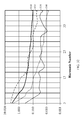
- FIG. 6 illustrates a typical charging process of a Li-Ion battery that may be representative for a battery that may be used in a BEV.
- the graph illustrates charge current versus charge time, cell voltage, and charge capacity.
- substantially constant current may be applied to the battery as the charge capacity is increasing at a relatively high rate.
- a substantially constant voltage may be applied as the charge capacity nears full charge.
- FIG. 6 illustrates an example charge scenario for charging a battery at its rated capacity (often referred to as 1C).
- Other fast charge scenarios may be used, such as rates faster than 1C (e.g., 2C, 3C, etc).
- FIG. 7 illustrates examples of charging times for a battery that may be used in a BEV.
- a stored energy of 25 kWh is shown as one example of a charge capacity for a typical battery in a BEV.
- the charge time to full capacity may be as low as about 1.25 hours with a high delivery capability of about 21 kW, about 3.5 hours for an accelerated delivery capability of about 7 kW, about 8.5 hours for a normal delivery capability of about 3 kW, and about 12.5 hours for a domestic delivery capability of about 2 kW.
- FIG. 7 is intended as an example only to show ranges of charging times and how they may be adapted to wireless power delivery capabilities.
- FIG. 8 illustrates a frequency spectrum showing various frequencies that may be available and suitable for wireless charging of BEVs.
- Some potential frequency ranges for wireless high power transfer to BEVs include: VLF in a 3 kHz to 30 kHz band, lower LF in a 30 kHz to 150 kHz band (for ISM-like applications) with some exclusions, HF 6.78 MHz (ITU-R ISM-Band 6.765 - 6.795 MHz), , HF 13.56 MHz (ITU-R ISM-Band 13.553 - 13.567), and HF 27.12 MHz (ITU-R ISM-Band 26.957 - 27.283).
- FIG. 9 illustrates some possible frequencies and transmission distances that may be useful in wireless charging of BEVs.
- Some example transmission distances that may be useful for BEV wireless charging are about 30 mm, about 75 mm, and about 150 mm.
- Some exemplary frequencies may be about 27 kHz in the VLF band and about 135 kHz in the LF band.
- Wireless power frequencies may interfere with frequencies used for other applications.
- VLF and LF are: frequencies for radio clocks, frequencies for LW AM broadcasts and other radio services, cross-coupling to ISDN/ADSL and ISDN/xDSL communication channels, electronic vehicle immobilization systems, RFID (Radio Frequency Identification) systems, EAS (Electronic Article Surveillance) systems, onsite paging, Low Voltage PLC systems, medical implants (cardiac pacemakers, etc.), audio systems and acoustic emission perceivable by humans and animals.
- RFID Radio Frequency Identification
- EAS Electronic Article Surveillance
- Some non-limiting examples where coexistence may be an issue for HF frequencies are industrial, scientific and medical (ISM) radio bands, such as: 6.78 MHz for remote control applications and RFID in FDX or HDX mode with continuous energy transfer; 13.56 MHz for RFID in FDX or HDX mode with continuous energy transfer as well as portable device wireless power; and 27.12 MHz for Railway applications (Eurobalise 27.095 MHz), Citizen band radio, and remote control (e.g., models, toys, garage door, computer mouse, etc.).
- ISM industrial, scientific and medical
- FIG. 10 illustrates transmit and receive loop antennas showing field strength relative to radius of the antennas.
- Antenna structures with a radius larger or smaller than an optimum radius generate higher field strength in the vicinity of the antenna for a given transferred power.
- H-field strength increases linearly with increasing power transfer distance and for a given transferred power provided that the antenna radius is proportionally increased thus always optimum.
- FIGS. 11A and 11B illustrate electromagnetic fields around a loop antenna and accompanying ferrite backing.
- a transmit antenna includes a wire loop 1130, which may comprise a multi-turn wire loop, and a ferrite backing 1120 and a receive antenna includes a wire loop 1180 and a ferrite backing 1170.
- a ferrite backing may be useful for intensifying the magnetic field 1140 in the space between the antennas thus for enhanced coupling.
- FIG. 11A if the separation between the antenna coils 1130 and 1180 and the ferrite backings 1120 and 1170 is reduced to 0 cm, the coupling coefficient between the transmit antenna and receive antenna decreases slightly.
- FIG. 11B illustrates a small separation between the antenna coils 1130 and 1180 and the ferrite backings 1120 and 1170.
- FIG. 11B illustrates a reduced spacing between the antenna coils 1130 and 1180 and their respective ferrite backings 1120 and 1170. For smaller transmission distances (e.g., 3 cm), the performance gain of ferrite backing may be less because the coupling coefficient is very high already.
- FIG. 12 is a graph illustrating possible inductance values for various thicknesses of a ferrite backing as part of a wireless power antenna.
- the ferrite backing is about 0.5 cm from the coil. It can be seen that inductance does not change considerably (i.e., about 5%) with a thickness change for the ferrite backing between about 5 mm and 10 mm.
- FIG. 13 is a graph illustrating possible ferrite loss values for various thicknesses of a ferrite backing as part of a wireless power antenna.
- the ferrite backing is about 0.5 cm from the coil. It can be seen that losses increase rapidly (i.e., about 185%) with a thickness change for the ferrite backing between about 5 mm and 10 mm. The resulting loss may decrease the Q factor. As a result, a trade-off may need to be made between performance relative to considerations such as volume, weight, and cost.
- FIG. 14 shows a simplified diagram of a replaceable battery disposed in a battery electric vehicle (BEV) 220.
- BEV battery electric vehicle
- the BEV side of the wireless energy transfer system is an integral part of the vehicles battery unit 222.
- Present movements towards standardized EV batteries may enable easy and fast replacement in so-called battery swapping (or switching) stations.
- the shape and placement of the battery unit 222 are illustrative of one exemplary embodiment. Many other configurations are possible.
- the bulk of the battery may be below the rear seat.
- the low battery position may be useful for a battery unit that integrates a wireless power interface and that can receive power from a charger embedded in the ground.
- Fast battery replacement will likely continue to coexist with corded and wireless BEV charging and will not totally supersede any alternative charging solution (e.g., wireless charging).
- any alternative charging solution e.g., wireless charging.
- motorists can get a fully recharged battery perhaps in less than a minute (faster than refueling in a conventional gas stations), while corded and wireless charging will be the solution at home and for opportunistic charging in public and private parking lots to increase vehicles autonomy time.
- the EV replaceable battery unit 222 is accommodated in a specially designed battery compartment 224.
- the battery unit 222 also provides a wireless power interface 226, which may integrate the entire BEV sided wireless power subsystem comprising the resonant magnetic antenna, power conversion and other control and communications functions needed for efficient and safe wireless energy transfer between a ground embedded charging base (CB) and the Electric Vehicle (EV) battery.
- CB ground embedded charging base
- EV Electric Vehicle
- the BEV antenna may be integrated flush with a bottom side of battery unit 222 (vehicle body) so that there are no protrusive parts and so that the specified ground-to-vehicle body clearance can be maintained.
- This configuration may require some room in the battery unit dedicated to the wireless power subsystem.
- the CB antenna and the BEV antenna are fixed in position and the antennas are brought within a near-field coupling region by overall placement of the BEV relative to the CB.
- the distance between the charging base antenna and the BEV antenna may need to be reduced to improve magnetic coupling.
- the CB antenna and the BEV antenna may be deployable moveable to bring them into better alignment.
- FIG. 14 Also illustrated in FIG. 14 is a battery unit 222 that is completely sealed and that provides contactless power and communications interfaces 226,228.
- a conceptual block diagram of this exemplary embodiment is illustrated in FIG. 16 .
- FIGS. 15A and 15B are more detailed diagrams of a loop antenna and ferrite material placement relative to a battery.
- the battery unit includes a non-deployable BEV antenna module as part of the wireless power interface.
- a conductive shielding 232 e.g., a copper sheet
- FIG. 15A shows a fully ferrite embedded antenna coil 236.
- the coil 236 itself may be made, for example only, of stranded Litz wire.
- FIG. 15B shows an optimally dimensioned ferrite plate (i.e., ferrite backing) to enhance coupling and to reduce eddy currents (heat dissipation) in the conductive shield 232.
- the coil may be fully embedded in a non-conducting non-magnetic (e.g. plastic) material 234. There may be a separation between coil and ferrite plate in general, as the result of an optimum trade-off between magnetic coupling and ferrite hysteresis losses.
- FIG. 16 is a simplified block diagram of portions of a battery system 250 in a BEV equipped to receive wireless power.
- This exemplary embodiment illustrates wireless power interfaces that may be used between an EV system 252, a battery subsystem 254, and the wireless charging interface to a CB (not shown).
- the battery subsystem 254 provides for both energy transfer and communications with a wireless interface between the EV and the battery subsystem 254, which enables a completely contactless, closed, and sealed battery subsystem 254.
- the interface may include all the required functionality for bidirectional (two-way) wireless energy transfer, power conversion, control, battery management, and communications.
- FIG. 16 shows a generic concept.
- the wireless power antenna 260 and the communications antenna may be combined to a single antenna. This may also apply to the battery-to-EV wireless interface 262.
- the power conversion (LF/DC) unit 264 converts wireless power received from the CB to a DC signal to charge the EV battery 266.
- a power conversion (DC/LF) 268 supplies power from the EV battery 266 to a wireless power interface 270 between the battery subsystem 254 and the EV system 252.
- a battery management unit 272 may be included to manage EV battery charging, control of the power conversion units (LF/DC and DC/LF), as well as a wireless communication interface.
- a wireless antenna 274 receives power from antenna 276 and a LF/DC power conversion unit 278 may supply a DC signal to a super capacitor buffer 280.
- LF/DC power conversion unit 278 may supply a DC signal directly to the EV power supply interface 282.
- a contactless interface may not be capable of providing the high battery peak current required by the vehicles drive train e.g., during acceleration.
- an additional super capacitor buffer may be employed.
- An EV electrical system control unit 284 may be included to manage control of the power conversion unit (LF/DC) 278, charging of the super capacitor buffer 280, as well as a wireless communication interface 262 to the EV and the battery subsystem 254. Furthermore, it is noted that V2G capabilities, as described above, may apply to the concepts described with reference to, and illustrated in, FIG. 16 .
- Wireless power delivery to BEVs may require a significant amount of power. As a result, lower frequencies may be more appropriate for transmission of the higher power. Power conversion electronics may be more available at the lower frequencies of VLF and LF.
- the following discussions will refer to LF frequencies for clarity and brevity. However, unless other wise noted, the following discussion may also be applicable to VLF or frequencies above LF.
- a reflected impedance is seen by the transmitter (power converter) and a DC resistance is seen at the DC power supply terminals.
- FIGS. 17A and 17B illustrate a simplified circuit diagram and a waveform, respectively, for a power conversion system using a half-bridge series resonant circuit.
- the half-bridge circuit 300 in FIG. 17A illustrates a transmit power conversion circuit that converts DC power with a voltage V DC and current I DC to LF power at a suitable operating frequency to supply a series resonant antenna circuit (L 1 , C 1 ) with voltage V 1 and current I 1 , and which presents a load resistance R 1L at fundamental frequency.
- This load resistance represents the real part of the impedance 'reflected' by the power receiver (not shown in FIG. 17A ).
- the half bridge power conversion circuit 300 presents an input resistance R DC .
- Capacitor C DC assists in buffering DC input power and stabilizing the input voltage and to block switching frequency signals from propagating into the DC supply.
- the waveforms in FIG. 17B illustrate the switching voltage V 1 (t) that is substantially square wave as well as its DC component and fundamental frequency component V 1,0 (t) + V DC /2. It can be shown that the apparent resistance R DC at DC input of the half bridge power conversion is about four times the resistance R 1L .
- FIGS. 18A and 18B illustrate a simplified circuit diagram and a waveform, respectively, for a power conversion system using a full H-bridge series resonant circuit.
- the full-bridge circuit 310 in FIG. 18A illustrates a transmit power conversion circuit that converts DC power with a voltage V DC and current I DC to LF power at a suitable operating frequency to supply a series resonant antenna circuit (L 1 , C 1 ) with voltage V 1 and current I 1 , and which presents a load resistance R 1L at fundamental frequency.
- This load resistance represents the real part of the impedance 'reflected' by the power receiver (not shown in FIG. 17A ).
- the full bridge power conversion circuit presents an input resistance R DC .
- Capacitor C DC assists in buffering DC input power and stabilizing the input voltage and to block switching frequency signals from propagating into the DC supply.
- the waveforms in FIG. 18B illustrate the switching voltage V 1 (t) that is substantially square wave as well as its fundamental frequency component V 1,0 (t). (There is ideally no DC component). It can be shown that the apparent resistance R DC at DC input of the full bridge power conversion is about equal to the resistance R 1L .
- FIG. 19 is a simplified circuit diagram for a power conversion system to illustrate reciprocal operation of the transmit power conversion as a receive power conversion that acts as a half bridge rectifier.
- the half-bridge rectifier circuit 320 in FIG. 19 illustrates a receive power conversion circuit for generating a DC power with a voltage V DC,L and DC current I DC,L when connected to a load resistance R DC,L .
- the two solid-state switches S 2 and S 2 are synchronously switching with the frequency and in phase of the power received by series resonant antenna circuit (L 2 , C 2 ) with a voltage V 2 and current I 2 .
- the voltage source with voltage V ind,2 represents the voltage induced by the transmitter.
- the solid-state switches may be actively controlled, whereas in other exemplary embodiments, they may simply be diodes.
- Capacitor C DC assists in the filtering and buffering of the rectified LF power. It can be shown that for a half bridge topology, the apparent load resistance R 2L as seen by the receive resonant antenna at fundamental frequency is about four times lower than the DC load resistance R DC,L connected to the DC output of the receive power conversion.
- an exemplary embodiment may also include a full H bridge topology (not shown) and would have an impedance transformation ratio R 2L -to-R DC,L of about one-to-one.
- FIG. 20 is a simplified equivalent circuit of a wireless power system illustrating some parameters that may be varied in development of an efficient wireless power system.
- the LF power source providing the LF signal at voltage V S and its equivalent source impedance R S are substantially fixed (given). These source impedance may represent any losses produced in transmit power conversion circuit elements and any matching or filtering circuitry prior to the resonant transmit antenna.
- the load resistance R L and voltage V L , as well as the series resistance R r are substantially fixed (given).
- the series resistance R r may represent any losses produced in receive power conversion circuit elements and any matching or filtering circuitry post to the resonant receive antenna.
- the unloaded Q-factor of the transmit antenna coil Q 1 and the unloaded Q-factor of the receive antenna coil Q 2 , as well as the coupling factor (k) therebetween can be considered as fixed (given) and the other circuit elements are adapted to optimize power transfer based on given Q 1 , Q 2 , and the coupling factor (k).
- a sensible approach to this design problem first specifies the required source and load voltages (in particular the required voltage transfer ratio ⁇ V,e ) and target Q-factors Q 1 and Q 2 for the antenna/coils. Optimization is then performed by varying antenna inductances L 1 and L 2 , series resonant loss resistance R 1 and R 2 , series resonant capacitors C 1 and C 2 , and combinations thereof for maximum transfer efficiency while maintaining specified antenna unloaded Q-factors Q 1 and Q 2 .
- the voltage transfer ratio is determined by the network symmetry and becomes: ⁇ V , e ⁇ k Q tot 1 + k Q tot ⁇ ⁇ M , e , max where: Q tot ⁇ Q ⁇ 0 ⁇ L opt ⁇ 0 ⁇ L opt + Q R S and: ⁇ M,e,max is the maximum achievable end-to-end efficiency.
- FIG. 21 illustrates an equivalent circuit that may be useful to model various parameters of a wireless power system. If optimum inductance is unrealizable at a specified Q (e.g., due to voltage or current constraints), a specific matching circuit may be needed, which is normally the case in a moderately or weakly coupled regime or for particular values of R L . As shown in FIG. 21 , a matching circuit can be represented using ideal transformers (2110 on the transmit side and 2120 on the receive side). Such transformation can be accomplished in many different ways, such as, for example, using shunt capacitance to source and/or load, parallel resonance, inductive coupling loops, etc.
- Optimum matching may be generally determined by the required overall voltage transfer ratio, and the magnetic links internal and external losses (e.g., due to power conversion). In strongly coupled regimes, matching can normally be achieved by choosing a pair of optimum antenna inductance (or L-C ratio) at a specified Q factor. Matching by L-C ratio, if possible, may be preferable as this method is simplest and does not introduce additional (lossy) and expensive components.
- the circuitry for transmit and/or receive power conversion may be used to perform impedance transformation to adapt apparent source resistance and/or load resistance to the optimum value. However this may add extra losses, which may unfavorably alter the ratio R r to R L . As a result, such methods may best be used when coupling is variable or the load resistance changes dynamically and considerably.
- FIG. 22 is a simplified block diagram of a wireless power system 400 for a BEV illustrating some basic components of the system.
- AC supply voltages may be referred to with the European standards of about 230 volts AC at about 50 Hz. However, supply voltages may be DC, and other AC formats such as the United States standards of 110 volts AC at 60 Hz and 220 volts AC at 60 Hz.
- the following descriptions will refer to LF frequencies for clarity and brevity. However, unless otherwise noted, the following discussion may also be applicable to VLF or frequencies above LF.
- the DC/LF converter 402 changes the intermediate DC voltage to a frequency in the LF range for driving the transmit antenna of the wireless power link.
- the AC/DC converter 404 changes the AC supply voltage to an intermediate DC voltage and a DC/LF converter 406 changes the intermediate DC voltage to a frequency in the LF range for driving the transmit antenna of the wireless power link.
- a receive antenna 410 couples with the transmit antenna 408 when it is in the coupling-mode region of the transmit antenna and resonates at substantially the same frequency as the transmit antenna.
- a LF/DC converter 412 changes the LF signal from the receive antenna 410 to a DC signal for charging the BEV battery 414.
- the power available (P L,nom ) may be about 2 kW
- the voltage available (V L,nom ) may be about 400 V DC
- the current available (I L,nom ) may be about 5 amps.
- the impedance seen by the LF/DC converter 412 in this case may be about 80 ⁇ .
- FIG. 23 is a simplified circuit diagram of a wireless power system 420 for a BEV illustrating some possible circuits and waveforms for generating wireless power signals.
- diodes D 11 , D 11' , D 12 , and D 12 along with capacitor C DC,1 form the AC/DC conversion to the intermediate DC voltage on the transmit side.
- Transistors Q 14 , Q 14' , Q 24 , and Q 24' create the DC/LF conversion using a pulse-width-modulation (PWM) approach to control switching of the transistors.
- Capacitor C 1 and inductance L 1 represent the series resonant transmit antenna.
- PWM pulse-width-modulation
- the PWM control may be set at about a 50% duty cycle to ensure that there is switching only when resonant antenna current I 1 (t) passes zero.
- a receive antenna L 2 couples with the transmit antenna L 1 when it is in the coupling-mode region of the transmit antenna providing a mutual inductance M and resonates at substantially the same frequency as the transmit antenna.
- diodes D 21 , D 21' , D 22 , and D 22' along with capacitor C DC,2 form the LF/DC converter and rectify the LF signal from the receive antenna to create the DC voltage, and current, power, when loaded by a corresponding DC resistance as shown in FIG. 22 .
- power control may also be needed if different BEV classes with different charging power requirements have to be supported by the same charging base.
- power control may be useful for reasons, such as, for example, to regulate charging current, to ramp up and ramp down power smoothly, and to operate the system in a low power mode for antenna alignment, to emit a low power (beacon) signal that can be used to guide BEVs to a charging spot (guidance system), and/or to align the wireless power antennas of the charging base and/or the BEV, and other tuning and testing purposes.
- FIG. 24 is a simplified block diagram of a wireless power system 430 for a BEV illustrating a variable power control block for converting DC power to wireless power at a suitable frequency.
- the elements in FIG. 24 are similar to the elements in FIG. 22 except that the DC/LF converter 432 on the transmit side is now variable to accomplish power control.
- FIGS. 25A-25G are simplified block diagrams of a wireless power system for a BEV illustrating various exemplary embodiments of the variable power control block of FIG. 24 .
- an additional DC/DC converter 442 (also referred to herein as a DC-to-DC converter) is placed between the AC/DC converter 444 (also referred to herein as a AC-to-DC converter) and the DC/LF converter 446 (also referred to herein as a DC-to-LF converter).
- this DC/DC converter 442 may be a buck converter or a boost converter for modifying the voltage level of the intermediate DC supply of the DC/LF converter 446.
- the DC/LF converter 446 is driven at a 50% duty cycle to ensure zero current switching as explained above with reference to FIG. 23 .
- the DC/LF converter 456 is modified from a 50% duty cycle to a lower or higher duty cycle to adjust the amount of power delivered to the transmit antenna.
- a duty cycle other than 50% may compromise overall efficiency somewhat, because zero current switching cannot be maintained, but it is a simple means for adjusting power levels without using additional circuitry.
- the operating frequency is offset from resonance by changing the frequency of the PWM control signal in the DC/LF converter 466 relative to the resonant frequency of the transmit and receive antenna. This offsetting of the PWM frequency relative to the resonant frequency will reduce the amount of transmitted power, but will also reduce link efficiency as zero-current switching cannot be maintained in an off-resonance mode.
- the resonant frequency of the antenna is detuned by adding variable capacitance to the resonant transmit antenna circuit, which will reduce the amount of power transferred between the transmit antenna and the receive antenna.
- tuning may be accomplished using a capacitor bank 470 with active switching components (as shown below with reference to FIG. 53 ) or by switch-controlled capacitance/inductance techniques.
- the DC/LF converter 476 topology is reconfigured from a full-bridge rectifier to a half-bridge rectifier when power has to be reduced or vice versa when maximum power needs to be restored.
- This method comes almost for free as it does not require additional circuitry and can be accomplished solely by changing the PWM driving waveforms. This method however only allows for a two level (coarse) power control.
- the DC/LF converter 486 excites the resonant transmit antenna with one of the harmonic components of its drive waveform. In other words, the DC/LF converter 486 operates at a subharmonic frequency of the actual transmission frequency. This method allows power to be changed in a number of levels according to the levels contained in a harmonics series.
- the AC/DC converter 490 providing DC supply power to the DC/LF converter 496 may be intermittently operated with a duty cycle adjusted to the average power (battery charge current) demand.
- This average power control method in conjunction with battery charging is also known as pulse charging.
- FIGS. 25A-25G may be used in combination to form additional means for power control and creating means for both coarse and fine adjustments.
- FIG. 26 is a simplified block diagram of a wireless power system 500 for a BEV illustrating that the means and methods for variable power control shown in FIGS 24-25G may also be applicable to load adaptation in the BEV.
- Load adaptation is needed to maintain the load resistance as seen by the wireless power link and in particular by the resonant receive antenna at an optimum value to operate the link efficiently. This load resistance may change e.g. if battery charging current is reduced and may be a direct consequence of transmit side power control.
- the variable LF/DC converter 502 on the receive side may be configured in a manner similar to those described above in FIGS. 25A-25G except that these means are used to regulate (transform) the load impedance as seen by the receive antenna, rather than to control power.
- Transmit side power control and receive side load adaptation may be considered as transformers whose transformation ratios (n TX :1) and (1:n RX ), respectively, are adjustable. This contemplation shows their relationship. For example, if n TX is increased to reduce power then n RX may have to be increased by the same amount to readapt to the load. (Note that the load voltage V L may be substantially constant, independently on n RX , since the load is a battery that is substantially a voltage source. Therefore power control and corresponding load adaptation cannot be simply explained as a mean to maintain a constant output voltage, thus not trivial.)
- FIG. 27 is a simplified block diagram of a wireless power system 520 for a BEV illustrating a communication channel between the BEV and the charging base (CB) that may be present in some embodiments of the invention.
- the BEV communication unit or other units in the BEV side, may sense values of voltage and current to the BEV battery and provide feedback through the BEV communication unit to the CB communication unit. Based on the values sensed, both the variable DC/LF converter in the transmit (CB) side and the variable LF/DC converter in the receive (BEV) side may adjust transformation ratios by any of the means discussed above to optimize power transfer or otherwise adjust power transfer.
- FIG. 28 is a simplified block diagram of a wireless power system 540 for a BEV illustrating a variable power control block 542 and a power factor correction block 544 for converting a DC signal to a LF signal at a suitable frequency for wireless power.
- Power factor correction may be defined as a reduction of harmonic content in currents of the AC supply system. Reducing current harmonics content may be a requirement for compliance of electric appliances consuming power above a specified limit according to international or national standards (e.g., IEC 61000-3-2). Reducing AC current harmonics helps energy suppliers to reduce excessive power losses in the power grid and to maintain mains voltage substantially sinusoidal.
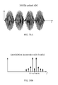
- FIGS. 29A-29C illustrate a conventional rectifier circuit 560, typical voltage and current waveforms, and a current harmonics spectrum, respectively, before power factor correction has been included.
- a conventional full-bridge rectifier 560 is illustrated with four diodes and a load capacitor on the output V DC .
- the input voltages and currents are labeled as V AC (t) and I AC (t), respectively.
- FIG. 29B illustrates the voltage and current waveforms for the conventional full-bridge rectifier.
- the voltage curve is a sine wave; however, the current curve has spikes where the diodes switch to a conducting mode when recharging the DC smoothing capacitor in each AC cycle.
- these current spikes will have highest level at fundamental frequency, but they will also produce a number of harmonic signals, which can have quite high amplitudes as shown in FIG. 29C .
- the input resistance as seen by the AC power supply system is time variant (R AC (t)) and may change considerably and periodically with the AC frequency.
- FIG. 30 is a simplified block diagram of a rectifier 570 with a passive power factor correction block 572.
- the conventional rectifier 570 is followed by a passive device 572 that is a large inductor inserted in series between the rectifier and the smoothing capacitor.
- the inductor acts as a choke that will somewhat reduce harmonic content in the AC input current.
- the passive choke can be very bulky and introduces a voltage drop on the DC output, thus losses.
- FIGS. 31A-31D illustrate a simplified schematic diagram, voltage and current waveforms, a correction function, and a harmonics spectrum, respectively, with active power factor correction.
- FIG. 31A illustrates an active power factor correction module (PFC) 580 inserted after the conventional rectifier 582.
- the active PFC 580 may be configured as a boost converter operated with a time-variant AC periodic transformation ratio M(t) as shown in FIG. 31D , which creates and presents a variable impedance to the rectifier.
- This variable impedance function may be configured such that the resistance as seen at the rectifiers input (R AC (t)) and that is normally time-variant becomes substantially constant.
- the instantaneous resistance seen at the AC input terminal is substantially constant and the voltage and current waveforms both maintain a substantially sinusoidal shape as shown in FIG. 31B , thus low harmonic content in the AC input current as shown in FIG. 31C .
- FIG. 32 is a graph illustrating the harmonics present in a rectifier without power factor correction, a rectifier with passive power factor correction and a rectifier with active power factor correction.
- Curve 3210 illustrates a maximum limit that may be acceptable for harmonic content according to some standards.
- Curve 3220 illustrates harmonics for a full-bridge rectifier with no PFC.
- Curve 3230 illustrates the lower harmonic values that can be produced for the full-bridge rectifier followed by the simple choke as illustrated in FIG. 30 .
- Curve 3240 illustrates the even lower harmonic levels that can be achieved with a full-bridge rectifier followed by an active PFC module as illustrated in FIG. 31A .
- FIG. 33 is a simplified block diagram of a wireless power system 800 for a BEV illustrating a variant that does not perform power factor correction but rather relies on PFC that may exist as part of the BEV's conductive charging system.
- This variant assumes that the wireless power system connects to the BEVs conductive charging interface 802 in an alternative manner. It can also be assumed that wireless (cordless) charging will not supersede corded charging via the standardized charging plug, so there will always be a conductive charging interface (CCI).
- a solid state switch or relay 804 may be included to switch between cordless and corded charging. Corded charging may directly plug into the AC supply system or may use other means for charging the BEV with a wired connection.
- a PFC module 806 on the receive side may already be available for reducing harmonics at the conductive charge interface that may have to comply to same standards.
- the PFC module 806 of the BEV charging system can be used to control harmonics back through the wireless power link to the charging base such that there may be no need for transmit-side PFC.
- the wireless power transmit waveform will be no more constant envelope as shown and explained in the following.
- the AC/DC converter 808 on the BEV charging system would be in place to support the AC signal from the CCI.
- the DC signal from the LF/DC converter 810 can pass directly through the AC/DC converter 808 as a DC signal. Therefore, there may be no need to convert the LF from the wireless power link to an AC compatible with the CCI and an existing and simpler LF/DC converter 810 can be used.
- FIG. 34 is a simplified circuit diagram of a wireless power system 820 for a BEV illustrating some possible circuits and waveforms performing inherent power factor correction at AC supply input.
- Diodes D 11 , D 11' , D 12 , and D 12' rectify the AC input power to generate a substantially unfiltered DC power to supply the DC/LF converter.
- the DC waveform may be considered as rectified half waves or AC halfwave modulated DC.
- the output of the DC/LF converter and the transmit antenna (L 1 ) current will be AC halfwave modulated too as shown in FIG. 34 .
- An inductor L DC may be used in combination with capacitor C DC,1 to lightly smooth the intermediate DC supply voltage and to block the LF that may be generated by the PWM circuits from propagating back in to the AC supply system in the sense of EMI filtering.
- the low frequency PWM drive signals are shown as square waves controlling the switching transistors Q 14 , Q 14' , Q 24 , and Q 24' configured as full bridge such that the unfiltered DC supply is modulated onto the LF to produce the modulated AC signal at the transmit antenna.
- diodes D 21 , D 21' , D 22 and D 22' rectify the received modulated AC signal to produce a DC output that AC modulated too.
- Capacitor C DC,2 serves to lightly smooth the DC output and to remove the LF content at the BEV charging interface in the sense of EMI filtering. Since this wireless power system will be transparent meaning that load resistance as seen at the CCI will be reflected back to its AC supply input, the instantaneous resistance as seen at the AC input of the wireless power system will also be substantially constant and thus low harmonic level.
- FIG. 35A and 35B are graphs illustrating transmit waveforms in the time domain and frequency domain, respectively, that would be generated by the exemplary embodiment of FIG. 34 with non-filtered DC supplied to the low frequency (LF) stage.
- FIG. 35A shows transmit antenna current in the time domain as a 100 Hz pulsed AM signal.
- FIG. 35B shows the transmit signal in the frequency domain to show the fundamental frequency at about 100 Hz and the harmonic side bands on either side of the fundamental frequency.
- FIG. 36 is a simplified block diagram illustrating a bidirectional wireless power system 840 including a bidirectional wireless power transceiver for a BEV.
- Bidirectional or two-way energy transfer means that energy can be transferred either from charging base towards BEV or from BEV towards charging base which is to the power grid.
- bidirectional wireless power transfer will be required to realize the V2G (Vehicle-to-Grid) functionality that may become an important feature in future smart grids in which BEVs temporarily connected to the grid will be used as distributed energy storage devices 854 e.g. to compensate for fluctuations in distributed renewable energy production and to locally stabilize the power grid.
- V2G Vehicle-to-Grid
- exemplary embodiments may be configured with the CB side AC/DC converter 842, the DC/LF converter 846 as bidirectional power converters.
- the LF/DC converter, the AC/DC converter, and the PFC 850 on the BEV side may be configured as bidirectional power converters.
- the exemplary embodiment of FIG. 36 is symmetrical and capable of transferring and controlling power in both directions across the wireless power link.
- the AC/DC converter 848 on the BEV charging system would be in place to support the AC signal from the CCI 852.
- the DC signal from the LF/DC converter 846 can pass directly through the AC/DC converter 848 as a DC signal, as was explained above with reference to FIG. 33 . Therefore, in a bidirectional system, some exemplary embodiments may include an AC/DC conversion on the BEV side. In other exemplary embodiments, the AC/DC converter 848 on the BEV side, when operating in the reverse direction, would convert to a CCI frequency or LF, depending on which interface was selected.
- FIG. 37 is a simplified circuit diagram of a wireless power system 860 for a BEV illustrating a symmetric topology for bidirectional wireless power transfer with an intermediate unfiltered DC supply.
- the wireless power system interfaces at AC at both of its interfaces (CB side and BEV side).
- CB side and BEV side On both the CB side and the BEV there is a cascade of full bridge PWM modules that may either act as AC/DC converter (rectifier) or DC/AC converter (inverter, which may also be referred to herein as DC-to-AC converters) or as LF/DC (rectifiers) or DC/LF converters (inverters), respectively with substantially unfiltered intermediate DC that assumes light smoothing as described with reference to FIG. 34 .
- a converter operating as either digital-to-analog or analog-to-digital may be may be referred to herein as a DC/AC converter.
- DC/AC DC/LF
- DC/LF DC/AC
- the AC/DC converter is actually operating as a rectifier instead of as an inverter.
- an AC/DC converter on the BEV side is operating in transmit mode
- the AC/DC converter is actually operating as an inverter instead of as a rectifier.
- bridge circuits namely full-bridge and half-bridge circuits when configured for bidirectional power transfer, operates as both a rectifier and as an inverter depending upon the direction of power transmission. Therefore, bidirectional full-bridge circuits and half-bridge circuits may be synonymously referred to herein as full-bridge inverter/rectifier and half-bridge inverter/rectifier circuits.
- the AC input on the far left is rectified by the AC/DC converter (first full bridge Q 11 , Q 11' , Q 12 , Q 12' ) that is operated as a synchronous rectifier to produce an unfiltered DC supply.
- Synchronous rectification means that once in synchronous mode rectification is performed by the active switches (transistors) rather than by the passive diodes that are always in parallel also to protect active switches from reverse polarization.
- the use of active switching which is here needed to operate converters in both directions (i.e., bidirectional power converters) may bring the additional advantage of lower switching losses thus higher efficiency.
- the unfiltered DC supplies the following full bridge (Q 13 , Q 13' , Q 14 , Q 14' ) that is the DC/LF converter and that drives AC modulated LF current into the resonant antenna of the CB.
- the third full bridge (Q 21 , Q 21' , Q 22 , Q 22' ) synchronously rectifies received LF power to AC-modulated DC power and the fourth full bridge (Q 23 , Q 23' , Q 24 , Q 24' ) reconverts it to AC power.
- there may be a DC supply at CB side input in this case the first full bridge would be operated in a static mode without switching. The same apply to the fourth bridge if the BEV side did accept DC power.
- FIG. 38 is a simplified circuit diagram of a wireless power system 870 for a BEV illustrating another symmetric topology for wireless power transfer without an intermediate unfiltered DC supply and based on a frequency mixing approach.
- the exemplary embodiment of FIG. 38 uses a fully symmetric full bridge topology consisting of four bidirectional active switch cells. In transmit mode, this topology may operate as AC/LF up-converter which is actually a Double Side Band (DSB) modulator or in receive mode as LF/AC down-converter which is a synchronous DSB demodulator to convert the received LF input power into the required AC power (e.g. 50 Hz).
- DSB Double Side Band
- LF/AC down-converter which is a synchronous DSB demodulator to convert the received LF input power into the required AC power (e.g. 50 Hz).
- These circuits may also apply if one or both interfaces of the wireless power system was a DC interface.
- transmission from the CB to the BEV proceeds from an AC input on the left side through the circuitry on the CB side acting as a DSB modulator, to the CB antenna, to the BEV antenna, and through the circuitry on the BEV side acting as a demodulator to create a AC or DC output power on the right side.
- transmission from the BEV to the CB proceeds from an AC or DC input on the right side through the circuitry on the BEV side acting as a DSB modulator, to the BEV antenna, to the CB antenna, and through the circuitry on the CB side acting as a demodulator to create an AC or DC output power on the left side.
- Conversion from a modulator function to a demodulator function may be accomplished with a bidirectional switch cell including two transistors in anti-parallel.
- the bidirectional switch cell On the BEV side, the bidirectional switch cell includes transistor Q 21 with a diode in series therewith and cross-coupled transistor Q 22 with a diode in series therewith.
- the bidirectional switch cell On the CB side, the bidirectional switch cell includes transistor Q 13 with a diode in series therewith and cross-coupled transistor Q 14 with a diode in series therewith.
- FIG. 39A and 39B are graphs illustrating transmit waveforms in the time domain and frequency domain, respectively, with power conversion that is Double Side Band (DSB) modulated.
- the time domain illustrates that a 180° phase-shift exists on the signal from one AC half wave pulse to the next AC half wave pulse. This is well known as the waveform of a double tone signal.
- FIG. 39B in the frequency domain, a clean double-frequency spectrum is generated ideally with no spectral skirts (sidebands of 100 Hz harmonics) as it is the case for the approach shown in FIG. 37 .
- the DSB modulator approach is transparent in regards to load resistance, thus may be potentially suitable to make use of PFC that may already exist in the BEV charging system for reasons of compliance of the CCI.
- FIG. 40 is a simplified block diagram of a wireless power system 880 for a BEV illustrating an alternative approach to interface to the BEV charging system and that bypasses the BEV AC-to-DC converter to reduce the length of the power conversion chain thus likely increasing its end-to-end efficiency.
- This exemplary embodiment illustrates moving the charging mode switch 882 from the input of the AC/DC to the input of the PFC 884.
- the AC/DC converter 886 is between the CCI 888 and the switch 882 as opposed to the embodiment of FIG. 36 where the AC/DC converter is after the switch. This solution avoids conversion/re-conversion to/from AC on the wireless power side of the switch.
- FIG. 40 illustrates moving the charging mode switch 882 from the input of the AC/DC to the input of the PFC 884.
- the AC/DC converter 886 is between the CCI 888 and the switch 882 as opposed to the embodiment of FIG. 36 where the AC/DC converter is after the switch. This solution avoids conversion/re-conversion to/from AC on
- FIG. 40 may be more useful for a system that incorporates wireless charging from the start where the wireless power charging can be more optimally designed in and integration with the CCI.
- FIG. 41 is a simplified block diagram of a wireless power system 900 for a BEV illustrating that in some exemplary embodiments there may be no need for communication between the BEV charging system 902 and the BEV wireless power system 904.
- the wireless power system 904 may operate as a slave of the BEV charging system 902.
- the wireless power system 904 can work autonomously to a wide extent and inter-system communication may not be necessary as is illustrated by the X mark through the communication interface between the BEV charging system 902 and the BEV communication unit 906.
- This slave mode may be accomplished because, as explained earlier, wireless power transfer can be optimized by monitoring voltage and current at the receive side, at the transmit side, or a combination thereof and possibly communicating the measured information between the receive side and the transmit side.
- FIG. 42A is a simplified block diagram of a wireless power system 920 for a BEV illustrating coarse load adaptation.
- the LF/AC converter 922 can be modified between full-bridge rectification and half-bridge rectification.
- the DC-to-DC converter 924 can be modified by changing its load resistance.
- FIG. 42B is a simplified block diagram of a wireless power system 940 for a BEV illustrating fine load adaptation.
- the LF/AC converter 942 can be modified to adjust its transformation ratio in fine steps using the appropriate means already described above, such as, for example, detuning and PWM duty cycle adjustments.
- FIG. 43 is a simplified block diagram of a wireless power system 960 for a BEV illustrating reverse link load adaptation.
- the wireless power system can operate in a reverse link to move power from the BEV to the CB.
- a load adaptation and control strategy is defined in FIG. 43 for managing the reverse power flow.
- coarse adaptation can be performed by switching between full-bridge rectification and half-bridge rectification, except that the rectification switching may be performed on the CB side by the AC/LF converter 962 (operating in reverse direction as a LF/AC converter).
- Reverse power mode may detected when the resistance V S /I S at the BEV charging interface appears negative. It is assumed that BEV charging system 964 would limit output voltage V S so that V S would not increase infinitely (theoretically) if the load presented by the wireless power system 966 in reverse mode dropped off.
- V S As long as voltage V S remains above a defined threshold voltage V min , reverse power transmission into the AC mains (i.e., V L , I L , R L ) may be maintained at maximum (or at nominal rating). If V S drops below V min then the reverse power control may decrease power transmission until V S rises above the threshold again.
- AC-mains sided load adaptation may be performed in the charging base subsystem. Since AC mains will exhibit a quasi-constant voltage (behave like a voltage source), the load resistance as seen into the AC mains will depart from the optimum value when power decreases, requiring continuous load adaptation in CB subsystem.
- the BEV system may exhibit a different behavior and input resistance may be influenced by offered voltage.
- FIG. 44 is a flow diagram 1000 illustrating coarse load adaptation.
- FIG. 45 is a voltage versus current graph illustrating steps of a coarse load adaptation.
- FIG. 46 is a voltage versus current graph illustrating steps of a fine load adaptation.
- An optimum receiver load resistance may exist that maximizes transfer efficiency of the wireless power link.
- the function that maintains this optimum load resistance or transforms the actual load resistance as presented by the energy sink (e.g. the battery) to the optimum load resistance may be referred to as "load adaptation.”
- load adaptation may also be considered as the reverse function of power control. In wireless high power, load adaptation is of particular importance, as the magnetic link needs to operate at efficiencies close to 100%.
- the receiver may output a nominal voltage of about 230 V, a nominal current of about 10 A, providing a nominal power of about 2.3 kW into the optimum load of about 23 Ohms.
- BEV charging process enters a phase in which current decays slowly, which can be controlled using the DC/DC converter of the BEV charging system. Any current/charge power reduction will have an immediate effect at the output of the wireless power system.
- the wireless power system now decides to apply coarse load adaptation by reconfiguring the receive topology from full-bridge (i.e., transformation ratio about 1:1) to half-bridge (transformation ratio about 1:4).
- the optimum load resistance that needs to be targeted is, for example 92 Ohms instead of 23 Ohms.
- V L also will increase again to near the upper limit of the BEV DC/DC converter input range giving room for further demand reduction.
- the process of power throttling can now continue in the same manner however along the 92 Ohm load line until eventually the lower V L limit is reached.
- Fine load adaptation may be useful if the input voltage tolerance range of the BEV DC/DC converter was tight around the nominal V L .
- the transformation ratio (1:n) of the receiver would need to be steadily adapted using one of the methods described above, such as, for example, detuning, PWM duty cycle, etc.
- the wireless power system will respond by steadily incrementing the transformation ratio n such that V L can be maintained in a tight control band while the load resistance is maintained at optimum.
- the operating point will still track the optimum load line but the load line continuously changes its slope such that V L stays in the specified tight tolerance band.
- the wireless power system forces/stimulates the BEV DC/DC converter to perform fine load adaptation while the wireless power system itself only performs coarse load adaptation when the BEV DC/DC converter reaches its limits.
- the wireless power system does not (or only marginally) rely on the BEV DC/DC converter and performs load adaptation alone.
- FIG. 47 is a graph illustrating frequency versus current characteristics for various solid-state switches that may be used in exemplary embodiments.
- the semiconductor switches used for the power electronics stages in a wireless BEV charger may need to fulfil certain general requirements, such as, for example: a high operating voltage (e.g., > 500 V), a medium operating current (e.g., 10 A), a sufficient switching speed for VLF or LF frequencies, low on-state losses, and low switching losses.
- IGBTs Insulated Gate Bipolar Transistors
- MOSFETs Power Metal Oxide Field Effect Transistors
- IGBTs may be the device of choice for voltages > 1000 V and for low switching speeds in low voltage applications.
- MOSFETs may be the device of choice for switching speeds > 200 kHz and very low voltage applications.
- FIG. 48 illustrates normalized power as a function of transmitter duty cycle to show a significant range for the duty cycle.
- smooth power control would be dependent on the resolution available for the pulse width.
- PWM will likely be most effective for power control within the "interesting range" illustrated on FIG. 50 between about 0.25 and 0.5 for the duty cycle. Using PWM outside of this range may introduce additional harmonics and inefficiencies in the system. As a result, outside the "interesting range” other power control methods (e.g., half bridge and sub-harmonic drive) may be more effective.
- FIG. 49 is a simplified block diagram illustrating an exemplary embodiment of a wireless power system 1050 at high frequencies.
- Such high frequencies may be in the range of 3 MHz to 30 MHz as explained earlier and particularly the 13.56 MHz frequency used for RFID and Near Field Communication (NFC), the 6.78 MHz frequency and the 27.12 MHz frequency discussed earlier.
- the AC/DC converters and DC/HF converters can be configured to be bidirectional such that power can be transferred through the wireless power link from the CB to the BVE or from the BVE to the CB.
- FIG. 50 is a simplified circuit diagram of a wireless power system 1060 for a BEV illustrating an asymmetric Class E topology for wireless power transfer.
- the resonant antennas on both the CB side and the BEV side may include inductors (L M1 and L M2' , respectively) and capacitors (C S1 and C S2 , respectively) for impedance matching.
- transistor Q 1 may be used to generate the HF power.
- DC supply may be blocked for HF signals by capacitor C P1 and inductor L CH1 is part of the well known class E circuit.
- transistor Q 1 , capacitor C P1 and inductor L CH1 can act as a synchronous rectifier to reconvert HF power to DC power.
- Q 21 , capacitor C P2 and inductor L CH2 can perform the same HF power generation or HF rectification depending on whether the BEV is transmitting or receiving, respectively.
- FIG. 51 is a simplified circuit diagram of a wireless power system 1070 for a BEV illustrating a symmetric Class E topology for wireless power transfer at HF.
- the embodiment of FIG. 53 is similar to the embodiment of FIG. 52 except that it is fully symmetrical with duplicated circuitry on each side of the transmit antenna and duplicated circuitry on each side of the receive antenna. Since more active switches are involved this topology may have higher power capability, moreover, even harmonics in the antenna currents ideally cancel therefore simplifying additional harmonics filtering (not shown in FIG. 51 ).
- FIG. 52 is a simplified circuit diagram illustrating harmonics filtering in a wireless power system 1080 for a BEV operating at VLF, LF or even higher frequencies.
- a light harmonics filtering may suffice to achieve compliance with some standards.
- harmonics filtering may be performed by exemplary embodiments discussed above and additional harmonics filtering may be included as shown in FIG. 52 .
- the harmonics filtering for the case of a full bridge topology is illustrated as box 5210 on the CB side and box 5220 on the BEV side.
- the harmonics filter 5210 has a symmetric low pass structure and may include inductors L HF1 and L HF1' with a capacitor C HF1 therebetween.
- the harmonics filter 5220 has a symmetric low pass structure and may include inductors L HF2 and L HF2' with a capacitor C HF2 therebetween.
- FIG. 53 is a simplified circuit diagram illustrating resonance tuning in a wireless power system 1090 for a BEV that is based on a full bridge topology.
- the exemplary embodiment of FIG. 53 can be configured to make minor changes to the resonant frequency. These minor changes may be useful, for example, to compensate for some undesired de-tuning effect from other circuitry and to purposefully move the resonant frequency for power control.
- a main full-bridge topology is formed with solid-state switches S 11 , S 11' , S 12 , and S 12' and a main capacitor C 11 .
- a number of "mini" half bridges can be added with a corresponding capacitor to modify characteristics of the full-bridge by adding incremental amounts of capacitance. "n" half-bridges are illustrated in FIG.
- a first half-bridge includes solid-state switches S 13 , S 13' , and capacitor C 12 .
- a final half-bridge includes solid-state switches S 1n , S 1n' , and capacitor C 1n .
- a desired number of half-bridges can be synchronously switched with the full-bridge to add in incremental capacitances and modify the resonant frequency due to the additional capacitance. This tuning network applies to operating the full bridge in both transmit and receive (synchronous rectification) mode.
- DSP Digital Signal Processor
- ASIC Application Specific Integrated Circuit
- FPGA Field Programmable Gate Array
- a general purpose processor may be a microprocessor, but in the alternative, the processor may be any conventional processor, controller, microcontroller, or state machine.
- a processor may also be implemented as a combination of computing devices, e.g., a combination of a DSP and a microprocessor, a plurality of microprocessors, one or more microprocessors in conjunction with a DSP core, or any other such configuration.
- a software module may reside in Random Access Memory (RAM), flash memory, Read Only Memory (ROM), Electrically Programmable ROM (EPROM), Electrically Erasable Programmable ROM (EEPROM), registers, hard disk, a removable disk, a CD-ROM, or any other form of storage medium known in the art.
- An exemplary storage medium is coupled to the processor such that the processor can read information from, and write information to, the storage medium.
- the storage medium may be integral to the processor.
- the processor and the storage medium may reside in an ASIC.
- the ASIC may reside in a user terminal.
- the processor and the storage medium may reside as discrete components in a user terminal.
- the functions described may be implemented in hardware, software, firmware, or any combination thereof. If implemented in software, the functions may be stored on or transmitted over as one or more instructions or code on a computer-readable medium.
- Computer-readable media includes both computer storage media and communication media including any medium that facilitates transfer of a computer program from one place to another.
- a storage media may be any available media that can be accessed by a computer.
- such computer-readable media can comprise RAM, ROM, EEPROM, CD-ROM or other optical disk storage, magnetic disk storage or other magnetic storage devices, or any other medium that can be used to carry or store desired program code in the form of instructions or data structures and that can be accessed by a computer.
- any connection is properly termed a computer-readable medium.
- the software is transmitted from a website, server, or other remote source using a coaxial cable, fiber optic cable, twisted pair, digital subscriber line (DSL), or wireless technologies such as infrared, radio, and microwave
- the coaxial cable, fiber optic cable, twisted pair, DSL, or wireless technologies such as infrared, radio, and microwave are included in the definition of medium.
- Disk and disc includes compact disc (CD), laser disc, optical disc, digital versatile disc (DVD), floppy disk and blu-ray disc where disks usually reproduce data magnetically, while discs reproduce data optically with lasers. Combinations of the above should also be included within the scope of computer-readable media.
Abstract
Description
- This application claims priority under 35 U.S.C. § 119(e) to:
-
U.S. Provisional Patent Application 61/322,196 -
U.S. Provisional Patent Application 61/322,214 U.S. Provisional Patent Application 61/322,221 - This application is also related to the following applications, which are assigned to the assignee hereof and filed on even date herewith, the disclosures of which are incorporated herein in their entirety by reference:
U.S. Patent Application (Attorney Docket 101329) entitled "WIRELESS POWER ANTENNA ALIGNMENT ADJUSTMENT SYSTEM FOR VEHICLES" filed on April 8, 2011, the disclosure of which is hereby incorporated by reference in its entirety. - The present invention relates generally to wireless power transfer, and more specifically to devices, systems, and methods related to wireless power transfer to vehicles including batteries.
- Approaches are being developed that use over-the-air or wireless power transmission between a transmitter and a receiver coupled to the electronic device to be charged. Such approaches generally fall into two categories. One is based on the coupling of plane wave radiation (also called far-field radiation) between a transmit antenna and a receive antenna on the device to be charged. The receive antenna collects the radiated power and rectifies it for charging the battery. This approach suffers from the fact that the power coupling falls off quickly with distance between the antennas, so charging over reasonable distances (e.g., less than 1 to 2 meters) becomes difficult. Additionally, since the transmitting system radiates plane waves, unintentional radiation can interfere with other systems if not properly controlled through filtering.
- Other approaches to wireless energy transmission techniques are based on inductive coupling between a transmit antenna embedded, for example, in a "charging" mat or surface and a receive antenna (plus a rectifying circuit) embedded in the electronic device to be charged. This approach has the disadvantage that the spacing between transmit and receive antennas must be very close (e.g., within millimeters). Though this approach does have the capability to simultaneously charge multiple devices in the same area, this area is typically very small and requires the user to accurately locate the devices to a specific area.
- Recently, vehicles have been introduced that include locomotion power from electricity and batteries to provide that electricity. Hybrid electric vehicles include on-board chargers that use power from vehicle braking and traditional motors to charge the vehicles. Vehicles that are solely electric must receive the electricity for charging the batteries from other sources. These electric vehicles are conventionally proposed to be charged through some type of wired alternating current (AC) such as household or commercial AC supply sources.
- Efficiency is of importance in a wireless power transfer system due to the losses occurring in the course of wireless transmission of power. Since wireless power transmission is often less efficient than wired transfer, efficiency is of an even greater concern in a wireless power transfer environment. As a result, there is a need for methods and apparatuses that provide wireless power to electric vehicles.
- A wireless charging system for electric vehicles may require transmit and receive antennas to be aligned within a certain degree. Adequate alignment of transmit and receive antennas within an electric vehicle wireless charging system may require proper positioning of an electric vehicle within a parking space, as well as fine tuning of antenna locations after the electric vehicle has been positioned within the parking space.
- As a result, there is a need for methods and apparatuses that provide wireless power to electric vehicles.
-
-
FIG. 1 is a hierarchical diagram illustrating how a wireless charging system can be used with a variety of replaceable batteries, each of which may be used in a variety of battery electric vehicles (BEV). -
FIG. 2 illustrates a wireless charging system for BEVs equipped with a wireless receiver while the BEV is parked near a wireless transmitter. -
FIG. 3 is a simplified block diagram of a wireless power charging system for a BEV. -
FIG. 4 is a more detailed block diagram of a wireless power charging system for a BEV illustrating communication links, guidance links, and alignment systems for the transmit antenna and receive antenna. -
FIG. 5 illustrates portions of a distribution system for low voltage power line communications that may be used in some embodiments of the invention. -
FIG. 6 shows a typical charging process of a Li-Ion battery which may be representative for charging a battery that may be used in a BEV. -
FIG. 7 illustrates examples of charging times for a battery that may be used in a BEV. -
FIG. 8 illustrates a frequency spectrum showing various frequencies that may be available for wireless charging of BEVs. -
FIG. 9 illustrates some possible frequencies and transmission distances that may be useful in wireless charging of BEVs. -
FIG. 10 illustrates transmit and receive loop antennas showing magnetic field strength relative to radius of the antennas. -
FIGS. 11A and11B illustrate magnetic fields around a loop antenna and accompanying ferrite backing. -
FIG. 12 is a graph illustrating possible inductance values for various thicknesses of a ferrite backing as part of a wireless power antenna. -
FIG. 13 is a graph illustrating possible ferrite loss values for various thicknesses of a ferrite backing as part of a wireless power antenna. -
FIG. 14 shows a simplified diagram of a replaceable contactless battery disposed in a battery electric vehicle (BEV). -
FIGS. 15A and 15B are more detailed diagrams of a wireless power antenna and ferrite material placement relative to a battery. -
FIG. 16 is a simplified block diagram of portions of a battery system in a BEV equipped to wirelessly receive or transmit power. -
FIGS. 17A and 17B illustrate a simplified circuit diagram and a waveform, respectively, for a power conversion system using a half-bridge series resonant circuit. -
FIGS. 18A and 18B illustrate a simplified circuit diagram and a waveform, respectively, for a power conversion system using a full H-bridge series resonant circuit. -
FIG. 19 is a simplified circuit diagram for a power conversion system to illustrate adaptation for both receivers and transmitters in a wireless power system. -
FIG. 20 is an equivalent circuit diagram of a wireless power system illustrating some parameters that may be varied in development of an efficient wireless power system. -
FIG. 21 illustrates an equivalent circuit diagram that may be useful to model various parameters of a wireless power system. -
FIG. 22 is a simplified block diagram of a wireless power system for a BEV illustrating some basic components of the system. -
FIG. 23 is a simplified circuit diagram of a wireless power system for a BEV illustrating some possible circuits and waveforms for generating wireless power signals. -
FIG. 24 is a simplified block diagram of a wireless power system for a BEV illustrating a variable power control block for converting direct current DC to a suitable wireless power frequency. -
FIGS. 25A-25G are simplified block diagrams of a wireless power system for a BEV illustrating various exemplary embodiments of the variable power control block ofFIG. 24 . -
FIG. 26 is a simplified block diagram of a wireless power system for a BEV illustrating that the variable power control shown inFIGS 24-25G may also be applicable to load adaptation in the BEV. -
FIG. 27 is a simplified block diagram of a wireless power system for a BEV illustrating a communication channel between the BEV and the transmitter that may be present in some embodiments of the invention. -
FIG. 28 is a simplified block diagram of a wireless power system for a BEV illustrating a variable power control block and a power factor correction block for converting a DC signal to a suitable wireless power frequency. -
FIGS. 29A-29C illustrate a rectifier circuit, waveforms, and harmonics, respectively, before power factor correction has been included. -
FIG. 30 is a simplified block diagram of a rectifier with a passive power factor control block. -
FIGS. 31A-31D illustrate a simplified schematic diagram, waveforms, a correction function, and harmonics, respectively, with active power factor control. -
FIG. 32 is a graph illustrating the harmonics present in a rectifier without power factor control, a rectifier with passive power factor control and a rectifier with active power factor control. -
FIG. 33 is a simplified block diagram of a wireless power system for a BEV illustrating power source switching in the BEV. -
FIG. 34 is a simplified circuit diagram of a wireless power system for a BEV illustrating some possible circuits and waveforms for power factor control. -
FIG. 35A and 35B are graphs illustrating transmit waveforms in the time domain and frequency domain, respectively, with non-filtered DC supplied to the low frequency (LF) stage. -
FIG. 36 is a simplified block diagram of a wireless power system for a BEV illustrating that wireless power transmission can be bidirectional. -
FIG. 37 is a simplified circuit diagram of a wireless power system for a BEV illustrating a symmetric topology for bidirectional wireless power transfer with an intermediate unfiltered DC signal. -
FIG. 38 is a simplified circuit diagram of a wireless power system for a BEV illustrating a symmetric topology for wireless power transfer without an intermediate unfiltered DC signal and using a frequency mixing approach. -
FIG. 39A and 39B are graphs illustrating transmit waveforms in the time domain and frequency domain, respectively, with power conversion that is Double Side Band (DSB) modulated. -
FIG. 40 is a simplified block diagram of a wireless power system for a BEV illustrating coupling to a conductive charging interface that may reduce the need for an additional AC-to-DC converter. -
FIG. 41 is a simplified block diagram of a wireless power system for a BEV illustrating that in some exemplary embodiments there may be no need for communication between the BEV charging system and the BEV wireless power system. -
FIG. 42A is a simplified block diagram of a wireless power system for a BEV illustrating coarse load adaptation. -
FIG. 42B is a simplified block diagram of a wireless power system for a BEV illustrating fine load adaptation. -
FIG. 43 is a simplified block diagram of a wireless power system for a BEV illustrating reverse link load adaptation. -
FIG. 44 is a flow diagram illustrating coarse load adaptation. -
FIG. 45 is a voltage versus current graph illustrating steps of a coarse load adaptation. -
FIG. 46 is a voltage versus current graph illustrating steps of a fine load adaptation. -
FIG. 47 is a graph illustrating frequency versus current characteristics for various solid-state switches that may be used in exemplary embodiments. -
FIG. 48 illustrates normalized power as a function of transmitter duty cycle to show a significant range for the duty cycle. -
FIG. 49 is a simplified block diagram illustrating an exemplary embodiment of a wireless power system at high frequencies. -
FIG. 50 is a simplified circuit diagram of a wireless power system for a BEV illustrating an asymmetric Class E topology for wireless power transfer. -
FIG. 51 is a simplified circuit diagram of a wireless power system for a BEV illustrating a symmetric Class E topology for wireless power transfer. -
FIG. 52 is a simplified circuit diagram illustrating harmonics filtering in a wireless power system for a BEV -
FIG. 53 is a simplified circuit diagram illustrating resonance tuning in a wireless power system for a BEV. - The detailed description set forth below in connection with the appended drawings is intended as a description of exemplary embodiments of the present invention and is not intended to represent the only embodiments in which the present invention can be practiced. The term "exemplary" used throughout this description means "serving as an example, instance, or illustration," and should not necessarily be construed as preferred or advantageous over other exemplary embodiments. The detailed description includes specific details for the purpose of providing a thorough understanding of the exemplary embodiments of the invention. It will be apparent to those skilled in the art that the exemplary embodiments of the invention may be practiced without these specific details. In some instances, well-known structures and devices are shown in block diagram form in order to avoid obscuring the novelty of the exemplary embodiments presented herein.
- The term "wireless power" is used herein to mean any form of energy associated with electric fields, magnetic fields, electromagnetic fields, or otherwise that is transmitted from a transmitter to a receiver without the use of physical electromagnetic conductors.
- Moreover, the term "wireless charging" is used herein to mean providing wireless power to one or more electrochemical cells or systems including electrochemical cells for the purpose of recharging the electrochemical cells.
- The term "battery electric vehicle" (BEV) is used herein to mean a vehicle that includes, as part of its locomotion abilities, electrical power derived from one or more rechargeable electrochemical cells. As non-limiting examples, some BEVs may be hybrid electric vehicles that include on-board chargers that use power from vehicle deceleration and traditional motors to charge the vehicles, other BEVs may draw all locomotion ability from electrical power.
- Exemplary embodiments of the invention include methods and apparatuses that provide wireless power to electric vehicles.
-
FIG. 1 is a hierarchical diagram illustrating how a wireless charging system can be used with a variety of replaceable batteries, each of which may be used in a variety of battery electric vehicles. Starting at the top, there may be many different models of BEVs. However, groups of vehicle models may be adapted to use only a limited number of replaceable battery units, such as Electric Vehicle (EV) battery type A, EV battery type B, and EV battery type C. As non-limiting examples, these different battery types may be configured based on needed capacity of the batteries, space required for the batteries, form factor for the batteries, size of wireless power antennas, and form factor for wireless power antennas. With the battery types limited, particularly, the size, placement, and form factor of the wireless antennas, a single wireless power delivery solution can be provided that will provide near-field wireless coupling to the various battery types. - A battery integrated solution may ease adoption of wireless charging by EV manufacturers as this solution will have only minor impact on the electrical and mechanical design of an EV. Once widely accepted and standardized, only a relatively small number of EV battery types will need to be in circulation. Limiting the battery types will simplify customization of a wireless BEV charging solution as the number of battery types will be much smaller than the number of EV models that will be introduced into the market in the future.
- Furthermore, limited battery types may enable an existing EV model to be retrofitted for wireless charging. This retrofitting could be simply performed by replacing a conventional battery in an EV with a new battery that integrates wireless charging and that behaves as the original battery at all its other interfaces. In addition, wireless power battery types may be configured with a wireless and contactless charging interface to the rest of the vehicles allowing for easy battery swapping and non-contact recharging of batteries, which may include some advantages in regards to reliability, mechanical wear out and safety.
-
FIG. 2 illustrates a wireless charging system for wireless charging enabledBEVs 102 while the BEV is parked near a wireless charging base (CB) 104. Twovehicles 102 are illustrated in aparking area 106 and parked overcorresponding CBs 104. Alocal distribution center 108 is connected to a power backbone and is configured to provide an Alternating Current (AC) or a Direct Current (DC) supply topower conversion systems 112 as part of theCBs 104. TheCBs 104 also includewireless power antennas 114 for generating or picking-up a near-field radiation. Each vehicle includes batteries, a BEV power conversion and chargingsystem 116 and awireless power antenna 118 interacting with theCB antenna 114 via the near-field. In some exemplary embodiments theBEV antenna 118 may be aligned with theCB antenna 114 and, therefore, disposed within the near-field region simply by the driver positioning the vehicle correctly relative to theCB antenna 114. In other exemplary embodiments, the driver may be given visual feedback, auditory feedback, or combinations thereof to determine when the vehicle is properly placed for wireless power transfer. In yet other exemplary embodiments, the vehicle may be positioned by an autopilot system, which may move the vehicle back and forth (e.g., in zig-zag movements) until an alignment error has reached a tolerable value. This may be performed automatically and autonomously by the vehicle without or with only minimal driver intervention provided that the vehicle is equipped with a servo steering wheel, ultrasonic sensors all around and artificial intelligence. In still other exemplary embodiments, theBEV antenna 118, theCB antenna 114, or a combination thereof may include means for displacing and moving the antennas relative to each other to more accurately orient them and develop a more optimum near-field coupling therebetween. - The
CBs 104 may be located in a variety of locations. As non-limiting examples, some suitable locations are a parking area at a home of the vehicle owner, parking areas reserved for BEV wireless charging modeled after conventional petroleum-based filling stations, and parking lots at other locations such as shopping centers and places of employment. - These BEV charging stations may provide numerous benefits, such as, for example:
- Convenience: charging can be performed automatically virtually without driver intervention and manipulations.
- Reliability: there may be no exposed electrical contacts and no mechanical wear out.
- Safety: manipulations with cables and connectors may not be needed, and there may be no cables, plugs, or sockets that may be exposed to moisture and water in an outdoor environment.
- Vandalism resistant: There may be no sockets, cables, and plugs visible nor accessible.
- Availability: if BEVs will be used as distributed storage devices to stabilize the grid. Availability can be increased with a convenient docking-to-grid solution enabling Vehicle to Grid (V2G) capability.
- Esthetical and non-impedimental: There may be no column loads and cables that may be impedimental for vehicles and/or pedestrians.
- As a further explanation of the V2G capability, the wireless power transmit and receive capabilities can be configured as reciprocal such that the
CB 104 transfers power to theBEV 102 and the BEV transfers power to theCB 104. This capability may be useful for power distribution stability by allowing BEVs to contribute power to the overall distribution system in a similar fashion to how solar-cell power systems may be connected to the power grid and supply excess power to the power grid. -
FIG. 3 is a simplified block diagram of a wirelesspower charging system 130 for a BEV. Exemplary embodiments described herein use capacitvely loaded wire loops (i.e., multi-turn coils) forming a resonant structure that is capable to efficiently couple energy from a primary structure (transmitter) to a secondary structure (receiver) via the magnetic near field if both primary and secondary are tuned to a common resonance frequency. The method is also known as "magnetic coupled resonance" and "resonant induction." - To enable wireless high power transfer, some exemplary embodiments may use a frequency in the range from 20 - 60 kHz. This low frequency coupling may allow highly efficient power conversion that can be achieved using state-of-the-art solid state devices. In addition, there may be less coexistence issues with radio systems compared to other bands.
- In
FIG. 3 , aconventional power supply 132, which may be AC or DC, supplies power to the CBpower conversion module 134 assuming energy transfer towards vehicle. The CBpower conversion module 134 drives theCB antenna 136 to emit a desired frequency signal. If theCB antenna 136 andBEV antenna 138 are tuned to substantially the same frequencies and are close enough to be within the near-field radiation from the transmit antenna, theCB antenna 136 andBEV antenna 138 couple such that power may be transferred to theBEV antenna 138 and extracted in the BEVpower conversion module 140. The BEVpower conversion module 140 may then charge the BEV batteries 142. Thepower supply 132, CBpower conversion module 134, andCB antenna 136 make up theinfrastructure part 144 of an overallwireless power system 130, which may be stationary and located at a variety of locations as discussed above. The BEV battery142, BEVpower conversion module 140, andBEV antenna 138 make up awireless power subsystem 146 that is part of the vehicle or part of the battery pack. - In operation, assuming energy transfer towards the vehicle or battery, input power is provided from the
power supply 132 such that theCB antenna 136 generates a radiated field for providing the energy transfer. TheBEV antenna 138 couples to the radiated field and generates output power for storing or consumption by the vehicle. In exemplary embodiments, theCB antenna 136 andBEV antenna 138 are configured according to a mutual resonant relationship and when the resonant frequency of theBEV antenna 138 and the resonant frequency of theCB antenna 136 are very close, transmission losses between the CB and BEV wireless power subsystems are minimal when theBEV antenna 138 is located in the "near-field" of theCB antenna 136. - As stated, an efficient energy transfer occurs by coupling a large portion of the energy in the near-field of a transmitting antenna to a receiving antenna rather than propagating most of the energy in an electromagnetic wave to the far field. When in this near-field a coupling mode may be developed between the transmit antenna and the receive antenna. The area around the antennas where this near-field coupling may occur is referred to herein as a near field coupling-mode region.
- The CB and the BEV power conversion module may both include an oscillator, a power amplifier, a filter, and a matching circuit for efficient coupling with the wireless power antenna. The oscillator is configured to generate a desired frequency, which may be adjusted in response to an adjustment signal. The oscillator signal may be amplified by the power amplifier with an amplification amount responsive to control signals. The filter and matching circuit may be included to filter out harmonics or other unwanted frequencies and match the impedance of the power conversion module to the wireless power antenna.
- The CB and BEV power conversion module may also include a rectifier, and switching circuitry to generate a suitable power output to charge the battery.
- BEV and CB antennas used in exemplary embodiments may be configured as "loop" antennas, and more specifically, multi-turn loop antennas, which may also be referred to herein as a "magnetic" antenna. Loop (e.g., multi-turn loop) antennas may be configured to include an air core or a physical core such as a ferrite core. An air core loop antenna may allow the placement of other components within the core area. Physical core antennas may allow development of a stronger electromagnetic field.
- As stated, efficient transfer of energy between a transmitter and receiver occurs during matched or nearly matched resonance between a transmitter and a receiver. However, even when resonance between a transmitter and receiver are not matched, energy may be transferred at a lower efficiency. Transfer of energy occurs by coupling energy from the near-field of the transmitting antenna to the receiving antenna residing in the neighborhood where this near-field is established rather than propagating the energy from the transmitting antenna into free space.
- The resonant frequency of the loop antennas is based on the inductance and capacitance. Inductance in a loop antenna is generally simply the inductance created by the loop, whereas, capacitance is generally added to the loop antenna's inductance to create a resonant structure at a desired resonant frequency. As a non-limiting example, a capacitor may be added in series with the antenna to create a resonant circuit that generates a magnetic field. Accordingly, for larger diameter loop antennas, the size of capacitance needed to induce resonance decreases as the diameter or inductance of the loop increases. It is further noted that inductance may also depend on a number of turns of a loop antenna. Furthermore, as the diameter of the loop antenna increases, the efficient energy transfer area of the near-field increases. Of course, other resonant circuits are possible. As another non-limiting example, a capacitor may be placed in parallel between the two terminals of the loop antenna (i.e., parallel resonant circuit).
- Exemplary embodiments of the invention include coupling power between two antennas that are in the near-fields of each other. As stated, the near-field is an area around the antenna in which electromagnetic fields (also referred to herein as near field radiation) exist but may not propagate or radiate away from the antenna. Near-field coupling-mode regions are typically confined to a volume that is near the physical volume of the antenna e.g. within a radius of one sixth of the wavelength. In the exemplary embodiments of the invention, magnetic type antennas such as single and multi-turn loop antennas are used for both transmitting and receiving since magnetic near-field amplitudes in practical embodiments tend to be higher for magnetic type antennas in comparison to the electric near-fields of an electric-type antenna (e.g., a small dipole). This allows for potentially higher coupling between the pair. Another reason for relying on a substantially magnetic field is its low interaction with non-conductive dielectric materials in the environment and the safety issue. Electric antennas for wireless high power transmission may involve extremely high voltages. Furthermore, "electric" antennas (e.g., dipoles and monopoles) or a combination of magnetic and electric antennas is also contemplated.
-
FIG. 4 is a more detailed block diagram of a generic wirelesspower charging system 150 for a BEV illustratingcommunication links 152, guidance links 154, andalignment systems 156 for theCB antenna 158 andBEV antenna 160. As with the exemplary embodiment ofFIG. 3 and assuming energy flow towards BEV, inFIG. 4 the CBpower conversion unit 162 receives AC or DC power from theCB power interface 164 and excites theCB antenna 158 at or near its resonant frequency. TheBEV antenna 160, when in the near field coupling-mode region, receives energy from the near field coupling mode region to oscillate at or near the resonant frequency. The BEVpower conversion unit 166 converts the oscillating signal from the receiveantenna 160 to a power signal suitable for charging the battery. - The generic system may also include a
CB communication unit 168 and aBEV communication unit 170, respectively. TheCB communication unit 168 may include a communication interface to other systems (not shown) such as, for example, a computer, and a power distribution center. TheBEV communication unit 170 may include a communication interface to other systems (not shown) such as, for example, an on-board computer on the vehicle, other battery charging controller, other electronic systems within the vehicles, and remote electronic systems. - The CB and BEV communication units may include subsystems or functions for specific application with separate communication channels therefore. These communications channels may be separate physical channels or just separate logical channels. As non-limiting examples, a
CB alignment unit 172 may communicate with aBEV alignment unit 174 to provide a feedback mechanism for more closely aligning theCB antenna 158 andBEV antenna 160, either autonomously or with operator assistance. Similarly, aCB guide unit 176 may communicate with aBEV guide unit 178 to provide a feedback mechanism to guide an operator in aligning theCB antenna 158 andBEV antenna 160. In addition, there may be a separate general-purpose communication channel 152 includingCB communication unit 180 andBEV communication unit 182 for communicating other information between the CB and the BEV. This information may include information about EV characteristics, battery characteristics, charging status, and power capabilities of both the CB and the BEV, as well as maintenance and diagnostic data. These communication channels may be separate physical communication channels such as, for example, Bluetooth, zigbee, cellular, etc. - In addition, some communication may be performed via the wireless power link without using specific communications antennas. In other words the communications antenna and the wireless power antenna are the same. Thus, some exemplary embodiments of the CB may include a controller (not shown) for enabling keying type protocol on the wireless power path. By keying the transmit power level (Amplitude Shift Keying) at predefined intervals with a predefined protocol, the receiver can detect a serial communication from the transmitter. The CB
power conversion module 162 may include a load sensing circuit (not shown) for detecting the presence or absence of active BEV receivers in the vicinity of the near-field generated by theCB antenna 158. By way of example, a load sensing circuit monitors the current flowing to the power amplifier, which is affected by the presence or absence of active receivers in the vicinity of the near-field generated byCB antenna 158. Detection of changes to the loading on the power amplifier may be monitored by the controller for use in determining whether to enable the oscillator for transmitting energy, to communicate with an active receiver, or a combination thereof. - BEV circuitry may include switching circuitry (not shown) for connecting and disconnecting the
BEV antenna 160 to the BEVpower conversion unit 166. Disconnecting the BEV antenna not only suspends charging, but also changes the "load" as "seen" by the CB transmitter, which can be used to "cloak" the BEV receiver from the transmitter. If the CB transmitter includes the load sensing circuit, it can detect these load changes. Accordingly, the CB has a mechanism for determining when BEV receivers are present in the CB antenna's near-field. -
FIG. 5 illustrates portions of apower distribution system 200 enabled for low voltage power line communications that may be used in some embodiments of the invention. The CB may be linked to a power line communication system through apower distribution 182 to provide Power Line Communications (PLC) via its external CB-COM interface that supports the relevant PLC standard. The PLC node communicating with the external CB-COM interface may be integrated in an electricity (energy)meter 184. In many countries and particularly in Europe, PLC may play an important role as part of an Automated Metering Infrastructure (AMI) and for Smart Grid applications. An AMI may include elements such as: Automatic Meter Reading (AMR) of electricity, gas, water, heat; energy and water use profiling; demand forecasting; and demand side management. Furthermore, with exemplary embodiments of the invention, AMI may include management of V2G for BEVs. As a non-limiting example, an in-house PLC system may be configured as part of a home area network for home automation applications. Some non-limiting frequencies for PLC nodes may be in Band B (95 - 125 kHz) or Band C (125 - 140 kHz). - Wireless power charging in BEVs may be adapted to many different battery capabilities and technologies. For some exemplary embodiments, information about the battery capabilities and technologies may be useful in determining charging characteristics and charging profiles. Some non-limiting examples of battery capabilities are; battery charge, battery energy, battery voltage, battery capacity, battery charge current, battery charge power, and charging capabilities.
- Many different batteries and electrochemical cell technologies may be used in BEVs. Some non-limiting examples of suitable electrochemical cells are, Lithium Ion, Lithium polymer, and lead-acid type batteries. Li-Ion cells may provide high energy density due to a high battery pack voltage (e.g., 400 V). Lead acid cells may provide high energy density due to high battery capacity (e.g. 180 Ah). Currently, there has been a trend to Li-Ion cells because they provide a high energy-density and high power-density. However, exemplary embodiments of the present invention may be used in other rechargeable electrochemical or electromechanical (e.g. flywheel) cells and even future rechargeable electrochemical or electromechanical cells.
-
FIG. 6 illustrates a typical charging process of a Li-Ion battery that may be representative for a battery that may be used in a BEV. The graph illustrates charge current versus charge time, cell voltage, and charge capacity. During a first phase, substantially constant current may be applied to the battery as the charge capacity is increasing at a relatively high rate. During a second phase, a substantially constant voltage may be applied as the charge capacity nears full charge.FIG. 6 illustrates an example charge scenario for charging a battery at its rated capacity (often referred to as 1C). Other fast charge scenarios may be used, such as rates faster than 1C (e.g., 2C, 3C, etc). -
FIG. 7 illustrates examples of charging times for a battery that may be used in a BEV. A stored energy of 25 kWh is shown as one example of a charge capacity for a typical battery in a BEV. Depending on the power available, the charge time to full capacity may be as low as about 1.25 hours with a high delivery capability of about 21 kW, about 3.5 hours for an accelerated delivery capability of about 7 kW, about 8.5 hours for a normal delivery capability of about 3 kW, and about 12.5 hours for a domestic delivery capability of about 2 kW.FIG. 7 is intended as an example only to show ranges of charging times and how they may be adapted to wireless power delivery capabilities. -
FIG. 8 illustrates a frequency spectrum showing various frequencies that may be available and suitable for wireless charging of BEVs. Some potential frequency ranges for wireless high power transfer to BEVs include: VLF in a 3 kHz to 30 kHz band, lower LF in a 30 kHz to 150 kHz band (for ISM-like applications) with some exclusions, HF 6.78 MHz (ITU-R ISM-Band 6.765 - 6.795 MHz), , HF 13.56 MHz (ITU-R ISM-Band 13.553 - 13.567), and HF 27.12 MHz (ITU-R ISM-Band 26.957 - 27.283). -
FIG. 9 illustrates some possible frequencies and transmission distances that may be useful in wireless charging of BEVs. Some example transmission distances that may be useful for BEV wireless charging are about 30 mm, about 75 mm, and about 150 mm. Some exemplary frequencies may be about 27 kHz in the VLF band and about 135 kHz in the LF band. - Many consideration must be taken into account on determining a suitable frequency beyond just the resonance characteristics and coupling-mode region of the receive and transmit antennas. Wireless power frequencies may interfere with frequencies used for other applications. As non-limiting examples, there may be VLF/LF coexistence issues with power line frequencies, audible frequencies and communication frequencies. Some non-limiting examples where coexistence may be an issue for VLF and LF are: frequencies for radio clocks, frequencies for LW AM broadcasts and other radio services, cross-coupling to ISDN/ADSL and ISDN/xDSL communication channels, electronic vehicle immobilization systems, RFID (Radio Frequency Identification) systems, EAS (Electronic Article Surveillance) systems, onsite paging, Low Voltage PLC systems, medical implants (cardiac pacemakers, etc.), audio systems and acoustic emission perceivable by humans and animals.
- Some non-limiting examples where coexistence may be an issue for HF frequencies are industrial, scientific and medical (ISM) radio bands, such as: 6.78 MHz for remote control applications and RFID in FDX or HDX mode with continuous energy transfer; 13.56 MHz for RFID in FDX or HDX mode with continuous energy transfer as well as portable device wireless power; and 27.12 MHz for Railway applications (Eurobalise 27.095 MHz), Citizen band radio, and remote control (e.g., models, toys, garage door, computer mouse, etc.).
-
FIG. 10 illustrates transmit and receive loop antennas showing field strength relative to radius of the antennas. Antenna structures with a radius larger or smaller than an optimum radius generate higher field strength in the vicinity of the antenna for a given transferred power. H-field strength increases linearly with increasing power transfer distance and for a given transferred power provided that the antenna radius is proportionally increased thus always optimum. -
FIGS. 11A and11B illustrate electromagnetic fields around a loop antenna and accompanying ferrite backing. A transmit antenna includes awire loop 1130, which may comprise a multi-turn wire loop, and aferrite backing 1120 and a receive antenna includes awire loop 1180 and aferrite backing 1170. At VLF and LF frequencies, a ferrite backing may be useful for intensifying themagnetic field 1140 in the space between the antennas thus for enhanced coupling. As shown inFIG. 11A , if the separation between the antenna coils 1130 and 1180 and theferrite backings ferrite backings FIG. 11B , illustrates a small separation between the antenna coils 1130 and 1180 and theferrite backings FIG. 11B illustrates a reduced spacing between the antenna coils 1130 and 1180 and theirrespective ferrite backings -
FIG. 12 is a graph illustrating possible inductance values for various thicknesses of a ferrite backing as part of a wireless power antenna. In the exemplary embodiment forFIG. 12 the ferrite backing is about 0.5 cm from the coil. It can be seen that inductance does not change considerably (i.e., about 5%) with a thickness change for the ferrite backing between about 5 mm and 10 mm. -
FIG. 13 is a graph illustrating possible ferrite loss values for various thicknesses of a ferrite backing as part of a wireless power antenna. In the exemplary embodiment forFIG. 12 the ferrite backing is about 0.5 cm from the coil. It can be seen that losses increase rapidly (i.e., about 185%) with a thickness change for the ferrite backing between about 5 mm and 10 mm. The resulting loss may decrease the Q factor. As a result, a trade-off may need to be made between performance relative to considerations such as volume, weight, and cost. -
FIG. 14 shows a simplified diagram of a replaceable battery disposed in a battery electric vehicle (BEV) 220. In this exemplary embodiment, The BEV side of the wireless energy transfer system is an integral part of thevehicles battery unit 222. Present movements towards standardized EV batteries may enable easy and fast replacement in so-called battery swapping (or switching) stations. As shown inFIG. 14 , the shape and placement of thebattery unit 222 are illustrative of one exemplary embodiment. Many other configurations are possible. As a non-limiting example, the bulk of the battery may be below the rear seat. - However, the low battery position may be useful for a battery unit that integrates a wireless power interface and that can receive power from a charger embedded in the ground. Fast battery replacement will likely continue to coexist with corded and wireless BEV charging and will not totally supersede any alternative charging solution (e.g., wireless charging). In battery swapping stations motorists can get a fully recharged battery perhaps in less than a minute (faster than refueling in a conventional gas stations), while corded and wireless charging will be the solution at home and for opportunistic charging in public and private parking lots to increase vehicles autonomy time.
- Due to high capital expenditure issues, deployments of battery swapping stations may be mainly along major transport axis and in larger cities. Another strong argument for a decentralized and in particular for a convenient charging and docking-to-grid solution is the availability of BEVs for vehicle-to-grid use as explained above.
- In
FIG. 14 , the EVreplaceable battery unit 222 is accommodated in a specially designedbattery compartment 224. Thebattery unit 222 also provides awireless power interface 226, which may integrate the entire BEV sided wireless power subsystem comprising the resonant magnetic antenna, power conversion and other control and communications functions needed for efficient and safe wireless energy transfer between a ground embedded charging base (CB) and the Electric Vehicle (EV) battery. - It may be useful for the BEV antenna to be integrated flush with a bottom side of battery unit 222 (vehicle body) so that there are no protrusive parts and so that the specified ground-to-vehicle body clearance can be maintained. This configuration may require some room in the battery unit dedicated to the wireless power subsystem.
- In some exemplary embodiments, the CB antenna and the BEV antenna are fixed in position and the antennas are brought within a near-field coupling region by overall placement of the BEV relative to the CB. However, in order to perform energy transfer rapidly, efficiently, and safely, the distance between the charging base antenna and the BEV antenna may need to be reduced to improve magnetic coupling. Thus, in some exemplary embodiments, the CB antenna and the BEV antenna may be deployable moveable to bring them into better alignment.
- Also illustrated in
FIG. 14 is abattery unit 222 that is completely sealed and that provides contactless power and communications interfaces 226,228. A conceptual block diagram of this exemplary embodiment is illustrated inFIG. 16 . -
FIGS. 15A and 15B are more detailed diagrams of a loop antenna and ferrite material placement relative to a battery. In these exemplary embodiments, the battery unit includes a non-deployable BEV antenna module as part of the wireless power interface. To prevent magnetic fields from penetrating into thebattery unit 230 and into the interior of the vehicle, there may be a conductive shielding 232 (e.g., a copper sheet) between the battery unit and the vehicle. Furthermore, a non-conductive (e.g., plastic)layer 234 to may be used protect theconductive shield 232, thecoil 236, and theferrite material 238 from all sorts of environmental impacts (e.g., mechanical damage, oxidization, etc.). -
FIG. 15A shows a fully ferrite embeddedantenna coil 236. Thecoil 236 itself may be made, for example only, of stranded Litz wire.FIG. 15B shows an optimally dimensioned ferrite plate (i.e., ferrite backing) to enhance coupling and to reduce eddy currents (heat dissipation) in theconductive shield 232. The coil may be fully embedded in a non-conducting non-magnetic (e.g. plastic)material 234. There may be a separation between coil and ferrite plate in general, as the result of an optimum trade-off between magnetic coupling and ferrite hysteresis losses. -
FIG. 16 is a simplified block diagram of portions of abattery system 250 in a BEV equipped to receive wireless power. This exemplary embodiment illustrates wireless power interfaces that may be used between anEV system 252, abattery subsystem 254, and the wireless charging interface to a CB (not shown). Thebattery subsystem 254 provides for both energy transfer and communications with a wireless interface between the EV and thebattery subsystem 254, which enables a completely contactless, closed, and sealedbattery subsystem 254. The interface may include all the required functionality for bidirectional (two-way) wireless energy transfer, power conversion, control, battery management, and communications. - The charger to
battery communication interface 256 andwireless power interface 258 has been explained above and it shall be noted again thatFIG. 16 shows a generic concept. In specific embodiments, thewireless power antenna 260 and the communications antenna may be combined to a single antenna. This may also apply to the battery-to-EV wireless interface 262. The power conversion (LF/DC)unit 264 converts wireless power received from the CB to a DC signal to charge theEV battery 266. A power conversion (DC/LF) 268 supplies power from theEV battery 266 to awireless power interface 270 between thebattery subsystem 254 and theEV system 252. Abattery management unit 272 may be included to manage EV battery charging, control of the power conversion units (LF/DC and DC/LF), as well as a wireless communication interface. - In the
EV system 252, awireless antenna 274 receives power fromantenna 276 and a LF/DCpower conversion unit 278 may supply a DC signal to asuper capacitor buffer 280. In some exemplary embodiments LF/DCpower conversion unit 278 may supply a DC signal directly to the EVpower supply interface 282. In other exemplary embodiments, a contactless interface may not be capable of providing the high battery peak current required by the vehicles drive train e.g., during acceleration. To decrease the source resistance and thus the peak power capability of the EVs energy storage system as "seen" at the EV power supply terminals, an additional super capacitor buffer may be employed. An EV electricalsystem control unit 284 may be included to manage control of the power conversion unit (LF/DC) 278, charging of thesuper capacitor buffer 280, as well as awireless communication interface 262 to the EV and thebattery subsystem 254. Furthermore, it is noted that V2G capabilities, as described above, may apply to the concepts described with reference to, and illustrated in,FIG. 16 . - Wireless power delivery to BEVs may require a significant amount of power. As a result, lower frequencies may be more appropriate for transmission of the higher power. Power conversion electronics may be more available at the lower frequencies of VLF and LF. The following discussions will refer to LF frequencies for clarity and brevity. However, unless other wise noted, the following discussion may also be applicable to VLF or frequencies above LF. In converting DC to LF, a reflected impedance is seen by the transmitter (power converter) and a DC resistance is seen at the DC power supply terminals.
-
FIGS. 17A and 17B illustrate a simplified circuit diagram and a waveform, respectively, for a power conversion system using a half-bridge series resonant circuit. The half-bridge circuit 300 inFIG. 17A illustrates a transmit power conversion circuit that converts DC power with a voltage VDC and current IDC to LF power at a suitable operating frequency to supply a series resonant antenna circuit (L1, C1) with voltage V1 and current I1, and which presents a load resistance R1L at fundamental frequency. This load resistance represents the real part of the impedance 'reflected' by the power receiver (not shown inFIG. 17A ). At its DC input terminals, the half bridgepower conversion circuit 300 presents an input resistance RDC. Power conversion is performed using two actively controlled solid-state switches S1 and S1' switching at the operating frequency and configured as a half bridge. Capacitor CDC assists in buffering DC input power and stabilizing the input voltage and to block switching frequency signals from propagating into the DC supply. The waveforms inFIG. 17B illustrate the switching voltage V1(t) that is substantially square wave as well as its DC component and fundamental frequency component V1,0(t) + VDC/2. It can be shown that the apparent resistance RDC at DC input of the half bridge power conversion is about four times the resistance R1L. -
FIGS. 18A and 18B illustrate a simplified circuit diagram and a waveform, respectively, for a power conversion system using a full H-bridge series resonant circuit. The full-bridge circuit 310 inFIG. 18A illustrates a transmit power conversion circuit that converts DC power with a voltage VDC and current IDC to LF power at a suitable operating frequency to supply a series resonant antenna circuit (L1, C1) with voltage V1 and current I1, and which presents a load resistance R1L at fundamental frequency. This load resistance represents the real part of the impedance 'reflected' by the power receiver (not shown inFIG. 17A ). At its DC input terminals, the full bridge power conversion circuit presents an input resistance RDC. Power conversion is performed using four actively controlled solid-state switches S11, S11' S12, and S12' configured as a full bridge, all switching at the operating frequency and in appropriate phase. Capacitor CDC assists in buffering DC input power and stabilizing the input voltage and to block switching frequency signals from propagating into the DC supply. The waveforms inFIG. 18B illustrate the switching voltage V1(t) that is substantially square wave as well as its fundamental frequency component V1,0(t). (There is ideally no DC component). It can be shown that the apparent resistance RDC at DC input of the full bridge power conversion is about equal to the resistance R1L. -
FIG. 19 is a simplified circuit diagram for a power conversion system to illustrate reciprocal operation of the transmit power conversion as a receive power conversion that acts as a half bridge rectifier. The half-bridge rectifier circuit 320 inFIG. 19 illustrates a receive power conversion circuit for generating a DC power with a voltage VDC,L and DC current IDC,L when connected to a load resistance RDC,L. The two solid-state switches S2 and S2, are synchronously switching with the frequency and in phase of the power received by series resonant antenna circuit (L2, C2) with a voltage V2 and current I2. The voltage source with voltage Vind,2 represents the voltage induced by the transmitter. In some exemplary embodiments, the solid-state switches may be actively controlled, whereas in other exemplary embodiments, they may simply be diodes. Capacitor CDC assists in the filtering and buffering of the rectified LF power. It can be shown that for a half bridge topology, the apparent load resistance R2L as seen by the receive resonant antenna at fundamental frequency is about four times lower than the DC load resistance RDC,L connected to the DC output of the receive power conversion. As noted onFIG. 19 , an exemplary embodiment may also include a full H bridge topology (not shown) and would have an impedance transformation ratio R2L-to-RDC,L of about one-to-one. -
FIG. 20 is a simplified equivalent circuit of a wireless power system illustrating some parameters that may be varied in development of an efficient wireless power system. In general, on the transmit side, the LF power source providing the LF signal at voltage VS and its equivalent source impedance RS are substantially fixed (given). These source impedance may represent any losses produced in transmit power conversion circuit elements and any matching or filtering circuitry prior to the resonant transmit antenna. In general, on the receive side, the load resistance RL and voltage VL, as well as the series resistance Rr are substantially fixed (given). The series resistance Rr may represent any losses produced in receive power conversion circuit elements and any matching or filtering circuitry post to the resonant receive antenna. Similarly for a given spatial relationship between the transmit and receive antennas, the unloaded Q-factor of the transmit antenna coil Q1 and the unloaded Q-factor of the receive antenna coil Q2, as well as the coupling factor (k) therebetween can be considered as fixed (given) and the other circuit elements are adapted to optimize power transfer based on given Q1, Q2, and the coupling factor (k). - A sensible approach to this design problem first specifies the required source and load voltages (in particular the required voltage transfer ratio ΓV,e) and target Q-factors Q1 and Q2 for the antenna/coils. Optimization is then performed by varying antenna inductances L1 and L2, series resonant loss resistance R1 and R2, series resonant capacitors C1 and C2, and combinations thereof for maximum transfer efficiency while maintaining specified antenna unloaded Q-factors Q1 and Q2.
- This approach assumes that antenna coils can be designed for any desired inductance under a specified Q-factor constraint. Coil design practice indicates that the Q-factor is mainly determined by the specified volume/form factor constraints rather than by inductance. Thus a Q-factor constraint is eventually a volume/form factor constraint.
- If an optimum inductance was found beyond the available range defined by the specified volume/form factor constraints, then specific antenna matching circuitry would become necessary. In a strongly coupled regime, such specific matching is normally not required as realistic inductances will result. However, moderately or weakly coupled regimes typically requiring special provisions for antenna matching.
- To find optimum values for the variables L1 and L2 a system of two independent equations may be used. One equation results from the specified voltage transfer ratio, another one from the optimum load resistance.
- Using the definitions of the total Q-factor:


- Except for a strongly coupled symmetric magnetic resonant link (L1 = L2), there may be no simple analytical solution for L1,opt and L2,opt neither for the general case nor for a strongly coupled regime. As a result, a numerical approach or network simulation supporting optimization may be a better way to find solutions.
- For the strongly coupled symmetric link, we simply obtain:

- In the symmetric case however, the voltage transfer ratio is determined by the network symmetry and becomes:


-
FIG. 21 illustrates an equivalent circuit that may be useful to model various parameters of a wireless power system. If optimum inductance is unrealizable at a specified Q (e.g., due to voltage or current constraints), a specific matching circuit may be needed, which is normally the case in a moderately or weakly coupled regime or for particular values of RL. As shown inFIG. 21 , a matching circuit can be represented using ideal transformers (2110 on the transmit side and 2120 on the receive side). Such transformation can be accomplished in many different ways, such as, for example, using shunt capacitance to source and/or load, parallel resonance, inductive coupling loops, etc. - Many elements must be considered in maximizing overall transfer efficiency in a magnetic resonant link. Optimum matching may be generally determined by the required overall voltage transfer ratio, and the magnetic links internal and external losses (e.g., due to power conversion). In strongly coupled regimes, matching can normally be achieved by choosing a pair of optimum antenna inductance (or L-C ratio) at a specified Q factor. Matching by L-C ratio, if possible, may be preferable as this method is simplest and does not introduce additional (lossy) and expensive components. In addition, the circuitry for transmit and/or receive power conversion may be used to perform impedance transformation to adapt apparent source resistance and/or load resistance to the optimum value. However this may add extra losses, which may unfavorably alter the ratio Rr to RL. As a result, such methods may best be used when coupling is variable or the load resistance changes dynamically and considerably.
-
FIG. 22 is a simplified block diagram of awireless power system 400 for a BEV illustrating some basic components of the system. It should be noted that throughout this description, AC supply voltages may be referred to with the European standards of about 230 volts AC at about 50 Hz. However, supply voltages may be DC, and other AC formats such as the United States standards of 110 volts AC at 60 Hz and 220 volts AC at 60 Hz. The following descriptions will refer to LF frequencies for clarity and brevity. However, unless otherwise noted, the following discussion may also be applicable to VLF or frequencies above LF. - If the power input signal is DC, the DC/
LF converter 402 changes the intermediate DC voltage to a frequency in the LF range for driving the transmit antenna of the wireless power link. - If the power input signal is AC, the AC/
DC converter 404 changes the AC supply voltage to an intermediate DC voltage and a DC/LF converter 406 changes the intermediate DC voltage to a frequency in the LF range for driving the transmit antenna of the wireless power link. A receiveantenna 410 couples with the transmitantenna 408 when it is in the coupling-mode region of the transmit antenna and resonates at substantially the same frequency as the transmit antenna. A LF/DC converter 412 changes the LF signal from the receiveantenna 410 to a DC signal for charging theBEV battery 414. At some exemplary embodiment parameters for the LF/DC converter 412, the power available (PL,nom) may be about 2 kW, the voltage available (VL,nom) may be about 400 VDC, and the current available (IL,nom) may be about 5 amps. The impedance seen by the LF/DC converter 412 in this case may be about 80 Ω. -
FIG. 23 is a simplified circuit diagram of awireless power system 420 for a BEV illustrating some possible circuits and waveforms for generating wireless power signals. In the exemplary embodiment ofFIG. 23 , diodes D11, D11', D12, and D12, along with capacitor CDC,1 form the AC/DC conversion to the intermediate DC voltage on the transmit side. Transistors Q14, Q14', Q24, and Q24', create the DC/LF conversion using a pulse-width-modulation (PWM) approach to control switching of the transistors. Capacitor C1 and inductance L1 represent the series resonant transmit antenna. In the exemplary embodiment ofFIG. 23 , the PWM control may be set at about a 50% duty cycle to ensure that there is switching only when resonant antenna current I1(t) passes zero. A receive antenna L2 couples with the transmit antenna L1 when it is in the coupling-mode region of the transmit antenna providing a mutual inductance M and resonates at substantially the same frequency as the transmit antenna. On the receive side, diodes D21, D21', D22, and D22' along with capacitor CDC,2 form the LF/DC converter and rectify the LF signal from the receive antenna to create the DC voltage, and current, power, when loaded by a corresponding DC resistance as shown inFIG. 22 . - Of course, power control may also be needed if different BEV classes with different charging power requirements have to be supported by the same charging base. Moreover, power control may be useful for reasons, such as, for example, to regulate charging current, to ramp up and ramp down power smoothly, and to operate the system in a low power mode for antenna alignment, to emit a low power (beacon) signal that can be used to guide BEVs to a charging spot (guidance system), and/or to align the wireless power antennas of the charging base and/or the BEV, and other tuning and testing purposes.
-
FIG. 24 is a simplified block diagram of awireless power system 430 for a BEV illustrating a variable power control block for converting DC power to wireless power at a suitable frequency. The elements inFIG. 24 are similar to the elements inFIG. 22 except that the DC/LF converter 432 on the transmit side is now variable to accomplish power control. -
FIGS. 25A-25G are simplified block diagrams of a wireless power system for a BEV illustrating various exemplary embodiments of the variable power control block ofFIG. 24 . InFIG. 25A , an additional DC/DC converter 442 (also referred to herein as a DC-to-DC converter) is placed between the AC/DC converter 444 (also referred to herein as a AC-to-DC converter) and the DC/LF converter 446 (also referred to herein as a DC-to-LF converter). As non-limiting examples, this DC/DC converter 442 may be a buck converter or a boost converter for modifying the voltage level of the intermediate DC supply of the DC/LF converter 446. Also shown is that the DC/LF converter 446 is driven at a 50% duty cycle to ensure zero current switching as explained above with reference toFIG. 23 . - In
FIG. 25B , the DC/LF converter 456 is modified from a 50% duty cycle to a lower or higher duty cycle to adjust the amount of power delivered to the transmit antenna. A duty cycle other than 50% may compromise overall efficiency somewhat, because zero current switching cannot be maintained, but it is a simple means for adjusting power levels without using additional circuitry. - In
FIG. 25C , the operating frequency is offset from resonance by changing the frequency of the PWM control signal in the DC/LF converter 466 relative to the resonant frequency of the transmit and receive antenna. This offsetting of the PWM frequency relative to the resonant frequency will reduce the amount of transmitted power, but will also reduce link efficiency as zero-current switching cannot be maintained in an off-resonance mode. - In
FIG. 25D , the resonant frequency of the antenna is detuned by adding variable capacitance to the resonant transmit antenna circuit, which will reduce the amount of power transferred between the transmit antenna and the receive antenna. As non-limiting examples, tuning may be accomplished using acapacitor bank 470 with active switching components (as shown below with reference toFIG. 53 ) or by switch-controlled capacitance/inductance techniques. - In
FIG. 25E , the DC/LF converter 476 topology is reconfigured from a full-bridge rectifier to a half-bridge rectifier when power has to be reduced or vice versa when maximum power needs to be restored. This method comes almost for free as it does not require additional circuitry and can be accomplished solely by changing the PWM driving waveforms. This method however only allows for a two level (coarse) power control. - In
FIG. 25F , the DC/LF converter 486 excites the resonant transmit antenna with one of the harmonic components of its drive waveform. In other words, the DC/LF converter 486 operates at a subharmonic frequency of the actual transmission frequency. This method allows power to be changed in a number of levels according to the levels contained in a harmonics series. - In
FIG. 25G , the AC/DC converter 490 providing DC supply power to the DC/LF converter 496 may be intermittently operated with a duty cycle adjusted to the average power (battery charge current) demand. This average power control method in conjunction with battery charging is also known as pulse charging. - Of course, any of the embodiments described in
FIGS. 25A-25G may be used in combination to form additional means for power control and creating means for both coarse and fine adjustments. -
FIG. 26 is a simplified block diagram of awireless power system 500 for a BEV illustrating that the means and methods for variable power control shown inFIGS 24-25G may also be applicable to load adaptation in the BEV. Load adaptation is needed to maintain the load resistance as seen by the wireless power link and in particular by the resonant receive antenna at an optimum value to operate the link efficiently. This load resistance may change e.g. if battery charging current is reduced and may be a direct consequence of transmit side power control. The variable LF/DC converter 502 on the receive side may be configured in a manner similar to those described above inFIGS. 25A-25G except that these means are used to regulate (transform) the load impedance as seen by the receive antenna, rather than to control power. Transmit side power control and receive side load adaptation may be considered as transformers whose transformation ratios (nTX:1) and (1:nRX), respectively, are adjustable. This contemplation shows their relationship. For example, if nTX is increased to reduce power then nRX may have to be increased by the same amount to readapt to the load. (Note that the load voltage VL may be substantially constant, independently on nRX , since the load is a battery that is substantially a voltage source. Therefore power control and corresponding load adaptation cannot be simply explained as a mean to maintain a constant output voltage, thus not trivial.) -
FIG. 27 is a simplified block diagram of awireless power system 520 for a BEV illustrating a communication channel between the BEV and the charging base (CB) that may be present in some embodiments of the invention. The communication channel was explained earlier. In the context of power control, the BEV communication unit, or other units in the BEV side, may sense values of voltage and current to the BEV battery and provide feedback through the BEV communication unit to the CB communication unit. Based on the values sensed, both the variable DC/LF converter in the transmit (CB) side and the variable LF/DC converter in the receive (BEV) side may adjust transformation ratios by any of the means discussed above to optimize power transfer or otherwise adjust power transfer. -
FIG. 28 is a simplified block diagram of awireless power system 540 for a BEV illustrating a variablepower control block 542 and a powerfactor correction block 544 for converting a DC signal to a LF signal at a suitable frequency for wireless power. Power factor correction may be defined as a reduction of harmonic content in currents of the AC supply system. Reducing current harmonics content may be a requirement for compliance of electric appliances consuming power above a specified limit according to international or national standards (e.g., IEC 61000-3-2). Reducing AC current harmonics helps energy suppliers to reduce excessive power losses in the power grid and to maintain mains voltage substantially sinusoidal. -
FIGS. 29A-29C illustrate aconventional rectifier circuit 560, typical voltage and current waveforms, and a current harmonics spectrum, respectively, before power factor correction has been included. InFIG. 29A , a conventional full-bridge rectifier 560 is illustrated with four diodes and a load capacitor on the output VDC. The input voltages and currents are labeled as VAC(t) and IAC(t), respectively. - There may be regulations in some regions to limit some of these harmonics because they can cause losses that may be charged to the account of the energy supplier.
-
FIG. 29B illustrates the voltage and current waveforms for the conventional full-bridge rectifier. The voltage curve is a sine wave; however, the current curve has spikes where the diodes switch to a conducting mode when recharging the DC smoothing capacitor in each AC cycle. In a Fourier analysis, these current spikes will have highest level at fundamental frequency, but they will also produce a number of harmonic signals, which can have quite high amplitudes as shown inFIG. 29C . In another contemplation, the input resistance as seen by the AC power supply system is time variant (RAC(t)) and may change considerably and periodically with the AC frequency. -
FIG. 30 is a simplified block diagram of arectifier 570 with a passive powerfactor correction block 572. InFIG. 30 theconventional rectifier 570 is followed by apassive device 572 that is a large inductor inserted in series between the rectifier and the smoothing capacitor. The inductor acts as a choke that will somewhat reduce harmonic content in the AC input current. However, the passive choke can be very bulky and introduces a voltage drop on the DC output, thus losses. -
FIGS. 31A-31D illustrate a simplified schematic diagram, voltage and current waveforms, a correction function, and a harmonics spectrum, respectively, with active power factor correction.FIG. 31A illustrates an active power factor correction module (PFC) 580 inserted after theconventional rectifier 582. As a non-limiting example, theactive PFC 580 may be configured as a boost converter operated with a time-variant AC periodic transformation ratio M(t) as shown inFIG. 31D , which creates and presents a variable impedance to the rectifier. This variable impedance function may be configured such that the resistance as seen at the rectifiers input (RAC(t)) and that is normally time-variant becomes substantially constant. As a result, the instantaneous resistance seen at the AC input terminal is substantially constant and the voltage and current waveforms both maintain a substantially sinusoidal shape as shown inFIG. 31B , thus low harmonic content in the AC input current as shown inFIG. 31C . -
FIG. 32 is a graph illustrating the harmonics present in a rectifier without power factor correction, a rectifier with passive power factor correction and a rectifier with active power factor correction.Curve 3210 illustrates a maximum limit that may be acceptable for harmonic content according to some standards.Curve 3220 illustrates harmonics for a full-bridge rectifier with no PFC.Curve 3230 illustrates the lower harmonic values that can be produced for the full-bridge rectifier followed by the simple choke as illustrated inFIG. 30 .Curve 3240 illustrates the even lower harmonic levels that can be achieved with a full-bridge rectifier followed by an active PFC module as illustrated inFIG. 31A . -
FIG. 33 is a simplified block diagram of awireless power system 800 for a BEV illustrating a variant that does not perform power factor correction but rather relies on PFC that may exist as part of the BEV's conductive charging system. This variant assumes that the wireless power system connects to the BEVs conductive charginginterface 802 in an alternative manner. It can also be assumed that wireless (cordless) charging will not supersede corded charging via the standardized charging plug, so there will always be a conductive charging interface (CCI). A solid state switch or relay 804 may be included to switch between cordless and corded charging. Corded charging may directly plug into the AC supply system or may use other means for charging the BEV with a wired connection. With this configuration, aPFC module 806 on the receive side may already be available for reducing harmonics at the conductive charge interface that may have to comply to same standards. As a result, with the exemplary embodiment ofFIG. 33 , thePFC module 806 of the BEV charging system can be used to control harmonics back through the wireless power link to the charging base such that there may be no need for transmit-side PFC. In this case however, the wireless power transmit waveform will be no more constant envelope as shown and explained in the following. It should be noted that the AC/DC converter 808 on the BEV charging system would be in place to support the AC signal from the CCI. The DC signal from the LF/DC converter 810 can pass directly through the AC/DC converter 808 as a DC signal. Therefore, there may be no need to convert the LF from the wireless power link to an AC compatible with the CCI and an existing and simpler LF/DC converter 810 can be used. -
FIG. 34 is a simplified circuit diagram of awireless power system 820 for a BEV illustrating some possible circuits and waveforms performing inherent power factor correction at AC supply input. Diodes D11, D11', D12, and D12' rectify the AC input power to generate a substantially unfiltered DC power to supply the DC/LF converter. The DC waveform may be considered as rectified half waves or AC halfwave modulated DC. As a consequence the output of the DC/LF converter and the transmit antenna (L1) current will be AC halfwave modulated too as shown inFIG. 34 . An inductor LDC may be used in combination with capacitor CDC,1 to lightly smooth the intermediate DC supply voltage and to block the LF that may be generated by the PWM circuits from propagating back in to the AC supply system in the sense of EMI filtering. The low frequency PWM drive signals are shown as square waves controlling the switching transistors Q14, Q14', Q24, and Q24' configured as full bridge such that the unfiltered DC supply is modulated onto the LF to produce the modulated AC signal at the transmit antenna. On the BEV side, diodes D21, D21', D22 and D22' rectify the received modulated AC signal to produce a DC output that AC modulated too. Capacitor CDC,2 serves to lightly smooth the DC output and to remove the LF content at the BEV charging interface in the sense of EMI filtering. Since this wireless power system will be transparent meaning that load resistance as seen at the CCI will be reflected back to its AC supply input, the instantaneous resistance as seen at the AC input of the wireless power system will also be substantially constant and thus low harmonic level. -
FIG. 35A and 35B are graphs illustrating transmit waveforms in the time domain and frequency domain, respectively, that would be generated by the exemplary embodiment ofFIG. 34 with non-filtered DC supplied to the low frequency (LF) stage.FIG. 35A shows transmit antenna current in the time domain as a 100 Hz pulsed AM signal.FIG. 35B shows the transmit signal in the frequency domain to show the fundamental frequency at about 100 Hz and the harmonic side bands on either side of the fundamental frequency. -
FIG. 36 is a simplified block diagram illustrating a bidirectionalwireless power system 840 including a bidirectional wireless power transceiver for a BEV. Bidirectional or two-way energy transfer means that energy can be transferred either from charging base towards BEV or from BEV towards charging base which is to the power grid. As explained earlier, bidirectional wireless power transfer will be required to realize the V2G (Vehicle-to-Grid) functionality that may become an important feature in future smart grids in which BEVs temporarily connected to the grid will be used as distributedenergy storage devices 854 e.g. to compensate for fluctuations in distributed renewable energy production and to locally stabilize the power grid. Thus, exemplary embodiments may be configured with the CB side AC/DC converter 842, the DC/LF converter 846 as bidirectional power converters. Similarly, the LF/DC converter, the AC/DC converter, and thePFC 850 on the BEV side may be configured as bidirectional power converters. As a result, the exemplary embodiment ofFIG. 36 is symmetrical and capable of transferring and controlling power in both directions across the wireless power link. It should also be noted that the AC/DC converter 848 on the BEV charging system would be in place to support the AC signal from theCCI 852. The DC signal from the LF/DC converter 846 can pass directly through the AC/DC converter 848 as a DC signal, as was explained above with reference toFIG. 33 . Therefore, in a bidirectional system, some exemplary embodiments may include an AC/DC conversion on the BEV side. In other exemplary embodiments, the AC/DC converter 848 on the BEV side, when operating in the reverse direction, would convert to a CCI frequency or LF, depending on which interface was selected. -
FIG. 37 is a simplified circuit diagram of awireless power system 860 for a BEV illustrating a symmetric topology for bidirectional wireless power transfer with an intermediate unfiltered DC supply. In the following it is assumed that the wireless power system interfaces at AC at both of its interfaces (CB side and BEV side). On both the CB side and the BEV there is a cascade of full bridge PWM modules that may either act as AC/DC converter (rectifier) or DC/AC converter (inverter, which may also be referred to herein as DC-to-AC converters) or as LF/DC (rectifiers) or DC/LF converters (inverters), respectively with substantially unfiltered intermediate DC that assumes light smoothing as described with reference toFIG. 34 . As referenced herein, a converter operating as either digital-to-analog or analog-to-digital may be may be referred to herein as a DC/AC converter. It should be noted that for bidirectional power transfer, when a DC/AC (DC/LF) converter is operated on a CB side is operated in receive mode, the DC/AC (DC/LF) converter is actually operating as a rectifier instead of as an inverter. Similarly, when an AC/DC converter on the BEV side is operating in transmit mode, then the AC/DC converter is actually operating as an inverter instead of as a rectifier. Accordingly, bridge circuits, namely full-bridge and half-bridge circuits when configured for bidirectional power transfer, operates as both a rectifier and as an inverter depending upon the direction of power transmission. Therefore, bidirectional full-bridge circuits and half-bridge circuits may be synonymously referred to herein as full-bridge inverter/rectifier and half-bridge inverter/rectifier circuits. - When transmitting energy from the CB to the BEV, the AC input on the far left is rectified by the AC/DC converter (first full bridge Q11, Q11', Q12, Q12') that is operated as a synchronous rectifier to produce an unfiltered DC supply. Synchronous rectification means that once in synchronous mode rectification is performed by the active switches (transistors) rather than by the passive diodes that are always in parallel also to protect active switches from reverse polarization. The use of active switching which is here needed to operate converters in both directions (i.e., bidirectional power converters) may bring the additional advantage of lower switching losses thus higher efficiency. The unfiltered DC supplies the following full bridge (Q13, Q13', Q14, Q14') that is the DC/LF converter and that drives AC modulated LF current into the resonant antenna of the CB. On the BEV side, accordingly, the third full bridge (Q21, Q21', Q22, Q22') synchronously rectifies received LF power to AC-modulated DC power and the fourth full bridge (Q23, Q23', Q24, Q24') reconverts it to AC power. In specific applications, there may be a DC supply at CB side input, in this case the first full bridge would be operated in a static mode without switching. The same apply to the fourth bridge if the BEV side did accept DC power.
- When transmitting from the BEV to the CB, the same power conversion process using bidirectional power converters as described above may apply however in reverse direction and it accordingly applies in regards to a possible DC interface either on BEV side or on CB side or on both sides.
-
FIG. 38 is a simplified circuit diagram of awireless power system 870 for a BEV illustrating another symmetric topology for wireless power transfer without an intermediate unfiltered DC supply and based on a frequency mixing approach. The exemplary embodiment ofFIG. 38 uses a fully symmetric full bridge topology consisting of four bidirectional active switch cells. In transmit mode, this topology may operate as AC/LF up-converter which is actually a Double Side Band (DSB) modulator or in receive mode as LF/AC down-converter which is a synchronous DSB demodulator to convert the received LF input power into the required AC power (e.g. 50 Hz). These circuits may also apply if one or both interfaces of the wireless power system was a DC interface. - As with the embodiment of
FIG. 37 , transmission from the CB to the BEV proceeds from an AC input on the left side through the circuitry on the CB side acting as a DSB modulator, to the CB antenna, to the BEV antenna, and through the circuitry on the BEV side acting as a demodulator to create a AC or DC output power on the right side. Similarly, transmission from the BEV to the CB proceeds from an AC or DC input on the right side through the circuitry on the BEV side acting as a DSB modulator, to the BEV antenna, to the CB antenna, and through the circuitry on the CB side acting as a demodulator to create an AC or DC output power on the left side. - Conversion from a modulator function to a demodulator function may be accomplished with a bidirectional switch cell including two transistors in anti-parallel. On the BEV side, the bidirectional switch cell includes transistor Q21 with a diode in series therewith and cross-coupled transistor Q22 with a diode in series therewith. Similarly, on the CB side, the bidirectional switch cell includes transistor Q13 with a diode in series therewith and cross-coupled transistor Q14 with a diode in series therewith.
-
FIG. 39A and 39B are graphs illustrating transmit waveforms in the time domain and frequency domain, respectively, with power conversion that is Double Side Band (DSB) modulated. As shown inFIG. 39A , the time domain illustrates that a 180° phase-shift exists on the signal from one AC half wave pulse to the next AC half wave pulse. This is well known as the waveform of a double tone signal. As shown inFIG. 39B , in the frequency domain, a clean double-frequency spectrum is generated ideally with no spectral skirts (sidebands of 100 Hz harmonics) as it is the case for the approach shown inFIG. 37 . Like the approach ofFIG. 37 , the DSB modulator approach is transparent in regards to load resistance, thus may be potentially suitable to make use of PFC that may already exist in the BEV charging system for reasons of compliance of the CCI. -
FIG. 40 is a simplified block diagram of awireless power system 880 for a BEV illustrating an alternative approach to interface to the BEV charging system and that bypasses the BEV AC-to-DC converter to reduce the length of the power conversion chain thus likely increasing its end-to-end efficiency. This exemplary embodiment illustrates moving the chargingmode switch 882 from the input of the AC/DC to the input of thePFC 884. InFIG. 40 , the AC/DC converter 886 is between theCCI 888 and theswitch 882 as opposed to the embodiment ofFIG. 36 where the AC/DC converter is after the switch. This solution avoids conversion/re-conversion to/from AC on the wireless power side of the switch. The embodiment ofFIG. 36 may be best for a retrofit system because the wireless power interface can easily be added in parallel to an existing standard CCI. The embodiment ofFIG. 40 may be more useful for a system that incorporates wireless charging from the start where the wireless power charging can be more optimally designed in and integration with the CCI. -
FIG. 41 is a simplified block diagram of awireless power system 900 for a BEV illustrating that in some exemplary embodiments there may be no need for communication between theBEV charging system 902 and the BEVwireless power system 904. In this exemplary embodiment, thewireless power system 904 may operate as a slave of theBEV charging system 902. As a slave, thewireless power system 904 can work autonomously to a wide extent and inter-system communication may not be necessary as is illustrated by the X mark through the communication interface between theBEV charging system 902 and theBEV communication unit 906. This slave mode may be accomplished because, as explained earlier, wireless power transfer can be optimized by monitoring voltage and current at the receive side, at the transmit side, or a combination thereof and possibly communicating the measured information between the receive side and the transmit side. -
FIG. 42A is a simplified block diagram of awireless power system 920 for a BEV illustrating coarse load adaptation. With coarse load adaptation, the LF/AC converter 922 can be modified between full-bridge rectification and half-bridge rectification. In addition, the DC-to-DC converter 924 can be modified by changing its load resistance. -
FIG. 42B is a simplified block diagram of awireless power system 940 for a BEV illustrating fine load adaptation. With fine load adaptation, the LF/AC converter 942 can be modified to adjust its transformation ratio in fine steps using the appropriate means already described above, such as, for example, detuning and PWM duty cycle adjustments. -
FIG. 43 is a simplified block diagram of awireless power system 960 for a BEV illustrating reverse link load adaptation. As stated earlier, the wireless power system can operate in a reverse link to move power from the BEV to the CB. In this case, a load adaptation and control strategy is defined inFIG. 43 for managing the reverse power flow. As with the forward direction, coarse adaptation can be performed by switching between full-bridge rectification and half-bridge rectification, except that the rectification switching may be performed on the CB side by the AC/LF converter 962 (operating in reverse direction as a LF/AC converter). - Reverse power mode may detected when the resistance VS/IS at the BEV charging interface appears negative. It is assumed that
BEV charging system 964 would limit output voltage VS so that VS would not increase infinitely (theoretically) if the load presented by thewireless power system 966 in reverse mode dropped off. - As long as voltage VS remains above a defined threshold voltage Vmin, reverse power transmission into the AC mains (i.e., VL, IL, RL) may be maintained at maximum (or at nominal rating). If VS drops below Vmin then the reverse power control may decrease power transmission until VS rises above the threshold again.
- To maintain maximum reverse link efficiency, AC-mains sided load adaptation may be performed in the charging base subsystem. Since AC mains will exhibit a quasi-constant voltage (behave like a voltage source), the load resistance as seen into the AC mains will depart from the optimum value when power decreases, requiring continuous load adaptation in CB subsystem.
- This behavior is in contrast to feeding into the BEV charging interface in forward mode. The BEV system may exhibit a different behavior and input resistance may be influenced by offered voltage.
-
FIG. 44 is a flow diagram 1000 illustrating coarse load adaptation. -
FIG. 45 is a voltage versus current graph illustrating steps of a coarse load adaptation. -
FIG. 46 is a voltage versus current graph illustrating steps of a fine load adaptation. - With reference to
FIGS. 42-46 , coarse load adaptation and fine load adaptation will be described. An optimum receiver load resistance may exist that maximizes transfer efficiency of the wireless power link. The function that maintains this optimum load resistance or transforms the actual load resistance as presented by the energy sink (e.g. the battery) to the optimum load resistance may be referred to as "load adaptation." As already noted above, load adaptation may also be considered as the reverse function of power control. In wireless high power, load adaptation is of particular importance, as the magnetic link needs to operate at efficiencies close to 100%. - In the example of
FIGS. 45 and46 , the wireless power system may be optimally loaded when RL = 23 Ohm if operating in a full bridge configuration. In nominal charging conditions, the receiver may output a nominal voltage of about 230 V, a nominal current of about 10 A, providing a nominal power of about 2.3 kW into the optimum load of about 23 Ohms. Now imagine that BEV charging process enters a phase in which current decays slowly, which can be controlled using the DC/DC converter of the BEV charging system. Any current/charge power reduction will have an immediate effect at the output of the wireless power system. The wireless power system will a priori maintain VL, thus IL tends to decrease since power demand by BEV is retrograding. As a consequence, RL = VL/IL will increasingly deviate from RL_opt. - Now consider coarse load adaptation. To counteract this false trend, the wireless power system will throttle transmit power slightly so that VL will drop, in turn forcing the BEV DC/DC converter to lower its input resistance (IL to increase) such that the load resistance as presented by the BEV DC/DC converter becomes again 23 Ohm. This is illustrated by
lines 4510 inFIG. 45 with each line indicating a coarse load adjustment as IL continues to decrease. In the VL/IL plane, this control strategy may be visualized as an operating point always tracking along the RL,opt = 23 Ohm line until a lower limit voltage is reached. - To counteract any further load resistance increase by the BEV DC/DC converter, the wireless power system now decides to apply coarse load adaptation by reconfiguring the receive topology from full-bridge (i.e., transformation ratio about 1:1) to half-bridge (transformation ratio about 1:4). In half-bridge, the optimum load resistance that needs to be targeted is, for example 92 Ohms instead of 23 Ohms. VL also will increase again to near the upper limit of the BEV DC/DC converter input range giving room for further demand reduction. The process of power throttling can now continue in the same manner however along the 92 Ohm load line until eventually the lower VL limit is reached.
- Now, consider fine load adaptation as illustrated in
FIG. 46 . Fine load adaptation may be useful if the input voltage tolerance range of the BEV DC/DC converter was tight around the nominal VL. In this case the transformation ratio (1:n) of the receiver would need to be steadily adapted using one of the methods described above, such as, for example, detuning, PWM duty cycle, etc. When power demand is retrograding and IL tends to decrease, the wireless power system will respond by steadily incrementing the transformation ratio n such that VL can be maintained in a tight control band while the load resistance is maintained at optimum. In the VL/IL chart ofFIG. 46 , the operating point will still track the optimum load line but the load line continuously changes its slope such that VL stays in the specified tight tolerance band. - Of course, this process of coarse/fine load adaptation can be reversed in the same manner when BEV power demand should increase. This is also illustrated in
FIGS. 45 and46 withlines - In the coarse load adaptation approach, the wireless power system forces/stimulates the BEV DC/DC converter to perform fine load adaptation while the wireless power system itself only performs coarse load adaptation when the BEV DC/DC converter reaches its limits.
- In the fine load adaptation approach, the wireless power system does not (or only marginally) rely on the BEV DC/DC converter and performs load adaptation alone.
- In a system that has to support reverse power mode (Vehicle-to-grid), only fine load adaptation will likely apply in the wireless power system, since on the grid-side there will normally not be an external converter that can be stimulated to perform fine load adaptation.
-
FIG. 47 is a graph illustrating frequency versus current characteristics for various solid-state switches that may be used in exemplary embodiments. The semiconductor switches used for the power electronics stages in a wireless BEV charger may need to fulfil certain general requirements, such as, for example: a high operating voltage (e.g., > 500 V), a medium operating current (e.g., 10 A), a sufficient switching speed for VLF or LF frequencies, low on-state losses, and low switching losses. Insulated Gate Bipolar Transistors (IGBTs) and Power Metal Oxide Field Effect Transistors (MOSFETs) are both available for voltages greater than 600 V and currents up to 80 A. Other parameters that may be important are the switching speed with related switching losses and the on-state losses. IGBTs may be the device of choice for voltages > 1000 V and for low switching speeds in low voltage applications. MOSFETs may be the device of choice for switching speeds > 200 kHz and very low voltage applications. -
FIG. 48 illustrates normalized power as a function of transmitter duty cycle to show a significant range for the duty cycle. For power control using pulse-width modulation smooth power control would be dependent on the resolution available for the pulse width. PWM will likely be most effective for power control within the "interesting range" illustrated onFIG. 50 between about 0.25 and 0.5 for the duty cycle. Using PWM outside of this range may introduce additional harmonics and inefficiencies in the system. As a result, outside the "interesting range" other power control methods (e.g., half bridge and sub-harmonic drive) may be more effective. -
FIG. 49 is a simplified block diagram illustrating an exemplary embodiment of awireless power system 1050 at high frequencies. Such high frequencies (HF) may be in the range of 3 MHz to 30 MHz as explained earlier and particularly the 13.56 MHz frequency used for RFID and Near Field Communication (NFC), the 6.78 MHz frequency and the 27.12 MHz frequency discussed earlier. As with the LF and VLF embodiments discussed earlier, the AC/DC converters and DC/HF converters (rather than DC/LF) can be configured to be bidirectional such that power can be transferred through the wireless power link from the CB to the BVE or from the BVE to the CB. -
FIG. 50 is a simplified circuit diagram of awireless power system 1060 for a BEV illustrating an asymmetric Class E topology for wireless power transfer. The resonant antennas on both the CB side and the BEV side may include inductors (LM1 and LM2', respectively) and capacitors (CS1 and CS2, respectively) for impedance matching. On the CB side, transistor Q1 may be used to generate the HF power. DC supply may be blocked for HF signals by capacitor CP1 and inductor LCH1 is part of the well known class E circuit. When performing a receive function, transistor Q1, capacitor CP1 and inductor LCH1 can act as a synchronous rectifier to reconvert HF power to DC power. On the BEV side, Q21, capacitor CP2 and inductor LCH2 can perform the same HF power generation or HF rectification depending on whether the BEV is transmitting or receiving, respectively. -
FIG. 51 is a simplified circuit diagram of awireless power system 1070 for a BEV illustrating a symmetric Class E topology for wireless power transfer at HF. The embodiment ofFIG. 53 is similar to the embodiment ofFIG. 52 except that it is fully symmetrical with duplicated circuitry on each side of the transmit antenna and duplicated circuitry on each side of the receive antenna. Since more active switches are involved this topology may have higher power capability, moreover, even harmonics in the antenna currents ideally cancel therefore simplifying additional harmonics filtering (not shown inFIG. 51 ). -
FIG. 52 is a simplified circuit diagram illustrating harmonics filtering in awireless power system 1080 for a BEV operating at VLF, LF or even higher frequencies. For some frequencies, a light harmonics filtering may suffice to achieve compliance with some standards. In still other exemplary embodiments, harmonics filtering may be performed by exemplary embodiments discussed above and additional harmonics filtering may be included as shown inFIG. 52 . InFIG. 52 , the harmonics filtering for the case of a full bridge topology is illustrated asbox 5210 on the CB side andbox 5220 on the BEV side. For example, on the CB side, the harmonics filter 5210 has a symmetric low pass structure and may include inductors LHF1 and LHF1' with a capacitor CHF1 therebetween. Similarly, on the BEV side, the harmonics filter 5220 has a symmetric low pass structure and may include inductors LHF2 and LHF2' with a capacitor CHF2 therebetween. -
FIG. 53 is a simplified circuit diagram illustrating resonance tuning in awireless power system 1090 for a BEV that is based on a full bridge topology. The exemplary embodiment ofFIG. 53 can be configured to make minor changes to the resonant frequency. These minor changes may be useful, for example, to compensate for some undesired de-tuning effect from other circuitry and to purposefully move the resonant frequency for power control. A main full-bridge topology is formed with solid-state switches S11, S11', S12, and S12' and a main capacitor C11. A number of "mini" half bridges can be added with a corresponding capacitor to modify characteristics of the full-bridge by adding incremental amounts of capacitance. "n" half-bridges are illustrated inFIG. 53 . A first half-bridge includes solid-state switches S13, S13', and capacitor C12. A final half-bridge includes solid-state switches S1n, S1n', and capacitor C1n. A desired number of half-bridges can be synchronously switched with the full-bridge to add in incremental capacitances and modify the resonant frequency due to the additional capacitance. This tuning network applies to operating the full bridge in both transmit and receive (synchronous rectification) mode. - Those of skill in the art would understand that information and signals may be represented using any of a variety of different technologies and techniques. For example, data, instructions, commands, information, signals, bits, symbols, and chips that may be referenced throughout the above description may be represented by voltages, currents, electromagnetic waves, magnetic fields or particles, optical fields or particles, or any combination thereof.
- Those of skill would further appreciate that the various illustrative logical blocks, modules, circuits, and algorithm steps described in connection with the exemplary embodiments disclosed herein may be implemented as electronic hardware, computer software, or combinations of both. To clearly illustrate this interchangeability of hardware and software, various illustrative components, blocks, modules, circuits, and steps have been described above generally in terms of their functionality. Whether such functionality is implemented as hardware or software depends upon the particular application and design constraints imposed on the overall system. Skilled artisans may implement the described functionality in varying ways for each particular application, but such implementation decisions should not be interpreted as causing a departure from the scope of the exemplary embodiments of the invention.
- The various illustrative logical blocks, modules, and circuits described in connection with the exemplary embodiments disclosed herein may be implemented or performed with a general purpose processor, a Digital Signal Processor (DSP), an Application Specific Integrated Circuit (ASIC), a Field Programmable Gate Array (FPGA) or other programmable logic device, discrete gate or transistor logic, discrete hardware components, or any combination thereof designed to perform the functions described herein. A general purpose processor may be a microprocessor, but in the alternative, the processor may be any conventional processor, controller, microcontroller, or state machine. A processor may also be implemented as a combination of computing devices, e.g., a combination of a DSP and a microprocessor, a plurality of microprocessors, one or more microprocessors in conjunction with a DSP core, or any other such configuration.
- The steps of a method or algorithm described in connection with the exemplary embodiments disclosed herein may be embodied directly in hardware, in a software module executed by a processor, or in a combination of the two. A software module may reside in Random Access Memory (RAM), flash memory, Read Only Memory (ROM), Electrically Programmable ROM (EPROM), Electrically Erasable Programmable ROM (EEPROM), registers, hard disk, a removable disk, a CD-ROM, or any other form of storage medium known in the art. An exemplary storage medium is coupled to the processor such that the processor can read information from, and write information to, the storage medium. In the alternative, the storage medium may be integral to the processor. The processor and the storage medium may reside in an ASIC. The ASIC may reside in a user terminal. In the alternative, the processor and the storage medium may reside as discrete components in a user terminal.
- In one or more exemplary embodiments, the functions described may be implemented in hardware, software, firmware, or any combination thereof. If implemented in software, the functions may be stored on or transmitted over as one or more instructions or code on a computer-readable medium. Computer-readable media includes both computer storage media and communication media including any medium that facilitates transfer of a computer program from one place to another. A storage media may be any available media that can be accessed by a computer. By way of example, and not limitation, such computer-readable media can comprise RAM, ROM, EEPROM, CD-ROM or other optical disk storage, magnetic disk storage or other magnetic storage devices, or any other medium that can be used to carry or store desired program code in the form of instructions or data structures and that can be accessed by a computer. Also, any connection is properly termed a computer-readable medium. For example, if the software is transmitted from a website, server, or other remote source using a coaxial cable, fiber optic cable, twisted pair, digital subscriber line (DSL), or wireless technologies such as infrared, radio, and microwave, then the coaxial cable, fiber optic cable, twisted pair, DSL, or wireless technologies such as infrared, radio, and microwave are included in the definition of medium. Disk and disc, as used herein, includes compact disc (CD), laser disc, optical disc, digital versatile disc (DVD), floppy disk and blu-ray disc where disks usually reproduce data magnetically, while discs reproduce data optically with lasers. Combinations of the above should also be included within the scope of computer-readable media.
- The previous description of the disclosed exemplary embodiments is provided to enable any person skilled in the art to make or use the present invention. Various modifications to these exemplary embodiments will be readily apparent to those skilled in the art, and the generic principles defined herein may be applied to other embodiments without departing from the spirit or scope of the invention. Thus, the present invention is not intended to be limited to the embodiments shown herein but is to be accorded the widest scope consistent with the principles and novel features disclosed herein.
Claims (31)
- An apparatus, comprising:a conductive charging interface (CCI) configured to receive power via a charging plug;an antenna configured to wirelessly receive power via an electromagnetic near field of a wireless power link from a transmitting device and generate an AC power signal from the field; anda power factor correction (PFC) module shared by the CCI and the antenna via a switching circuit configured to selectively couple the PFC module to the CCI or the antenna.
- The apparatus of Claim 1, wherein the PFC module is configured to reduce the current harmonics at the CCI or at the transmitting device based at least in part on the selective coupling.
- The apparatus of Claim 1, further comprising a power converter operably coupled between the switching circuit and the PFC module.
- The apparatus of Claim 3, wherein the power converter comprises a rectifier circuit configurable between half-bridge mode and full-bridge mode depending on a load at an input of the power converter, and wherein the rectifier circuit includes transistors configured to be synchronously switched at an operating frequency to modify a resonant frequency of the wireless power link.
- The apparatus of Claim 4, wherein the power converter is configured to bidirectionally convert i) AC power to DC power in receive mode and ii) DC power to AC power in transmit mode.
- The apparatus of Claim 5, wherein the power converter is further configured to convert AC power to a CCI frequency.
- The apparatus of Claim 2, further comprising:an energy storage device coupled to an output of the PFC module; anda second wireless power interface operationally coupled between the energy storage device and an electric vehicle (EV) power converter.
- The apparatus of Claim 3, wherein the power converter comprises:a bidirectional DC/DC converter configured to modify a power output signal of the PFC module; anda bidirectional DC/AC converter operably coupled between bidirectional DC/DC converter and the switching circuit.
- The apparatus of Claim 3, wherein the power converter comprises a bidirectional DC/AC converter including a pulse-width modulation circuit with an adjustable duty cycle and configured to adjust a power output signal of the PFC module.
- The apparatus of Claim 3, wherein the power converter comprises:a full-bridge rectifier/inverter with a bulk capacitance; anda plurality of half-bridge rectifiers/inverters, each with a trim capacitance;wherein at least one of the half-bridge rectifiers/inverters is configured to synchronously switch transistors of the full-bridge rectifier/inverter to modify a resonant frequency of the wireless power link.
- The apparatus of Claim 3, wherein the power converter is further configured to convert an operating frequency of the AC power signal to a substantially subharmonic frequency of the antenna's resonant frequency to control the AC power signal.
- The apparatus of Claim 3, wherein the power converter is configured as a frequency upconverter in transmit mode and as a frequency downconverter in receive mode, and wherein the frequency converter is a double side band modulator in transmit mode and a double side band demodulator in receive mode.
- The apparatus of Claim 4, wherein the power converter further comprises a super capacitor coupled between the rectifier and the PFC module, the super capacitor configured to decrease input resistance at the PFC module.
- A method of wireless charging with reduced current harmonics, comprising:receiving power via a charging plug configured to interface with a conductive charging interface (CCI);wirelessly receiving power at an antenna via an electromagnetic near field of a wireless power link from a transmitting device;generating an AC power signal from the field; andreducing the current harmonics at the CCI or the transmitting device via selectively coupling a power factor correction (PFC) module to the CCI or the antenna, the PFC module shared by the CCI and the antenna.
- The method of Claim 14, wherein the PFC module is configured to reduce the current harmonics at the CCI or at the transmitting device based on the selective coupling.
- The method of Claim 14, further comprising:converting the AC power signal with a rectifier circuit configurable between half-bridge mode and full-bridge mode depending on a load; andsynchronously switching transistors included in the rectifier circuit at an operating frequency to modify a resonant frequency of the wireless power link.
- The method of Claim 16, further comprising:determining an output signal condition comprising one or more of a current of an output signal of the PFC module and a voltage of the output signal;sampling the output signal condition and providing a pulse-width modulation signal to the rectifier circuit to adapt to a change in load on the output signal; andperforming a coarse load adaptation via at least one of: switching from a half-bridge rectification to a full-bridge rectification if a voltage of the output signal falls below a lower limit voltage; and switching from the half-bridge rectification to the full-bridge rectification if a voltage of the output signal rises above the lower limit voltage.
- The method of Claim 14, further comprising converting a frequency of the AC power signal to a substantially subharmonic frequency of the antenna's resonant frequency to control the power level of the AC power signal.
- The method of Claim 14, further comprising applying pulse-width modulation with an adjustable duty cycle to an input of the switching circuit to adjust a power output signal of the PFC module.
- The method of Claim 14, further comprising adjusting a power output signal of the PFC module by repeatedly switching a power input signal of the PFC module between on and off when in transmit mode.
- The method of Claim 14, further comprising wirelessly transmitting power between an energy storage device coupled to an output signal of the PFC module and an electric vehicle (EV) power converter.
- The method of Claim 14, further comprising presenting a quasi-constant resistance to the rectifier circuit in synchronization with a frequency of an input power signal of the PFC module.
- The method of Claim 16, further comprising:upconverting in the rectifier circuit by using double side band modulation in transmit mode; anddownconverting in the rectifier circuit by using double side band demodulation in receive mode.
- The method of Claim 16, reconfiguring the rectifier circuit to an inverter circuit configured to convert DC power to AC power.
- An apparatus, comprising:means for receiving power via a charging plug configured to interface with a conductive charging interface (CCI);means for wirelessly receiving power via an electromagnetic near field of a wireless power link from a transmitting device;means for generating an AC power signal from the field; andmeans for selectively coupling a power factor correction (PFC) module to the CCI or the receiving means, the PFC module shared by the CCI and the receiving means.
- The apparatus of Claim 25, wherein the PFC module is configured to reduce the current harmonics at the CCI or at the transmitting device based on the selective coupling.
- The apparatus of Claim 26, further comprising:means for converting the AC power signal, wherein the converting means is configurable between half-bridge mode and full-bridge mode depending on a load; andmeans for synchronously switching transistors included in the converting means at an operating frequency to modify a resonant frequency of the wireless power link.
- The apparatus of Claim 27, further comprising:means for generating a pulse-width modulation signal; andmeans for modifying an output signal of the converting means to a DC power output signal at a different voltage level responsive to the pulse-width modulation signal.
- The apparatus of Claim 28, further comprising means for changing a resonant frequency of the receiving means to adapt to a change in a load at the DC power output signal.
- The apparatus of Claim 28, further comprising:means for determining a DC power output signal condition comprising one or more of a current and a voltage of the DC power output signal;means for sampling the DC power output signal condition; andmeans for providing a feedback signal to the converting means to modify the DC power output signal to adapt to a change in a load at the DC power output signal.
- The apparatus of Claim 28, further comprising means for bidirectionally converting i) AC power to DC power in receive mode and ii) DC power to AC power in transmit mode.
Applications Claiming Priority (6)
| Application Number | Priority Date | Filing Date | Title |
|---|---|---|---|
| US32221410P | 2010-04-08 | 2010-04-08 | |
| US32222110P | 2010-04-08 | 2010-04-08 | |
| US32219610P | 2010-04-08 | 2010-04-08 | |
| US13/082,211 US9561730B2 (en) | 2010-04-08 | 2011-04-07 | Wireless power transmission in electric vehicles |
| PCT/US2011/031850 WO2011127449A2 (en) | 2010-04-08 | 2011-04-08 | Wireless power transmission in electric vehicles |
| EP11719386A EP2555945A2 (en) | 2010-04-08 | 2011-04-08 | Wireless power transmission in electric vehicles |
Related Parent Applications (1)
| Application Number | Title | Priority Date | Filing Date |
|---|---|---|---|
| EP11719386A Division EP2555945A2 (en) | 2010-04-08 | 2011-04-08 | Wireless power transmission in electric vehicles |
Publications (2)
| Publication Number | Publication Date |
|---|---|
| EP2889177A1 true EP2889177A1 (en) | 2015-07-01 |
| EP2889177B1 EP2889177B1 (en) | 2022-03-09 |
Family
ID=44763584
Family Applications (2)
| Application Number | Title | Priority Date | Filing Date |
|---|---|---|---|
| EP11719386A Withdrawn EP2555945A2 (en) | 2010-04-08 | 2011-04-08 | Wireless power transmission in electric vehicles |
| EP15150222.6A Active EP2889177B1 (en) | 2010-04-08 | 2011-04-08 | Wireless power transmission in electric vehicles |
Family Applications Before (1)
| Application Number | Title | Priority Date | Filing Date |
|---|---|---|---|
| EP11719386A Withdrawn EP2555945A2 (en) | 2010-04-08 | 2011-04-08 | Wireless power transmission in electric vehicles |
Country Status (7)
| Country | Link |
|---|---|
| US (4) | US9561730B2 (en) |
| EP (2) | EP2555945A2 (en) |
| JP (2) | JP2013528043A (en) |
| KR (1) | KR101923741B1 (en) |
| CN (2) | CN104477044B (en) |
| TW (1) | TW201223060A (en) |
| WO (1) | WO2011127449A2 (en) |
Cited By (2)
| Publication number | Priority date | Publication date | Assignee | Title |
|---|---|---|---|---|
| EP3451493A4 (en) * | 2016-07-18 | 2019-06-12 | Samsung Electronics Co., Ltd. | Electronic apparatus and display apparatus, and method for operating apparatuses |
| WO2019194971A1 (en) * | 2018-04-05 | 2019-10-10 | Witricity Corporation | Dc to ac power conversion using a wireless power receiver |
Families Citing this family (473)
| Publication number | Priority date | Publication date | Assignee | Title |
|---|---|---|---|---|
| US9421388B2 (en) | 2007-06-01 | 2016-08-23 | Witricity Corporation | Power generation for implantable devices |
| US8805530B2 (en) | 2007-06-01 | 2014-08-12 | Witricity Corporation | Power generation for implantable devices |
| US8692410B2 (en) | 2008-09-27 | 2014-04-08 | Witricity Corporation | Wireless energy transfer with frequency hopping |
| US9160203B2 (en) | 2008-09-27 | 2015-10-13 | Witricity Corporation | Wireless powered television |
| US8901779B2 (en) | 2008-09-27 | 2014-12-02 | Witricity Corporation | Wireless energy transfer with resonator arrays for medical applications |
| US9105959B2 (en) | 2008-09-27 | 2015-08-11 | Witricity Corporation | Resonator enclosure |
| US8957549B2 (en) | 2008-09-27 | 2015-02-17 | Witricity Corporation | Tunable wireless energy transfer for in-vehicle applications |
| US8466583B2 (en) | 2008-09-27 | 2013-06-18 | Witricity Corporation | Tunable wireless energy transfer for outdoor lighting applications |
| US8587153B2 (en) | 2008-09-27 | 2013-11-19 | Witricity Corporation | Wireless energy transfer using high Q resonators for lighting applications |
| US9246336B2 (en) | 2008-09-27 | 2016-01-26 | Witricity Corporation | Resonator optimizations for wireless energy transfer |
| US8933594B2 (en) | 2008-09-27 | 2015-01-13 | Witricity Corporation | Wireless energy transfer for vehicles |
| US9601266B2 (en) | 2008-09-27 | 2017-03-21 | Witricity Corporation | Multiple connected resonators with a single electronic circuit |
| US8643326B2 (en) | 2008-09-27 | 2014-02-04 | Witricity Corporation | Tunable wireless energy transfer systems |
| US9744858B2 (en) | 2008-09-27 | 2017-08-29 | Witricity Corporation | System for wireless energy distribution in a vehicle |
| US8772973B2 (en) | 2008-09-27 | 2014-07-08 | Witricity Corporation | Integrated resonator-shield structures |
| US9035499B2 (en) | 2008-09-27 | 2015-05-19 | Witricity Corporation | Wireless energy transfer for photovoltaic panels |
| US9318922B2 (en) | 2008-09-27 | 2016-04-19 | Witricity Corporation | Mechanically removable wireless power vehicle seat assembly |
| US8723366B2 (en) | 2008-09-27 | 2014-05-13 | Witricity Corporation | Wireless energy transfer resonator enclosures |
| US8476788B2 (en) | 2008-09-27 | 2013-07-02 | Witricity Corporation | Wireless energy transfer with high-Q resonators using field shaping to improve K |
| US8669676B2 (en) | 2008-09-27 | 2014-03-11 | Witricity Corporation | Wireless energy transfer across variable distances using field shaping with magnetic materials to improve the coupling factor |
| US8587155B2 (en) | 2008-09-27 | 2013-11-19 | Witricity Corporation | Wireless energy transfer using repeater resonators |
| US8963488B2 (en) | 2008-09-27 | 2015-02-24 | Witricity Corporation | Position insensitive wireless charging |
| US9106203B2 (en) | 2008-09-27 | 2015-08-11 | Witricity Corporation | Secure wireless energy transfer in medical applications |
| CN107415706B (en) | 2008-09-27 | 2020-06-09 | 韦特里西提公司 | Wireless energy transfer system |
| US8461720B2 (en) | 2008-09-27 | 2013-06-11 | Witricity Corporation | Wireless energy transfer using conducting surfaces to shape fields and reduce loss |
| US8686598B2 (en) | 2008-09-27 | 2014-04-01 | Witricity Corporation | Wireless energy transfer for supplying power and heat to a device |
| US8497601B2 (en) | 2008-09-27 | 2013-07-30 | Witricity Corporation | Wireless energy transfer converters |
| US8912687B2 (en) | 2008-09-27 | 2014-12-16 | Witricity Corporation | Secure wireless energy transfer for vehicle applications |
| US8304935B2 (en) | 2008-09-27 | 2012-11-06 | Witricity Corporation | Wireless energy transfer using field shaping to reduce loss |
| US8482158B2 (en) | 2008-09-27 | 2013-07-09 | Witricity Corporation | Wireless energy transfer using variable size resonators and system monitoring |
| US8324759B2 (en) | 2008-09-27 | 2012-12-04 | Witricity Corporation | Wireless energy transfer using magnetic materials to shape field and reduce loss |
| US8569914B2 (en) | 2008-09-27 | 2013-10-29 | Witricity Corporation | Wireless energy transfer using object positioning for improved k |
| US8629578B2 (en) | 2008-09-27 | 2014-01-14 | Witricity Corporation | Wireless energy transfer systems |
| US8487480B1 (en) | 2008-09-27 | 2013-07-16 | Witricity Corporation | Wireless energy transfer resonator kit |
| US9601261B2 (en) | 2008-09-27 | 2017-03-21 | Witricity Corporation | Wireless energy transfer using repeater resonators |
| US8907531B2 (en) | 2008-09-27 | 2014-12-09 | Witricity Corporation | Wireless energy transfer with variable size resonators for medical applications |
| US8947186B2 (en) | 2008-09-27 | 2015-02-03 | Witricity Corporation | Wireless energy transfer resonator thermal management |
| US8441154B2 (en) | 2008-09-27 | 2013-05-14 | Witricity Corporation | Multi-resonator wireless energy transfer for exterior lighting |
| US8928276B2 (en) | 2008-09-27 | 2015-01-06 | Witricity Corporation | Integrated repeaters for cell phone applications |
| US8937408B2 (en) | 2008-09-27 | 2015-01-20 | Witricity Corporation | Wireless energy transfer for medical applications |
| US8922066B2 (en) | 2008-09-27 | 2014-12-30 | Witricity Corporation | Wireless energy transfer with multi resonator arrays for vehicle applications |
| US8946938B2 (en) | 2008-09-27 | 2015-02-03 | Witricity Corporation | Safety systems for wireless energy transfer in vehicle applications |
| US9577436B2 (en) | 2008-09-27 | 2017-02-21 | Witricity Corporation | Wireless energy transfer for implantable devices |
| US8400017B2 (en) | 2008-09-27 | 2013-03-19 | Witricity Corporation | Wireless energy transfer for computer peripheral applications |
| US9065423B2 (en) | 2008-09-27 | 2015-06-23 | Witricity Corporation | Wireless energy distribution system |
| US9093853B2 (en) | 2008-09-27 | 2015-07-28 | Witricity Corporation | Flexible resonator attachment |
| US8461721B2 (en) | 2008-09-27 | 2013-06-11 | Witricity Corporation | Wireless energy transfer using object positioning for low loss |
| US8410636B2 (en) | 2008-09-27 | 2013-04-02 | Witricity Corporation | Low AC resistance conductor designs |
| US8552592B2 (en) | 2008-09-27 | 2013-10-08 | Witricity Corporation | Wireless energy transfer with feedback control for lighting applications |
| US9396867B2 (en) | 2008-09-27 | 2016-07-19 | Witricity Corporation | Integrated resonator-shield structures |
| US8461722B2 (en) | 2008-09-27 | 2013-06-11 | Witricity Corporation | Wireless energy transfer using conducting surfaces to shape field and improve K |
| US8692412B2 (en) | 2008-09-27 | 2014-04-08 | Witricity Corporation | Temperature compensation in a wireless transfer system |
| US8598743B2 (en) | 2008-09-27 | 2013-12-03 | Witricity Corporation | Resonator arrays for wireless energy transfer |
| US9544683B2 (en) | 2008-09-27 | 2017-01-10 | Witricity Corporation | Wirelessly powered audio devices |
| US9184595B2 (en) | 2008-09-27 | 2015-11-10 | Witricity Corporation | Wireless energy transfer in lossy environments |
| US9515494B2 (en) | 2008-09-27 | 2016-12-06 | Witricity Corporation | Wireless power system including impedance matching network |
| US8471410B2 (en) | 2008-09-27 | 2013-06-25 | Witricity Corporation | Wireless energy transfer over distance using field shaping to improve the coupling factor |
| US8901778B2 (en) | 2008-09-27 | 2014-12-02 | Witricity Corporation | Wireless energy transfer with variable size resonators for implanted medical devices |
| US9601270B2 (en) | 2008-09-27 | 2017-03-21 | Witricity Corporation | Low AC resistance conductor designs |
| DE102009033235A1 (en) * | 2009-07-14 | 2011-01-20 | Conductix-Wampfler Ag | Energy supply unit, land vehicle, exchange station and method for exchanging a power supply unit contained in a land vehicle |
| US10343535B2 (en) | 2010-04-08 | 2019-07-09 | Witricity Corporation | Wireless power antenna alignment adjustment system for vehicles |
| US9561730B2 (en) | 2010-04-08 | 2017-02-07 | Qualcomm Incorporated | Wireless power transmission in electric vehicles |
| US11397215B2 (en) | 2010-05-21 | 2022-07-26 | Qnovo Inc. | Battery adaptive charging using battery physical phenomena |
| US11397216B2 (en) | 2010-05-21 | 2022-07-26 | Qnovo Inc. | Battery adaptive charging using a battery model |
| US11791647B2 (en) | 2010-05-21 | 2023-10-17 | Qnovo Inc. | Method and circuitry to adaptively charge a battery/cell |
| US9142994B2 (en) | 2012-09-25 | 2015-09-22 | Qnovo, Inc. | Method and circuitry to adaptively charge a battery/cell |
| US10389156B2 (en) | 2010-05-21 | 2019-08-20 | Qnovo Inc. | Method and circuitry to adaptively charge a battery/cell |
| US8841881B2 (en) | 2010-06-02 | 2014-09-23 | Bryan Marc Failing | Energy transfer with vehicles |
| NZ586526A (en) * | 2010-06-30 | 2012-12-21 | Auckland Uniservices Ltd | Inductive power transfer system with ac-ac converter and two-way power transmission ability |
| US9602168B2 (en) | 2010-08-31 | 2017-03-21 | Witricity Corporation | Communication in wireless energy transfer systems |
| US9444517B2 (en) | 2010-12-01 | 2016-09-13 | Triune Systems, LLC | Coupled inductor power transfer system |
| US9088307B2 (en) * | 2010-12-29 | 2015-07-21 | National Semiconductor Corporation | Non-resonant and quasi-resonant system for wireless power transmission to multiple receivers |
| US20120169131A1 (en) * | 2010-12-29 | 2012-07-05 | Choudhary Vijay N | Phase shift power transfer |
| EP2667481A4 (en) * | 2011-01-19 | 2015-12-02 | Technova Inc | Contactless power transfer system |
| JP5641540B2 (en) * | 2011-05-13 | 2014-12-17 | 一般財団法人電力中央研究所 | Bi-directional contactless power supply system |
| JP2012257395A (en) * | 2011-06-09 | 2012-12-27 | Toyota Motor Corp | Non-contact power reception device, vehicle having the same, non-contact transmission device, and non-contact power transmission system |
| US9948145B2 (en) | 2011-07-08 | 2018-04-17 | Witricity Corporation | Wireless power transfer for a seat-vest-helmet system |
| JP2013030973A (en) * | 2011-07-28 | 2013-02-07 | Nippon Soken Inc | Power supply device, contactless power transmission apparatus, vehicle, and contactless power transmission system |
| JP5857251B2 (en) * | 2011-08-01 | 2016-02-10 | パナソニックIpマネジメント株式会社 | Non-contact power feeding device control method and non-contact power feeding device |
| EP2764604B1 (en) | 2011-08-04 | 2018-07-04 | WiTricity Corporation | Tunable wireless power architectures |
| US20130033224A1 (en) * | 2011-08-05 | 2013-02-07 | Evatran Llc | Method and apparatus for aligning a vehicle with an inductive charging system |
| US9631950B2 (en) | 2011-08-05 | 2017-04-25 | Evatran Group, Inc. | Method and apparatus for aligning a vehicle with an inductive charging system |
| US20160176302A1 (en) * | 2011-08-06 | 2016-06-23 | Delphi Technologies, Inc. | Interconnected wireless battery charging and regenerative braking systems for an electric vehicle |
| US20130033229A1 (en) * | 2011-08-06 | 2013-02-07 | Delphi Technologies, Inc. | Method and system to electrically charge and discharge a battery using an electrical charging system that electrically communicates with a regenerative braking electrical circuit |
| AU2012305688B2 (en) | 2011-09-09 | 2017-06-01 | Witricity Corporation | Foreign object detection in wireless energy transfer systems |
| US20130062966A1 (en) * | 2011-09-12 | 2013-03-14 | Witricity Corporation | Reconfigurable control architectures and algorithms for electric vehicle wireless energy transfer systems |
| US9673638B2 (en) * | 2011-09-28 | 2017-06-06 | Integrated Device Technology, Inc. | Apparatus and method for a switching power converter |
| US9318257B2 (en) | 2011-10-18 | 2016-04-19 | Witricity Corporation | Wireless energy transfer for packaging |
| DE102011116057A1 (en) | 2011-10-18 | 2013-04-18 | Paul Vahle Gmbh & Co. Kg | Network simulation in the secondary circuit of non-contact energy transmission |
| US8667452B2 (en) | 2011-11-04 | 2014-03-04 | Witricity Corporation | Wireless energy transfer modeling tool |
| CN102510116A (en) * | 2011-11-09 | 2012-06-20 | 天津工业大学 | Electric motor vehicle intelligent on-line charging system |
| JP6018380B2 (en) * | 2011-12-27 | 2016-11-02 | 川崎重工業株式会社 | Grid controller for smart grid system, smart grid system including the same, and control method thereof |
| EP2807720A4 (en) | 2012-01-26 | 2015-12-02 | Witricity Corp | Wireless energy transfer with reduced fields |
| US8994224B2 (en) | 2012-01-27 | 2015-03-31 | Building Materials Investment Corporation | Solar roof shingles and underlayment with wireless power transfer |
| KR101818036B1 (en) * | 2012-01-30 | 2018-01-15 | 한국전자통신연구원 | Energy Storage System with Wire and Wireless Energy Transfer Function |
| CN104160588A (en) * | 2012-02-09 | 2014-11-19 | 株式会社泰库诺瓦 | Bidirectional contactless power supply system |
| US9018898B2 (en) * | 2012-02-10 | 2015-04-28 | Sandisk Technologies Inc. | Regulation of wirelessly charging multiple devices from the same source |
| WO2013122703A1 (en) * | 2012-02-14 | 2013-08-22 | Ut-Battelle, Llc | Wireless power charging using point of load controlled high frequency power converters |
| FR2988241B1 (en) * | 2012-03-13 | 2019-08-09 | Renault S.A.S | WIRELESS COMMUNICATION SYSTEM WITH MULTIPLE MULTIPLEX RECEIVERS. |
| JP6136025B2 (en) * | 2012-03-15 | 2017-05-31 | パナソニックIpマネジメント株式会社 | Non-contact charging device power supply device |
| US9225391B2 (en) * | 2012-03-19 | 2015-12-29 | Lg Innotek Co., Ltd. | Wireless power transmitting apparatus and method thereof |
| JP6376525B2 (en) * | 2012-03-22 | 2018-08-22 | 三菱重工業株式会社 | Vehicle, control method |
| US9641223B2 (en) * | 2012-03-26 | 2017-05-02 | Semiconductor Enegry Laboratory Co., Ltd. | Power receiving device and power feeding system |
| CN204290504U (en) | 2012-03-26 | 2015-04-22 | 株式会社村田制作所 | Electrical power transmission system and the power transmission device for this electrical power transmission system |
| US10756558B2 (en) | 2012-03-29 | 2020-08-25 | Integrated Device Technology, Inc. | Establishing trusted relationships for multimodal wireless power transfer |
| US9837203B2 (en) * | 2012-03-29 | 2017-12-05 | Integrated Device Technology, Inc. | Apparatuses having different modes of operation for inductive wireless power transfer and related method |
| JP5772687B2 (en) * | 2012-04-04 | 2015-09-02 | 株式会社Ihi | Power transmission system, power transmission device and power reception device, charging facility, and electric vehicle |
| US9343922B2 (en) | 2012-06-27 | 2016-05-17 | Witricity Corporation | Wireless energy transfer for rechargeable batteries |
| US10291055B1 (en) | 2014-12-29 | 2019-05-14 | Energous Corporation | Systems and methods for controlling far-field wireless power transmission based on battery power levels of a receiving device |
| US9853458B1 (en) | 2014-05-07 | 2017-12-26 | Energous Corporation | Systems and methods for device and power receiver pairing |
| US9867062B1 (en) | 2014-07-21 | 2018-01-09 | Energous Corporation | System and methods for using a remote server to authorize a receiving device that has requested wireless power and to determine whether another receiving device should request wireless power in a wireless power transmission system |
| US10992187B2 (en) | 2012-07-06 | 2021-04-27 | Energous Corporation | System and methods of using electromagnetic waves to wirelessly deliver power to electronic devices |
| US10243414B1 (en) | 2014-05-07 | 2019-03-26 | Energous Corporation | Wearable device with wireless power and payload receiver |
| US9887584B1 (en) | 2014-08-21 | 2018-02-06 | Energous Corporation | Systems and methods for a configuration web service to provide configuration of a wireless power transmitter within a wireless power transmission system |
| US10075008B1 (en) | 2014-07-14 | 2018-09-11 | Energous Corporation | Systems and methods for manually adjusting when receiving electronic devices are scheduled to receive wirelessly delivered power from a wireless power transmitter in a wireless power network |
| US9954374B1 (en) | 2014-05-23 | 2018-04-24 | Energous Corporation | System and method for self-system analysis for detecting a fault in a wireless power transmission Network |
| US9853692B1 (en) | 2014-05-23 | 2017-12-26 | Energous Corporation | Systems and methods for wireless power transmission |
| US10218227B2 (en) | 2014-05-07 | 2019-02-26 | Energous Corporation | Compact PIFA antenna |
| US9806564B2 (en) | 2014-05-07 | 2017-10-31 | Energous Corporation | Integrated rectifier and boost converter for wireless power transmission |
| US10206185B2 (en) | 2013-05-10 | 2019-02-12 | Energous Corporation | System and methods for wireless power transmission to an electronic device in accordance with user-defined restrictions |
| US10193396B1 (en) | 2014-05-07 | 2019-01-29 | Energous Corporation | Cluster management of transmitters in a wireless power transmission system |
| US9859757B1 (en) | 2013-07-25 | 2018-01-02 | Energous Corporation | Antenna tile arrangements in electronic device enclosures |
| US9859756B2 (en) | 2012-07-06 | 2018-01-02 | Energous Corporation | Transmittersand methods for adjusting wireless power transmission based on information from receivers |
| US10063064B1 (en) | 2014-05-23 | 2018-08-28 | Energous Corporation | System and method for generating a power receiver identifier in a wireless power network |
| US10186913B2 (en) | 2012-07-06 | 2019-01-22 | Energous Corporation | System and methods for pocket-forming based on constructive and destructive interferences to power one or more wireless power receivers using a wireless power transmitter including a plurality of antennas |
| US9941747B2 (en) | 2014-07-14 | 2018-04-10 | Energous Corporation | System and method for manually selecting and deselecting devices to charge in a wireless power network |
| US9966765B1 (en) | 2013-06-25 | 2018-05-08 | Energous Corporation | Multi-mode transmitter |
| US10211674B1 (en) | 2013-06-12 | 2019-02-19 | Energous Corporation | Wireless charging using selected reflectors |
| US9124125B2 (en) | 2013-05-10 | 2015-09-01 | Energous Corporation | Wireless power transmission with selective range |
| US9838083B2 (en) | 2014-07-21 | 2017-12-05 | Energous Corporation | Systems and methods for communication with remote management systems |
| US9948135B2 (en) | 2015-09-22 | 2018-04-17 | Energous Corporation | Systems and methods for identifying sensitive objects in a wireless charging transmission field |
| US10224982B1 (en) | 2013-07-11 | 2019-03-05 | Energous Corporation | Wireless power transmitters for transmitting wireless power and tracking whether wireless power receivers are within authorized locations |
| US9899861B1 (en) | 2013-10-10 | 2018-02-20 | Energous Corporation | Wireless charging methods and systems for game controllers, based on pocket-forming |
| US20150326143A1 (en) * | 2014-05-07 | 2015-11-12 | Energous Corporation | Synchronous Rectifier Design for Wireless Power Receiver |
| US10008889B2 (en) | 2014-08-21 | 2018-06-26 | Energous Corporation | Method for automatically testing the operational status of a wireless power receiver in a wireless power transmission system |
| US9923386B1 (en) | 2012-07-06 | 2018-03-20 | Energous Corporation | Systems and methods for wireless power transmission by modifying a number of antenna elements used to transmit power waves to a receiver |
| US10199835B2 (en) | 2015-12-29 | 2019-02-05 | Energous Corporation | Radar motion detection using stepped frequency in wireless power transmission system |
| US10090699B1 (en) | 2013-11-01 | 2018-10-02 | Energous Corporation | Wireless powered house |
| US10063106B2 (en) | 2014-05-23 | 2018-08-28 | Energous Corporation | System and method for a self-system analysis in a wireless power transmission network |
| US9847677B1 (en) | 2013-10-10 | 2017-12-19 | Energous Corporation | Wireless charging and powering of healthcare gadgets and sensors |
| US9893555B1 (en) | 2013-10-10 | 2018-02-13 | Energous Corporation | Wireless charging of tools using a toolbox transmitter |
| US10090886B1 (en) | 2014-07-14 | 2018-10-02 | Energous Corporation | System and method for enabling automatic charging schedules in a wireless power network to one or more devices |
| US10439448B2 (en) | 2014-08-21 | 2019-10-08 | Energous Corporation | Systems and methods for automatically testing the communication between wireless power transmitter and wireless power receiver |
| US9143000B2 (en) | 2012-07-06 | 2015-09-22 | Energous Corporation | Portable wireless charging pad |
| US20150326070A1 (en) | 2014-05-07 | 2015-11-12 | Energous Corporation | Methods and Systems for Maximum Power Point Transfer in Receivers |
| US10965164B2 (en) | 2012-07-06 | 2021-03-30 | Energous Corporation | Systems and methods of wirelessly delivering power to a receiver device |
| US10263432B1 (en) | 2013-06-25 | 2019-04-16 | Energous Corporation | Multi-mode transmitter with an antenna array for delivering wireless power and providing Wi-Fi access |
| US10211682B2 (en) | 2014-05-07 | 2019-02-19 | Energous Corporation | Systems and methods for controlling operation of a transmitter of a wireless power network based on user instructions received from an authenticated computing device powered or charged by a receiver of the wireless power network |
| US10124754B1 (en) | 2013-07-19 | 2018-11-13 | Energous Corporation | Wireless charging and powering of electronic sensors in a vehicle |
| US10148097B1 (en) | 2013-11-08 | 2018-12-04 | Energous Corporation | Systems and methods for using a predetermined number of communication channels of a wireless power transmitter to communicate with different wireless power receivers |
| US9941707B1 (en) | 2013-07-19 | 2018-04-10 | Energous Corporation | Home base station for multiple room coverage with multiple transmitters |
| US9787103B1 (en) | 2013-08-06 | 2017-10-10 | Energous Corporation | Systems and methods for wirelessly delivering power to electronic devices that are unable to communicate with a transmitter |
| US10211680B2 (en) | 2013-07-19 | 2019-02-19 | Energous Corporation | Method for 3 dimensional pocket-forming |
| US10291066B1 (en) | 2014-05-07 | 2019-05-14 | Energous Corporation | Power transmission control systems and methods |
| US10199849B1 (en) | 2014-08-21 | 2019-02-05 | Energous Corporation | Method for automatically testing the operational status of a wireless power receiver in a wireless power transmission system |
| US9871398B1 (en) | 2013-07-01 | 2018-01-16 | Energous Corporation | Hybrid charging method for wireless power transmission based on pocket-forming |
| US9847679B2 (en) | 2014-05-07 | 2017-12-19 | Energous Corporation | System and method for controlling communication between wireless power transmitter managers |
| US10128699B2 (en) | 2014-07-14 | 2018-11-13 | Energous Corporation | Systems and methods of providing wireless power using receiver device sensor inputs |
| US10141768B2 (en) | 2013-06-03 | 2018-11-27 | Energous Corporation | Systems and methods for maximizing wireless power transfer efficiency by instructing a user to change a receiver device's position |
| US9252628B2 (en) | 2013-05-10 | 2016-02-02 | Energous Corporation | Laptop computer as a transmitter for wireless charging |
| US9876394B1 (en) | 2014-05-07 | 2018-01-23 | Energous Corporation | Boost-charger-boost system for enhanced power delivery |
| US10381880B2 (en) | 2014-07-21 | 2019-08-13 | Energous Corporation | Integrated antenna structure arrays for wireless power transmission |
| US10270261B2 (en) | 2015-09-16 | 2019-04-23 | Energous Corporation | Systems and methods of object detection in wireless power charging systems |
| US9843201B1 (en) | 2012-07-06 | 2017-12-12 | Energous Corporation | Wireless power transmitter that selects antenna sets for transmitting wireless power to a receiver based on location of the receiver, and methods of use thereof |
| US9912199B2 (en) | 2012-07-06 | 2018-03-06 | Energous Corporation | Receivers for wireless power transmission |
| US9825674B1 (en) | 2014-05-23 | 2017-11-21 | Energous Corporation | Enhanced transmitter that selects configurations of antenna elements for performing wireless power transmission and receiving functions |
| US9831718B2 (en) | 2013-07-25 | 2017-11-28 | Energous Corporation | TV with integrated wireless power transmitter |
| US9899873B2 (en) | 2014-05-23 | 2018-02-20 | Energous Corporation | System and method for generating a power receiver identifier in a wireless power network |
| US10050462B1 (en) | 2013-08-06 | 2018-08-14 | Energous Corporation | Social power sharing for mobile devices based on pocket-forming |
| US10223717B1 (en) | 2014-05-23 | 2019-03-05 | Energous Corporation | Systems and methods for payment-based authorization of wireless power transmission service |
| US20140008993A1 (en) | 2012-07-06 | 2014-01-09 | DvineWave Inc. | Methodology for pocket-forming |
| US9991741B1 (en) | 2014-07-14 | 2018-06-05 | Energous Corporation | System for tracking and reporting status and usage information in a wireless power management system |
| US9882427B2 (en) | 2013-05-10 | 2018-01-30 | Energous Corporation | Wireless power delivery using a base station to control operations of a plurality of wireless power transmitters |
| US9887739B2 (en) | 2012-07-06 | 2018-02-06 | Energous Corporation | Systems and methods for wireless power transmission by comparing voltage levels associated with power waves transmitted by antennas of a plurality of antennas of a transmitter to determine appropriate phase adjustments for the power waves |
| US10256657B2 (en) | 2015-12-24 | 2019-04-09 | Energous Corporation | Antenna having coaxial structure for near field wireless power charging |
| US10205239B1 (en) | 2014-05-07 | 2019-02-12 | Energous Corporation | Compact PIFA antenna |
| US9824815B2 (en) | 2013-05-10 | 2017-11-21 | Energous Corporation | Wireless charging and powering of healthcare gadgets and sensors |
| US10038337B1 (en) | 2013-09-16 | 2018-07-31 | Energous Corporation | Wireless power supply for rescue devices |
| US10312715B2 (en) | 2015-09-16 | 2019-06-04 | Energous Corporation | Systems and methods for wireless power charging |
| US10224758B2 (en) | 2013-05-10 | 2019-03-05 | Energous Corporation | Wireless powering of electronic devices with selective delivery range |
| US10141791B2 (en) | 2014-05-07 | 2018-11-27 | Energous Corporation | Systems and methods for controlling communications during wireless transmission of power using application programming interfaces |
| US10063105B2 (en) | 2013-07-11 | 2018-08-28 | Energous Corporation | Proximity transmitters for wireless power charging systems |
| US9941754B2 (en) | 2012-07-06 | 2018-04-10 | Energous Corporation | Wireless power transmission with selective range |
| US9906065B2 (en) | 2012-07-06 | 2018-02-27 | Energous Corporation | Systems and methods of transmitting power transmission waves based on signals received at first and second subsets of a transmitter's antenna array |
| US9939864B1 (en) | 2014-08-21 | 2018-04-10 | Energous Corporation | System and method to control a wireless power transmission system by configuration of wireless power transmission control parameters |
| US9893554B2 (en) | 2014-07-14 | 2018-02-13 | Energous Corporation | System and method for providing health safety in a wireless power transmission system |
| US9882430B1 (en) | 2014-05-07 | 2018-01-30 | Energous Corporation | Cluster management of transmitters in a wireless power transmission system |
| US9876379B1 (en) | 2013-07-11 | 2018-01-23 | Energous Corporation | Wireless charging and powering of electronic devices in a vehicle |
| US9843213B2 (en) | 2013-08-06 | 2017-12-12 | Energous Corporation | Social power sharing for mobile devices based on pocket-forming |
| US9793758B2 (en) | 2014-05-23 | 2017-10-17 | Energous Corporation | Enhanced transmitter using frequency control for wireless power transmission |
| US9438045B1 (en) | 2013-05-10 | 2016-09-06 | Energous Corporation | Methods and systems for maximum power point transfer in receivers |
| US11502551B2 (en) | 2012-07-06 | 2022-11-15 | Energous Corporation | Wirelessly charging multiple wireless-power receivers using different subsets of an antenna array to focus energy at different locations |
| US10103582B2 (en) | 2012-07-06 | 2018-10-16 | Energous Corporation | Transmitters for wireless power transmission |
| US10128693B2 (en) | 2014-07-14 | 2018-11-13 | Energous Corporation | System and method for providing health safety in a wireless power transmission system |
| US9368020B1 (en) | 2013-05-10 | 2016-06-14 | Energous Corporation | Off-premises alert system and method for wireless power receivers in a wireless power network |
| US9973021B2 (en) | 2012-07-06 | 2018-05-15 | Energous Corporation | Receivers for wireless power transmission |
| US9891669B2 (en) | 2014-08-21 | 2018-02-13 | Energous Corporation | Systems and methods for a configuration web service to provide configuration of a wireless power transmitter within a wireless power transmission system |
| US10992185B2 (en) | 2012-07-06 | 2021-04-27 | Energous Corporation | Systems and methods of using electromagnetic waves to wirelessly deliver power to game controllers |
| US9859797B1 (en) | 2014-05-07 | 2018-01-02 | Energous Corporation | Synchronous rectifier design for wireless power receiver |
| US9876648B2 (en) | 2014-08-21 | 2018-01-23 | Energous Corporation | System and method to control a wireless power transmission system by configuration of wireless power transmission control parameters |
| US9812890B1 (en) | 2013-07-11 | 2017-11-07 | Energous Corporation | Portable wireless charging pad |
| US10230266B1 (en) | 2014-02-06 | 2019-03-12 | Energous Corporation | Wireless power receivers that communicate status data indicating wireless power transmission effectiveness with a transmitter using a built-in communications component of a mobile device, and methods of use thereof |
| KR102099819B1 (en) * | 2012-07-09 | 2020-04-10 | 엘지전자 주식회사 | Wireless power transfer method, apparatus and system |
| KR102158288B1 (en) * | 2012-07-09 | 2020-09-21 | 삼성전자주식회사 | Method for charging battery and an electronic device thereof |
| US9287039B2 (en) | 2012-07-09 | 2016-03-15 | Lg Electronics Inc. | Wireless power transfer method, apparatus and system for low and medium power |
| US9859755B2 (en) * | 2012-07-16 | 2018-01-02 | Qualcomm Incorporated | Device alignment and identification in inductive power transfer systems |
| US9287607B2 (en) | 2012-07-31 | 2016-03-15 | Witricity Corporation | Resonator fine tuning |
| JP2014030288A (en) * | 2012-07-31 | 2014-02-13 | Sony Corp | Power-feeding device and power-feeding system |
| WO2014032728A1 (en) | 2012-08-31 | 2014-03-06 | Siemens Aktiengesellschaft | Battery charging system and a method for charging a battery cable-free |
| KR102044758B1 (en) * | 2012-09-05 | 2019-11-15 | 르네사스 일렉트로닉스 가부시키가이샤 | Non-contact charging device, and non-contact power supply system using same |
| JP5846085B2 (en) * | 2012-09-18 | 2016-01-20 | 株式会社豊田自動織機 | Power receiving device and non-contact power transmission device |
| US9595378B2 (en) | 2012-09-19 | 2017-03-14 | Witricity Corporation | Resonator enclosure |
| US9908426B2 (en) * | 2012-09-27 | 2018-03-06 | Tdk Corporation | Vehicle and mobile body system |
| TWI565176B (en) * | 2012-09-28 | 2017-01-01 | Wow Tech Corp | Non-select induction transmission equipment |
| US9404954B2 (en) | 2012-10-19 | 2016-08-02 | Witricity Corporation | Foreign object detection in wireless energy transfer systems |
| KR101844409B1 (en) * | 2012-10-23 | 2018-04-03 | 삼성전자주식회사 | Wireless energy transmission apparatus and method thereof, wireless energy transmission system |
| EP2912744B1 (en) | 2012-10-29 | 2018-09-19 | Apple Inc. | A receiver for an inductive power transfer system and a method for controlling the receiver |
| JP6091262B2 (en) * | 2012-11-01 | 2017-03-08 | 矢崎総業株式会社 | Power feeding unit, power receiving unit, and power feeding system |
| US10211720B2 (en) | 2012-11-09 | 2019-02-19 | Integrated Device Technology, Inc. | Wireless power transmitter having low noise and high efficiency, and related methods |
| US9842684B2 (en) | 2012-11-16 | 2017-12-12 | Witricity Corporation | Systems and methods for wireless power system with improved performance and/or ease of use |
| KR101767276B1 (en) * | 2012-12-03 | 2017-08-10 | 한국전자통신연구원 | Battery charging method and system using wireless power transmission |
| US10044228B2 (en) * | 2012-12-03 | 2018-08-07 | WIPQTUS Inc. | Wireless power system with a self-regulating wireless power receiver |
| TWI493824B (en) * | 2012-12-18 | 2015-07-21 | 國立成功大學 | Wireless power transmission system using width and pulse shape modulation |
| JP6160083B2 (en) * | 2013-01-08 | 2017-07-12 | 株式会社Ihi | Foreign object detection device |
| US20140197691A1 (en) * | 2013-01-14 | 2014-07-17 | Mitsubishi Electric Research Laboratories, Inc | Wireless Energy Transfer for Misaligned Resonators |
| WO2014130046A1 (en) * | 2013-02-25 | 2014-08-28 | Ut-Battelle, Llc | Buffering energy storage systems for reduced grid and vehicle battery stress for in-motion wireless power transfer systems |
| US9819228B2 (en) * | 2013-03-01 | 2017-11-14 | Qualcomm Incorporated | Active and adaptive field cancellation for wireless power systems |
| US9461492B1 (en) | 2013-04-19 | 2016-10-04 | Qnovo Inc. | Method and circuitry to adaptively charge a battery/cell using a charge-time parameter |
| US9866279B2 (en) | 2013-05-10 | 2018-01-09 | Energous Corporation | Systems and methods for selecting which power transmitter should deliver wireless power to a receiving device in a wireless power delivery network |
| US9819230B2 (en) | 2014-05-07 | 2017-11-14 | Energous Corporation | Enhanced receiver for wireless power transmission |
| US9537357B2 (en) | 2013-05-10 | 2017-01-03 | Energous Corporation | Wireless sound charging methods and systems for game controllers, based on pocket-forming |
| US9419443B2 (en) | 2013-05-10 | 2016-08-16 | Energous Corporation | Transducer sound arrangement for pocket-forming |
| US9496746B2 (en) | 2013-05-15 | 2016-11-15 | The Regents Of The University Of Michigan | Wireless power transmission for battery charging |
| US9381821B2 (en) * | 2013-05-15 | 2016-07-05 | Qualcomm Incorporated | Systems, methods, and apparatus related to electric vehicle wired and wireless charging |
| JP6111139B2 (en) * | 2013-05-21 | 2017-04-05 | 株式会社テクノバ | Bi-directional contactless power feeder |
| EP2808976A1 (en) * | 2013-05-29 | 2014-12-03 | Brusa Elektronik AG | Circuit assembly for the primary part of a system for contactless energy transfer, and transformer element |
| US9770991B2 (en) * | 2013-05-31 | 2017-09-26 | GM Global Technology Operations LLC | Systems and methods for initializing a charging system |
| US10103552B1 (en) | 2013-06-03 | 2018-10-16 | Energous Corporation | Protocols for authenticated wireless power transmission |
| US20140361742A1 (en) * | 2013-06-07 | 2014-12-11 | Hong Kong Productivity Council | Electric vehicle charger |
| US10003211B1 (en) | 2013-06-17 | 2018-06-19 | Energous Corporation | Battery life of portable electronic devices |
| JP6245859B2 (en) | 2013-06-26 | 2017-12-13 | キヤノン株式会社 | Power transmission device, power transmission device control method, and program |
| CN105324913B (en) | 2013-07-11 | 2018-11-23 | 株式会社 Ihi | Electrical power transmission system |
| US10021523B2 (en) | 2013-07-11 | 2018-07-10 | Energous Corporation | Proximity transmitters for wireless power charging systems |
| KR102110824B1 (en) * | 2013-07-17 | 2020-05-14 | 삼성전자주식회사 | Method and apparatus for network communication in wireless power transfer system |
| JP6111160B2 (en) * | 2013-07-18 | 2017-04-05 | 本田技研工業株式会社 | Electric vehicle |
| KR102042662B1 (en) * | 2013-07-22 | 2019-11-11 | 삼성전자주식회사 | Method and aparatus of transmitting communication power in wireless power transmit system |
| KR102083563B1 (en) * | 2013-07-22 | 2020-03-03 | 삼성전자주식회사 | Method of controlloing interference in wireless power transfer system and apparatus thereof |
| US9979440B1 (en) | 2013-07-25 | 2018-05-22 | Energous Corporation | Antenna tile arrangements configured to operate as one functional unit |
| US9505314B2 (en) * | 2013-08-09 | 2016-11-29 | Qualcomm Incorporated | Systems, methods, and apparatus related to detecting and identifying electric vehicle and charging station |
| WO2015023899A2 (en) | 2013-08-14 | 2015-02-19 | Witricity Corporation | Impedance tuning |
| DE102013219534A1 (en) * | 2013-09-27 | 2015-04-02 | Siemens Aktiengesellschaft | Charging station for an electrically driven vehicle |
| DE102013219538A1 (en) * | 2013-09-27 | 2015-04-02 | Siemens Aktiengesellschaft | Charging station for an electrically driven vehicle |
| DE102013219536A1 (en) * | 2013-09-27 | 2015-04-02 | Siemens Aktiengesellschaft | Charging station for wireless energy-related coupling of an electrically driven vehicle |
| US9409490B2 (en) | 2013-09-27 | 2016-08-09 | Qualcomm Incorporated | Device alignment in inductive power transfer systems |
| KR102199469B1 (en) | 2013-12-09 | 2021-01-06 | 한화디펜스 주식회사 | Method and Apparatus for providing power to or receiving it from other Electric Vehicle |
| US20150180264A1 (en) * | 2013-12-20 | 2015-06-25 | Cambridge Silicon Radio Limited | Antenna for wireless charging |
| WO2015097806A1 (en) * | 2013-12-26 | 2015-07-02 | 三菱電機エンジニアリング株式会社 | Resonant power-transfer antenna device |
| JP5937631B2 (en) | 2014-01-31 | 2016-06-22 | トヨタ自動車株式会社 | Contactless power transmission system and charging station |
| US9780573B2 (en) | 2014-02-03 | 2017-10-03 | Witricity Corporation | Wirelessly charged battery system |
| US10075017B2 (en) | 2014-02-06 | 2018-09-11 | Energous Corporation | External or internal wireless power receiver with spaced-apart antenna elements for charging or powering mobile devices using wirelessly delivered power |
| US9935482B1 (en) | 2014-02-06 | 2018-04-03 | Energous Corporation | Wireless power transmitters that transmit at determined times based on power availability and consumption at a receiving mobile device |
| US9952266B2 (en) | 2014-02-14 | 2018-04-24 | Witricity Corporation | Object detection for wireless energy transfer systems |
| KR101961218B1 (en) * | 2014-03-07 | 2019-03-22 | 고쿠리츠다이가쿠호우진 도쿄다이가쿠 | In-wheel motor system |
| US10193387B2 (en) | 2014-03-07 | 2019-01-29 | Lg Electronics Inc. | Wireless power transmission apparatus and method |
| US9772401B2 (en) * | 2014-03-17 | 2017-09-26 | Qualcomm Incorporated | Systems, methods, and apparatus for radar-based detection of objects in a predetermined space |
| DE102014205427A1 (en) * | 2014-03-24 | 2015-09-24 | Robert Bosch Gmbh | Method for charging or discharging a battery |
| TWI511402B (en) * | 2014-03-28 | 2015-12-01 | Generalplus Technology Inc | Circuit with both functions of wireless power transmitter and wireless power receiver and device thereof |
| US20150311724A1 (en) * | 2014-03-31 | 2015-10-29 | Evatran Group, Inc. | Ac inductive power transfer system |
| US9842687B2 (en) | 2014-04-17 | 2017-12-12 | Witricity Corporation | Wireless power transfer systems with shaped magnetic components |
| WO2015161035A1 (en) | 2014-04-17 | 2015-10-22 | Witricity Corporation | Wireless power transfer systems with shield openings |
| DE102014207719A1 (en) * | 2014-04-24 | 2015-10-29 | Bayerische Motoren Werke Aktiengesellschaft | Scalable inductive charging station |
| DE102014207854A1 (en) * | 2014-04-25 | 2015-10-29 | Robert Bosch Gmbh | Transmission system, method and vehicle arrangement |
| US10158257B2 (en) | 2014-05-01 | 2018-12-18 | Energous Corporation | System and methods for using sound waves to wirelessly deliver power to electronic devices |
| US9966784B2 (en) | 2014-06-03 | 2018-05-08 | Energous Corporation | Systems and methods for extending battery life of portable electronic devices charged by sound |
| US9837860B2 (en) | 2014-05-05 | 2017-12-05 | Witricity Corporation | Wireless power transmission systems for elevators |
| US10153653B1 (en) | 2014-05-07 | 2018-12-11 | Energous Corporation | Systems and methods for using application programming interfaces to control communications between a transmitter and a receiver |
| US10170917B1 (en) | 2014-05-07 | 2019-01-01 | Energous Corporation | Systems and methods for managing and controlling a wireless power network by establishing time intervals during which receivers communicate with a transmitter |
| US9973008B1 (en) | 2014-05-07 | 2018-05-15 | Energous Corporation | Wireless power receiver with boost converters directly coupled to a storage element |
| US9800172B1 (en) | 2014-05-07 | 2017-10-24 | Energous Corporation | Integrated rectifier and boost converter for boosting voltage received from wireless power transmission waves |
| WO2015171910A1 (en) | 2014-05-07 | 2015-11-12 | Witricity Corporation | Foreign object detection in wireless energy transfer systems |
| US10153645B1 (en) | 2014-05-07 | 2018-12-11 | Energous Corporation | Systems and methods for designating a master power transmitter in a cluster of wireless power transmitters |
| US9876536B1 (en) | 2014-05-23 | 2018-01-23 | Energous Corporation | Systems and methods for assigning groups of antennas to transmit wireless power to different wireless power receivers |
| US10574079B1 (en) * | 2014-06-20 | 2020-02-25 | Qnovo Inc. | Wireless charging techniques and circuitry for a battery |
| US9954375B2 (en) | 2014-06-20 | 2018-04-24 | Witricity Corporation | Wireless power transfer systems for surfaces |
| JP2016010284A (en) * | 2014-06-26 | 2016-01-18 | 株式会社豊田自動織機 | Power transmission apparatus and non-contact power transmission device |
| WO2016007674A1 (en) | 2014-07-08 | 2016-01-14 | Witricity Corporation | Resonator balancing in wireless power transfer systems |
| US10574091B2 (en) | 2014-07-08 | 2020-02-25 | Witricity Corporation | Enclosures for high power wireless power transfer systems |
| JP2016019366A (en) * | 2014-07-08 | 2016-02-01 | 株式会社豊田自動織機 | Power transmission device and non-contact power transmission apparatus |
| WO2016007024A1 (en) | 2014-07-09 | 2016-01-14 | Auckland Uniservices Limited | Inductive power system suitable for electric vehicles |
| CN104079079B (en) * | 2014-07-14 | 2018-02-23 | 南京矽力杰半导体技术有限公司 | Mode of resonance contactless power supply device, integrated circuit and constant pressure control method |
| US10116143B1 (en) | 2014-07-21 | 2018-10-30 | Energous Corporation | Integrated antenna arrays for wireless power transmission |
| US9871301B2 (en) | 2014-07-21 | 2018-01-16 | Energous Corporation | Integrated miniature PIFA with artificial magnetic conductor metamaterials |
| US10068703B1 (en) | 2014-07-21 | 2018-09-04 | Energous Corporation | Integrated miniature PIFA with artificial magnetic conductor metamaterials |
| US9739844B2 (en) * | 2014-07-25 | 2017-08-22 | Qualcomm Incorporated | Guidance and alignment system and methods for electric vehicle wireless charging systems |
| US9656563B2 (en) * | 2014-07-31 | 2017-05-23 | Toyota Motor Engineering & Manufacturing North America, Inc. | Modular wireless electrical system |
| US9917477B1 (en) | 2014-08-21 | 2018-03-13 | Energous Corporation | Systems and methods for automatically testing the communication between power transmitter and wireless receiver |
| US9965009B1 (en) | 2014-08-21 | 2018-05-08 | Energous Corporation | Systems and methods for assigning a power receiver to individual power transmitters based on location of the power receiver |
| US9276413B1 (en) * | 2014-09-25 | 2016-03-01 | Navitas Semiconductor, Inc. | Soft switched single stage wireless power transfer |
| KR101655555B1 (en) * | 2014-10-31 | 2016-09-22 | 현대자동차주식회사 | System for using solar cell and the method the same |
| WO2016072865A1 (en) | 2014-11-05 | 2016-05-12 | Powerbyproxi Limited | An inductive power receiver |
| US9744870B2 (en) | 2014-11-11 | 2017-08-29 | Empire Technology Development Llc | Wirelessly charging vehicles moving in vehicle convoy |
| KR102332621B1 (en) * | 2014-11-21 | 2021-12-01 | 삼성전자주식회사 | Signal Receiving and Transmitting circuit and electronic device including the same |
| DE102014118040B4 (en) * | 2014-12-05 | 2017-08-24 | Fraunhofer-Gesellschaft zur Förderung der angewandten Forschung e.V. | Control circuit for a base station for transmitting energy to a receiver by means of an electrical resonant circuit, evaluation device, method and computer program |
| US10046659B2 (en) | 2014-12-19 | 2018-08-14 | Qualcomm Incorporated | Systems, apparatus and method for adaptive wireless power transfer |
| US10122415B2 (en) | 2014-12-27 | 2018-11-06 | Energous Corporation | Systems and methods for assigning a set of antennas of a wireless power transmitter to a wireless power receiver based on a location of the wireless power receiver |
| US9843217B2 (en) | 2015-01-05 | 2017-12-12 | Witricity Corporation | Wireless energy transfer for wearables |
| TWI553995B (en) * | 2015-01-19 | 2016-10-11 | 茂達電子股份有限公司 | Bidirectional wireless charging device and bidirectional wireless charging system |
| DE102015101351A1 (en) * | 2015-01-29 | 2016-08-04 | Balluff Gmbh | System for contactless energy and data transmission |
| EP3257063A4 (en) * | 2015-02-13 | 2018-10-17 | Apple Inc. | Inductive power receiver |
| US9893535B2 (en) | 2015-02-13 | 2018-02-13 | Energous Corporation | Systems and methods for determining optimal charging positions to maximize efficiency of power received from wirelessly delivered sound wave energy |
| EP3065152A1 (en) | 2015-03-06 | 2016-09-07 | Brusa Elektronik AG | Primary section of an inductive charger |
| DE102015004752A1 (en) * | 2015-04-10 | 2016-10-13 | Universität Stuttgart | Receiving unit, transmitting unit and positioning system for positioning an electric vehicle, related electric vehicle |
| DE102015208254A1 (en) * | 2015-05-05 | 2016-11-10 | Robert Bosch Gmbh | Akkuinduktivladevorrichtung |
| KR102353272B1 (en) * | 2015-06-10 | 2022-01-19 | 삼성전자주식회사 | Wireless power transceiver |
| CN104901439B (en) * | 2015-06-30 | 2017-08-08 | 京东方科技集团股份有限公司 | Magnetic resonance type wireless charging circuit |
| DE102015111553A1 (en) * | 2015-07-16 | 2017-01-19 | Ipt Technology Gmbh | Device and method for inductive transmission of electrical energy |
| US9819215B2 (en) * | 2015-07-17 | 2017-11-14 | Hon Hai Precision Industry Co., Ltd. | Wireless charging system |
| GB2557444B (en) * | 2015-07-21 | 2019-07-10 | Dyson Technology Ltd | Battery charger |
| NO345449B1 (en) * | 2015-07-31 | 2021-02-01 | Cameron Tech Ltd | Systems and methods for inductively coupled power transfer and bidirectional communication |
| US10523033B2 (en) | 2015-09-15 | 2019-12-31 | Energous Corporation | Receiver devices configured to determine location within a transmission field |
| US9906275B2 (en) | 2015-09-15 | 2018-02-27 | Energous Corporation | Identifying receivers in a wireless charging transmission field |
| US9871387B1 (en) | 2015-09-16 | 2018-01-16 | Energous Corporation | Systems and methods of object detection using one or more video cameras in wireless power charging systems |
| US10211685B2 (en) | 2015-09-16 | 2019-02-19 | Energous Corporation | Systems and methods for real or near real time wireless communications between a wireless power transmitter and a wireless power receiver |
| US10186893B2 (en) | 2015-09-16 | 2019-01-22 | Energous Corporation | Systems and methods for real time or near real time wireless communications between a wireless power transmitter and a wireless power receiver |
| US10008875B1 (en) | 2015-09-16 | 2018-06-26 | Energous Corporation | Wireless power transmitter configured to transmit power waves to a predicted location of a moving wireless power receiver |
| US10778041B2 (en) | 2015-09-16 | 2020-09-15 | Energous Corporation | Systems and methods for generating power waves in a wireless power transmission system |
| US10199850B2 (en) | 2015-09-16 | 2019-02-05 | Energous Corporation | Systems and methods for wirelessly transmitting power from a transmitter to a receiver by determining refined locations of the receiver in a segmented transmission field associated with the transmitter |
| US10158259B1 (en) | 2015-09-16 | 2018-12-18 | Energous Corporation | Systems and methods for identifying receivers in a transmission field by transmitting exploratory power waves towards different segments of a transmission field |
| US9941752B2 (en) | 2015-09-16 | 2018-04-10 | Energous Corporation | Systems and methods of object detection in wireless power charging systems |
| US11710321B2 (en) | 2015-09-16 | 2023-07-25 | Energous Corporation | Systems and methods of object detection in wireless power charging systems |
| US9893538B1 (en) | 2015-09-16 | 2018-02-13 | Energous Corporation | Systems and methods of object detection in wireless power charging systems |
| US10050470B1 (en) | 2015-09-22 | 2018-08-14 | Energous Corporation | Wireless power transmission device having antennas oriented in three dimensions |
| US10153660B1 (en) | 2015-09-22 | 2018-12-11 | Energous Corporation | Systems and methods for preconfiguring sensor data for wireless charging systems |
| US10135295B2 (en) | 2015-09-22 | 2018-11-20 | Energous Corporation | Systems and methods for nullifying energy levels for wireless power transmission waves |
| US10020678B1 (en) | 2015-09-22 | 2018-07-10 | Energous Corporation | Systems and methods for selecting antennas to generate and transmit power transmission waves |
| US10033222B1 (en) | 2015-09-22 | 2018-07-24 | Energous Corporation | Systems and methods for determining and generating a waveform for wireless power transmission waves |
| US10027168B2 (en) | 2015-09-22 | 2018-07-17 | Energous Corporation | Systems and methods for generating and transmitting wireless power transmission waves using antennas having a spacing that is selected by the transmitter |
| US10135294B1 (en) | 2015-09-22 | 2018-11-20 | Energous Corporation | Systems and methods for preconfiguring transmission devices for power wave transmissions based on location data of one or more receivers |
| US10128686B1 (en) | 2015-09-22 | 2018-11-13 | Energous Corporation | Systems and methods for identifying receiver locations using sensor technologies |
| WO2017062647A1 (en) | 2015-10-06 | 2017-04-13 | Witricity Corporation | Rfid tag and transponder detection in wireless energy transfer systems |
| CN106571692B (en) * | 2015-10-09 | 2019-06-04 | 纽艾吉科技有限公司 | Wireless receiving device and its demodulation method |
| US10734717B2 (en) | 2015-10-13 | 2020-08-04 | Energous Corporation | 3D ceramic mold antenna |
| US10333332B1 (en) | 2015-10-13 | 2019-06-25 | Energous Corporation | Cross-polarized dipole antenna |
| JP2018538517A (en) | 2015-10-14 | 2018-12-27 | ワイトリシティ コーポレーションWitricity Corporation | Phase and amplitude detection in wireless energy transfer systems |
| WO2017070227A1 (en) | 2015-10-19 | 2017-04-27 | Witricity Corporation | Foreign object detection in wireless energy transfer systems |
| CN108781002B (en) | 2015-10-22 | 2021-07-06 | 韦特里西提公司 | Dynamic tuning in wireless energy transfer systems |
| US9853485B2 (en) | 2015-10-28 | 2017-12-26 | Energous Corporation | Antenna for wireless charging systems |
| US9899744B1 (en) | 2015-10-28 | 2018-02-20 | Energous Corporation | Antenna for wireless charging systems |
| US10027180B1 (en) | 2015-11-02 | 2018-07-17 | Energous Corporation | 3D triple linear antenna that acts as heat sink |
| US10135112B1 (en) | 2015-11-02 | 2018-11-20 | Energous Corporation | 3D antenna mount |
| US10063108B1 (en) | 2015-11-02 | 2018-08-28 | Energous Corporation | Stamped three-dimensional antenna |
| JP6548554B2 (en) * | 2015-11-06 | 2019-07-24 | 国立大学法人 東京大学 | Power receiving device |
| US10461583B2 (en) * | 2015-11-10 | 2019-10-29 | Samsung Electronics Co., Ltd. | Electronic device and method for wireless charging in electronic device |
| US10317963B1 (en) | 2015-11-13 | 2019-06-11 | X Development Llc | Modular mechanism enabled by mid-range wireless power |
| US10135257B1 (en) | 2015-11-13 | 2018-11-20 | X Development Llc | Extending the distance range of near-field wireless power delivery |
| US10128660B1 (en) | 2015-11-13 | 2018-11-13 | X Development Llc | Wireless solar power delivery |
| US10389140B2 (en) | 2015-11-13 | 2019-08-20 | X Development Llc | Wireless power near-field repeater system that includes metamaterial arrays to suppress far-field radiation and power loss |
| US10153644B2 (en) | 2015-11-13 | 2018-12-11 | X Development Llc | Delivering and negotiating wireless power delivery in a multi-receiver system |
| US10181729B1 (en) | 2015-11-13 | 2019-01-15 | X Development Llc | Mobile hybrid transmit/receive node for near-field wireless power delivery |
| US9866039B2 (en) | 2015-11-13 | 2018-01-09 | X Development Llc | Wireless power delivery over medium range distances using magnetic, and common and differential mode-electric, near-field coupling |
| US10029551B2 (en) | 2015-11-16 | 2018-07-24 | Kubota Corporation | Electric work vehicle, battery pack for electric work vehicle and contactless charging system |
| US10075019B2 (en) | 2015-11-20 | 2018-09-11 | Witricity Corporation | Voltage source isolation in wireless power transfer systems |
| KR101851995B1 (en) * | 2015-11-20 | 2018-04-25 | 숭실대학교산학협력단 | Resonant converter for wireless charger and method for implementing thereof |
| US10079515B2 (en) | 2016-12-12 | 2018-09-18 | Energous Corporation | Near-field RF charging pad with multi-band antenna element with adaptive loading to efficiently charge an electronic device at any position on the pad |
| US10320446B2 (en) | 2015-12-24 | 2019-06-11 | Energous Corporation | Miniaturized highly-efficient designs for near-field power transfer system |
| US10038332B1 (en) | 2015-12-24 | 2018-07-31 | Energous Corporation | Systems and methods of wireless power charging through multiple receiving devices |
| US11863001B2 (en) | 2015-12-24 | 2024-01-02 | Energous Corporation | Near-field antenna for wireless power transmission with antenna elements that follow meandering patterns |
| US10027158B2 (en) | 2015-12-24 | 2018-07-17 | Energous Corporation | Near field transmitters for wireless power charging of an electronic device by leaking RF energy through an aperture |
| US10027159B2 (en) | 2015-12-24 | 2018-07-17 | Energous Corporation | Antenna for transmitting wireless power signals |
| US10256677B2 (en) | 2016-12-12 | 2019-04-09 | Energous Corporation | Near-field RF charging pad with adaptive loading to efficiently charge an electronic device at any position on the pad |
| US10008886B2 (en) | 2015-12-29 | 2018-06-26 | Energous Corporation | Modular antennas with heat sinks in wireless power transmission systems |
| CN105529795A (en) * | 2016-01-18 | 2016-04-27 | 河南理工大学 | Inductive electric motor car charging device |
| US10759281B2 (en) * | 2016-01-19 | 2020-09-01 | Ford Global Technologies, Llc | Controlling operation of electrified vehicle travelling on inductive roadway to influence electrical grid |
| CN109075613B (en) | 2016-02-02 | 2022-05-31 | 韦特里西提公司 | Controlling a wireless power transfer system |
| WO2017139406A1 (en) | 2016-02-08 | 2017-08-17 | Witricity Corporation | Pwm capacitor control |
| US9899879B2 (en) * | 2016-02-15 | 2018-02-20 | Motorola Solutions, Inc. | Systems and methods for controlling wireless power transfer |
| KR20240006716A (en) * | 2016-03-18 | 2024-01-15 | 글로벌 에너지 트랜스미션, 컴퍼니 | System for wireless power transfer |
| US10097046B2 (en) | 2016-03-18 | 2018-10-09 | Global Energy Transmission, Co. | Wireless power assembly |
| CN106571665A (en) * | 2016-04-06 | 2017-04-19 | 中兴新能源汽车有限责任公司 | Wireless charging reception device, electric automobile and wireless charging system |
| WO2017178401A1 (en) | 2016-04-13 | 2017-10-19 | Robert Bosch Gmbh | Smart dc microgrid parking structures using power line communications |
| CN107437823B (en) | 2016-05-27 | 2022-03-08 | 松下知识产权经营株式会社 | Power transmission system |
| US9660487B1 (en) * | 2016-06-13 | 2017-05-23 | Megau LLC | Intelligent wireless power transferring system with automatic positioning |
| US10239415B2 (en) | 2016-06-24 | 2019-03-26 | Qualcomm Incorporated | Base side vehicle identification using vehicle controller switching frequency |
| EP3263390B1 (en) * | 2016-07-01 | 2020-05-06 | Hyundai Motor Company | Wireless power transfer method for electric vehicle based on auxiliary battery status and electric vehicle for the same |
| DE102016114941A1 (en) * | 2016-08-11 | 2018-02-15 | Technische Hochschule Ingolstadt | System and method for inductive energy transmission |
| KR101915008B1 (en) * | 2016-08-12 | 2018-11-06 | (주)그린파워 | Wired/wireless dual use charging system for electric vehicle |
| TWI614967B (en) * | 2016-08-16 | 2018-02-11 | 飛宏科技股份有限公司 | Method of intelligent power distribution for system with double charging plugs |
| US10727697B2 (en) | 2016-09-14 | 2020-07-28 | Witricity Corporation | Power flow controller synchronization |
| CN106451818B (en) * | 2016-10-25 | 2018-12-11 | 哈尔滨工业大学 | Hub motor wireless power supply system based on magnetic coupling resonance |
| US10355532B2 (en) | 2016-11-02 | 2019-07-16 | Apple Inc. | Inductive power transfer |
| US10923954B2 (en) | 2016-11-03 | 2021-02-16 | Energous Corporation | Wireless power receiver with a synchronous rectifier |
| US10447090B1 (en) | 2016-11-17 | 2019-10-15 | Apple Inc. | Inductive power receiver |
| CN110535252A (en) | 2016-12-12 | 2019-12-03 | 艾诺格思公司 | For managing the integrated circuit and radio frequency emitting devices of the operation of transmitting equipment |
| FR3060230B1 (en) * | 2016-12-14 | 2019-01-25 | Renault S.A.S | METHOD FOR CONTROLLING AN ON-BOARD CHARGING DEVICE ON AN ELECTRIC OR HYBRID VEHICLE |
| CN106936325A (en) * | 2016-12-21 | 2017-07-07 | 蔚来汽车有限公司 | Multifunctional vehicle mounted power inverter and the electric automobile comprising it |
| US10243415B1 (en) | 2016-12-29 | 2019-03-26 | X Development Llc | Mobile power transmitter |
| US10680319B2 (en) | 2017-01-06 | 2020-06-09 | Energous Corporation | Devices and methods for reducing mutual coupling effects in wireless power transmission systems |
| US10439442B2 (en) | 2017-01-24 | 2019-10-08 | Energous Corporation | Microstrip antennas for wireless power transmitters |
| US10389161B2 (en) | 2017-03-15 | 2019-08-20 | Energous Corporation | Surface mount dielectric antennas for wireless power transmitters |
| US10919401B2 (en) | 2017-01-12 | 2021-02-16 | Ford Global Technologies, Llc | Integrated wireless power transfer system |
| JP6565943B2 (en) * | 2017-01-23 | 2019-08-28 | トヨタ自動車株式会社 | Power transmission device and power transmission system |
| CN106740238B (en) * | 2017-02-20 | 2023-08-25 | 华南理工大学 | Wireless charging circuit of electric automobile and control method thereof |
| CN106787254B (en) * | 2017-03-17 | 2020-06-09 | 宁波微鹅电子科技有限公司 | Wireless power receiving terminal and wireless power supply system |
| US11011942B2 (en) | 2017-03-30 | 2021-05-18 | Energous Corporation | Flat antennas having two or more resonant frequencies for use in wireless power transmission systems |
| WO2018184285A1 (en) | 2017-04-07 | 2018-10-11 | 广东欧珀移动通信有限公司 | Wireless charging system, apparatus, method, and device to be charged |
| KR102328496B1 (en) * | 2017-04-07 | 2021-11-17 | 광동 오포 모바일 텔레커뮤니케이션즈 코포레이션 리미티드 | Wireless charging systems, devices, methods and devices on standby for charging |
| US10308123B2 (en) * | 2017-04-19 | 2019-06-04 | Witricity Corporation | Vehicle-side beacon mode for wireless electric vehicle charging |
| CN107097670A (en) * | 2017-05-03 | 2017-08-29 | 南京农业大学 | A kind of many primary side windings wireless electric vehicle charging device in parallel |
| US10511097B2 (en) | 2017-05-12 | 2019-12-17 | Energous Corporation | Near-field antennas for accumulating energy at a near-field distance with minimal far-field gain |
| US11462949B2 (en) | 2017-05-16 | 2022-10-04 | Wireless electrical Grid LAN, WiGL Inc | Wireless charging method and system |
| US11121587B2 (en) * | 2017-05-19 | 2021-09-14 | Omron Corporation | Non-contact power supply device capable of performing constant voltage output operation |
| JP6390808B1 (en) * | 2017-05-19 | 2018-09-19 | オムロン株式会社 | Non-contact power feeding device |
| JP7003445B2 (en) * | 2017-05-19 | 2022-02-04 | オムロン株式会社 | Contactless power supply |
| WO2018217941A1 (en) * | 2017-05-23 | 2018-11-29 | Kruszelnicki Martin | Charging station system and method |
| WO2018222758A1 (en) | 2017-05-30 | 2018-12-06 | Wireless Advanced Vehicle Electrification, Inc. | Single feed multi-pad wireless charging |
| JP6399244B1 (en) * | 2017-06-02 | 2018-10-03 | オムロン株式会社 | Non-contact power feeding device and abnormal stop method |
| US10848853B2 (en) | 2017-06-23 | 2020-11-24 | Energous Corporation | Systems, methods, and devices for utilizing a wire of a sound-producing device as an antenna for receipt of wirelessly delivered power |
| US11031818B2 (en) | 2017-06-29 | 2021-06-08 | Witricity Corporation | Protection and control of wireless power systems |
| EP3658406B1 (en) * | 2017-07-28 | 2021-03-03 | ABB Schweiz AG | Wireless charging system with dc-bus |
| US10483836B2 (en) | 2017-07-31 | 2019-11-19 | Lear Corporation | Method of early hard switching detection and protection for inductive power transfer |
| CN107618388B (en) * | 2017-09-26 | 2023-10-31 | 伽行科技(北京)有限公司 | Wireless charging system of electric automobile |
| US10122219B1 (en) | 2017-10-10 | 2018-11-06 | Energous Corporation | Systems, methods, and devices for using a battery as a antenna for receiving wirelessly delivered power from radio frequency power waves |
| DE102017123453A1 (en) | 2017-10-10 | 2019-04-11 | Dr. Ing. H.C. F. Porsche Aktiengesellschaft | Apparatus and method for charging a battery system |
| US10714985B2 (en) * | 2017-10-11 | 2020-07-14 | Spark Connected LLC | Wireless power transfer system and method |
| CN109687560A (en) * | 2017-10-18 | 2019-04-26 | 江苏卡威汽车工业集团股份有限公司 | A kind of onboard wireless induction charging power-supply system |
| US11342798B2 (en) | 2017-10-30 | 2022-05-24 | Energous Corporation | Systems and methods for managing coexistence of wireless-power signals and data signals operating in a same frequency band |
| US11462943B2 (en) | 2018-01-30 | 2022-10-04 | Wireless Advanced Vehicle Electrification, Llc | DC link charging of capacitor in a wireless power transfer pad |
| US10615647B2 (en) | 2018-02-02 | 2020-04-07 | Energous Corporation | Systems and methods for detecting wireless power receivers and other objects at a near-field charging pad |
| JP7003708B2 (en) * | 2018-02-07 | 2022-01-21 | オムロン株式会社 | Contactless power supply |
| EP3762992A1 (en) * | 2018-03-03 | 2021-01-13 | Riva GmbH Engineering | Battery storage system |
| US11159057B2 (en) | 2018-03-14 | 2021-10-26 | Energous Corporation | Loop antennas with selectively-activated feeds to control propagation patterns of wireless power signals |
| US20200274398A1 (en) * | 2018-05-01 | 2020-08-27 | Global Energy Transmission, Co. | Systems and methods for wireless power transferring |
| US10211796B1 (en) * | 2018-05-24 | 2019-02-19 | Nxp B.V. | Common mode voltage ramping in Class-D amplifiers minimizing AM band emissions in passive keyless entry systems |
| KR101935570B1 (en) * | 2018-06-08 | 2019-01-07 | (주)그린파워 | A wireless electric power transmitting device for electric vehicles |
| US11515732B2 (en) | 2018-06-25 | 2022-11-29 | Energous Corporation | Power wave transmission techniques to focus wirelessly delivered power at a receiving device |
| KR102205046B1 (en) * | 2018-09-20 | 2021-01-19 | 주식회사 하벤 | An apparatus of wireless charging for robot cleaner |
| JP2020065388A (en) | 2018-10-18 | 2020-04-23 | セイコーエプソン株式会社 | Control unit, power transmission device, non-contact power transmission system, power receiving device, and electronic apparatus |
| WO2020091042A1 (en) * | 2018-11-02 | 2020-05-07 | ニチコン株式会社 | Wireless electrical power supply device |
| CN113056858A (en) * | 2018-11-02 | 2021-06-29 | 尼吉康株式会社 | Wireless power supply device |
| US11437735B2 (en) | 2018-11-14 | 2022-09-06 | Energous Corporation | Systems for receiving electromagnetic energy using antennas that are minimally affected by the presence of the human body |
| DE102018131610A1 (en) * | 2018-12-10 | 2020-06-10 | Phoenix Contact E-Mobility Gmbh | Charging plug with a detent connection detection |
| KR20210117283A (en) | 2019-01-28 | 2021-09-28 | 에너저스 코포레이션 | Systems and methods for a small antenna for wireless power transmission |
| CN113661660B (en) | 2019-02-06 | 2023-01-24 | 艾诺格思公司 | Method of estimating optimal phase, wireless power transmitting apparatus, and storage medium |
| CN109795354B (en) * | 2019-03-07 | 2023-08-15 | 暨南大学 | Automatic alignment device and method for vehicle-mounted wireless charging coil |
| US10923959B2 (en) | 2019-04-03 | 2021-02-16 | Apple Inc. | Wireless power system with reconfigurable rectifier circuitry |
| JP7414405B2 (en) * | 2019-05-23 | 2024-01-16 | キヤノン株式会社 | Control system and control method |
| KR20220044996A (en) * | 2019-08-16 | 2022-04-12 | 오클랜드 유니서비시즈 리미티드 | Vehicle-Grid-Home Power Interface |
| KR102460384B1 (en) | 2019-08-26 | 2022-10-28 | 위트리시티 코포레이션 | Active rectification control in wireless power systems |
| CN115104234A (en) | 2019-09-20 | 2022-09-23 | 艾诺格思公司 | System and method for protecting a wireless power receiver using multiple rectifiers and establishing in-band communication using multiple rectifiers |
| WO2021055898A1 (en) | 2019-09-20 | 2021-03-25 | Energous Corporation | Systems and methods for machine learning based foreign object detection for wireless power transmission |
| WO2021055900A1 (en) | 2019-09-20 | 2021-03-25 | Energous Corporation | Classifying and detecting foreign objects using a power amplifier controller integrated circuit in wireless power transmission systems |
| US11381118B2 (en) | 2019-09-20 | 2022-07-05 | Energous Corporation | Systems and methods for machine learning based foreign object detection for wireless power transmission |
| CN112542897B (en) | 2019-09-23 | 2023-03-28 | 伏达半导体(合肥)股份有限公司 | H-bridge grid control equipment |
| EP4073905A4 (en) | 2019-12-13 | 2024-01-03 | Energous Corp | Charging pad with guiding contours to align an electronic device on the charging pad and efficiently transfer near-field radio-frequency energy to the electronic device |
| KR102437818B1 (en) | 2019-12-20 | 2022-08-30 | 위트리시티 코포레이션 | Wireless network pairing for wireless electric vehicle charging |
| US10985617B1 (en) | 2019-12-31 | 2021-04-20 | Energous Corporation | System for wirelessly transmitting energy at a near-field distance without using beam-forming control |
| DE102021201584A1 (en) * | 2020-02-26 | 2021-08-26 | Apple Inc. | WIRELESS POWER SYSTEM |
| JP2021141757A (en) * | 2020-03-06 | 2021-09-16 | キヤノン株式会社 | Wireless device |
| CN111250767B (en) * | 2020-03-27 | 2021-07-13 | 南京航空航天大学 | Variable-frequency ultrasonic vibration machining system for numerical control milling machine |
| US11799324B2 (en) | 2020-04-13 | 2023-10-24 | Energous Corporation | Wireless-power transmitting device for creating a uniform near-field charging area |
| US11571984B2 (en) | 2020-04-21 | 2023-02-07 | Toyota Motor North America, Inc. | Load effects on transport energy |
| DE102020113289A1 (en) | 2020-05-15 | 2021-11-18 | Link Gmbh | Contactless energy and / or data transmission |
| US11180048B1 (en) | 2020-07-01 | 2021-11-23 | Toyota Motor North America, Inc. | Transport-based exchange of electrical charge and services |
| US11374440B2 (en) | 2020-07-31 | 2022-06-28 | Renesas Electronics America Inc. | Wireless power charging |
| EP4214818A1 (en) * | 2020-09-15 | 2023-07-26 | Daanaa Resolution Inc. | Power transfer system and methods |
| AU2021357160A1 (en) * | 2020-10-06 | 2023-05-25 | Connector Technologies Pty Ltd | Intrinsically safe electrical connector |
| WO2022120663A1 (en) * | 2020-12-09 | 2022-06-16 | 宁德时代新能源科技股份有限公司 | Power converter control method, device, and system |
| US20220392700A1 (en) * | 2021-06-04 | 2022-12-08 | The Florida State University Research Foundation, Inc. | Systems and methods for leadless power coupling for cryogenic environments |
| CN113659734B (en) * | 2021-08-13 | 2023-07-21 | 福州大学 | Separated channel type bidirectional wireless power and signal synchronous transmission system based on square wave modulation |
| US11949330B2 (en) * | 2021-10-19 | 2024-04-02 | Volvo Car Corporation | Integrated power conversion topology for electric vehicles |
| US11942802B2 (en) * | 2021-11-19 | 2024-03-26 | Rivian Ip Holdings, Llc | Devices, structures, and methods for wirelessly powering external accessories |
| US11916398B2 (en) | 2021-12-29 | 2024-02-27 | Energous Corporation | Small form-factor devices with integrated and modular harvesting receivers, and shelving-mounted wireless-power transmitters for use therewith |
| US11862993B1 (en) * | 2022-07-01 | 2024-01-02 | Utah State University | High-power reflexive field containment circuit topology for dynamic wireless power transfer systems |
Citations (4)
| Publication number | Priority date | Publication date | Assignee | Title |
|---|---|---|---|---|
| WO2008145982A2 (en) * | 2007-05-25 | 2008-12-04 | Access Business Group International Llc | Power system |
| WO2010027559A1 (en) * | 2008-09-07 | 2010-03-11 | Schweitzer Engineering Laboratories, Inc. | Energy management for an electronic device |
| GB2463548A (en) * | 2008-09-22 | 2010-03-24 | Responsiveload Ltd | Delayed-start grid responsive load |
| WO2010033727A2 (en) * | 2008-09-17 | 2010-03-25 | Qualcomm Incorporated | Transmitters for wireless power transmission |
Family Cites Families (143)
| Publication number | Priority date | Publication date | Assignee | Title |
|---|---|---|---|---|
| US4800328A (en) | 1986-07-18 | 1989-01-24 | Inductran Inc. | Inductive power coupling with constant voltage output |
| US5162963A (en) * | 1989-03-14 | 1992-11-10 | Hughes Aircraft Company | Surge eliminator for switching converters |
| JPH0454804A (en) | 1990-06-20 | 1992-02-21 | Matsushita Electric Ind Co Ltd | Moving robot |
| CA2050068A1 (en) * | 1990-09-27 | 1992-03-28 | Richard Wayne Glaser | Power factor improving arrangement |
| US5982645A (en) * | 1992-08-25 | 1999-11-09 | Square D Company | Power conversion and distribution system |
| FR2695266B1 (en) | 1992-09-02 | 1994-09-30 | Cableco Sa | Assembly for recharging the accumulator batteries of an electric motor vehicle. |
| DE4236286A1 (en) | 1992-10-28 | 1994-05-05 | Daimler Benz Ag | Method and arrangement for automatic contactless charging |
| CA2143949C (en) | 1993-06-30 | 1997-01-21 | David M. Demuro | Electronic device for controlling application of a charging current thereto and associated method therefor |
| JP3319062B2 (en) | 1993-08-24 | 2002-08-26 | 松下電器産業株式会社 | Mobile robot |
| US5515285A (en) | 1993-12-16 | 1996-05-07 | Car Trace, Incorporated | System for monitoring vehicles during a crisis situation |
| US5573090A (en) | 1994-05-05 | 1996-11-12 | H. R. Ross Industries, Inc. | Raodway-powered electric vehicle system having onboard power metering and communication channel features |
| JPH08103039A (en) | 1994-09-30 | 1996-04-16 | Mitsubishi Electric Corp | Radio wave feeder apparatus |
| US5568036A (en) | 1994-12-02 | 1996-10-22 | Delco Electronics Corp. | Contactless battery charging system with high voltage cable |
| US7315151B2 (en) * | 1995-01-11 | 2008-01-01 | Microplanet Inc. | Method and apparatus for electronic power control |
| US5659240A (en) * | 1995-02-16 | 1997-08-19 | General Electric Company | Intelligent battery charger for electric drive system batteries |
| US5617003A (en) | 1995-03-24 | 1997-04-01 | Kabushiki Kaisha Toyoda Jidoshokki Seisakusho | Method and apparatus for charging a battery of an electric vehicle |
| US20070205881A1 (en) | 2000-09-08 | 2007-09-06 | Automotive Technologies International, Inc. | Energy Harvesting Systems and Methods for Vehicles |
| JPH0918222A (en) | 1995-06-28 | 1997-01-17 | Nippon Sheet Glass Co Ltd | Window glass antenna device |
| JPH09200115A (en) | 1996-01-23 | 1997-07-31 | Toshiba Corp | Method for controlling antenna directivity for radio base station in radio communication system and variable directivity antenna |
| EP0788212B1 (en) | 1996-01-30 | 2002-04-17 | Sumitomo Wiring Systems, Ltd. | Connection system and connection method for an electric automotive vehicle |
| JP3586955B2 (en) | 1996-02-02 | 2004-11-10 | 住友電装株式会社 | Electric vehicle charging system |
| JPH1014124A (en) | 1996-06-19 | 1998-01-16 | Tdk Corp | Noncontact power transmitter |
| JPH10136588A (en) | 1996-10-28 | 1998-05-22 | Sanyo Electric Co Ltd | Charge system of motorized vehicle |
| US5959410A (en) * | 1997-01-29 | 1999-09-28 | Matsushita Electric Works R&D Laboratory, Inc. | Charge pump power factor correction circuit for power supply for gas discharge lamp |
| JP3840765B2 (en) * | 1997-11-21 | 2006-11-01 | 神鋼電機株式会社 | Primary power supply side power supply device for contactless power transfer system |
| JPH11252810A (en) * | 1998-03-03 | 1999-09-17 | Toyota Autom Loom Works Ltd | Onboard charging apparatus of battery vehicle |
| JP3985390B2 (en) | 1999-06-17 | 2007-10-03 | 日産自動車株式会社 | Power management system |
| JP4332276B2 (en) | 2000-02-28 | 2009-09-16 | 株式会社センテクリエイションズ | Facial expression change device |
| CN1223196C (en) | 2000-04-14 | 2005-10-12 | 索尼公司 | Decoder and decoding method, recorded medium and program |
| AUPQ750400A0 (en) | 2000-05-15 | 2000-06-08 | Energy Storage Systems Pty Ltd | A power supply |
| JP4403648B2 (en) | 2000-09-07 | 2010-01-27 | 日産自動車株式会社 | Power management system |
| US6330176B1 (en) * | 2000-11-15 | 2001-12-11 | Powerware Corporation | Multi-input power transfer and uninterruptible power supply apparatus and methods of operation thereof |
| DE10109967A1 (en) | 2001-03-01 | 2002-09-12 | Philips Corp Intellectual Pty | converter |
| US6465990B2 (en) * | 2001-03-15 | 2002-10-15 | Bensys Corporation | Power factor correction circuit |
| JP2002286456A (en) | 2001-03-27 | 2002-10-03 | Mitsubishi Electric Corp | Device for recognizing location of vehicle |
| JP3531624B2 (en) | 2001-05-28 | 2004-05-31 | 株式会社村田製作所 | Transmission line, integrated circuit and transmitting / receiving device |
| US6738024B2 (en) | 2001-06-22 | 2004-05-18 | Ems Technologies Canada, Ltd. | Mechanism for differential dual-directional antenna array |
| JP3870315B2 (en) | 2001-08-08 | 2007-01-17 | 株式会社日立製作所 | Mobile system |
| US6548985B1 (en) * | 2002-03-22 | 2003-04-15 | General Motors Corporation | Multiple input single-stage inductive charger |
| JP3751574B2 (en) | 2002-04-23 | 2006-03-01 | 三菱電機株式会社 | Target position detection method and target position detection system |
| US6960968B2 (en) | 2002-06-26 | 2005-11-01 | Koninklijke Philips Electronics N.V. | Planar resonator for wireless power transfer |
| AU2003246492A1 (en) * | 2002-07-19 | 2004-02-09 | Ballard Power Systems Corporation | Apparatus and method employing bi-directional converter for charging and/or supplying power |
| US7307595B2 (en) | 2004-12-21 | 2007-12-11 | Q-Track Corporation | Near field location system and method |
| US7525217B1 (en) * | 2002-11-15 | 2009-04-28 | Sprint Communications Company L.P. | Rectifier-super capacitor device for use in a power system for a telecommunication facility |
| US8183827B2 (en) | 2003-01-28 | 2012-05-22 | Hewlett-Packard Development Company, L.P. | Adaptive charger system and method |
| DE10325246B3 (en) | 2003-06-03 | 2004-11-18 | Huf Hülsbeck & Fürst Gmbh & Co. Kg | Electronic vehicle access control system has at least 3 antennas distributed in vehicle, electronic key with 3 mutually orthogonal antennas; controller locates key from received field vector signals |
| US7057376B2 (en) * | 2004-01-14 | 2006-06-06 | Vanner, Inc. | Power management system for vehicles |
| US20050243522A1 (en) * | 2004-04-30 | 2005-11-03 | Motorola, Inc. | Combined packaging and storage apparatus having added functionality |
| JP2006003116A (en) | 2004-06-15 | 2006-01-05 | Hitachi Metals Ltd | Magnetic sensor |
| WO2006022365A1 (en) * | 2004-08-27 | 2006-03-02 | Hokushin Denki Co., Ltd. | Non-contact power transmission device |
| US7327113B2 (en) * | 2004-11-15 | 2008-02-05 | General Electric Company | Electric starter generator system employing bidirectional buck-boost power converters, and methods therefor |
| US20060103355A1 (en) * | 2004-11-16 | 2006-05-18 | Joseph Patino | Method and system for selectively charging a battery |
| TWI283097B (en) * | 2004-12-31 | 2007-06-21 | Jason Auto Technology Co Ltd | Method and device for battery charger and diagnosis with detectable battery energy barrier |
| JP2006234581A (en) | 2005-02-24 | 2006-09-07 | Aichi Micro Intelligent Corp | Electronic compass and azimuth measuring method |
| US20060260355A1 (en) * | 2005-05-19 | 2006-11-23 | Roberts Mark J | Integrated NGL recovery and liquefied natural gas production |
| US7451839B2 (en) * | 2005-05-24 | 2008-11-18 | Rearden, Llc | System and method for powering a vehicle using radio frequency generators |
| US20070042729A1 (en) * | 2005-08-16 | 2007-02-22 | Baaman David W | Inductive power supply, remote device powered by inductive power supply and method for operating same |
| US7382112B2 (en) * | 2005-08-16 | 2008-06-03 | The Board Of Trustees Of The University Of Illinois | Methods and devices for input waveform control in switching power supplies |
| US7375994B2 (en) * | 2005-10-11 | 2008-05-20 | Texas Instruments Incorporated | Highly efficient isolated AC/DC power conversion technique |
| TWI320257B (en) * | 2005-11-21 | 2010-02-01 | Power adapter | |
| US8072220B2 (en) | 2005-12-16 | 2011-12-06 | Raytheon Utd Inc. | Positioning, detection and communication system and method |
| CN2891442Y (en) * | 2005-12-29 | 2007-04-18 | 比亚迪股份有限公司 | Portable charger for electric automobile |
| NZ545664A (en) | 2006-02-28 | 2008-07-31 | Auckland Uniservices Ltd | Single phase power supply for inductively coupled power transfer systems |
| NZ547604A (en) | 2006-05-30 | 2008-09-26 | John Talbot Boys | Inductive power transfer system pick-up circuit |
| DE102006025975B4 (en) * | 2006-06-02 | 2008-08-28 | Siemens Ag Österreich | Inverter circuit and method for operating the inverter circuit |
| GB0615562D0 (en) * | 2006-08-04 | 2006-09-13 | Ceres Power Ltd | Power supply control for power |
| TWI320626B (en) * | 2006-09-12 | 2010-02-11 | Ablerex Electronics Co Ltd | Bidirectional active power conditioner |
| US9129741B2 (en) * | 2006-09-14 | 2015-09-08 | Qualcomm Incorporated | Method and apparatus for wireless power transmission |
| US7679943B2 (en) * | 2007-01-08 | 2010-03-16 | Maxvision Corporation | Uninterruptable power supply |
| US7602142B2 (en) * | 2007-04-02 | 2009-10-13 | Visteon Global Technologies, Inc. | System for inductive power transfer |
| JP2008278592A (en) * | 2007-04-26 | 2008-11-13 | Ntt Docomo Inc | Apparatus for charging two or more portable devices |
| KR102472547B1 (en) * | 2007-05-10 | 2022-11-30 | 오클랜드 유니서비시즈 리미티드 | Multi power sourced electric vehicle |
| JP5121307B2 (en) | 2007-05-28 | 2013-01-16 | ソニーモバイルコミュニケーションズ株式会社 | Non-contact power transmission coil unit, portable terminal, power transmission device, and non-contact power transmission system |
| US20090007388A1 (en) | 2007-07-05 | 2009-01-08 | Villeneuve Bruce W | Magnetic shirt pocket eyeglass retaining clip system |
| US7990117B2 (en) * | 2007-07-06 | 2011-08-02 | Northem Power Systems, Inc. | Low-loss control of DC-DC converters in an energy storage system |
| US7839023B2 (en) * | 2007-07-18 | 2010-11-23 | Raytheon Company | Methods and apparatus for three-phase inverter with reduced energy storage |
| GB0716679D0 (en) * | 2007-08-28 | 2007-10-03 | Fells J | Inductive power supply |
| US8368348B2 (en) | 2007-09-20 | 2013-02-05 | Semaconnect, Inc. | Automated recharging system |
| EP2195716A1 (en) | 2007-09-26 | 2010-06-16 | Governing Dynamics, LLC. | Self-charging electric vehicles and aircraft, and wireless energy distribution system |
| US7889524B2 (en) * | 2007-10-19 | 2011-02-15 | Illinois Institute Of Technology | Integrated bi-directional converter for plug-in hybrid electric vehicles |
| US20090108677A1 (en) | 2007-10-29 | 2009-04-30 | Linear Technology Corporation | Bidirectional power converters |
| JP4794533B2 (en) | 2007-11-01 | 2011-10-19 | 三菱電機株式会社 | Induction heating device |
| US8228025B2 (en) * | 2007-11-09 | 2012-07-24 | City University Of Hong Kong | Electronic control method for a planar inductive battery charging apparatus |
| US8248825B2 (en) | 2007-11-26 | 2012-08-21 | IP Vision Holding B.V. | Power factor control circuit and mains power supply |
| JP5086043B2 (en) | 2007-11-30 | 2012-11-28 | 日立アプライアンス株式会社 | Power converter and control method of power converter |
| JP2011507481A (en) * | 2007-12-21 | 2011-03-03 | アクセス ビジネス グループ インターナショナル リミテッド ライアビリティ カンパニー | Inductive power transfer |
| FR2925769B1 (en) | 2007-12-21 | 2010-05-21 | Thales Sa | SIGNAL DELIVERY DEVICE FOR MOBILE ANTENNA POSITIONER. |
| JP4407753B2 (en) * | 2008-01-15 | 2010-02-03 | トヨタ自動車株式会社 | Electric vehicle charging system |
| JP2010022183A (en) | 2008-02-08 | 2010-01-28 | Suri-Ai:Kk | Electric vehicle and inductive power-transmission device suitable therefor |
| US8855554B2 (en) | 2008-03-05 | 2014-10-07 | Qualcomm Incorporated | Packaging and details of a wireless power device |
| JP2009251895A (en) | 2008-04-04 | 2009-10-29 | Sony Corp | Power exchange device, power exchange method, program, and power exchange system |
| JP4968159B2 (en) * | 2008-04-15 | 2012-07-04 | トヨタ自動車株式会社 | Control device for hybrid vehicle |
| JP4665991B2 (en) | 2008-04-15 | 2011-04-06 | トヨタ自動車株式会社 | Wireless energy transmission device and wireless energy transmission method |
| US20110050164A1 (en) * | 2008-05-07 | 2011-03-03 | Afshin Partovi | System and methods for inductive charging, and improvements and uses thereof |
| US8878393B2 (en) | 2008-05-13 | 2014-11-04 | Qualcomm Incorporated | Wireless power transfer for vehicles |
| US8466654B2 (en) | 2008-07-08 | 2013-06-18 | Qualcomm Incorporated | Wireless high power transfer under regulatory constraints |
| US8279628B2 (en) * | 2008-07-25 | 2012-10-02 | Cirrus Logic, Inc. | Audible noise suppression in a resonant switching power converter |
| US8432070B2 (en) * | 2008-08-25 | 2013-04-30 | Qualcomm Incorporated | Passive receivers for wireless power transmission |
| KR101088401B1 (en) | 2008-08-29 | 2011-12-01 | 안동대학교 산학협력단 | A Wireless Electric Power Transmission Device |
| US8947041B2 (en) | 2008-09-02 | 2015-02-03 | Qualcomm Incorporated | Bidirectional wireless power transmission |
| JP4911148B2 (en) | 2008-09-02 | 2012-04-04 | ソニー株式会社 | Contactless power supply |
| US8650411B2 (en) * | 2008-09-07 | 2014-02-11 | Schweitzer Engineering Laboratories Inc. | Energy management for an electronic device |
| JP5390818B2 (en) | 2008-09-19 | 2014-01-15 | 矢崎総業株式会社 | Communication coil structure of wireless power transmission device |
| JP5152338B2 (en) | 2008-09-19 | 2013-02-27 | トヨタ自動車株式会社 | Non-contact charging device and non-contact power receiving device |
| US8006793B2 (en) | 2008-09-19 | 2011-08-30 | Better Place GmbH | Electric vehicle battery system |
| JP2010081736A (en) * | 2008-09-26 | 2010-04-08 | Tdk Corp | Ac/dc converter |
| JP4438887B1 (en) * | 2008-09-26 | 2010-03-24 | トヨタ自動車株式会社 | Electric vehicle and charging control method for electric vehicle |
| JP4880762B2 (en) | 2008-09-26 | 2012-02-22 | 株式会社MERSTech | Power converter |
| US8723366B2 (en) | 2008-09-27 | 2014-05-13 | Witricity Corporation | Wireless energy transfer resonator enclosures |
| KR20100045671A (en) * | 2008-10-24 | 2010-05-04 | 주식회사 필룩스 | Electric ballast |
| US8020011B2 (en) * | 2008-10-27 | 2011-09-13 | Sercomm Corporation | Shared interface device for selectively using power supply over ethernet (POE) card and wireless network module |
| US20100110741A1 (en) * | 2008-10-31 | 2010-05-06 | University Of Florida Research Foundation, Inc. | Miniature high voltage/current ac switch using low voltage single supply control |
| US20110089904A1 (en) * | 2008-12-04 | 2011-04-21 | Thomas Allan Ward | Current clamping parallel battery charging system to supplement regenerative braking in electric vehicle |
| JP5135204B2 (en) * | 2008-12-26 | 2013-02-06 | 株式会社日立製作所 | Non-contact power transmission system and load device in the non-contact power transmission system |
| US9873347B2 (en) | 2009-03-12 | 2018-01-23 | Wendell Brown | Method and apparatus for automatic charging of an electrically powered vehicle |
| US8033349B2 (en) | 2009-03-12 | 2011-10-11 | Ford Global Technologies, Inc. | Auto-seek electrical connection for a plug-in hybrid electric vehicle |
| US8971057B2 (en) * | 2009-03-25 | 2015-03-03 | Stem, Inc | Bidirectional energy converter with controllable filter stage |
| US20100259458A1 (en) | 2009-04-14 | 2010-10-14 | Qualcomm Incorporated | Dual-angle adjustment of a satellite-tracking antenna with a single motor |
| WO2010131349A1 (en) * | 2009-05-14 | 2010-11-18 | トヨタ自動車株式会社 | Vehicle charging unit |
| JP4909446B2 (en) * | 2009-05-14 | 2012-04-04 | トヨタ自動車株式会社 | Vehicle charging device |
| CN102421629B (en) * | 2009-05-14 | 2013-12-25 | 丰田自动车株式会社 | Non-contact power reception device and vehicle equipped with same |
| US8655272B2 (en) * | 2009-07-07 | 2014-02-18 | Nokia Corporation | Wireless charging coil filtering |
| US8259423B2 (en) * | 2009-07-14 | 2012-09-04 | Ford Global Technologies, Llc | Automotive vehicle charge port with fault interrupt circuit |
| US8013570B2 (en) * | 2009-07-23 | 2011-09-06 | Coulomb Technologies, Inc. | Electrical circuit sharing for electric vehicle charging stations |
| US8290463B2 (en) * | 2009-09-14 | 2012-10-16 | ConvenientPower HK Ltd. | Universal demodulation and modulation for data communication in wireless power transfer |
| US20110082621A1 (en) | 2009-10-02 | 2011-04-07 | Eric Berkobin | Method and system for predicting battery life based on vehicle battery, usage, and environmental data |
| US9132741B2 (en) * | 2009-10-08 | 2015-09-15 | Ford Global Technologies, Llc | Method and system for controlling current flow through a power distribution circuit |
| US20110133726A1 (en) | 2009-12-09 | 2011-06-09 | Alexander Ballantyne | Precision alignment system |
| CN102111008A (en) * | 2009-12-29 | 2011-06-29 | 台达电子工业股份有限公司 | High-voltage battery charging system architecture of electric automobile |
| WO2011084936A2 (en) * | 2010-01-05 | 2011-07-14 | Access Business Group International Llc | Inductive charging system for electric vehicle |
| CN105162260B (en) | 2010-02-05 | 2018-02-09 | 株式会社半导体能源研究所 | Moving body, wireless power supply system and wireless power method |
| US20110204845A1 (en) * | 2010-02-25 | 2011-08-25 | Evatran Llc | System and method for inductively transferring ac power and self alignment between a vehicle and a recharging station |
| US20110244817A1 (en) * | 2010-04-06 | 2011-10-06 | Qualcomm Incorporated | Forward link signaling |
| US8478452B2 (en) * | 2010-04-06 | 2013-07-02 | Battelle Memorial Institute | Grid regulation services for energy storage devices based on grid frequency |
| US10343535B2 (en) | 2010-04-08 | 2019-07-09 | Witricity Corporation | Wireless power antenna alignment adjustment system for vehicles |
| US9561730B2 (en) | 2010-04-08 | 2017-02-07 | Qualcomm Incorporated | Wireless power transmission in electric vehicles |
| CN102299548B (en) * | 2010-06-24 | 2014-02-05 | 海尔集团公司 | Electronic device and power supply method thereof as well as wireless power supply system |
| KR101194485B1 (en) * | 2010-10-19 | 2012-10-24 | 삼성전기주식회사 | Charging equipment of Variable frequency control for power factor |
| CN102457193B (en) * | 2010-10-27 | 2015-08-19 | 台达电子工业股份有限公司 | There is the power supply unit of single-stage converter |
| US9827861B2 (en) * | 2010-11-05 | 2017-11-28 | Ford Global Technologies, Llc | System and method for vehicle battery charging |
| DE102011056516B4 (en) * | 2010-12-16 | 2022-10-13 | Denso Corporation | Power supply device for vehicles |
| JP5445481B2 (en) * | 2011-02-01 | 2014-03-19 | 村田機械株式会社 | Non-contact power feeding device |
| JP6880172B2 (en) * | 2016-08-08 | 2021-06-02 | ワイトリシティ コーポレーションWitricity Corporation | Inductor system with shared material for magnetic flux elimination |
-
2011
- 2011-04-07 US US13/082,211 patent/US9561730B2/en active Active
- 2011-04-08 EP EP11719386A patent/EP2555945A2/en not_active Withdrawn
- 2011-04-08 CN CN201410677953.1A patent/CN104477044B/en active Active
- 2011-04-08 KR KR1020127028938A patent/KR101923741B1/en active IP Right Grant
- 2011-04-08 WO PCT/US2011/031850 patent/WO2011127449A2/en active Application Filing
- 2011-04-08 EP EP15150222.6A patent/EP2889177B1/en active Active
- 2011-04-08 CN CN2011800180155A patent/CN102834291A/en active Pending
- 2011-04-08 JP JP2013504008A patent/JP2013528043A/en active Pending
- 2011-04-08 TW TW100112338A patent/TW201223060A/en unknown
-
2015
- 2015-07-08 JP JP2015136860A patent/JP6140220B2/en active Active
-
2017
- 2017-02-03 US US15/424,640 patent/US10493853B2/en active Active
-
2019
- 2019-10-23 US US16/661,911 patent/US20200094696A1/en not_active Abandoned
-
2022
- 2022-07-25 US US17/814,806 patent/US20220363146A1/en not_active Abandoned
Patent Citations (4)
| Publication number | Priority date | Publication date | Assignee | Title |
|---|---|---|---|---|
| WO2008145982A2 (en) * | 2007-05-25 | 2008-12-04 | Access Business Group International Llc | Power system |
| WO2010027559A1 (en) * | 2008-09-07 | 2010-03-11 | Schweitzer Engineering Laboratories, Inc. | Energy management for an electronic device |
| WO2010033727A2 (en) * | 2008-09-17 | 2010-03-25 | Qualcomm Incorporated | Transmitters for wireless power transmission |
| GB2463548A (en) * | 2008-09-22 | 2010-03-24 | Responsiveload Ltd | Delayed-start grid responsive load |
Cited By (4)
| Publication number | Priority date | Publication date | Assignee | Title |
|---|---|---|---|---|
| EP3451493A4 (en) * | 2016-07-18 | 2019-06-12 | Samsung Electronics Co., Ltd. | Electronic apparatus and display apparatus, and method for operating apparatuses |
| US11088571B2 (en) | 2016-07-18 | 2021-08-10 | Samsung Electronics Co., Ltd. | Electronic apparatus and display apparatus, and method for operating apparatuses |
| WO2019194971A1 (en) * | 2018-04-05 | 2019-10-10 | Witricity Corporation | Dc to ac power conversion using a wireless power receiver |
| US10797506B2 (en) | 2018-04-05 | 2020-10-06 | Witricity Corporation | DC to AC power conversion using a wireless power receiver |
Also Published As
| Publication number | Publication date |
|---|---|
| US9561730B2 (en) | 2017-02-07 |
| JP2015213432A (en) | 2015-11-26 |
| JP2013528043A (en) | 2013-07-04 |
| CN104477044B (en) | 2017-05-03 |
| KR20130042483A (en) | 2013-04-26 |
| TW201223060A (en) | 2012-06-01 |
| CN104477044A (en) | 2015-04-01 |
| US20110254377A1 (en) | 2011-10-20 |
| US20170267110A1 (en) | 2017-09-21 |
| US20220363146A1 (en) | 2022-11-17 |
| WO2011127449A2 (en) | 2011-10-13 |
| KR101923741B1 (en) | 2018-11-29 |
| US10493853B2 (en) | 2019-12-03 |
| WO2011127449A3 (en) | 2012-07-12 |
| JP6140220B2 (en) | 2017-05-31 |
| EP2889177B1 (en) | 2022-03-09 |
| US20200094696A1 (en) | 2020-03-26 |
| CN102834291A (en) | 2012-12-19 |
| EP2555945A2 (en) | 2013-02-13 |
Similar Documents
| Publication | Publication Date | Title |
|---|---|---|
| US20220363146A1 (en) | Wireless power transmission in electric vehicles | |
| US9994114B2 (en) | Systems and methods for bi-state impedance conversion in wireless power transfer | |
| US9352661B2 (en) | Induction power transfer system with coupling and reactance selection | |
| US9656564B2 (en) | Adaptive wireless energy transfer system | |
| US9381821B2 (en) | Systems, methods, and apparatus related to electric vehicle wired and wireless charging | |
| EP2873132B1 (en) | Tuning circuit and method for wireless power transfer systems | |
| EP2888797B1 (en) | Power supply control in wireless power transfer systems | |
| US20140111151A1 (en) | System and method for inductance compensation in wireless power transfer |
Legal Events
| Date | Code | Title | Description |
|---|---|---|---|
| PUAI | Public reference made under article 153(3) epc to a published international application that has entered the european phase |
Free format text: ORIGINAL CODE: 0009012 |
|
| 17P | Request for examination filed |
Effective date: 20150106 |
|
| AC | Divisional application: reference to earlier application |
Ref document number: 2555945 Country of ref document: EP Kind code of ref document: P |
|
| AK | Designated contracting states |
Kind code of ref document: A1 Designated state(s): AL AT BE BG CH CY CZ DE DK EE ES FI FR GB GR HR HU IE IS IT LI LT LU LV MC MK MT NL NO PL PT RO RS SE SI SK SM TR |
|
| STAA | Information on the status of an ep patent application or granted ep patent |
Free format text: STATUS: EXAMINATION IS IN PROGRESS |
|
| 17Q | First examination report despatched |
Effective date: 20181119 |
|
| RAP1 | Party data changed (applicant data changed or rights of an application transferred) |
Owner name: WITRICITY CORPORATION |
|
| STAA | Information on the status of an ep patent application or granted ep patent |
Free format text: STATUS: EXAMINATION IS IN PROGRESS |
|
| REG | Reference to a national code |
Ref country code: DE Ref legal event code: R079 Ref document number: 602011072595 Country of ref document: DE Free format text: PREVIOUS MAIN CLASS: B60L0011180000 Ipc: H04B0005000000 |
|
| GRAP | Despatch of communication of intention to grant a patent |
Free format text: ORIGINAL CODE: EPIDOSNIGR1 |
|
| STAA | Information on the status of an ep patent application or granted ep patent |
Free format text: STATUS: GRANT OF PATENT IS INTENDED |
|
| RIC1 | Information provided on ipc code assigned before grant |
Ipc: B60L 50/60 20190101ALI20210927BHEP Ipc: B60L 53/126 20190101ALI20210927BHEP Ipc: B60L 53/122 20190101ALI20210927BHEP Ipc: B60L 53/10 20190101ALI20210927BHEP Ipc: H02J 7/02 20160101ALI20210927BHEP Ipc: H02J 7/00 20060101ALI20210927BHEP Ipc: H02J 50/80 20160101ALI20210927BHEP Ipc: H02J 50/10 20160101ALI20210927BHEP Ipc: H04B 5/00 20060101AFI20210927BHEP |
|
| INTG | Intention to grant announced |
Effective date: 20211102 |
|
| GRAS | Grant fee paid |
Free format text: ORIGINAL CODE: EPIDOSNIGR3 |
|
| GRAA | (expected) grant |
Free format text: ORIGINAL CODE: 0009210 |
|
| STAA | Information on the status of an ep patent application or granted ep patent |
Free format text: STATUS: THE PATENT HAS BEEN GRANTED |
|
| AC | Divisional application: reference to earlier application |
Ref document number: 2555945 Country of ref document: EP Kind code of ref document: P |
|
| AK | Designated contracting states |
Kind code of ref document: B1 Designated state(s): AL AT BE BG CH CY CZ DE DK EE ES FI FR GB GR HR HU IE IS IT LI LT LU LV MC MK MT NL NO PL PT RO RS SE SI SK SM TR |
|
| REG | Reference to a national code |
Ref country code: GB Ref legal event code: FG4D |
|
| REG | Reference to a national code |
Ref country code: CH Ref legal event code: EP Ref country code: AT Ref legal event code: REF Ref document number: 1474996 Country of ref document: AT Kind code of ref document: T Effective date: 20220315 |
|
| REG | Reference to a national code |
Ref country code: IE Ref legal event code: FG4D |
|
| REG | Reference to a national code |
Ref country code: DE Ref legal event code: R096 Ref document number: 602011072595 Country of ref document: DE |
|
| REG | Reference to a national code |
Ref country code: LT Ref legal event code: MG9D |
|
| REG | Reference to a national code |
Ref country code: NO Ref legal event code: T2 Effective date: 20220309 |
|
| REG | Reference to a national code |
Ref country code: NL Ref legal event code: MP Effective date: 20220309 |
|
| PG25 | Lapsed in a contracting state [announced via postgrant information from national office to epo] |
Ref country code: SE Free format text: LAPSE BECAUSE OF FAILURE TO SUBMIT A TRANSLATION OF THE DESCRIPTION OR TO PAY THE FEE WITHIN THE PRESCRIBED TIME-LIMIT Effective date: 20220309 Ref country code: RS Free format text: LAPSE BECAUSE OF FAILURE TO SUBMIT A TRANSLATION OF THE DESCRIPTION OR TO PAY THE FEE WITHIN THE PRESCRIBED TIME-LIMIT Effective date: 20220309 Ref country code: LT Free format text: LAPSE BECAUSE OF FAILURE TO SUBMIT A TRANSLATION OF THE DESCRIPTION OR TO PAY THE FEE WITHIN THE PRESCRIBED TIME-LIMIT Effective date: 20220309 Ref country code: HR Free format text: LAPSE BECAUSE OF FAILURE TO SUBMIT A TRANSLATION OF THE DESCRIPTION OR TO PAY THE FEE WITHIN THE PRESCRIBED TIME-LIMIT Effective date: 20220309 Ref country code: BG Free format text: LAPSE BECAUSE OF FAILURE TO SUBMIT A TRANSLATION OF THE DESCRIPTION OR TO PAY THE FEE WITHIN THE PRESCRIBED TIME-LIMIT Effective date: 20220609 |
|
| REG | Reference to a national code |
Ref country code: AT Ref legal event code: MK05 Ref document number: 1474996 Country of ref document: AT Kind code of ref document: T Effective date: 20220309 |
|
| PG25 | Lapsed in a contracting state [announced via postgrant information from national office to epo] |
Ref country code: LV Free format text: LAPSE BECAUSE OF FAILURE TO SUBMIT A TRANSLATION OF THE DESCRIPTION OR TO PAY THE FEE WITHIN THE PRESCRIBED TIME-LIMIT Effective date: 20220309 Ref country code: GR Free format text: LAPSE BECAUSE OF FAILURE TO SUBMIT A TRANSLATION OF THE DESCRIPTION OR TO PAY THE FEE WITHIN THE PRESCRIBED TIME-LIMIT Effective date: 20220610 Ref country code: FI Free format text: LAPSE BECAUSE OF FAILURE TO SUBMIT A TRANSLATION OF THE DESCRIPTION OR TO PAY THE FEE WITHIN THE PRESCRIBED TIME-LIMIT Effective date: 20220309 |
|
| PG25 | Lapsed in a contracting state [announced via postgrant information from national office to epo] |
Ref country code: NL Free format text: LAPSE BECAUSE OF FAILURE TO SUBMIT A TRANSLATION OF THE DESCRIPTION OR TO PAY THE FEE WITHIN THE PRESCRIBED TIME-LIMIT Effective date: 20220309 |
|
| PG25 | Lapsed in a contracting state [announced via postgrant information from national office to epo] |
Ref country code: SM Free format text: LAPSE BECAUSE OF FAILURE TO SUBMIT A TRANSLATION OF THE DESCRIPTION OR TO PAY THE FEE WITHIN THE PRESCRIBED TIME-LIMIT Effective date: 20220309 Ref country code: SK Free format text: LAPSE BECAUSE OF FAILURE TO SUBMIT A TRANSLATION OF THE DESCRIPTION OR TO PAY THE FEE WITHIN THE PRESCRIBED TIME-LIMIT Effective date: 20220309 Ref country code: RO Free format text: LAPSE BECAUSE OF FAILURE TO SUBMIT A TRANSLATION OF THE DESCRIPTION OR TO PAY THE FEE WITHIN THE PRESCRIBED TIME-LIMIT Effective date: 20220309 Ref country code: PT Free format text: LAPSE BECAUSE OF FAILURE TO SUBMIT A TRANSLATION OF THE DESCRIPTION OR TO PAY THE FEE WITHIN THE PRESCRIBED TIME-LIMIT Effective date: 20220711 Ref country code: ES Free format text: LAPSE BECAUSE OF FAILURE TO SUBMIT A TRANSLATION OF THE DESCRIPTION OR TO PAY THE FEE WITHIN THE PRESCRIBED TIME-LIMIT Effective date: 20220309 Ref country code: EE Free format text: LAPSE BECAUSE OF FAILURE TO SUBMIT A TRANSLATION OF THE DESCRIPTION OR TO PAY THE FEE WITHIN THE PRESCRIBED TIME-LIMIT Effective date: 20220309 Ref country code: CZ Free format text: LAPSE BECAUSE OF FAILURE TO SUBMIT A TRANSLATION OF THE DESCRIPTION OR TO PAY THE FEE WITHIN THE PRESCRIBED TIME-LIMIT Effective date: 20220309 Ref country code: AT Free format text: LAPSE BECAUSE OF FAILURE TO SUBMIT A TRANSLATION OF THE DESCRIPTION OR TO PAY THE FEE WITHIN THE PRESCRIBED TIME-LIMIT Effective date: 20220309 |
|
| PG25 | Lapsed in a contracting state [announced via postgrant information from national office to epo] |
Ref country code: PL Free format text: LAPSE BECAUSE OF FAILURE TO SUBMIT A TRANSLATION OF THE DESCRIPTION OR TO PAY THE FEE WITHIN THE PRESCRIBED TIME-LIMIT Effective date: 20220309 Ref country code: IS Free format text: LAPSE BECAUSE OF FAILURE TO SUBMIT A TRANSLATION OF THE DESCRIPTION OR TO PAY THE FEE WITHIN THE PRESCRIBED TIME-LIMIT Effective date: 20220709 Ref country code: AL Free format text: LAPSE BECAUSE OF FAILURE TO SUBMIT A TRANSLATION OF THE DESCRIPTION OR TO PAY THE FEE WITHIN THE PRESCRIBED TIME-LIMIT Effective date: 20220309 |
|
| REG | Reference to a national code |
Ref country code: CH Ref legal event code: PL |
|
| REG | Reference to a national code |
Ref country code: DE Ref legal event code: R097 Ref document number: 602011072595 Country of ref document: DE |
|
| REG | Reference to a national code |
Ref country code: BE Ref legal event code: MM Effective date: 20220430 |
|
| PLBE | No opposition filed within time limit |
Free format text: ORIGINAL CODE: 0009261 |
|
| STAA | Information on the status of an ep patent application or granted ep patent |
Free format text: STATUS: NO OPPOSITION FILED WITHIN TIME LIMIT |
|
| PG25 | Lapsed in a contracting state [announced via postgrant information from national office to epo] |
Ref country code: MC Free format text: LAPSE BECAUSE OF FAILURE TO SUBMIT A TRANSLATION OF THE DESCRIPTION OR TO PAY THE FEE WITHIN THE PRESCRIBED TIME-LIMIT Effective date: 20220309 Ref country code: LU Free format text: LAPSE BECAUSE OF NON-PAYMENT OF DUE FEES Effective date: 20220408 Ref country code: LI Free format text: LAPSE BECAUSE OF NON-PAYMENT OF DUE FEES Effective date: 20220430 Ref country code: DK Free format text: LAPSE BECAUSE OF FAILURE TO SUBMIT A TRANSLATION OF THE DESCRIPTION OR TO PAY THE FEE WITHIN THE PRESCRIBED TIME-LIMIT Effective date: 20220309 Ref country code: CH Free format text: LAPSE BECAUSE OF NON-PAYMENT OF DUE FEES Effective date: 20220430 |
|
| 26N | No opposition filed |
Effective date: 20221212 |
|
| PG25 | Lapsed in a contracting state [announced via postgrant information from national office to epo] |
Ref country code: SI Free format text: LAPSE BECAUSE OF FAILURE TO SUBMIT A TRANSLATION OF THE DESCRIPTION OR TO PAY THE FEE WITHIN THE PRESCRIBED TIME-LIMIT Effective date: 20220309 Ref country code: BE Free format text: LAPSE BECAUSE OF NON-PAYMENT OF DUE FEES Effective date: 20220430 |
|
| PG25 | Lapsed in a contracting state [announced via postgrant information from national office to epo] |
Ref country code: IE Free format text: LAPSE BECAUSE OF NON-PAYMENT OF DUE FEES Effective date: 20220408 |
|
| PG25 | Lapsed in a contracting state [announced via postgrant information from national office to epo] |
Ref country code: IT Free format text: LAPSE BECAUSE OF FAILURE TO SUBMIT A TRANSLATION OF THE DESCRIPTION OR TO PAY THE FEE WITHIN THE PRESCRIBED TIME-LIMIT Effective date: 20220309 |
|
| PGFP | Annual fee paid to national office [announced via postgrant information from national office to epo] |
Ref country code: NO Payment date: 20230427 Year of fee payment: 13 Ref country code: FR Payment date: 20230425 Year of fee payment: 13 Ref country code: DE Payment date: 20230427 Year of fee payment: 13 |
|
| PGFP | Annual fee paid to national office [announced via postgrant information from national office to epo] |
Ref country code: GB Payment date: 20230427 Year of fee payment: 13 |
|
| PG25 | Lapsed in a contracting state [announced via postgrant information from national office to epo] |
Ref country code: HU Free format text: LAPSE BECAUSE OF FAILURE TO SUBMIT A TRANSLATION OF THE DESCRIPTION OR TO PAY THE FEE WITHIN THE PRESCRIBED TIME-LIMIT; INVALID AB INITIO Effective date: 20110408 |