EP2808976A1 - Circuit assembly for the primary part of a system for contactless energy transfer, and transformer element - Google Patents
Circuit assembly for the primary part of a system for contactless energy transfer, and transformer element Download PDFInfo
- Publication number
- EP2808976A1 EP2808976A1 EP13169729.4A EP13169729A EP2808976A1 EP 2808976 A1 EP2808976 A1 EP 2808976A1 EP 13169729 A EP13169729 A EP 13169729A EP 2808976 A1 EP2808976 A1 EP 2808976A1
- Authority
- EP
- European Patent Office
- Prior art keywords
- converter
- switching
- circuit arrangement
- resonant
- input
- Prior art date
- Legal status (The legal status is an assumption and is not a legal conclusion. Google has not performed a legal analysis and makes no representation as to the accuracy of the status listed.)
- Withdrawn
Links
Images
Classifications
-
- B—PERFORMING OPERATIONS; TRANSPORTING
- B60—VEHICLES IN GENERAL
- B60L—PROPULSION OF ELECTRICALLY-PROPELLED VEHICLES; SUPPLYING ELECTRIC POWER FOR AUXILIARY EQUIPMENT OF ELECTRICALLY-PROPELLED VEHICLES; ELECTRODYNAMIC BRAKE SYSTEMS FOR VEHICLES IN GENERAL; MAGNETIC SUSPENSION OR LEVITATION FOR VEHICLES; MONITORING OPERATING VARIABLES OF ELECTRICALLY-PROPELLED VEHICLES; ELECTRIC SAFETY DEVICES FOR ELECTRICALLY-PROPELLED VEHICLES
- B60L53/00—Methods of charging batteries, specially adapted for electric vehicles; Charging stations or on-board charging equipment therefor; Exchange of energy storage elements in electric vehicles
- B60L53/10—Methods of charging batteries, specially adapted for electric vehicles; Charging stations or on-board charging equipment therefor; Exchange of energy storage elements in electric vehicles characterised by the energy transfer between the charging station and the vehicle
- B60L53/12—Inductive energy transfer
- B60L53/126—Methods for pairing a vehicle and a charging station, e.g. establishing a one-to-one relation between a wireless power transmitter and a wireless power receiver
-
- B—PERFORMING OPERATIONS; TRANSPORTING
- B60—VEHICLES IN GENERAL
- B60L—PROPULSION OF ELECTRICALLY-PROPELLED VEHICLES; SUPPLYING ELECTRIC POWER FOR AUXILIARY EQUIPMENT OF ELECTRICALLY-PROPELLED VEHICLES; ELECTRODYNAMIC BRAKE SYSTEMS FOR VEHICLES IN GENERAL; MAGNETIC SUSPENSION OR LEVITATION FOR VEHICLES; MONITORING OPERATING VARIABLES OF ELECTRICALLY-PROPELLED VEHICLES; ELECTRIC SAFETY DEVICES FOR ELECTRICALLY-PROPELLED VEHICLES
- B60L53/00—Methods of charging batteries, specially adapted for electric vehicles; Charging stations or on-board charging equipment therefor; Exchange of energy storage elements in electric vehicles
- B60L53/10—Methods of charging batteries, specially adapted for electric vehicles; Charging stations or on-board charging equipment therefor; Exchange of energy storage elements in electric vehicles characterised by the energy transfer between the charging station and the vehicle
- B60L53/12—Inductive energy transfer
-
- H—ELECTRICITY
- H02—GENERATION; CONVERSION OR DISTRIBUTION OF ELECTRIC POWER
- H02J—CIRCUIT ARRANGEMENTS OR SYSTEMS FOR SUPPLYING OR DISTRIBUTING ELECTRIC POWER; SYSTEMS FOR STORING ELECTRIC ENERGY
- H02J50/00—Circuit arrangements or systems for wireless supply or distribution of electric power
- H02J50/10—Circuit arrangements or systems for wireless supply or distribution of electric power using inductive coupling
- H02J50/12—Circuit arrangements or systems for wireless supply or distribution of electric power using inductive coupling of the resonant type
-
- H—ELECTRICITY
- H02—GENERATION; CONVERSION OR DISTRIBUTION OF ELECTRIC POWER
- H02J—CIRCUIT ARRANGEMENTS OR SYSTEMS FOR SUPPLYING OR DISTRIBUTING ELECTRIC POWER; SYSTEMS FOR STORING ELECTRIC ENERGY
- H02J7/00—Circuit arrangements for charging or depolarising batteries or for supplying loads from batteries
- H02J7/02—Circuit arrangements for charging or depolarising batteries or for supplying loads from batteries for charging batteries from ac mains by converters
-
- B—PERFORMING OPERATIONS; TRANSPORTING
- B60—VEHICLES IN GENERAL
- B60L—PROPULSION OF ELECTRICALLY-PROPELLED VEHICLES; SUPPLYING ELECTRIC POWER FOR AUXILIARY EQUIPMENT OF ELECTRICALLY-PROPELLED VEHICLES; ELECTRODYNAMIC BRAKE SYSTEMS FOR VEHICLES IN GENERAL; MAGNETIC SUSPENSION OR LEVITATION FOR VEHICLES; MONITORING OPERATING VARIABLES OF ELECTRICALLY-PROPELLED VEHICLES; ELECTRIC SAFETY DEVICES FOR ELECTRICALLY-PROPELLED VEHICLES
- B60L2210/00—Converter types
- B60L2210/40—DC to AC converters
-
- H—ELECTRICITY
- H02—GENERATION; CONVERSION OR DISTRIBUTION OF ELECTRIC POWER
- H02J—CIRCUIT ARRANGEMENTS OR SYSTEMS FOR SUPPLYING OR DISTRIBUTING ELECTRIC POWER; SYSTEMS FOR STORING ELECTRIC ENERGY
- H02J2207/00—Indexing scheme relating to details of circuit arrangements for charging or depolarising batteries or for supplying loads from batteries
- H02J2207/20—Charging or discharging characterised by the power electronics converter
-
- H—ELECTRICITY
- H02—GENERATION; CONVERSION OR DISTRIBUTION OF ELECTRIC POWER
- H02J—CIRCUIT ARRANGEMENTS OR SYSTEMS FOR SUPPLYING OR DISTRIBUTING ELECTRIC POWER; SYSTEMS FOR STORING ELECTRIC ENERGY
- H02J2310/00—The network for supplying or distributing electric power characterised by its spatial reach or by the load
- H02J2310/40—The network being an on-board power network, i.e. within a vehicle
- H02J2310/48—The network being an on-board power network, i.e. within a vehicle for electric vehicles [EV] or hybrid vehicles [HEV]
-
- H—ELECTRICITY
- H02—GENERATION; CONVERSION OR DISTRIBUTION OF ELECTRIC POWER
- H02J—CIRCUIT ARRANGEMENTS OR SYSTEMS FOR SUPPLYING OR DISTRIBUTING ELECTRIC POWER; SYSTEMS FOR STORING ELECTRIC ENERGY
- H02J50/00—Circuit arrangements or systems for wireless supply or distribution of electric power
- H02J50/005—Mechanical details of housing or structure aiming to accommodate the power transfer means, e.g. mechanical integration of coils, antennas or transducers into emitting or receiving devices
-
- Y—GENERAL TAGGING OF NEW TECHNOLOGICAL DEVELOPMENTS; GENERAL TAGGING OF CROSS-SECTIONAL TECHNOLOGIES SPANNING OVER SEVERAL SECTIONS OF THE IPC; TECHNICAL SUBJECTS COVERED BY FORMER USPC CROSS-REFERENCE ART COLLECTIONS [XRACs] AND DIGESTS
- Y02—TECHNOLOGIES OR APPLICATIONS FOR MITIGATION OR ADAPTATION AGAINST CLIMATE CHANGE
- Y02T—CLIMATE CHANGE MITIGATION TECHNOLOGIES RELATED TO TRANSPORTATION
- Y02T10/00—Road transport of goods or passengers
- Y02T10/60—Other road transportation technologies with climate change mitigation effect
- Y02T10/70—Energy storage systems for electromobility, e.g. batteries
-
- Y—GENERAL TAGGING OF NEW TECHNOLOGICAL DEVELOPMENTS; GENERAL TAGGING OF CROSS-SECTIONAL TECHNOLOGIES SPANNING OVER SEVERAL SECTIONS OF THE IPC; TECHNICAL SUBJECTS COVERED BY FORMER USPC CROSS-REFERENCE ART COLLECTIONS [XRACs] AND DIGESTS
- Y02—TECHNOLOGIES OR APPLICATIONS FOR MITIGATION OR ADAPTATION AGAINST CLIMATE CHANGE
- Y02T—CLIMATE CHANGE MITIGATION TECHNOLOGIES RELATED TO TRANSPORTATION
- Y02T10/00—Road transport of goods or passengers
- Y02T10/60—Other road transportation technologies with climate change mitigation effect
- Y02T10/7072—Electromobility specific charging systems or methods for batteries, ultracapacitors, supercapacitors or double-layer capacitors
-
- Y—GENERAL TAGGING OF NEW TECHNOLOGICAL DEVELOPMENTS; GENERAL TAGGING OF CROSS-SECTIONAL TECHNOLOGIES SPANNING OVER SEVERAL SECTIONS OF THE IPC; TECHNICAL SUBJECTS COVERED BY FORMER USPC CROSS-REFERENCE ART COLLECTIONS [XRACs] AND DIGESTS
- Y02—TECHNOLOGIES OR APPLICATIONS FOR MITIGATION OR ADAPTATION AGAINST CLIMATE CHANGE
- Y02T—CLIMATE CHANGE MITIGATION TECHNOLOGIES RELATED TO TRANSPORTATION
- Y02T10/00—Road transport of goods or passengers
- Y02T10/60—Other road transportation technologies with climate change mitigation effect
- Y02T10/72—Electric energy management in electromobility
-
- Y—GENERAL TAGGING OF NEW TECHNOLOGICAL DEVELOPMENTS; GENERAL TAGGING OF CROSS-SECTIONAL TECHNOLOGIES SPANNING OVER SEVERAL SECTIONS OF THE IPC; TECHNICAL SUBJECTS COVERED BY FORMER USPC CROSS-REFERENCE ART COLLECTIONS [XRACs] AND DIGESTS
- Y02—TECHNOLOGIES OR APPLICATIONS FOR MITIGATION OR ADAPTATION AGAINST CLIMATE CHANGE
- Y02T—CLIMATE CHANGE MITIGATION TECHNOLOGIES RELATED TO TRANSPORTATION
- Y02T90/00—Enabling technologies or technologies with a potential or indirect contribution to GHG emissions mitigation
- Y02T90/10—Technologies relating to charging of electric vehicles
- Y02T90/14—Plug-in electric vehicles
Definitions
- the invention relates to a circuit arrangement for the primary part of a system for contactless energy transmission, according to the preamble of claim 1, and a Matter talklement as a primary part for a system for contactless energy transfer to a secondary part, according to the preamble of claim. 6
- an electronic device in particular a transformer head for supplying the drive of an at least partially electrically operated vehicle based on inductive energy transmission.
- This device has a housing with a secondary winding and an integrated rectifier inside.
- the primary side which is fed from the grid and provides the energy for the operation and / or charging of the energy store on the secondary side, is typically constructed as an arrangement of several separate units due to many different assemblies.
- the primary side must also have one or more of the modules input filter, protection circuit, rectifier, power factor correction filter, up-converter, then typically DC / DC down converter, resonant DC / AC converter, high-frequency lines and at least one primary coil.
- a typical design provides an electronics with fans for wall mounting, from which high frequency cables go to other electronics on or in the floor, which then the primary coil of the under the car or in the floor, in the ground, in a roadway or the like. fed.
- the primary part In the primary part, the regulation of the energy to be transmitted is to be realized.
- the primary part typically comprises a voltage regulation device.
- Object of the present invention is thus to achieve the highest possible integration for the primary part of a system for contactless energy transfer and simplify this primary part for this purpose circuitry and construction.
- the entrainment in the vehicle for connection to conventional power sources at any location should be possible.
- a circuit arrangement for the primary part of a system for contactless energy transmission at least a power supply, a rectifier, a step-up converter, preferably with power factor correction filter, a resonant DC / AC converter and outputs to at least one primary coil, optionally also an input filter and a protection circuit between power supply and rectifier.
- this arrangement for achieving the object is characterized in that each input of the resonant DC / AC converter is followed by a respective controllable switching arrangement, wherein each input of the converter is connected to continuously switched switching arrangement with a capacitor and a first output of the converter and wherein each input of the converter is connected to a switched capacitor switching arrangement with a capacitance and a second output of the converter.
- This novel structure eliminates the voltage regulation by, for example, a DC / DC buck converter, since the transmitted power at constant voltage can be regulated by changing the excitation of the resonant converter by means of the switching arrangements.
- the resonant DC / AC converter can be connected directly downstream of the boost converter and be supplied by this with DC voltage.
- the switching arrangements are connected to a control electronics, in which a sequence for driving the switching arrangements is implemented to switch alternately one of the switching arrangements continuously and to turn off the other switching arrangement blocked.
- control electronics a sequence for driving the switching arrangements is implemented, the switching continuously switching circuit for a switching cycle, preferably for equal shares of the cycle time, in particular each switching arrangement substantially half the cycle time.
- control of the switching elements takes place in such a way that they are switched on and off in the zero crossing of the current in order to minimize the losses. Under certain circumstances, this results in a switching frequency, which deviates from the resonant frequency, but this is quite desirable.
- This design of the control electronics results in optimal utilization of the energy supplied with simple control option.
- a reduction of the power to half can be achieved in a simple manner by an output of the converter permanently connected by an appropriate control of the switch arrangements with an input of the converter and only the other output alternately connected to one or the other input of the converter.
- a sequence for driving the switching arrangements is implemented, which varies the cycle time in response to the power to be transmitted in integer steps, in such a way that the resonant circuit oscillates with the harmonic of the switching frequency of the converter.
- the switching can be done with one-third or one-fifth of the resonance frequency, corresponding to only one-third or one-fifth of the frequency is transmitted, thus reducing the power to one third or one fifth of the original value.
- a transformer element is also suitable as a primary part for a system for contactless energy transmission to a secondary part, which comprises a circuit arrangement according to at least one of the preceding paragraphs, which is accommodated in a common housing.
- This includes at least one power supply and the control electronics for the primary coil.
- each primary coil is housed in the common housing for even greater integration and enhanced portability to use the primary in any location that needs only one power source.
- At least one heat-conducting element preferably copper or aluminum plates, connects the housing to at least one of the components arranged therein, cooling of the primary part sufficient for the charging cycle can be ensured by contact of the housing with a cool surface.
- the cool surface may be, for example, the ground below an electric vehicle to be charged.
- the plates may be equipped with hollow channels in which a medium circulates for heat transport, preferably air or water.
- An advantageous transmitter element is characterized in that the circuit arrangement arranged in the housing is provided with a connection for a conventional power supply.
- the primary part can be operated on any conventional power source, which offers the highest possible flexibility for the operation of the primary part.
- a transmitter element may be characterized in that the interior of the housing has a potting compound which surrounds the components contained therein.
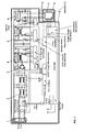
- Fig. 1 shows the modules of a primary part, as it finds application in a system for contactless energy transfer, for example.
- Such systems are used, for example, for contactless charging of the traction batteries of electric vehicles, where the energy for charging the battery through the primary coil of the primary part is transmitted to the secondary coil according to the principle of a transformer and converted there into a charging current for the battery.
- the primary part which must also provide for the regulation of the transmitted energy, typically and as in Fig. 1 recognizable a network connection 1, an input filter and a protection circuit, preferably realized by a common assembly 2, a rectifier 3, a power factor correction filter 4, possibly a boost converter, a DC / DC down converter 5, a resonant DC / AC converter 6, and at least a primary coil 7.
- a network connection typically and as in Fig. 1 recognizable a network connection 1, an input filter and a protection circuit, preferably realized by a common assembly 2, a rectifier 3, a power factor correction filter 4, possibly a boost converter, a DC / DC down converter 5, a resonant DC / AC converter 6, and at least a primary coil 7.
- Conventional systems distribute these modules on several, at least two, units 8, 9, which are connected to each other via energy and / or data lines. From the resonant DC / AC converter 6 to the primary coil 7 even expensive and sensitive high-frequency lines 10 must be provided.
- the unit combined in a first housing 8 usually comprises at least the mains connection 1 and the associated electronics 2, i. at least one input filter and the protection circuit, as well as fans.
- the unit 8 is usually designed for wall mounting.
- additional electronics are integrated with the first housing 8, such as the rectifier 3, power factor correction filter 4, if any, the boost converter, the DC / DC buck converter 5, and the DC / AC resonant converter 6.
- a power factor correction filter 4 is an electrical or electronic circuit which increases the so-called power factor so that it remains within a legal range.
- first housing 8 From the first housing 8 lead high-frequency lines 10 to a second housing 9, which comprises at least one primary coil 7.
- This second housing 9 is typically placed below an electric vehicle to be charged, lying on the floor of a garage or charging station, embedded in the ground below a parking space of the vehicle, od. Like.
- the DC / DC buck converter in Fig. 1 denoted by the reference numeral 5
- exposed expensive high-frequency lines in Fig. 1 marked with 10
- At least one heat-conducting element can dissipate the heat generated therein to the outside, for example to the ground or the surrounding air.
- Heat-conducting elements may preferably be copper or aluminum plates, which connect the housing 11 with at least one of the components arranged therein.
- these are preferably equipped with hollow channels in which a medium for heat transport, such as air or water circulates.
- a transformer element according to the invention can also be operated directly at any conventional power source as the primary part of a contactless charging system due to the high degree of integration. For this purpose, only a corresponding connection of the housing 11 arranged in the circuit arrangement is provided.
- the interior of the housing 11 may be filled with a potting compound which surrounds the components contained therein to substantially improve heat transfer and dielectric strength as well as mechanical strength and resistance to mechanical stresses.
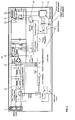
- each input of the resonant DC / AC converter 6 is followed by a respective controllable switching arrangement 12, each with a common control unit 13, optionally including a self-oscillating driver 14, is actuated.
- This combination of circuit arrangements 12 and the arrangement of control unit 13 and driver 14 allows influencing the excitation of the resonant DC / AC converter 6, which determines the transmitted power.
- a voltage control by, for example, a DC / DC down converter can thus be avoided, so that the resonant DC / AC converter 6 can be connected directly downstream of the boost converter 4 and can be supplied with DC voltage from it.
- control electronics comprising at least the control unit 13 and the self-oscillating driver 14, a sequence for driving the switching devices 12 is advantageously implemented according to which alternately one of the switching devices 12 is switched continuously and the other switching device 12 is switched off.
- the control unit 13 together with the driver 14 provides a sequence for driving the switching arrangements 12, in which for a switching cycle successively both switching arrangements 12 are switched continuously, preferably for equal shares of the cycle time.
- each of the two switching arrangement 12 is switched open or fired for substantially half the cycle time.
- the control of the switching elements of the switching assemblies 12 is such that they are switched on and off at the zero crossing of the current, which minimizes the losses. It may also happen that the switching frequency, which differs from the resonant frequency of the resonant converter 6, but this is quite desirable to make optimal use of the energy fed in despite simple control.
- an output of the converter 6 is permanently connected to an input of the converter 6 and only the other output is alternately connected to one or the other input of the converter 6.
- the cycle time can also be varied in integer steps depending on the power to be transmitted, in which case the resonant circuit oscillates with the harmonic of the switching frequency of the converter 6.
- the switching can be done with one third or one fifth of the resonant frequency of the transducer 6, and accordingly only one third or one fifth of the power is transmitted from the primary part to the secondary part.
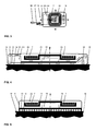
- the common housing 11 of the primary part is shaped in the form of a substantially cuboidal, preferably rectangular and thin in one dimension relative to the other dimensions thin plate.
- the housing 11 is thermally and preferably also mechanically connected to the floor 12, could also be embedded in the floor 12.
- the housing 11 is closed on all sides or at least closable and consists of a good heat-conducting, preferably metallic material such as aluminum. It is provided with an internally mounted and structured metal plate 13, in which cooling channels 14 are formed, in which a coolant, preferably air, in a closed circuit - symbolized by the arrows designated 15 - circulates. This circuit 15 is supported or driven by the fan 16.
- electronic assemblies 2 to 6 are arranged, for example, rectifier 3, boost converter, power factor correction filter 4, DC / DC down converter 5, inverter and resonant DC / AC converter 6, which draw their energy via a power cord 17 with power plug 18 directly from the AC power and their waste heat to the metal plate 13.
- This waste heat is absorbed by the cooling air in the circuit 15 and discharged at flow through the cooling channels 14 to the bottom 12 (symbolized by the arrows 19).
- the housing 11 has on its in use position the secondary part facing side, in the illustrated case of lying on the floor 12 or mounted plate above, an opening which is air-tight and waterproof covered by a non-metallic plate 20.
- a non-metallic plate 20 Under this plate 20 is the arrangement for contactless transmission of energy to the secondary part, consisting preferably of the primary coil 7 and preferably a ferrite screen 21 and a resonant capacitor 22, which is electrically and thermally isolated by an insulating plate 23 of the metallic plate 13 to In particular, to cope with the high resonance voltages occurring and to prevent a backflow of heat upwards.
- This arrangement with the resonant circuit is cooled by the exhaust air circulating in the housing 11 of the electronic assemblies.
Abstract
Ein Übertragerelement ist als Primärteil für ein System zur kontaktlosen Energieübertragung auf ein Sekundärteil vorgesehen. Es umfasst zumindest eine Primärspule (7) und eine Energieversorgung und Ansteuerelektronik (2 bis 15) für die Primärspule (7). Die Schaltungsanordnung für den Primärteil ist in einem gemeinsamen Gehäuse (11) untergebracht. Vorzugsweise ist auch jede Primärspule (7) im gemeinsamen Gehäuse (11) untergebracht.A transformer element is provided as a primary part for a system for contactless energy transfer to a secondary part. It comprises at least one primary coil (7) and a power supply and control electronics (2 to 15) for the primary coil (7). The circuit arrangement for the primary part is housed in a common housing (11). Preferably, each primary coil (7) is housed in the common housing (11).
Description
Die Erfindung betrifft eine Schaltungsanordnung für den Primärteil eines Systems zur kontaktlosen Energieübertragung, nach dem Oberbegriff des Anspruchs 1, sowie ein Übertragerelement als Primärteil für ein System zur kontaktlosen Energieübertragung auf einen Sekundärteil, nach dem Oberbegriff des Anspruchs 6.The invention relates to a circuit arrangement for the primary part of a system for contactless energy transmission, according to the preamble of claim 1, and a Übertragerelement as a primary part for a system for contactless energy transfer to a secondary part, according to the preamble of claim. 6
In der
Die Primärseite jedoch, die aus dem Stromnetz gespeist wird und die Energie für den Betrieb und/oder das Laden des Energiespeichers der Sekundärseite zur Verfügung stellt, ist typischerweise aufgrund vieler verschiedener Baugruppen als Anordnung mehrerer getrennter Einheiten aufgebaut. Die Primärseite muss neben dem Netzanschluss noch einen oder mehrere der Baugruppen Eingangsfilter, Schutzschaltung, Gleichrichter, Leistungsfaktorkorrekturfilter, Aufwärtswandler, dann typischerweise DC/DC-Abwärtswandler, resonanter DC/AC Wandler, Hochfrequenz-Leitungen sowie zumindest eine Primärspule aufweisen.However, the primary side, which is fed from the grid and provides the energy for the operation and / or charging of the energy store on the secondary side, is typically constructed as an arrangement of several separate units due to many different assemblies. In addition to the mains connection, the primary side must also have one or more of the modules input filter, protection circuit, rectifier, power factor correction filter, up-converter, then typically DC / DC down converter, resonant DC / AC converter, high-frequency lines and at least one primary coil.
Ein typischer Aufbau sieht eine Elektronik mit Lüftern für die Wandmontage vor, von welcher Hochfrequenz-Leitungen zu weiterer Elektronik am oder im Fussboden gehen, welche dann die Primärspule des unter dem Auto am oder im Fussboden, im Boden, in einer Fahrbahn od.dgl. speist.A typical design provides an electronics with fans for wall mounting, from which high frequency cables go to other electronics on or in the floor, which then the primary coil of the under the car or in the floor, in the ground, in a roadway or the like. fed.
Im Primärteil ist auch die Regelung der zu übertragenden Energie zu verwirklichen. Dazu umfasst der Primärteil typischerweise eine Spannungsregelungsvorrichtung.In the primary part, the regulation of the energy to be transmitted is to be realized. For this purpose, the primary part typically comprises a voltage regulation device.
Aufgabe der vorliegenden Erfindung ist es somit, eine möglichst hohe Integration auch für den Primärteil eines Systems zur kontaktlosen Energieübertragung zu erreichen und diesen Primärteil zu diesem Zweck schaltungstechnisch und baulich zu vereinfachen. Auch die Mitnahme im Fahrzeug zur Verbindung mit üblichen Stromquellen an jedem beliebigen Ort soll damit ermöglicht werden.Object of the present invention is thus to achieve the highest possible integration for the primary part of a system for contactless energy transfer and simplify this primary part for this purpose circuitry and construction. The entrainment in the vehicle for connection to conventional power sources at any location should be possible.
Die Aufgabe wird durch die Merkmale der unabhängigen Ansprüche 1 bzw. 6 gelöst. Vorteilhafte Weiterbildungen sind in den Figuren und in den jeweils abhängigen Patentansprüchen dargelegt.The object is solved by the features of
Typischerweise weist eine Schaltungsanordnung für den Primärteil eines Systems zur kontaktlosen Energieübertragung zumindest einen Netzanschluss, einen Gleichrichter, einen Aufwärtswandler, vorzugsweise mit Leistungsfaktorkorrekturfilter, einen resonanten DC/AC Wandler und Ausgänge zu zumindest einer Primärspule auf, gegebenenfalls auch ein Eingangsfilter und eine Schutzschaltung zwischen Netzanschluss und Gleichrichter.Typically, a circuit arrangement for the primary part of a system for contactless energy transmission at least a power supply, a rectifier, a step-up converter, preferably with power factor correction filter, a resonant DC / AC converter and outputs to at least one primary coil, optionally also an input filter and a protection circuit between power supply and rectifier.
Gemäss der Erfindung ist diese Anordnung zur Lösung der Aufgabe dadurch gekennzeichnet, dass jedem Eingang des resonanten DC/AC-Wandlers je eine ansteuerbare Schaltanordnung nachgeschaltet ist, wobei jeder Eingang des Wandlers bei durchgängig geschalteter Schaltanordnung mit einer Kapazität und einem ersten Ausgang des Wandlers verbunden ist, und wobei jeder Eingang des Wandlers bei gesperrt geschalteter Schaltanordnung mit einer Kapazität und einem zweiten Ausgang des Wandlers verbunden ist. Dieser neuartige Aufbau macht die Spannungsregelung durch beispielsweise einen DC/DC-Abwärtswandler unnötig, da die übertragene Leistung bei konstanter Spannung durch eine Veränderung der Anregung des resonanten Wandlers mittels der Schaltanordnungen geregelt werden kann.According to the invention, this arrangement for achieving the object is characterized in that each input of the resonant DC / AC converter is followed by a respective controllable switching arrangement, wherein each input of the converter is connected to continuously switched switching arrangement with a capacitor and a first output of the converter and wherein each input of the converter is connected to a switched capacitor switching arrangement with a capacitance and a second output of the converter. This novel structure eliminates the voltage regulation by, for example, a DC / DC buck converter, since the transmitted power at constant voltage can be regulated by changing the excitation of the resonant converter by means of the switching arrangements.
Vorteilhafterweise kann daher der resonante DC/AC-Wandler unmittelbar dem Aufwärtswandler nachgeschaltet sein und von diesem mit Gleichspannung versorgt werden. Durch diese Einsparung einer Baugruppe ist die Voraussetzung geschaffen, dass der Grossteil der elektrischen und elektronischen Bauteile zusammen mit der oder jeder Primärspule in einem gemeinsamen Gehäuse untergebracht werden kann. Damit können auch die teuren Hochfrequenz-Leitungen zwischen Elektronik und Primärspule vermieden werden, was mehr Flexibilität und einen grösseren Installationsradius ermöglicht und die elektromagnetische Verträglichkeit verbessert.Advantageously, therefore, the resonant DC / AC converter can be connected directly downstream of the boost converter and be supplied by this with DC voltage. By this saving of an assembly the condition is created that the majority of the electrical and electronic components can be accommodated together with the or each primary coil in a common housing. Thus, the expensive high-frequency lines between electronics and primary coil can be avoided, which allows more flexibility and a larger installation radius and improves the electromagnetic compatibility.
Gemäss einer vorteilhaften Ausführungsform der Erfindung sind die Schaltanordnungen mit einer Steuerungselektronik verbunden, in welcher ein Ablauf zur Ansteuerung der Schaltanordnungen implementiert ist, um abwechselnd je eine der Schaltanordnungen durchgängig zu schalten und die jeweils andere Schaltanordnung gesperrt zu schalten. Durch diese veränderbare Anregung des resonanten Wandlers des Primärteils kann trotz konstanter anliegender Spannung mittels einer vereinfachten und baulich kleineren Schaltung die übertragene Leistung stufenweise geregelt werden.According to an advantageous embodiment of the invention, the switching arrangements are connected to a control electronics, in which a sequence for driving the switching arrangements is implemented to switch alternately one of the switching arrangements continuously and to turn off the other switching arrangement blocked. As a result of this variable excitation of the resonant converter of the primary part, the transmitted power can be regulated step by step despite a constant applied voltage by means of a simplified and structurally smaller circuit.
Vorzugsweise ist dabei vorgesehen, dass in der Steuerungselektronik ein Ablauf zur Ansteuerung der Schaltanordnungen implementiert ist, der für einen Schaltzyklus nacheinander beide Schaltanordnungen durchgängig schaltet, vorzugsweise für gleiche Anteile an der Zykluszeit, insbesondere jede Schaltanordnung im Wesentlichen die halbe Zykluszeit. Vorzugsweise erfolgt die Ansteuerung der Schaltelemente so, dass sie im Nulldurchgang des Stromes ein- und ausgeschaltet werden, um die Verluste zu minimieren. Unter bestimmten Gegebenheiten ergibt sich dabei eine Umschaltfrequenz, die von der Resonanzfrequenz abweicht, was aber durchaus erwünscht ist. Diese Auslegung der Steuerungselektronik ergibt eine optimale Ausnutzung der eingespeisten Energie mit einfacher Regelungsmöglichkeit.Preferably, it is provided that in the control electronics, a sequence for driving the switching arrangements is implemented, the switching continuously switching circuit for a switching cycle, preferably for equal shares of the cycle time, in particular each switching arrangement substantially half the cycle time. Preferably, the control of the switching elements takes place in such a way that they are switched on and off in the zero crossing of the current in order to minimize the losses. Under certain circumstances, this results in a switching frequency, which deviates from the resonant frequency, but this is quite desirable. This design of the control electronics results in optimal utilization of the energy supplied with simple control option.
Eine Reduktion der Leistung auf die Hälfte lässt sich auf einfache Weise erreichen, indem durch entsprechende Ansteuerung der Schalteranordnungen ein Ausgang des Wandlers dauernd mit einem Eingang des Wandlers verbunden bleibt und nur der andere Ausgang wechselweise mit dem einen oder anderen Eingang des Wandlers verbunden wird.A reduction of the power to half can be achieved in a simple manner by an output of the converter permanently connected by an appropriate control of the switch arrangements with an input of the converter and only the other output alternately connected to one or the other input of the converter.
Eine vorteilhafte Weiterbildung sieht vor, dass in der Steuerungselektronik ein Ablauf zur Ansteuerung der Schaltanordnungen implementiert ist, der die Zykluszeit in Abhängigkeit von der zu übertragenden Leistung in ganzzahligen Schritten verändert, und zwar so, dass der Resonanzkreis mit der Oberwelle der Umschaltfrequenz des Wandlers schwingt. Beispielsweise kann die Umschaltung mit einem Drittel oder einem Fünftel der Resonanzfrequenz erfolgen, entsprechend wird nur ein Drittel oder ein Fünftel der Frequenz übertragen und so die Leistung auf einen Drittel oder einen Fünftel des ursprünglichen Wertes reduziert.An advantageous development provides that in the control electronics, a sequence for driving the switching arrangements is implemented, which varies the cycle time in response to the power to be transmitted in integer steps, in such a way that the resonant circuit oscillates with the harmonic of the switching frequency of the converter. For example, the switching can be done with one-third or one-fifth of the resonance frequency, corresponding to only one-third or one-fifth of the frequency is transmitted, thus reducing the power to one third or one fifth of the original value.
Zur Lösung der eingangs gestellten Aufgabe ist auch ein Übertragerelement als Primärteil für ein System zur kontaktlosen Energieübertragung auf ein Sekundärteil geeignet, welches eine Schaltungsanordnung nach zumindest einem der vorhergehenden Absätze umfasst, die in einem gemeinsamen Gehäuse untergebracht ist. Dies umfasst zumindest eine Energieversorgung sowie die Ansteuerelektronik für die Primärspule.To achieve the object set out, a transformer element is also suitable as a primary part for a system for contactless energy transmission to a secondary part, which comprises a circuit arrangement according to at least one of the preceding paragraphs, which is accommodated in a common housing. This includes at least one power supply and the control electronics for the primary coil.
Für eine noch grössere Integration und verbesserte Mitnahmemöglichkeit zur Verwendung des Primärteils an einem beliebigen Platz, der nur über eine Stromquelle verfügen muss, ist zusätzlich jede Primärspule im gemeinsamen Gehäuse untergebracht.In addition, each primary coil is housed in the common housing for even greater integration and enhanced portability to use the primary in any location that needs only one power source.
Wenn bei einer vorteilhaften Ausführungsform des Übertragerelementes zumindest ein wärmeleitendes Element, vorzugsweise Kupfer- oder Aluminiumplatten, das Gehäuse mit zumindest einem der darin angeordneten Bauteile verbindet, kann durch Kontakt des Gehäuses mit einer kühlen Fläche eine für den Ladezyklus ausreichende Kühlung des Primärteils gewährleistet werden. Die kühle Fläche kann beispielsweise der Boden unterhalb eines zu ladenden Elektrofahrzeuges sein. Um die Lokal anfallende Wärme der elektrischen und elektronischen Bauteile im Übertragerelement über die gesamte Fläche der Platten zu verteilen und so optimal an den Boden abzugeben, können die Platten mit Hohlkanälen ausgestattet sein, in denen ein Medium zum Wärmetransport zirkuliert, vorzugsweise Luft oder Wasser.If, in an advantageous embodiment of the transformer element, at least one heat-conducting element, preferably copper or aluminum plates, connects the housing to at least one of the components arranged therein, cooling of the primary part sufficient for the charging cycle can be ensured by contact of the housing with a cool surface. The cool surface may be, for example, the ground below an electric vehicle to be charged. To distribute the local accumulating heat of the electrical and electronic components in the transformer element over the entire surface of the plates and so To deliver optimally to the ground, the plates may be equipped with hollow channels in which a medium circulates for heat transport, preferably air or water.
Ein vorteilhaftes Übertragerelement ist dadurch gekennzeichnet, dass die im Gehäuse angeordnet Schaltungsanordnung mit einem Anschluss für eine herkömmliche Stromversorgung versehen ist. Damit kann in einfacher Weise der Primärteil an jeder beliebigen herkömmlichen Stromquelle betrieben werden, was die höchstmögliche Flexibilität für den Betrieb des Primärteils bietet.An advantageous transmitter element is characterized in that the circuit arrangement arranged in the housing is provided with a connection for a conventional power supply. Thus, in a simple manner, the primary part can be operated on any conventional power source, which offers the highest possible flexibility for the operation of the primary part.
Als weitere alternative Ausführungsform kann ein Übertragerelement dadurch gekennzeichnet sein, dass der Innenraum des Gehäuses eine Vergussmasse aufweist, welche die darin enthaltenen Bauteile umgibt. Damit kann einerseits die Wärmeübertragung und die Spannungsfestigkeit erhöht werden, anderseits kann auch die mechanische Festigkeit und die Widerstandfähigkeit gegenüber mechanischen Beanspruchungen wesentlich verbessert werden.As a further alternative embodiment, a transmitter element may be characterized in that the interior of the housing has a potting compound which surrounds the components contained therein. Thus, on the one hand, the heat transfer and the dielectric strength can be increased, on the other hand, the mechanical strength and the resistance to mechanical stresses can be significantly improved.
Weitere Vorteile, Merkmale und Einzelheiten der Erfindung ergeben sich aus der nachfolgenden Beschreibung, in der unter Bezugnahme auf die Zeichnungen Ausführungsbeispiele der Erfindung beschrieben sind. Dabei können die in den Ansprüchen und in der Beschreibung erwähnten Merkmale jeweils einzeln für sich oder in beliebiger Kombination erfindungswesentlich sein.Further advantages, features and details of the invention will become apparent from the following description in which embodiments of the invention are described with reference to the drawings. The features mentioned in the claims and in the description may each be essential to the invention individually or in any desired combination.
Die Bezugszeichenliste ist Bestandteil der Offenbarung. Die Figuren werden zusammenhängend und übergreifend beschrieben. Gleiche Bezugszeichen bedeuten gleiche Bauteile, Bezugszeichen mit unterschiedlichen Indices geben funktionsgleiche oder ähnliche Bauteile an.The list of reference numerals is part of the disclosure. The figures are described coherently and comprehensively. The same reference symbols denote the same components, reference symbols with different indices indicate functionally identical or similar components.
Es zeigen dabei:
- Fig. 1
- ein elektrisches Schaltbild eines herkömmlichen Primärteils gemäss dem Stand der Technik,
- Fig. 2
- ein elektrisches Schaltbild eines erfindungsgemässen Primärteils,
- Fig. 3
- eine schematische Draufsicht auf eine Ausführungsform eines erfindungsgemässen Primärteils,
- Fig. 4
- einen Schnitt entlang der Linie A-A der
Fig. 3 , und - Fig. 5
- einen Schnitt entlang der Linie B-B der
Fig. 3 .
- Fig. 1
- an electrical circuit diagram of a conventional primary part according to the prior art,
- Fig. 2
- an electrical circuit diagram of a primary part according to the invention,
- Fig. 3
- a schematic plan view of an embodiment of a primary part according to the invention,
- Fig. 4
- a section along the line AA the
Fig. 3 , and - Fig. 5
- a section along the line BB of
Fig. 3 ,
Der Primärteil, der auch für die Regelung der übertragenen Energie sorgen muss, umfasst typischerweise und wie in
Die in einem ersten Gehäuse 8 zusammengefasste Einheit umfasst üblicherweise zumindest den Netzanschluss 1 und die zugehörige Elektronik 2, d.h. zumindest ein Eingangsfilter und die Schutzschaltung, sowie Lüfter. Die Einheit 8 ist meist für die Wandmontage ausgelegt.The unit combined in a
Oftmals ist weitere Elektronik in das erste Gehäuse 8 integriert, wie etwa der Gleichrichter 3, ein Leistungsfaktorkorrekturfilter 4, wenn vorhanden der Aufwärtswandler, der DC/DC-Abwärtswandler 5 sowie der resonante DC/AC-Wandler 6.Often, additional electronics are integrated with the
Ein Leistungsfaktorkorrekturfilter 4 ist eine elektrische oder elektronische Schaltung, welche den sogenannten Leistungsfaktor erhöht, damit dieser in einem gesetzlich vorgegebenen Bereich bleibt.A power
Vom ersten Gehäuse 8 führen Hochfrequenz-Leitungen 10 zu einem zweiten Gehäuse 9, welche zumindest eine Primärspule 7 umfasst. Dieses zweite Gehäuse 9 ist typischerweise unterhalb eines zu ladenden Elektrofahrzeuges platziert, auf dem Fussboden einer Garage oder Ladestation liegend, im Boden unterhalb eines Abstellplatzes des Fahrzeuges eingelassen, od. dgl.From the
Durch die erfindungsgemässe Ausbildung der Schaltungsanordnung wie beispielsweise bei dem in
So ist beim dargestellten Ausführungsbeispiel der
Im Gehäuse 11 des Übertragerelementes des Primärteils kann zumindest ein wärmeleitendes Element die darin erzeugte Wärme nach aussen hin ableiten, beispielsweise an den Boden oder die umgebende Luft. Wärmeleitende Elemente können vorzugsweise Kupfer- oder Aluminiumplatten sein, die das Gehäuse 11 mit zumindest einem der darin angeordneten Bauteile verbinden. Um die lokal anfallende Wärme der elektronischen Bauteile über die gesamte Fläche der wärmeleitenden Elemente zu verteilen, sind diese vorzugsweise mit Hohlkanälen ausgestattet, in denen ein Medium zum Wärmetransport, wie etwa Luft oder Wasser, zirkuliert.In the
Ein erfindungsgemässes Übertragerelement kann als Primärteil eines kontaktlosen Ladesystems durch den hohen Grad der Integration auch unmittelbar an jeder beliebigen herkömmlichen Stromquelle betrieben werden. Dazu ist lediglich ein entsprechender Anschluss der im Gehäuse 11 angeordneten Schaltungsanordnung vorzusehen.A transformer element according to the invention can also be operated directly at any conventional power source as the primary part of a contactless charging system due to the high degree of integration. For this purpose, only a corresponding connection of the
Der Innenraum des Gehäuses 11 kann mit einer Vergussmasse verfüllt sein, welche die darin enthaltenen Bauteile umgibt, um Wärmeübertragung und die Spannungsfestigkeit als auch mechanische Festigkeit und die Widerstandfähigkeit gegenüber mechanischen Beanspruchungen wesentlich zu verbessern.The interior of the
Um trotz der Vereinfachung der Schaltung eine zumindest stufenweise Einstellung der vom Primärteil als magnetisches Wechselfeld abgegebenen Energie zu ermöglichen, ist jedem Eingang des resonanten DC/AC-Wandlers 6 je eine ansteuerbare Schaltanordnung 12 nachgeschaltet, die jede über eine gemeinsame Steuerungseinheit 13, gegebenenfalls unter Einbeziehung eines selbstoszillierenden Treibers 14, betätigbar ist. Dabei ist jeder Eingang des Wandlers 6 bei durchgängig geschalteter Schaltanordnung 12 mit einer Kapazität 15 und einem ersten Ausgang des Wandlers verbunden, und ist jeder Eingang des Wandlers bei gesperrt geschalteter Schaltanordnung 12 mit einer Kapazität 15 und einem zweiten Ausgang des Wandlers 6 verbunden.In order to enable an at least stepwise adjustment of the energy delivered by the primary part as a magnetic alternating field despite the simplification of the circuit, each input of the resonant DC /
Diese Kombination von Schaltungsanordnungen 12 und der Anordnung aus Steuerungseinheit 13 und Treiber 14 erlaubt eine Beeinflussung der Anregung des resonanten DC/AC-Wandlers 6, welche die übertragene Leistung bestimmt. Eine Spannungsregelung durch beispielsweise einen DC/DC-Abwärtswandler kann damit vermieden werden, so dass der resonante DC/AC-Wandler 6 unmittelbar dem Aufwärtswandler 4 nachgeschaltet sein und von diesem mit Gleichspannung versorgt werden kann.This combination of
In der Steuerungselektronik, umfassend zumindest die Steuerungseinheit 13 und den selbstoszillierenden Treiber 14, ist vorteilhafterweise ein Ablauf zur Ansteuerung der Schaltanordnungen 12 implementiert, gemäss dem abwechselnd je eine der Schaltanordnungen 12 durchgängig geschaltet und die jeweils andere Schaltanordnung 12 gesperrt geschaltet ist.In the control electronics, comprising at least the
Die Steuerungseinheit 13 zusammen mit dem Treiber 14 sorgt für einen Ablauf zur Ansteuerung der Schaltanordnungen 12, bei welchem für einen Schaltzyklus nacheinander beide Schaltanordnungen 12 durchgängig geschaltet werden, vorzugsweise für gleiche Anteile an der Zykluszeit. Insbesondere wird dabei jede der beiden Schaltanordnung 12 für im Wesentlichen die halbe Zykluszeit offen bzw. geschossen geschaltet.The
Vorzugsweise erfolgt die Ansteuerung der Schaltelemente der Schaltanordnungen 12 derart, dass sie im Nulldurchgang des Stromes ein- und ausgeschaltet werden, was die Verluste minimiert. Dabei kann es auch vorkommen, dass die Umschaltfrequenz, die von der Resonanzfrequenz des resonanten Wandlers 6 abweicht, was aber durchaus erwünscht ist, um trotz einfacher Regelung die eingespeiste Energie optimal auszunützen.Preferably, the control of the switching elements of the
So kann beispielsweise eine Reduktion der Leistung auf die erreichen, indem durch entsprechende Ansteuerung der Schaltanordnungen 12 ein Ausgang des Wandlers 6 dauernd mit einem Eingang des Wandlers 6 verbunden bleibt und nur der andere Ausgang wechselweise mit dem einen oder anderen Eingang des Wandlers 6 verbunden wird.Thus, for example, a reduction of the power to achieve that by an appropriate control of the switching
Die Zykluszeit kann auch in Abhängigkeit von der zu übertragenden Leistung in ganzzahligen Schritten verändert werden, wobei dann der Resonanzkreis mit der Oberwelle der Umschaltfrequenz des Wandlers 6 schwingt. So kann die Umschaltung mit einem Drittel oder einem Fünftel der Resonanzfrequenz des Wandlers 6 erfolgen, und entsprechend wird nur ein Drittel oder ein Fünftel der Leistung vom Primärteil auf den Sekundärteil übertragen.The cycle time can also be varied in integer steps depending on the power to be transmitted, in which case the resonant circuit oscillates with the harmonic of the switching frequency of the
In Bezug auf die
Das gemeinsame Gehäuse 11 des Primärteils ist in Form einer im Wesentlichen quaderförmigen, vorzugsweise rechteckigen und in einer Dimension gegenüber den anderen Abmessungen dünnen Platte geformt. Das Gehäuse 11 ist mit dem Fussboden 12 thermisch und vorzugsweise auch mechanisch verbunden, könnte auch in den Fussboden 12 eingelassen sein.The
Das Gehäuse 11 ist allseitig geschlossen oder zumindest verschliessbar und besteht aus einem gut wärmeleitenden, vorzugsweise metallischen Material wie etwa Aluminium. Es ist mit einer im Innern angebrachten und strukturierten Metallplatte 13 versehen, in welcher Kühlkanäle 14 ausgebildet sind, in welchen ein Kühlmittel, vorzugsweise Luft, in einem geschlossenen Kreislauf - symbolisiert durch die mit 15 bezeichneten Pfeile - zirkuliert. Dieser Kreislauf 15 wird durch den Ventilator 16 unterstützt oder angetrieben.The
Auf der Metallplatte 13 sind elektronische Baugruppen 2 bis 6 angeordnet, beispielsweise Gleichrichter 3, Hochsetzsteller, Leistungsfaktorkorrekturfilter 4, DC/DC-Abwärtswandler 5, Wechselrichter und resonanter DC/AC-Wandler 6, die ihre Energie über ein Netzkabel 17 mit Netzstecker 18 direkt vom Wechselstromnetz beziehen und ihre Abwärme an die Metallplatte 13 abgeben. Diese Abwärme wird von der Kühlluft im Kreislauf 15 aufgenommen und bei Durchströmung der Kühlkanäle 14 an den Boden 12 abgegeben (symbolisiert durch die Pfeile 19).On the
Das Gehäuse 11 hat an seiner in Gebrauchsstellung dem Sekundärteil zugewandten Seite, im dargestellten Fall eines auf dem Fussboden 12 liegenden oder daran montierten Platte oben, eine Öffnung, welche durch eine nichtmetallische Platte 20 luft- und wasserdicht abgedeckt ist. Unter dieser Platte 20 befindet sich die Anordnung zur kontaktlosen Übertragung der Energie auf den Sekundärteil, bestehend vorzugsweise aus der Primärspule 7 und vorzugsweise einem Ferritschirm 21 und einem Resonanzkondensator 22, welcher elektrisch und thermisch durch eine Isolierplatte 23 von der metallischen Platte 13 isoliert ist, um insbesondere den hohen auftretenden Resonanzspannungen gerecht zu werden und einen Rückfluss der Wärme nach oben zu verhindern. Diese Anordnung mit dem Resonanzkreis wird durch die im Gehäuse 11 zirkulierende Abluft der elektronischen Baugruppen gekühlt.The
- 11
- Netzanschlussmains connection
- 22
- Eingangsfilter und SchutzschaltungInput filter and protection circuit
- 33
- Gleichrichterrectifier
- 44
- LeistungsfaktorkorrekturfilterPower factor correction
- 55
- DC/DC-AbwärtswandlerDC / DC buck converter
- 66
- Resonanter DC/AC-WandlerResonant DC / AC converter
- 77
- Primärspuleprimary coil
- 88th
- Erstes GehäuseFirst case
- 99
- Zweites GehäuseSecond housing
- 1010
- Hochfrequenz-LeitungenHigh-frequency lines
- 1111
- Gemeinsames Gehäuse des PrimärteilsCommon housing of the primary part
- 1212
- Schaltanordnungswitching arrangement
- 1313
- Steuerungseinheitcontrol unit
- 1414
- Selbstoszillierender TreiberSelf-oscillating driver
- 1515
- Kapazitätcapacity
Claims (13)
dadurch gekennzeichnet, dass die im Gehäuse (11) angeordnete Schaltungsanordnung (2 bis 15) mit einem Anschluss (1) für eine herkömmliche Stromversorgung versehen ist.Ubertragerelement according to at least one of claims 8 to 11,
characterized in that the housing (11) arranged in the circuit arrangement (2 to 15) is provided with a connection (1) for a conventional power supply.
dadurch gekennzeichnet, dass der Innenraum des Gehäuses (11) eine Vergussmasse aufweist, welche die darin enthaltenen Bauteile (1 bis 15) umgibt.Transformer element according to at least one of claims 8 to 12,
characterized in that the interior of the housing (11) has a potting compound which surrounds the components (1 to 15) contained therein.
Priority Applications (3)
| Application Number | Priority Date | Filing Date | Title |
|---|---|---|---|
| EP13169729.4A EP2808976A1 (en) | 2013-05-29 | 2013-05-29 | Circuit assembly for the primary part of a system for contactless energy transfer, and transformer element |
| PCT/IB2014/061652 WO2014199255A1 (en) | 2013-05-29 | 2014-05-23 | Circuit arrangement for the primary part of a system for contactless energy transfer, and transfer element |
| EP14728347.7A EP3005526B1 (en) | 2013-05-29 | 2014-05-23 | Circuit assembly for the primary part of a system for contactless energy transfer, and transformer element |
Applications Claiming Priority (1)
| Application Number | Priority Date | Filing Date | Title |
|---|---|---|---|
| EP13169729.4A EP2808976A1 (en) | 2013-05-29 | 2013-05-29 | Circuit assembly for the primary part of a system for contactless energy transfer, and transformer element |
Publications (1)
| Publication Number | Publication Date |
|---|---|
| EP2808976A1 true EP2808976A1 (en) | 2014-12-03 |
Family
ID=48520786
Family Applications (2)
| Application Number | Title | Priority Date | Filing Date |
|---|---|---|---|
| EP13169729.4A Withdrawn EP2808976A1 (en) | 2013-05-29 | 2013-05-29 | Circuit assembly for the primary part of a system for contactless energy transfer, and transformer element |
| EP14728347.7A Active EP3005526B1 (en) | 2013-05-29 | 2014-05-23 | Circuit assembly for the primary part of a system for contactless energy transfer, and transformer element |
Family Applications After (1)
| Application Number | Title | Priority Date | Filing Date |
|---|---|---|---|
| EP14728347.7A Active EP3005526B1 (en) | 2013-05-29 | 2014-05-23 | Circuit assembly for the primary part of a system for contactless energy transfer, and transformer element |
Country Status (2)
| Country | Link |
|---|---|
| EP (2) | EP2808976A1 (en) |
| WO (1) | WO2014199255A1 (en) |
Cited By (4)
| Publication number | Priority date | Publication date | Assignee | Title |
|---|---|---|---|---|
| WO2019170838A1 (en) * | 2018-03-08 | 2019-09-12 | Mahle International Gmbh | Induction charging device |
| WO2021175887A1 (en) * | 2020-03-05 | 2021-09-10 | Mahle International Gmbh | Stationary induction charging device for wireless energy transfer |
| DE102020212388A1 (en) | 2020-09-30 | 2022-03-31 | Mahle International Gmbh | Bottom assembly for an inductive charging device |
| DE102020215074A1 (en) | 2020-11-30 | 2022-06-02 | Mahle International Gmbh | Electromagnetic induction charging device |
Families Citing this family (1)
| Publication number | Priority date | Publication date | Assignee | Title |
|---|---|---|---|---|
| DE102017207266A1 (en) | 2017-04-28 | 2018-10-31 | Mahle International Gmbh | Induction charging device |
Citations (4)
| Publication number | Priority date | Publication date | Assignee | Title |
|---|---|---|---|---|
| US6160374A (en) * | 1999-08-02 | 2000-12-12 | General Motors Corporation | Power-factor-corrected single-stage inductive charger |
| US20110254377A1 (en) * | 2010-04-08 | 2011-10-20 | Qualcomm Incorporated | Wireless power transmission in electric vehicles |
| WO2011151038A1 (en) * | 2010-06-02 | 2011-12-08 | Friwo Gerätebau Gmbh | Circuit for a system for contactless, inductive power transmission |
| WO2013017200A2 (en) | 2011-08-02 | 2013-02-07 | Sew-Eurodrive Gmbh & Co. Kg | Electronic device, in particular transmitter head, and system for wireless energy transfer |
Family Cites Families (1)
| Publication number | Priority date | Publication date | Assignee | Title |
|---|---|---|---|---|
| FR2750267B1 (en) | 1996-06-19 | 1998-09-18 | Peugeot | DEVICE FOR RECHARGING BATTERIES FROM AN ELECTRIC VEHICLE |
-
2013
- 2013-05-29 EP EP13169729.4A patent/EP2808976A1/en not_active Withdrawn
-
2014
- 2014-05-23 WO PCT/IB2014/061652 patent/WO2014199255A1/en active Application Filing
- 2014-05-23 EP EP14728347.7A patent/EP3005526B1/en active Active
Patent Citations (4)
| Publication number | Priority date | Publication date | Assignee | Title |
|---|---|---|---|---|
| US6160374A (en) * | 1999-08-02 | 2000-12-12 | General Motors Corporation | Power-factor-corrected single-stage inductive charger |
| US20110254377A1 (en) * | 2010-04-08 | 2011-10-20 | Qualcomm Incorporated | Wireless power transmission in electric vehicles |
| WO2011151038A1 (en) * | 2010-06-02 | 2011-12-08 | Friwo Gerätebau Gmbh | Circuit for a system for contactless, inductive power transmission |
| WO2013017200A2 (en) | 2011-08-02 | 2013-02-07 | Sew-Eurodrive Gmbh & Co. Kg | Electronic device, in particular transmitter head, and system for wireless energy transfer |
Non-Patent Citations (1)
| Title |
|---|
| CHING-MING LAI: "Study and implementation of a high power factor single-stage contactless power supply with load/gap detection mechanisms", POWER ELECTRONICS SYSTEMS AND APPLICATIONS (PESA), 2011 4TH INTERNATIONAL CONFERENCE ON, IEEE, 8 June 2011 (2011-06-08), pages 1 - 5, XP031925350, ISBN: 978-1-4577-0205-1, DOI: 10.1109/PESA.2011.5982896 * |
Cited By (8)
| Publication number | Priority date | Publication date | Assignee | Title |
|---|---|---|---|---|
| WO2019170838A1 (en) * | 2018-03-08 | 2019-09-12 | Mahle International Gmbh | Induction charging device |
| US11552502B2 (en) | 2018-03-08 | 2023-01-10 | Mahle International Gmbh | Induction charging device |
| WO2021175887A1 (en) * | 2020-03-05 | 2021-09-10 | Mahle International Gmbh | Stationary induction charging device for wireless energy transfer |
| CN115427254A (en) * | 2020-03-05 | 2022-12-02 | 马勒国际有限公司 | Stationary inductive charging device for wireless energy transmission |
| CN115427254B (en) * | 2020-03-05 | 2023-07-28 | 马勒国际有限公司 | Fixed induction charging device for wireless energy transmission |
| US11820245B2 (en) | 2020-03-05 | 2023-11-21 | Mahle International Gmbh | Stationary induction charging device for wireless energy transfer |
| DE102020212388A1 (en) | 2020-09-30 | 2022-03-31 | Mahle International Gmbh | Bottom assembly for an inductive charging device |
| DE102020215074A1 (en) | 2020-11-30 | 2022-06-02 | Mahle International Gmbh | Electromagnetic induction charging device |
Also Published As
| Publication number | Publication date |
|---|---|
| EP3005526B1 (en) | 2017-12-13 |
| EP3005526A1 (en) | 2016-04-13 |
| WO2014199255A1 (en) | 2014-12-18 |
Similar Documents
| Publication | Publication Date | Title |
|---|---|---|
| DE112015001844T5 (en) | Charger for electric vehicles | |
| WO2016037737A1 (en) | Transmission coil for inductive energy transfer | |
| EP3005526B1 (en) | Circuit assembly for the primary part of a system for contactless energy transfer, and transformer element | |
| EP3428000A1 (en) | Device for charging at least one battery | |
| EP3524463B1 (en) | Electronic unit for inductive charging systems | |
| EP2885853B1 (en) | Switchable energy storage device and method for operating a switchable energy storage device | |
| DE112016003577T5 (en) | Charger with integrated DC / DC converter | |
| DE102009028973A1 (en) | DC / DC converter circuit and battery system | |
| DE102013217816A1 (en) | Device for inductive energy transmission and method for operating a device for inductive energy transmission | |
| DE102009052680A1 (en) | Charging device for high voltage battery of e.g. electric vehicle, has step down converter arranged upstream of step up converter for lowering input direct voltage such that step down converter provides charging voltage for battery | |
| DE4330618A1 (en) | Cooling device for a battery charger and an on-board electrical system converter in electric vehicles | |
| DE112006002319T5 (en) | High performance, high current snap-in connector with integrated EMI filtering | |
| DE102019204141A1 (en) | VEHICLE INTERNAL MOTOR-DRIVEN COMPRESSOR | |
| DE202019101527U1 (en) | Static Converter | |
| EP3065152A1 (en) | Primary section of an inductive charger | |
| EP3536535B1 (en) | Charger for a motor vehicle | |
| DE102014220224A1 (en) | Method and system for the contactless charging of a battery-operated object | |
| WO2015144619A1 (en) | Magnetic circuit for dynamically charging electric vehicles | |
| DE112019003942T5 (en) | Wired / wireless integrated power receiving system | |
| DE102013109223A1 (en) | Switching power supply apparatus | |
| DE102008009913A1 (en) | Electronic power converter module for power electronics, has semiconductor module, which is arranged on base body, and has two direct current connections | |
| DE102014201440A1 (en) | Motor vehicle electrical system with optimized switching function | |
| DE102017106726A1 (en) | Power transmission device | |
| DE102011089989A1 (en) | Arrangement for charging battery of car, in garage, has reception unit connected with inputs of charging unit over output of reception unit, where one of inputs of charging unit is connected with intermediate circuit capacitor | |
| WO2010009971A1 (en) | Multiphase switched dc/dc converter |
Legal Events
| Date | Code | Title | Description |
|---|---|---|---|
| PUAI | Public reference made under article 153(3) epc to a published international application that has entered the european phase |
Free format text: ORIGINAL CODE: 0009012 |
|
| 17P | Request for examination filed |
Effective date: 20130529 |
|
| AK | Designated contracting states |
Kind code of ref document: A1 Designated state(s): AL AT BE BG CH CY CZ DE DK EE ES FI FR GB GR HR HU IE IS IT LI LT LU LV MC MK MT NL NO PL PT RO RS SE SI SK SM TR |
|
| AX | Request for extension of the european patent |
Extension state: BA ME |
|
| STAA | Information on the status of an ep patent application or granted ep patent |
Free format text: STATUS: THE APPLICATION IS DEEMED TO BE WITHDRAWN |
|
| 18D | Application deemed to be withdrawn |
Effective date: 20150604 |