EP2889146A2 - Recording apparatus - Google Patents
Recording apparatus Download PDFInfo
- Publication number
- EP2889146A2 EP2889146A2 EP14199831.0A EP14199831A EP2889146A2 EP 2889146 A2 EP2889146 A2 EP 2889146A2 EP 14199831 A EP14199831 A EP 14199831A EP 2889146 A2 EP2889146 A2 EP 2889146A2
- Authority
- EP
- European Patent Office
- Prior art keywords
- roller
- carriage
- transport
- recording apparatus
- medium
- Prior art date
- Legal status (The legal status is an assumption and is not a legal conclusion. Google has not performed a legal analysis and makes no representation as to the accuracy of the status listed.)
- Granted
Links
Images







Classifications
-
- B—PERFORMING OPERATIONS; TRANSPORTING
- B41—PRINTING; LINING MACHINES; TYPEWRITERS; STAMPS
- B41J—TYPEWRITERS; SELECTIVE PRINTING MECHANISMS, i.e. MECHANISMS PRINTING OTHERWISE THAN FROM A FORME; CORRECTION OF TYPOGRAPHICAL ERRORS
- B41J25/00—Actions or mechanisms not otherwise provided for
- B41J25/34—Bodily-changeable print heads or carriages
-
- B—PERFORMING OPERATIONS; TRANSPORTING
- B41—PRINTING; LINING MACHINES; TYPEWRITERS; STAMPS
- B41J—TYPEWRITERS; SELECTIVE PRINTING MECHANISMS, i.e. MECHANISMS PRINTING OTHERWISE THAN FROM A FORME; CORRECTION OF TYPOGRAPHICAL ERRORS
- B41J29/00—Details of, or accessories for, typewriters or selective printing mechanisms not otherwise provided for
- B41J29/38—Drives, motors, controls or automatic cut-off devices for the entire printing mechanism
-
- B—PERFORMING OPERATIONS; TRANSPORTING
- B41—PRINTING; LINING MACHINES; TYPEWRITERS; STAMPS
- B41J—TYPEWRITERS; SELECTIVE PRINTING MECHANISMS, i.e. MECHANISMS PRINTING OTHERWISE THAN FROM A FORME; CORRECTION OF TYPOGRAPHICAL ERRORS
- B41J11/00—Devices or arrangements of selective printing mechanisms, e.g. ink-jet printers or thermal printers, for supporting or handling copy material in sheet or web form
-
- B—PERFORMING OPERATIONS; TRANSPORTING
- B41—PRINTING; LINING MACHINES; TYPEWRITERS; STAMPS
- B41J—TYPEWRITERS; SELECTIVE PRINTING MECHANISMS, i.e. MECHANISMS PRINTING OTHERWISE THAN FROM A FORME; CORRECTION OF TYPOGRAPHICAL ERRORS
- B41J11/00—Devices or arrangements of selective printing mechanisms, e.g. ink-jet printers or thermal printers, for supporting or handling copy material in sheet or web form
- B41J11/36—Blanking or long feeds; Feeding to a particular line, e.g. by rotation of platen or feed roller
-
- B—PERFORMING OPERATIONS; TRANSPORTING
- B65—CONVEYING; PACKING; STORING; HANDLING THIN OR FILAMENTARY MATERIAL
- B65H—HANDLING THIN OR FILAMENTARY MATERIAL, e.g. SHEETS, WEBS, CABLES
- B65H1/00—Supports or magazines for piles from which articles are to be separated
Definitions
- the present invention relates to a recording apparatus represented by facsimile machines, printers, and the like.
- a pair of transport rollers for transporting a recording sheet, as an example of a medium is provided on the upstream side of the recording head.
- the transport roller pair is usually configured from a drive roller that is driven by a motor and a driven roller that presses toward the drive roller (e.g., Japanese Laid-Open Patent Publication No. 2006-247932 ).
- the drive roller is produced by forming a high friction layer on the outer peripheral surface of a solid metal shaft or a hollow metal shaft.
- the driven roller is formed by resin molding.
- the recording paper is transported to the downstream side by the rotational drive of the drive roller in the state in which the paper is pinched by the drive roller and the driven roller.
- the width dimension of the printer is examined, the width dimension is determined for the most part by the width of the movement region of the carriage, and the sizes and the placement positions of structural elements that are arranged on the outside of the movement region. Because the movement region of the carriage is determined by the paper width and cannot be reduced, a reduction of the space occupied by structural elements that are arranged outside of the carriage movement region is essential in reducing the width dimension.
- Japanese Laid-Open Patent Publication No. 2006-289770 discloses a configuration in which an encoder scale is arranged outside of the carriage movement region as an example.
- Japanese Laid-Open Patent Publication No. 2006-247932 discloses a technology that forms in advance a gap smaller than the thickness of the recording paper between the drive roller and the driven roller. According to this, the kicking phenomenon can be suppressed even if the thickness of the recording paper is increased.
- the present invention solves at least a portion of the problems described above and can be implemented in the following modes or embodiments.
- a recording apparatus related to a first embodiment of the invention is provided with a carriage including a recording head configured to record on the medium and move in a first direction and a second direction that is an opposite direction thereto, a support unit supporting the carriage, and a power transmission mechanism configured to transmit power of a drive source to a transport unit configured to transport the medium. At least a part of the power transmission mechanism is positioned below the carriage that is moved to an end part in the second direction.
- the power transmission mechanism is incorporated into the region required for the movement of the carriage because at least a part of the power transmission mechanism is positioned below the carriage when moved to the end part in the second direction.
- the width dimension of the apparatus can be limited, and the carriage volume can be ensured.
- a second embodiment is the first embodiment in which the carriage is provided with a projection unit that projects in the second direction, forms an asymmetric form in a movement direction with respect to the center of a target support region that is supported by the support unit in the movement direction, and at least a part of the power transmission mechanism is positioned below the projecting part of the carriage when moved to the end part in the second direction.
- a third embodiment is the first embodiment in which the carriage is provided with an ink cartridge configured to store ink, the ink cartridge is detachably arranged to the carriage, and the ink cartridge is arranged to occupy a space that includes the projecting part in the carriage.
- the ink cartridge storing the ink occupies space that includes the projecting part in the carriage; therefore, the volume of ink in the ink cartridge can be ensured.
- a fourth embodiment is any of the first to the third embodiments in which the transport unit is provided with a first roller provided on an upstream side of the recording head and a second roller provided on the downstream side of the recording head in the transport path of the medium, the power transmission mechanism includes a first roller drive gear provided in a shaft end unit of the first roller and is configured to transmit power to the second roller through the first roller drive gear, and a rotary scale that constitutes a rotation detection unit configured to detect a rotation of the first roller is provided on a side of the first direction with respect to the first roller drive gear.
- the rotary scale is provided on the first direction side with respect to the first roller drive gear, the placement of a detection unit that reads the rotary scale on the outermost side (outside in the carriage movement direction) of the apparatus body can be avoided; and an increase in the dimensions of the apparatus body (dimension in the carriage movement direction) can be limited.
- a fifth embodiment is the fourth embodiment in which a diameter of the rotary scale is smaller than a diameter of the first roller drive gear.
- the convex part formed in the frame forms an arc shape that is along the exterior shape of the rotary scale and has a diameter larger than the diameter of the rotary scale
- the convex part has the function of a shielding wall for the rotary scale and prevents ink mist from adhering to the rotary scale.
- a seventh embodiment is the sixth embodiment in which the carriage has a concave part that avoids the convex part when the carriage moved to the end part in the second direction.
- an increase in the width dimension of the apparatus can be limited without the need to set the position of the frame on the outside in order to ensure the movement region of the carriage (in order to prevent interference of the carriage and the frame).
- the diameter of the driven roller is larger than the diameter of the drive roller and obtains the following actions and effects. That is, the back end of the medium is pressed between the driven roller and the drive roller. Then for the pushing force accompanying the pressing force of the driven roller, the pushing force by the drive roller that has a relatively small diameter becomes larger than the pushing force by the driven roller that has a relatively large diameter.
- the rotation of the driven roller acts to forcefully push out the back end of the medium because the driven roller is capable of free rotation.
- the drive roller because the drive roller is connected to the drive source and is unable to rotate freely, the drive roller does not act to forcefully push out the back end of the medium compared with the driven roller.
- the driven roller that uses these properties and acts to forcefully push out the back end of the medium has a larger diameter than that of the drive roller so that the pushing force accompanying the pressing force is relatively small. Consequently, the kicking phenomenon can be appropriately suppressed with a simple structure.
- a ninth embodiment is the eighth embodiment in which a medium support member that supports the medium is provided at a position that faces the recording head, and the medium that is sent out from between the drive roller and the driven roller is pressed against the medium support member.
- a tenth embodiment is the eighth or ninth embodiment in which the drive roller is formed with particles affixed to an outer peripheral surface of a solid shaft or a hollow shaft, and the driven roller is formed from resin material.
- An eleventh embodiment is any one of the eighth to the tenth embodiments in which a carriage including the recording head and configured to move in a first direction and a second direction that is an opposite direction thereto, a support unit supporting the carriage, and a power transmission mechanism t configured to transmit power of a drive source to the drive roller are further provided, and at least a part of the power transmission mechanism is positioned below the carriage when moved to an end part in the second direction.
- the power transmission mechanism because at least a part of the power transmission mechanism is positioned below the carriage when moved to the end part in the second direction, the power transmission mechanism enters into the region required in carriage movement. Due to this, the width dimension of the apparatus can be limited, and the carriage capacity can be ensured.
- the rotary scale is provided on the first direction side with respect to the first roller drive gear, it is possible to avoid positioning the detection unit that reads the rotary scale on the outermost side of the apparatus body (outer side in the carriage movement direction) and to limit the increase in the dimensions of the apparatus body (dimension in the carriage movement direction).
- a thirteenth embodiment is the twelfth embodiment in which the diameter of the rotary scale is smaller than the diameter of the first roller drive gear.
- a diameter of the rotary scale is smaller than a diameter of the first roller drive gear. Therefore, the rotary scale can be protected from external pressure from above the apparatus.
- a fourteenth embodiment is the twelfth or thirteenth embodiment in which a frame supporting the drive roller is provided, and the frame has a convex part that has an arc shape with a diameter larger than the diameter of the rotary scale and is along an external shape of the rotary scale.
- the convex part formed in the frame is along the outer shape of the rotary scale and has an arc shape having a diameter larger than the diameter of the rotary scale, the convex part has the function of a shielding wall for the rotary scale and prevents the adhesion of ink mist to the rotary scale.
- a fifteenth embodiment is the fourteenth embodiment in which the carriage has a concave part that avoids the convex part when the carriage was moved to the end part in the second direction.
- an increase in the width dimension of the apparatus can be limited without the need to set the position of the frame on the outside in order to ensure the movement region for the carriage (in order to prevent interference of the carriage and the frame).
- Fig. 7 is a planar diagram of a carriage 17 viewed from above.
- Fig. 8 is a planar diagram of the carriage 17 viewed from below.
- Fig. 9 is a perspective diagram of the carriage 17 viewed at an incline in front of and above the apparatus.
- Fig. 10 is a perspective diagram of the carriage 17 viewed at an incline in front of and below the apparatus.
- Fig. 11 is a perspective diagram of the carriage 17 viewed at an incline behind and above the apparatus.
- Fig. 12 is a perspective diagram of the carriage 17 when positioned at the end part on the left side.
- Fig. 13 is a perspective diagram of the carriage 17 when positioned slightly closer to the home position side than the end part on the left side.
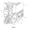
- Fig. 14 is a perspective diagram showing a gear group 33 and a rotary scale 45.
- Fig. 15 is a front view of the gear group 33.
- Fig. 16 is a planar diagram of the gear group 33 and the carriage 17
- Figs. 17A and 17B are schematic diagrams showing variations of the position of the gear with respect to the carriage 17.
- Fig. 18 is a schematic diagram showing another embodiment of the carriage.
- Fig. 19 is a perspective diagram of a transport drive roller 16.
- Fig. 20 shows cross-sectional diagrams of the transport drive roller 16, the paper support member 22, and the center support member 50.
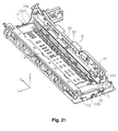
- Fig. 21 shows perspective diagrams of the main frame 8; the side frames 9, 10; the guide frame 13; and the paper support member 22.
- Fig. 22 is a diagram showing the positional relationships of the transport drive roller 16 and the transport driven roller 15.
- Figs. 23A and 23B are explanatory diagrams illustrating the principle of pushing the back edge of the paper by the transport drive roller 16 and the transport driven roller 15.
- Fig. 23A shows this embodiment.
- Fig. 23B shows a comparative example.
- Printer 1 is a so-called serial inkjet printer that alternately performs the recording operation and the paper transport operation to complete recording, is considered to be portable, and has a small-scale structure.
- Reference number 28 in Fig. 1 indicates a case that forms the exterior of the apparatus and is formed from resin material.
- Reference number 29 indicates a top cover formed from the same resin material.
- Reference number 30 indicates a front cover formed from the same resin material. The top cover 29 and the front cover 30 are formed as one body. When opened, an operating panel (not shown) and a paper feed slot (not shown) appear on the top surface of the apparatus. In addition, the paper ejection slot appears in the front surface of the apparatus.
- Reference number 30a is an operating lever (lock release lever) that releases the lock of the front cover 30.
- the hopper 4 advances and returns the supported paper P with respect to the feed roller 5 by swinging with the swinging fulcrum, which is not shown, at the center.
- the topmost sheet in the set paper P is placed in contact with the feed roller 5 by raising the hopper 4 and is fed to the downstream side by the rotation of the feed roller 5.
- the inkjet recording head 21 is provided in the carriage 17.
- the carriage 17 is loaded with an ink cartridge 20, receives power from a motor 47 ( Fig. 2 , Fig. 3 ), and reciprocally moves in the direction of the paper width (x direction).
- a motor 47 Fig. 2 , Fig. 3
- the right end in Fig. 2 and Fig. 3 in the movement region of the carriage 17 is the home position of the carriage 17.
- the home position means the standby position of the carriage 17 when there is no printing or when the power is off.
- the carriage body 18 in Fig. 4 has a first target support part (slider) 18a on the front side of the apparatus and has a second target support part 18b on the back side of the apparatus.
- the first target support unit 18a is supported by guide frame 13.
- the second target support unit 18b is supported by guide frame 12. That is, the carriage 17 is supported by guide frame 13 and guide frame 12.
- the first target support unit 18a is supported by guide frame 13 and slides on guide frame 13.
- a paper support member 22 for supporting the paper P is arranged at a position that faces the inkjet recording head 21.
- the gap between the paper P and the inkjet recording head 21 is defined by the paper support member 22.
- An ejection drive roller 25 and an ejection driven roller 26 for ejecting paper P that has been recorded are provided on the downstream side of the inkjet recording head 21 and the paper support member 22.
- Reference number 25a is the rotation shaft of the ejection drive roller 25.
- a plurality of ejection drive rollers 25 is installed at appropriate intervals along the direction of the axial line of the rotation shaft 25a (see Fig. 2 , Fig. 3 ).
- reference number 24 is a control roller that controls the paper lift.
- Fig. 2 , Fig. 3 , and Fig. 21 show the state in which the subframe 11 is removed from the state in Fig. 2 to expose the guide frame 13.
- the main frame 8 forms a shape that extends in the vertical direction as shown in Fig. 4 in a cross-sectional plane view, and the upper part is bent into the shape of the letter L on the back side of the apparatus, and the lower part is bent into the shape of the letter L on the front side of the apparatus.
- a paper feed unit that includes the hopper 4 and the feed roller 5 is installed, and various structural parts, such as the motor 47 that drives the carriage 17 or a roller support member 14 that supports the transport driven roller 15, are assembled in the main frame 8.
- the guide frame 12 extends in the vertical direction as shown in Fig. 4 in the cross-sectional plane view, and the lower part is bent to the front side of the apparatus, then bent upward, and then bent to the back side of the apparatus to form a shape resembling a hook.
- reference number 12a in Fig. 5 indicates the part that extends in the vertical direction in the cross-sectional plane view of the guide frame 12 (hereinafter, the "perpendicular part 12a").
- Reference number 12b indicates a part that extends in the horizontal direction (hereinafter, the "horizontal part 12b").
- Reference number 12c indicates a part that extends in the vertical direction (hereinafter, the "second perpendicular part 12c").
- Reference number 12d indicates a part that extends in the horizontal direction (hereinafter, the "second horizontal part 12d").
- the top surface (reference number 12e) of the horizontal unit 12b in guide frame 12 becomes a sliding surface on which a slider 18c (see Fig. 8 , Fig. 10 ) that is provided in the carriage body 18 slides.
- sliders 18d, 18e are provided in the carriage body 18.
- slider 18d is provided to be able to advance and return with respect to the slider 18e and press against the slider 18e side.
- the second vertical unit 12c becomes sandwiched by slider 18d and slider 18e.
- the sliders 18d, 18e slide with the second vertical unit 12c accompanying the movement action of the carriage 17.
- Reference number 12f indicates the sliding surface on which slider 18d slides.
- Reference number 12g indicates the sliding surface on which slider 18e slides.
- the surfaces of these sliding surfaces 12e, 12f, 12g are preferably formed to be smooth.
- the guide frame 13 provided in the front of the apparatus is formed into a hook shape by extending in the horizontal direction, bending up the end part on the front side of the apparatus, then bending horizontal to the back side of the apparatus, as shown in Fig. 4 in the cross-sectional plane view.
- reference number 13a in Fig. 6 indicates a part that extends in the horizontal direction in the cross-sectional plane view of the guide frame 13 (hereinafter, the "horizontal part 13a").
- Reference number 13b indicates a part that extends in the perpendicular direction (hereinafter, the "perpendicular part 13b").
- Reference number 13c indicates a part that extends in the horizontal direction (hereinafter, the "second horizontal part 13c").
- the top surface (reference number 13d) of the horizontal part 13a in the guide frame 13 becomes the sliding surface on which the first target support unit 18a (see Fig.8 and Fig. 10 ) provided in the carriage 17 slides. Consequently, the sliding surface 13d is preferably formed to be smooth.
- the side frames 9, 10 are in contact with the end parts of guide frames 12, 13, respectively.
- Various elements are assembled to construct the paper transport path, such as the transport drive roller 16, the ejection drive roller 25, and the paper support member 22 that were explained with reference to Fig. 2 .
- the left end part 22a shown in Fig. 21 is fixed by screws, which are not shown, to the side frame 10.
- the right end part 22b is fixed by screws 52, 52 to side frame 9. That is, the end parts in the x direction of the paper support member 22 are supported by the side frames 9, 10.
- a center part 22c that is slightly closer to the center than the right end part 22b is fixed by screws 51 to the main frame 8. That is, in the paper support member 22, the end parts in the x direction are supported by side frames 9, 10, and the interval therebetween is supported by main frame 8. Thus, bending (depressing) is effectively prevented in the x direction of the paper support member 22.
- the function of the paper support member 22 will be further explained later.
- the carriage 17 (carriage body 18) related to this embodiment is explained next with reference to Fig.7 and later drawings.
- the carriage body 18 that forms a box shape as described above constitutes the case.
- Reference number 18h in Fig. 9 is the side surface on the second direction side (hereinafter, referred to as the "left side surface") of the side surfaces that constitute the periphery of the carriage body 18.
- Reference number 18g in Fig. 10 is the side surface on the first direction side (hereinafter, referred to as the "right side surface").
- reference number 18f in Fig. 7 to Fig. 9 and Fig. 11 indicates a projecting part that projects out in the second direction (direction opposite the home position of the carriage 17).
- the projecting part 18f is a part of region A indicated in Fig. 7 and Fig. 8 in the carriage body 18 and indicates the part that projects out in the second direction side from the second target support unit 18b in the embodiment.
- the straight line Cu in Fig. 8 is a line that is parallel to the y direction and passes through the center point between two sliders 18c, 18c arranged with the predetermined interval in the carriage movement direction.
- the range ws indicates the target support region that supports the second target support unit 18b with the guide frame 12 as the support unit.
- the carriage body 18 is formed with a projecting unit 18f and forms an asymmetric shape in the carriage movement direction (x direction) with respect to the straight line Cu passing through the center position of the target support region ws.
- a belt clamp unit 18k shown in Fig. 11 is provided in the back surface side of the carriage body 18.
- the belt clamp unit 18k is a part that clamps (holds) the endless belt 48.
- the belt clamp unit 18k receives the drive power from the endless belt 48.
- the endless belt 48 passes over the entire carriage movement region, receives power from a motor 47 ( Fig. 2 , Fig. 3 ) to operate, and moves the carriage 17.
- the gear group 33 is explained as the power transmission mechanism for transmitting the power of the motor 32 ( Fig. 15 , Fig. 16 ) to the transport drive roller 16 and the ejection drive roller 25 that constitute the transport unit for transporting the paper P.
- the motor 32 is provided on the back side in the forward and backward direction of the apparatus.
- the gear group 33 is provided with a plurality of gears so that power is transmitted to the transport drive roller 16 that is positioned in the center in the forward and backward direction of the apparatus and the ejection drive roller 25 (rotation shaft 25a thereof) that is positioned on the front side in the forward and backward direction of the apparatus.
- Each gear constituting the gear group 33 is arranged in the side frame 10, more specifically, is arranged to the outside of the side frame 10 (outside of the apparatus).
- the gear group 33 is configured from gears 34, 35, 36, 37, 38, 39, 40, 41 in order from the motor 32 side as shown in Fig. 15 and Fig. 16 .
- Gear 34 is the gear arranged on the rotation shaft of the motor 32.
- Gear 37 is the gear arranged at the shaft end of the transport drive roller 16 as the first roller (first roller drive gear).
- Gear 41 is the gear arranged at the shaft end of the ejection drive roller 25 (rotation shaft 25a thereof) as the second roller (second roller drive gear).
- the gear group 33 transmits power through gear 37 to the ejection drive roller 25 (rotation shaft 25a thereof).
- the rotary scale 45 is arranged on the shaft end of the transport drive roller 16 ( Fig. 13 , Fig. 14 ).
- the rotary scale 45 configures a rotation detection unit 43 that detects the rotation of the transport drive roller 16 and is arranged so that a detection unit 44 ( Fig. 16 ) that detects the rotation of the rotary scale 45 sandwiches the outer peripheral part of the rotary scale 45.
- the rotary scale 45 and the detection unit 44 configure the rotation detection unit 43.
- a control unit, which is not shown, in the printer 1 can determine the amount of rotation and the direction of rotation of the transport drive roller 16 and the ejection drive roller 25 based on the detection signal from the rotation detection unit 43.
- Fig. 12 and Fig. 16 show the state in which the carriage 17 is positioned at the end part in the second direction.
- gears 38, 39 in this embodiment are entirely positioned below the carriage 17, and parts of gears 37, 40 are positioned below the carriage 17.
- the carriage 17 in this embodiment is provided with a projecting part 18f that projects in the second direction. Therefore, the volume of the carriage 17 can be ensured by the projecting part 18f, and at least a portion of the gear group 33 is positioned below the projecting unit 18f in the carriage 17 when moved to the end part in the second direction.
- an increase in the width dimension of the apparatus can be limited.
- an increase in the height dimension of the apparatus can be limited because the volume of the carriage can be ensured without increasing the carriage body 18 in the height direction.
- the ink cartridge 20B occupies the space that includes the projecting unit 18f in the carriage 17; therefore, the ink volume in the ink cartridge 20B can be ensured.
- the rotary scale 45 that constitutes the rotation detection unit 43 for detecting the rotation of the transport drive roller 16 as the first roller is formed with a diameter smaller than that of the gear 37 as the first roller drive gear. Due to this, the rotary scale 45 can be protected particularly from external pressure from above the apparatus.
- the rotary scale 45 is arranged on the first direction side (side frame 10 side) with respect to the gear 37. Therefore, the detection unit 44 that reads the rotary scale 45 is arranged between the gear group 33 and the side frame 10. Consequently, it is possible to prevent positioning the detection unit 44 at the outermost side of the apparatus body (outside in the carriage movement direction), and the increase in the dimensions (dimension in the carriage movement direction) of the apparatus body can be limited.
- a convex part 10a forming an arc shape that is along the outer shape of the rotary scale 45 as shown in Fig. 13 and has a diameter larger than the diameter of the rotary scale 45 is formed in the side frame 10 that supports the transport drive roller 16. Therefore, the convex part 10a has the function of a shielding wall for the rotary scale 45 and is able to prevent the adhesion of ink mist to the rotary scale 45.
- Fig. 17A is a drawing schematically showing the embodiment described above.
- the carriage body 18 moves in the direction of the arrow from the position indicated by the two-dot-dash line and positioned at the endmost part, the gear 37 enters entirely below the carriage body 18 in the carriage movement direction (x direction).
- the configuration is not limited to this embodiment and may have a portion of the gear (reference number 37a) in the carriage movement direction (x direction) enter below the carriage body 18 as shown in Fig. 17B .
- the dashed line indicated by the symbol Ln is the position of the left side surface 18h of the carriage body 18.
- reference number 18m is a concave part that is formed in the lower part on the left side of the carriage body 18.
- the concave part 18m is a concave part that is formed below the projecting unit 18f by the projecting unit 18f described above.
- the carriage body 18p shown in Fig. 18 forms a shape with right-left symmetry, which is different than the embodiment described above, in the carriage movement direction (x direction). That is, the concave part 18m and a concave part 18n on the opposite side are formed to have the same size.
- the gear 37 can be constructed to enter the concave part 18m.
- the carriage 17 in this embodiment is supported and guided in the movement direction by guide frames 12, 13, but may be supported and guided in the movement direction by the shaft.
- the transport drive roller 16 and the transport driven roller 15 are explained in further detail with reference to Fig. 19 and later drawings.
- the transport drive roller 16 is provided with a high friction layer 16a in which abrasion-resistant particles are nearly uniformly dispersed on the outer peripheral surface of the shaft body (metal core shaft or hollow metal shaft) that extends in the width direction of the paper.
- the right and left shaft ends thereof are supported by the side frames 9, 10 ( Fig. 2 ).
- the high friction layer 16a does not have to be formed in the center part of the transport drive roller 16.
- the center part is supported by a center support member 50 as shown in Fig. 19 and Fig. 20 .
- a center support member 50 By supporting the center part as well as the two end parts of the transport drive roller 16 by the center support member 50, bending of the transport drive roller 16 is suppressed, and good paper transport accuracy can be ensured.
- the center support member 50 is arranged in the paper support member 22.
- Reference number 22d in Fig. 20 is a support part that supports the center support member 50 in the paper support member 22.
- the relative positional relationship of the paper support member 22 and the transport drive roller 16 does not fluctuate over the x direction (paper width direction), namely the orientation of the paper can be stable over the x direction (paper width direction), and the degradation of the recording quality can be suppressed.
- the end parts in the x direction are supported by side frames 9, 10, and the center part 22c therebetween is supported by the main frame 8. Due to this, bending (depression) in the x direction of the paper support member 22 is effectively prevented. As a result, bending (depressing in the center part) of the transport drive roller 16 can be effectively suppressed, and better recording quality can be obtained. In addition, the gap between the inkjet recording head 21 and the paper P is stable over the x direction (paper width direction), and degradation of the recording quality can be suppressed.
- Fig. 22 illustrates the positional relationship of the transport drive roller 16 and the transport driven roller 15.
- Reference symbol Q1 indicates the shaft center position of the transport driven roller 15.
- Reference symbol Q2 indicates the shaft center position of the transport drive roller 16.
- reference symbol T indicates the contact position of the transport drive roller 16 and the transport driven roller 15.
- reference symbol Lv indicates a vertical line that passes through the shaft center position Q2.
- Reference symbol Lp indicates the straight line that passes through shaft center position Q1 and shaft center position Q2.
- Reference symbol Lh indicates the horizontal line that passes through the contact position T.
- reference symbol ⁇ indicates the angle formed by the vertical line Lv and the straight line Lp.
- reference symbol d1 indicates the diameter of the transport driven roller 15.
- Reference symbol d2 indicates the diameter of the transport drive roller 16.
- the diameter d1 of the transport driven roller 15 in the embodiment is set to be larger than the diameter d2 of the transport drive roller 16.
- the angle ⁇ is set to 0° ⁇ ⁇ ⁇ 90°
- the advancing direction of the paper P sent from between the transport drive roller 16 and the transport driven roller 15 points at an incline downward as indicated by arrow Df. Due to this, the paper P sent from between the transport drive roller 16 and the transport driven roller 15 is pushed toward the paper support member 22 ( Fig. 4 ).
- paper is kept from floating at the position opposite the inkjet recording head 21, and good recording effects are obtained.
- reference symbol Cu indicates the corner where the back edge of the paper is pushed out by the transport driven roller 15.
- Reference symbol Cd indicates the corner where the back edge of the paper is pushed out by the transport drive roller 16.
- the transport driven roller 15 is pressed toward the transport drive roller 16, namely the paper P is pressed between the transport driven roller 15 and the transport drive roller 16.
- a pushing force is received from both rollers.
- Reference symbol F1 indicates the pushing force applied by the transport driven roller 15 to the back edge corner Cu.
- Reference symbol F2 indicates the pushing force applied by the transport drive roller 16 to the back edge corner Cd.
- the pushing force F2 by the transport drive roller 16 that has the relatively smaller diameter becomes larger than the pushing force F1 by the transport driven roller 15 that has the relatively larger diameter.
- the transport driven roller 15 that acts to forcefully push out the back edge of the paper has a larger diameter than that of the transport drive roller 16 so that the pushing force F1 accompanying the pressing force is relatively small (d1 > d2).
- the pushing force F1 accompanying the pressing force is relatively small (d1 > d2).
- Fig. 23B is a diagram that illustrates a comparative example, which is the case in which the diameter of the transport driven roller 15a is set to be smaller than the diameter of the transport drive roller 16b.
- pushing force F1 shown in the drawing becomes larger than pushing force F2. Consequently, the transport driven roller 15 (capable of free rotation) that rotates so that the back edge of the paper is forcefully pushed out will forcefully push out the back edge of the paper accompanying a relatively large pushing force F1.
- the kicking phenomenon becomes evident.
Landscapes
- Engineering & Computer Science (AREA)
- Mechanical Engineering (AREA)
- Ink Jet (AREA)
- Character Spaces And Line Spaces In Printers (AREA)
- Common Mechanisms (AREA)
Abstract
Description
- This application claims priority to Japanese Patent Application No.
2013-272477 filed on December 27, 2013 2014-029769 filed on February 19, 2014 2013-272477 2014-029769 - The present invention relates to a recording apparatus represented by facsimile machines, printers, and the like.
- A so-called serial printer is a printer that completes the recording by alternately executing a paper transport operation of a predetermined amount of paper and a recording operation that accompanies the movement in the direction of the paper width of a carriage provided with a recording head. In addition, the types of inkjet printers are a type that provides an ink cartridge in the carriage and a type that provides the ink cartridge independent of the carriage and connects the ink cartridge to the carriage by an ink tube. In either type of serial printer, recording is performed by the reciprocating operation of the carriage in a predetermined range.
- In an inkjet printer, a pair of transport rollers for transporting a recording sheet, as an example of a medium, is provided on the upstream side of the recording head. The transport roller pair is usually configured from a drive roller that is driven by a motor and a driven roller that presses toward the drive roller (e.g., Japanese Laid-Open Patent Publication No.
2006-247932 - The drive roller is produced by forming a high friction layer on the outer peripheral surface of a solid metal shaft or a hollow metal shaft. The driven roller is formed by resin molding. The recording paper is transported to the downstream side by the rotational drive of the drive roller in the state in which the paper is pinched by the drive roller and the driven roller.
- Here, when the recording paper is transported by this kind of transport roller pair, the back edge of the paper is forcefully ejected when the transport roller pair releases. As a result, the phenomenon of disruption of the transport accuracy and the so-called kicking phenomenon occur. This kind of kicking phenomenon conspicuously occurs particularly with thick recording paper (e.g., glossy paper, paper board).
- In addition, there is a demand for a further reduction in printer size. In particular, users are requesting further reductions in the sizes of mobile printers that they expect to carry.
- Now, when the width dimension of the printer is examined, the width dimension is determined for the most part by the width of the movement region of the carriage, and the sizes and the placement positions of structural elements that are arranged on the outside of the movement region. Because the movement region of the carriage is determined by the paper width and cannot be reduced, a reduction of the space occupied by structural elements that are arranged outside of the carriage movement region is essential in reducing the width dimension.
- Japanese Laid-Open Patent Publication No.
2006-289770 - As a means to suppress the kicking phenomenon described above, Japanese Laid-Open Patent Publication No.
2006-247932 - However, in the structure described above in Japanese Laid-Open Patent Publication No.
2006-247932 - Also, a reduction in the height dimension, in addition to the width dimension, of the apparatus is also requested for printers. However, when the height dimension of the apparatus is reduced, the volume of the carriage becomes smaller. In particular, a smaller ink cartridge must be designed for the type that provides the ink cartridge in the carriage. Therefore, if the carriage volume is ensured while the height dimension of the apparatus is reduced, the width of the carriage must be increased, but the width dimension of the apparatus will increase. In other words, there is a trade-off relationship between the carriage volume, namely the volume of the ink cartridge, and the width dimension of the apparatus. The problem was the difficulty in establishing both.
- The present invention solves at least a portion of the problems described above and can be implemented in the following modes or embodiments.
- In order to solve the above problems, a recording apparatus related to a first embodiment of the invention is provided with a carriage including a recording head configured to record on the medium and move in a first direction and a second direction that is an opposite direction thereto, a support unit supporting the carriage, and a power transmission mechanism configured to transmit power of a drive source to a transport unit configured to transport the medium. At least a part of the power transmission mechanism is positioned below the carriage that is moved to an end part in the second direction.
- According to this embodiment, the power transmission mechanism is incorporated into the region required for the movement of the carriage because at least a part of the power transmission mechanism is positioned below the carriage when moved to the end part in the second direction. Thus, the width dimension of the apparatus can be limited, and the carriage volume can be ensured.
- A second embodiment is the first embodiment in which the carriage is provided with a projection unit that projects in the second direction, forms an asymmetric form in a movement direction with respect to the center of a target support region that is supported by the support unit in the movement direction, and at least a part of the power transmission mechanism is positioned below the projecting part of the carriage when moved to the end part in the second direction.
- According to this embodiment, because the carriage is provided with a projecting part that projects in the second direction, the volume of the carriage can be ensured by the projecting part, and at least a part of the power transmission mechanism below the projecting part of the carriage when moved to the end part in the second direction. Thus, an increase in the width direction and an increase in the height direction of the apparatus can be limited.
- A third embodiment is the first embodiment in which the carriage is provided with an ink cartridge configured to store ink, the ink cartridge is detachably arranged to the carriage, and the ink cartridge is arranged to occupy a space that includes the projecting part in the carriage.
- According to this embodiment, the ink cartridge storing the ink occupies space that includes the projecting part in the carriage; therefore, the volume of ink in the ink cartridge can be ensured.
- A fourth embodiment is any of the first to the third embodiments in which the transport unit is provided with a first roller provided on an upstream side of the recording head and a second roller provided on the downstream side of the recording head in the transport path of the medium, the power transmission mechanism includes a first roller drive gear provided in a shaft end unit of the first roller and is configured to transmit power to the second roller through the first roller drive gear, and a rotary scale that constitutes a rotation detection unit configured to detect a rotation of the first roller is provided on a side of the first direction with respect to the first roller drive gear.
- According to this embodiment, because the rotary scale is provided on the first direction side with respect to the first roller drive gear, the placement of a detection unit that reads the rotary scale on the outermost side (outside in the carriage movement direction) of the apparatus body can be avoided; and an increase in the dimensions of the apparatus body (dimension in the carriage movement direction) can be limited.
- A fifth embodiment is the fourth embodiment in which a diameter of the rotary scale is smaller than a diameter of the first roller drive gear.
- According to this embodiment, because the diameter of the rotary scale is smaller than the diameter of the first roller drive gear, the rotary scale can be protected from external pressure from above the apparatus.
- A sixth embodiment is the fourth or fifth embodiment in which a frame supporting the first roller is provided, and the frame has a convex part that is along the exterior shape of the rotary scale and has an arc shape having a diameter larger than the diameter of the rotary scale.
- According to this embodiment, because the convex part formed in the frame forms an arc shape that is along the exterior shape of the rotary scale and has a diameter larger than the diameter of the rotary scale, the convex part has the function of a shielding wall for the rotary scale and prevents ink mist from adhering to the rotary scale.
- A seventh embodiment is the sixth embodiment in which the carriage has a concave part that avoids the convex part when the carriage moved to the end part in the second direction.
- According to this embodiment, because a concave part is formed in the carriage to avoid the convex part formed in the frame when the carriage was positioned at the end part in the second direction, an increase in the width dimension of the apparatus can be limited without the need to set the position of the frame on the outside in order to ensure the movement region of the carriage (in order to prevent interference of the carriage and the frame).
- A recording apparatus related to an eighth embodiment is provided with a recording head configured to record on a medium, a drive roller configured to transport the medium to a side of the recording head and be driven by a drive source, and a driven roller that is configured to be driven to rotate while the driven roller is pressed toward the drive roller and is in contact with the medium, and that has a diameter larger than that of the drive roller.
- According to this embodiment, the diameter of the driven roller is larger than the diameter of the drive roller and obtains the following actions and effects. That is, the back end of the medium is pressed between the driven roller and the drive roller. Then for the pushing force accompanying the pressing force of the driven roller, the pushing force by the drive roller that has a relatively small diameter becomes larger than the pushing force by the driven roller that has a relatively large diameter.
- Here, when the back end of the medium is pushed out from between the driven roller and the drive roller, the rotation of the driven roller acts to forcefully push out the back end of the medium because the driven roller is capable of free rotation. However, because the drive roller is connected to the drive source and is unable to rotate freely, the drive roller does not act to forcefully push out the back end of the medium compared with the driven roller.
- In this embodiment, the driven roller that uses these properties and acts to forcefully push out the back end of the medium has a larger diameter than that of the drive roller so that the pushing force accompanying the pressing force is relatively small. Consequently, the kicking phenomenon can be appropriately suppressed with a simple structure.
- A ninth embodiment is the eighth embodiment in which a medium support member that supports the medium is provided at a position that faces the recording head, and the medium that is sent out from between the drive roller and the driven roller is pressed against the medium support member.
- According to this embodiment, the medium support member that supports the medium is provided at a position that can be opposite the recording head. The medium sent from between the drive roller and the driven roller pushes against the medium support member. Therefore, the floating up of the medium at the position opposite the recording head can be effectively suppressed.
- A tenth embodiment is the eighth or ninth embodiment in which the drive roller is formed with particles affixed to an outer peripheral surface of a solid shaft or a hollow shaft, and the driven roller is formed from resin material.
- An eleventh embodiment is any one of the eighth to the tenth embodiments in which a carriage including the recording head and configured to move in a first direction and a second direction that is an opposite direction thereto, a support unit supporting the carriage, and a power transmission mechanism t configured to transmit power of a drive source to the drive roller are further provided, and at least a part of the power transmission mechanism is positioned below the carriage when moved to an end part in the second direction.
- According to this embodiment, because at least a part of the power transmission mechanism is positioned below the carriage when moved to the end part in the second direction, the power transmission mechanism enters into the region required in carriage movement. Due to this, the width dimension of the apparatus can be limited, and the carriage capacity can be ensured.
- The twelfth embodiment is the eleventh embodiment in which an ejection roller configured to eject the medium is provided on a downstream side with respect to the recording head in a transport path of the medium. The power transmission mechanism includes a first roller drive gear provided at a shaft end unit of the drive roller and is configured to transmit power to the ejection roller through the first roller drive gear. A rotary scale that constitutes a rotation detection unit configured to detect a rotation of the drive roller is provided on a side of the first direction side with respect to the drive roller drive gear.
- According to this embodiment, because the rotary scale is provided on the first direction side with respect to the first roller drive gear, it is possible to avoid positioning the detection unit that reads the rotary scale on the outermost side of the apparatus body (outer side in the carriage movement direction) and to limit the increase in the dimensions of the apparatus body (dimension in the carriage movement direction).
- A thirteenth embodiment is the twelfth embodiment in which the diameter of the rotary scale is smaller than the diameter of the first roller drive gear.
- According to this embodiment, a diameter of the rotary scale is smaller than a diameter of the first roller drive gear. Therefore, the rotary scale can be protected from external pressure from above the apparatus.
- A fourteenth embodiment is the twelfth or thirteenth embodiment in which a frame supporting the drive roller is provided, and the frame has a convex part that has an arc shape with a diameter larger than the diameter of the rotary scale and is along an external shape of the rotary scale.
- According to this embodiment, because the convex part formed in the frame is along the outer shape of the rotary scale and has an arc shape having a diameter larger than the diameter of the rotary scale, the convex part has the function of a shielding wall for the rotary scale and prevents the adhesion of ink mist to the rotary scale.
- A fifteenth embodiment is the fourteenth embodiment in which the carriage has a concave part that avoids the convex part when the carriage was moved to the end part in the second direction.
- According to this embodiment, because the concave part formed in the carriage avoids the convex part formed in the frame when the carriage is positioned at the end part in the second direction, an increase in the width dimension of the apparatus can be limited without the need to set the position of the frame on the outside in order to ensure the movement region for the carriage (in order to prevent interference of the carriage and the frame).
- Referring now to the attached drawings which form a part of this original disclosure:
-
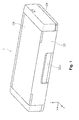
Fig. 1 is an exterior perspective diagram of a printer related to the embodiments; -
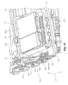
Fig. 2 is a perspective diagram of the apparatus body of a printer related to the embodiments; -
Fig. 3 is a perspective diagram of the apparatus body of a printer related to the embodiments; -
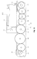
Fig. 4 is a side cross-sectional diagram showing the paper transport path of a printer related to the embodiments; -
Fig. 5 is a partial enlarged diagram ofFig. 4 ; -
Fig. 6 is a partial enlarged diagram ofFig. 4 ; -
Fig. 7 is a planar diagram viewed from above the carriage; -
Fig. 8 is a planar diagram viewed from below the carriage; -
Fig. 9 is a perspective diagram of the carriage viewed at an incline from above and in front of the apparatus; -
Fig. 10 is a perspective diagram of the carriage viewed at an incline from below and in front of the apparatus; -
Fig. 11 is a perspective diagram of the carriage viewed at an incline from above and behind the apparatus; -
Fig. 12 is a perspective diagram of the carriage when position at the end part on the left side; -
Fig. 13 is a perspective diagram of the carriage positioned slightly closer to the home position side than the end part on the left side; -
Fig. 14 is a perspective diagram showing the gear group and the rotary scale; -
Fig. 15 is a front diagram of the gear group; -
Fig. 16 is a planar diagram of the gear group and the carriage viewed from below; -
Figs. 17A and 17B are schematic diagrams showing variations in the position of the gears with respect to the carriage; -
Fig. 18 is a schematic diagram showing another embodiment of the carriage; -
Fig. 19 is a perspective diagram of the transport drive roller; -
Fig. 20 shows cross-sectional diagrams of the transport drive roller, the paper support member, and the center support member; -
Fig. 21 shows perspective diagrams of the main frame, the side frame, the guide frame, and the paper support member; -
Fig. 22 is a diagram showing the positional relationships of the transport drive roller and the transport driven roller; -
Figs. 23A and 23B are explanatory diagrams showing the principle of pushing out the back edge of the paper by the transport drive roller and the transport driven roller,Fig 23A shows the embodiment, andFig. 23B shows a comparative example. - Embodiments of the present invention are explained below with reference to the drawings. The present invention is not limited to the embodiments described below and can have various modifications within the scope of the invention described in the scope of the patent claims. With the premise that these embodiments are included in the scope of the present invention, embodiments of the present invention are explained below.
-
Fig. 1 is an exterior perspective diagram of an inkjet printer (hereinafter, referred to as the "printer") 1, which is an embodiment of the "recording apparatus" related to the present invention.Fig. 2 andFig. 3 are perspective diagrams of the apparatus body (state in which the case constituting the exterior is removed) 2 of theprinter 1.Fig. 4 is a side cross-sectional diagram showing the paper transport path of theprinter 1.Fig. 5 andFig. 6 are partial enlarged diagrams ofFig. 4 . - In addition,
Fig. 7 is a planar diagram of acarriage 17 viewed from above.Fig. 8 is a planar diagram of thecarriage 17 viewed from below.Fig. 9 is a perspective diagram of thecarriage 17 viewed at an incline in front of and above the apparatus.Fig. 10 is a perspective diagram of thecarriage 17 viewed at an incline in front of and below the apparatus.Fig. 11 is a perspective diagram of thecarriage 17 viewed at an incline behind and above the apparatus.Fig. 12 is a perspective diagram of thecarriage 17 when positioned at the end part on the left side.Fig. 13 is a perspective diagram of thecarriage 17 when positioned slightly closer to the home position side than the end part on the left side. Furthermore,Fig. 14 is a perspective diagram showing agear group 33 and arotary scale 45.Fig. 15 is a front view of thegear group 33.Fig. 16 is a planar diagram of thegear group 33 and thecarriage 17 viewed from below. -
Figs. 17A and 17B are schematic diagrams showing variations of the position of the gear with respect to thecarriage 17.Fig. 18 is a schematic diagram showing another embodiment of the carriage.Fig. 19 is a perspective diagram of atransport drive roller 16.Fig. 20 shows cross-sectional diagrams of thetransport drive roller 16, thepaper support member 22, and thecenter support member 50.Fig. 21 shows perspective diagrams of themain frame 8; the side frames 9, 10; theguide frame 13; and thepaper support member 22.Fig. 22 is a diagram showing the positional relationships of thetransport drive roller 16 and the transport drivenroller 15.Figs. 23A and 23B are explanatory diagrams illustrating the principle of pushing the back edge of the paper by thetransport drive roller 16 and the transport drivenroller 15.Fig. 23A shows this embodiment.Fig. 23B shows a comparative example. - In the x-y-z orthogonal coordinate system shown in each diagram, the x direction and the y direction are in the horizontal direction. Of these, the x direction is the direction that is orthogonal to the paper transport direction (paper width direction), is the left and right direction of the apparatus, and is the movement direction (main scanning direction) of the
carriage 17. The y direction is the paper transport direction and the depth direction of the apparatus. Furthermore, the z direction is the direction of gravity and the height direction of the apparatus. - The entire configuration of the
printer 1 is explained below with reference toFig. 1 to Fig. 5 .Printer 1 is a so-called serial inkjet printer that alternately performs the recording operation and the paper transport operation to complete recording, is considered to be portable, and has a small-scale structure.Reference number 28 inFig. 1 indicates a case that forms the exterior of the apparatus and is formed from resin material.Reference number 29 indicates a top cover formed from the same resin material.Reference number 30 indicates a front cover formed from the same resin material. Thetop cover 29 and thefront cover 30 are formed as one body. When opened, an operating panel (not shown) and a paper feed slot (not shown) appear on the top surface of the apparatus. In addition, the paper ejection slot appears in the front surface of the apparatus.Reference number 30a is an operating lever (lock release lever) that releases the lock of thefront cover 30. - The
apparatus body 2 shown inFig. 2 andFig. 3 constitutes the inside of thecase 28 described above. Theapparatus body 2 constructs a skeleton from a plurality of frames. Specifically, the body is configured from amain frame 8, aside frame 9, aside frame 10, asubframe 11, aguide frame 12, and a guide frame 13 (the details will be explained later). - The back of the apparatus has a
paper feed slot 3 in which recording paper (mainly, standard sheets of paper: hereinafter, referred to as "paper P") as an example of the medium, can be set. A plurality of sheets of paper P set in thepaper feed slot 3 is supported at an inclined orientation by ahopper 4 and a paper support, which is not shown, that are positioned in the upper part of thehopper 4. - In
Fig. 4 , thehopper 4 advances and returns the supported paper P with respect to the feed roller 5 by swinging with the swinging fulcrum, which is not shown, at the center. The topmost sheet in the set paper P is placed in contact with the feed roller 5 by raising thehopper 4 and is fed to the downstream side by the rotation of the feed roller 5. - A paper transport unit provided with the
transport drive roller 16 and the transport drivenroller 15 is arranged downstream of the feed roller 5. Paper P is transported below aninkjet recording head 21 by the rollers. Thetransport drive roller 16 is driven to rotate by a motor 32 (Fig. 15 ,Fig. 16 ) as the drive source. The transport drivenroller 15 is supported to enable free rotation by aroller support member 14 and is pressed toward thetransport drive roller 16 by an application unit (not shown) for applying a pressing force to theroller support member 14. Then, the roller comes into contact with transported paper P and is driven to rotate. Thetransport drive roller 16 is formed from a solid metal shaft or a hollow metal shaft. The transport drivenroller 15 is formed from a resin material (e.g., polyoxymethylene (POM)). Thetransport drive roller 16 and the transport drivenroller 15 are explained later in more detail. - The
inkjet recording head 21 is provided in thecarriage 17. Thecarriage 17 is loaded with an ink cartridge 20, receives power from a motor 47 (Fig. 2 ,Fig. 3 ), and reciprocally moves in the direction of the paper width (x direction). In this embodiment, the right end inFig. 2 andFig. 3 in the movement region of thecarriage 17 is the home position of thecarriage 17. Here, the home position means the standby position of thecarriage 17 when there is no printing or when the power is off. - Below, the movement direction of the
carriage 17 when thecarriage 17 is headed to the left end from the right end (home position) is set as the second direction. The movement direction of thecarriage 17 when thecarriage 17 is headed to the right end from the left end is set as the first direction. - Next, in the
carriage 17, the case body is formed from acarriage body 18 that forms a box shape, andink cartridges carriage body 18. Then ink is supplied to theinkjet recording head 21 from theink cartridges ink cartridges carriage body 18. InFig. 7 andFig. 9 toFig. 11 ,reference numbers carriage body 18 of theink cartridges - In this embodiment, the
carriage 17 is loaded with theink cartridges ink cartridges carriage 17, and theink cartridges inkjet recording head 21 are connected by ink tubes. - The
carriage body 18 inFig. 4 has a first target support part (slider) 18a on the front side of the apparatus and has a secondtarget support part 18b on the back side of the apparatus. The firsttarget support unit 18a is supported byguide frame 13. The secondtarget support unit 18b is supported byguide frame 12. That is, thecarriage 17 is supported byguide frame 13 andguide frame 12. In addition, the firsttarget support unit 18a is supported byguide frame 13 and slides onguide frame 13. - Similarly, the second
target support unit 18b is supported byguide frame 12 and slides onguide frame 12. Furthermore, theguide frame 12 specifies the position in the y direction of thecarriage 17. That is, theguide frame 12 guides thecarriage 17 in the main scanning direction. The firsttarget support unit 18a, the secondtarget support unit 18b, and the guide frames 12, 13 will be described later in detail. - Next, a
paper support member 22 for supporting the paper P is arranged at a position that faces theinkjet recording head 21. The gap between the paper P and theinkjet recording head 21 is defined by thepaper support member 22. Anejection drive roller 25 and an ejection drivenroller 26 for ejecting paper P that has been recorded are provided on the downstream side of theinkjet recording head 21 and thepaper support member 22.Reference number 25a is the rotation shaft of theejection drive roller 25. A plurality ofejection drive rollers 25 is installed at appropriate intervals along the direction of the axial line of therotation shaft 25a (seeFig. 2 ,Fig. 3 ). In addition,reference number 24 is a control roller that controls the paper lift. - Next, the frame that constitutes the skeleton of the
apparatus body 2 is explained. InFig. 2 ,Fig. 3 , andFig. 21 , themain frame 8, thesubframe 11, and the guide frames 12, 13 form a shape that extends in the width direction of the paper. Side frames 9, 10 form a shape that extends in the paper transport direction.Fig. 3 andFig. 21 show the state in which thesubframe 11 is removed from the state inFig. 2 to expose theguide frame 13. - The
main frame 8 forms a shape that extends in the vertical direction as shown inFig. 4 in a cross-sectional plane view, and the upper part is bent into the shape of the letter L on the back side of the apparatus, and the lower part is bent into the shape of the letter L on the front side of the apparatus. A paper feed unit that includes thehopper 4 and the feed roller 5 is installed, and various structural parts, such as themotor 47 that drives thecarriage 17 or aroller support member 14 that supports the transport drivenroller 15, are assembled in themain frame 8. - The
guide frame 12 extends in the vertical direction as shown inFig. 4 in the cross-sectional plane view, and the lower part is bent to the front side of the apparatus, then bent upward, and then bent to the back side of the apparatus to form a shape resembling a hook. More specifically,reference number 12a inFig. 5 indicates the part that extends in the vertical direction in the cross-sectional plane view of the guide frame 12 (hereinafter, the "perpendicular part 12a").Reference number 12b indicates a part that extends in the horizontal direction (hereinafter, the "horizontal part 12b").Reference number 12c indicates a part that extends in the vertical direction (hereinafter, the "secondperpendicular part 12c").Reference number 12d indicates a part that extends in the horizontal direction (hereinafter, the "secondhorizontal part 12d"). Thus, by forming a hook-like shape in the cross-sectional plane view, an improvement is designed for the rigidity in the lengthwise direction (paper width direction) of theguide frame 12. - The top surface (
reference number 12e) of thehorizontal unit 12b inguide frame 12 becomes a sliding surface on which aslider 18c (seeFig. 8 ,Fig. 10 ) that is provided in thecarriage body 18 slides. In addition,sliders carriage body 18. Of these,slider 18d is provided to be able to advance and return with respect to theslider 18e and press against theslider 18e side. Thus, the secondvertical unit 12c becomes sandwiched byslider 18d andslider 18e. Then, thesliders vertical unit 12c accompanying the movement action of thecarriage 17.Reference number 12f indicates the sliding surface on whichslider 18d slides.Reference number 12g indicates the sliding surface on whichslider 18e slides. Thus, the surfaces of these slidingsurfaces - In addition, the
guide frame 13 provided in the front of the apparatus is formed into a hook shape by extending in the horizontal direction, bending up the end part on the front side of the apparatus, then bending horizontal to the back side of the apparatus, as shown inFig. 4 in the cross-sectional plane view. More specifically,reference number 13a inFig. 6 indicates a part that extends in the horizontal direction in the cross-sectional plane view of the guide frame 13 (hereinafter, the "horizontal part 13a").Reference number 13b indicates a part that extends in the perpendicular direction (hereinafter, the "perpendicular part 13b").Reference number 13c indicates a part that extends in the horizontal direction (hereinafter, the "secondhorizontal part 13c"). Thus, by forming a hook-like shape in the cross-sectional plane view, an improvement is designed for the rigidity in the lengthwise direction (paper width direction) of theguide frame 13. - The top surface (
reference number 13d) of thehorizontal part 13a in theguide frame 13 becomes the sliding surface on which the firsttarget support unit 18a (seeFig.8 andFig. 10 ) provided in thecarriage 17 slides. Consequently, the slidingsurface 13d is preferably formed to be smooth. - Next, returning to
Fig. 2 ,Fig. 3 , andFig. 21 , the side frames 9, 10 are in contact with the end parts of guide frames 12, 13, respectively. Various elements are assembled to construct the paper transport path, such as thetransport drive roller 16, theejection drive roller 25, and thepaper support member 22 that were explained with reference toFig. 2 . In thepaper support member 22, theleft end part 22a shown inFig. 21 is fixed by screws, which are not shown, to theside frame 10. Theright end part 22b is fixed byscrews side frame 9. That is, the end parts in the x direction of thepaper support member 22 are supported by the side frames 9, 10. - In addition, in the
paper support member 22, acenter part 22c that is slightly closer to the center than theright end part 22b is fixed byscrews 51 to themain frame 8. That is, in thepaper support member 22, the end parts in the x direction are supported byside frames main frame 8. Thus, bending (depressing) is effectively prevented in the x direction of thepaper support member 22. The function of thepaper support member 22 will be further explained later. - The carriage 17 (carriage body 18) related to this embodiment is explained next with reference to
Fig.7 and later drawings. In thecarriage 17, thecarriage body 18 that forms a box shape as described above constitutes the case.Reference number 18h inFig. 9 is the side surface on the second direction side (hereinafter, referred to as the "left side surface") of the side surfaces that constitute the periphery of thecarriage body 18.Reference number 18g inFig. 10 is the side surface on the first direction side (hereinafter, referred to as the "right side surface"). - In addition,
reference number 18f inFig. 7 to Fig. 9 andFig. 11 indicates a projecting part that projects out in the second direction (direction opposite the home position of the carriage 17). The projectingpart 18f is a part of region A indicated inFig. 7 andFig. 8 in thecarriage body 18 and indicates the part that projects out in the second direction side from the secondtarget support unit 18b in the embodiment. - More specifically, the straight line Cu in
Fig. 8 is a line that is parallel to the y direction and passes through the center point between twosliders target support unit 18b with theguide frame 12 as the support unit. Thecarriage body 18 is formed with a projectingunit 18f and forms an asymmetric shape in the carriage movement direction (x direction) with respect to the straight line Cu passing through the center position of the target support region ws. - The reference symbol At is a triangular region enclosed by the straight lines that pass through the two
sliders carriage 17 is positioned inside this region At in the planar view. - Next, a
belt clamp unit 18k shown inFig. 11 is provided in the back surface side of thecarriage body 18. Thebelt clamp unit 18k is a part that clamps (holds) theendless belt 48. Thebelt clamp unit 18k receives the drive power from theendless belt 48. Theendless belt 48 passes over the entire carriage movement region, receives power from a motor 47 (Fig. 2 ,Fig. 3 ) to operate, and moves thecarriage 17. - Next, the
gear group 33 is explained as the power transmission mechanism for transmitting the power of the motor 32 (Fig. 15 ,Fig. 16 ) to thetransport drive roller 16 and theejection drive roller 25 that constitute the transport unit for transporting the paper P. Themotor 32 is provided on the back side in the forward and backward direction of the apparatus. Thegear group 33 is provided with a plurality of gears so that power is transmitted to thetransport drive roller 16 that is positioned in the center in the forward and backward direction of the apparatus and the ejection drive roller 25 (rotation shaft 25a thereof) that is positioned on the front side in the forward and backward direction of the apparatus. - Each gear constituting the
gear group 33 is arranged in theside frame 10, more specifically, is arranged to the outside of the side frame 10 (outside of the apparatus). Thegear group 33 is configured fromgears motor 32 side as shown inFig. 15 andFig. 16 .Gear 34 is the gear arranged on the rotation shaft of themotor 32.Gear 37 is the gear arranged at the shaft end of thetransport drive roller 16 as the first roller (first roller drive gear).Gear 41 is the gear arranged at the shaft end of the ejection drive roller 25 (rotation shaft 25a thereof) as the second roller (second roller drive gear). Thegear group 33 transmits power throughgear 37 to the ejection drive roller 25 (rotation shaft 25a thereof). - In addition to
gear 37, therotary scale 45 is arranged on the shaft end of the transport drive roller 16 (Fig. 13 ,Fig. 14 ). Therotary scale 45 configures arotation detection unit 43 that detects the rotation of thetransport drive roller 16 and is arranged so that a detection unit 44 (Fig. 16 ) that detects the rotation of therotary scale 45 sandwiches the outer peripheral part of therotary scale 45. Therotary scale 45 and thedetection unit 44 configure therotation detection unit 43. A control unit, which is not shown, in theprinter 1 can determine the amount of rotation and the direction of rotation of thetransport drive roller 16 and theejection drive roller 25 based on the detection signal from therotation detection unit 43. - In the above configuration,
Fig. 12 andFig. 16 show the state in which thecarriage 17 is positioned at the end part in the second direction. As illustrated, of the gears configuring thegear group 33, gears 38, 39 in this embodiment are entirely positioned below thecarriage 17, and parts ofgears carriage 17. - Because at least a portion of the
gear group 33 is positioned below thecarriage 17 when moved to the end part in the second direction, thegear group 33 entered into the region required in the movement of thecarriage 17. Thus, the width dimension of the apparatus can be limited. Additionally, because the width dimension of the apparatus can be limited even when the width of thecarriage 17 is ensured, the volume of thecarriage 17, namely the volumes of theink cartridges - In addition, the
carriage 17 in this embodiment is provided with a projectingpart 18f that projects in the second direction. Therefore, the volume of thecarriage 17 can be ensured by the projectingpart 18f, and at least a portion of thegear group 33 is positioned below the projectingunit 18f in thecarriage 17 when moved to the end part in the second direction. Thus, an increase in the width dimension of the apparatus can be limited. Additionally, an increase in the height dimension of the apparatus can be limited because the volume of the carriage can be ensured without increasing thecarriage body 18 in the height direction. - Then the
ink cartridge 20B occupies the space that includes the projectingunit 18f in thecarriage 17; therefore, the ink volume in theink cartridge 20B can be ensured. - In this embodiment, the
rotary scale 45 that constitutes therotation detection unit 43 for detecting the rotation of thetransport drive roller 16 as the first roller is formed with a diameter smaller than that of thegear 37 as the first roller drive gear. Due to this, therotary scale 45 can be protected particularly from external pressure from above the apparatus. Thus, therotary scale 45 is arranged on the first direction side (side frame 10 side) with respect to thegear 37. Therefore, thedetection unit 44 that reads therotary scale 45 is arranged between thegear group 33 and theside frame 10. Consequently, it is possible to prevent positioning thedetection unit 44 at the outermost side of the apparatus body (outside in the carriage movement direction), and the increase in the dimensions (dimension in the carriage movement direction) of the apparatus body can be limited. - In addition, the
rotary scale 45 easily degrades the detection precision because of weaker strength or slight deformation, and is readily connected to degradation of the recording quality. However, in this embodiment, because therotary scale 45 is arranged on the first direction side with respect to thegear 37 as the first roller drive gear (side frame 10 side), therotary scale 45 and thedetection unit 44 can be protected from external pressure from the sides of the apparatus. - In addition, a
convex part 10a forming an arc shape that is along the outer shape of therotary scale 45 as shown inFig. 13 and has a diameter larger than the diameter of therotary scale 45 is formed in theside frame 10 that supports thetransport drive roller 16. Therefore, theconvex part 10a has the function of a shielding wall for therotary scale 45 and is able to prevent the adhesion of ink mist to therotary scale 45. - A
concave part 18j is formed in thecarriage body 18 to avoid theconvex part 10a when thecarriage 17 is positioned at the end part in the second direction (Fig. 11 ). That is, when thecarriage 17 is positioned at the end part in the second direction (state shown inFig. 12 ), theconvex part 10a enters theconcave part 18j. Due to this, in order to ensure the movement region of the carriage 17 (in order to prevent interference of thecarriage body 18 and the side frame 10), the position of theside frame 10 does not have to be set on the outside, and an increase in the width dimension of the apparatus can be limited. - The embodiment described above is one example. Needless to say, the present invention is not limited to the embodiment described above. For example,
Fig. 17A is a drawing schematically showing the embodiment described above. Thecarriage body 18 moves in the direction of the arrow from the position indicated by the two-dot-dash line and positioned at the endmost part, thegear 37 enters entirely below thecarriage body 18 in the carriage movement direction (x direction). However, the configuration is not limited to this embodiment and may have a portion of the gear (reference number 37a) in the carriage movement direction (x direction) enter below thecarriage body 18 as shown inFig. 17B . The dashed line indicated by the symbol Ln is the position of theleft side surface 18h of thecarriage body 18. In addition,reference number 18m is a concave part that is formed in the lower part on the left side of thecarriage body 18. Theconcave part 18m is a concave part that is formed below the projectingunit 18f by the projectingunit 18f described above. - In addition, the
carriage body 18p shown inFig. 18 forms a shape with right-left symmetry, which is different than the embodiment described above, in the carriage movement direction (x direction). That is, theconcave part 18m and aconcave part 18n on the opposite side are formed to have the same size. When thecarriage body 18p having this kind of shape is positioned at the end part in the movement direction, thegear 37 can be constructed to enter theconcave part 18m. - In addition, the various implementation examples below can be adopted. For example, the
carriage 17 in this embodiment is supported and guided in the movement direction by guide frames 12, 13, but may be supported and guided in the movement direction by the shaft. - Next, the
transport drive roller 16 and the transport drivenroller 15 are explained in further detail with reference toFig. 19 and later drawings. InFig. 19 , thetransport drive roller 16 is provided with ahigh friction layer 16a in which abrasion-resistant particles are nearly uniformly dispersed on the outer peripheral surface of the shaft body (metal core shaft or hollow metal shaft) that extends in the width direction of the paper. The right and left shaft ends thereof are supported by the side frames 9, 10 (Fig. 2 ). - The
high friction layer 16a does not have to be formed in the center part of thetransport drive roller 16. The center part is supported by acenter support member 50 as shown inFig. 19 andFig. 20 . By supporting the center part as well as the two end parts of thetransport drive roller 16 by thecenter support member 50, bending of thetransport drive roller 16 is suppressed, and good paper transport accuracy can be ensured. - The
center support member 50 is arranged in thepaper support member 22.Reference number 22d inFig. 20 is a support part that supports thecenter support member 50 in thepaper support member 22. By having thepaper support member 22 arrange (support) thecenter support member 50 that supports the center part of thetransport drive roller 16, a bent shape (depression in the center part) of thepaper support member 22 in the x direction and the extent of bending, and the bent shape (depression in the center part) of thetransport drive roller 16 and the extent of bending can be equal for the most part. - Due to this, the relative positional relationship of the
paper support member 22 and thetransport drive roller 16 does not fluctuate over the x direction (paper width direction), namely the orientation of the paper can be stable over the x direction (paper width direction), and the degradation of the recording quality can be suppressed. - In the
paper support member 22 described above, as explained with reference toFig. 21 , the end parts in the x direction are supported byside frames center part 22c therebetween is supported by themain frame 8. Due to this, bending (depression) in the x direction of thepaper support member 22 is effectively prevented. As a result, bending (depressing in the center part) of thetransport drive roller 16 can be effectively suppressed, and better recording quality can be obtained. In addition, the gap between theinkjet recording head 21 and the paper P is stable over the x direction (paper width direction), and degradation of the recording quality can be suppressed. - Next,
Fig. 22 illustrates the positional relationship of thetransport drive roller 16 and the transport drivenroller 15. Reference symbol Q1 indicates the shaft center position of the transport drivenroller 15. Reference symbol Q2 indicates the shaft center position of thetransport drive roller 16. In addition, reference symbol T indicates the contact position of thetransport drive roller 16 and the transport drivenroller 15. Additionally, reference symbol Lv indicates a vertical line that passes through the shaft center position Q2. Reference symbol Lp indicates the straight line that passes through shaft center position Q1 and shaft center position Q2. Reference symbol Lh indicates the horizontal line that passes through the contact position T. In addition, reference symbol α indicates the angle formed by the vertical line Lv and the straight line Lp. In addition, reference symbol d1 indicates the diameter of the transport drivenroller 15. Reference symbol d2 indicates the diameter of thetransport drive roller 16. - The diameter d1 of the transport driven
roller 15 in the embodiment is set to be larger than the diameter d2 of thetransport drive roller 16. In addition, by setting the angle α to 0° < α < 90°, the advancing direction of the paper P sent from between thetransport drive roller 16 and the transport drivenroller 15 points at an incline downward as indicated by arrow Df. Due to this, the paper P sent from between thetransport drive roller 16 and the transport drivenroller 15 is pushed toward the paper support member 22 (Fig. 4 ). Thus, paper is kept from floating at the position opposite theinkjet recording head 21, and good recording effects are obtained. - The actions and effects obtained by setting diameter d1 of the transport driven
roller 15 to be larger than diameter d2 of thetransport drive roller 16 are explained below with reference toFigs. 23A and 23B . InFig. 23A , to facilitate the explanation, the angle α shown inFig. 22 is set to zero in the drawing. However, in practice, a predetermined angle α is set as shown inFig. 22 . - In
Fig. 23A shown in the embodiment, reference symbol Cu indicates the corner where the back edge of the paper is pushed out by the transport drivenroller 15. Reference symbol Cd indicates the corner where the back edge of the paper is pushed out by thetransport drive roller 16. - The transport driven
roller 15 is pressed toward thetransport drive roller 16, namely the paper P is pressed between the transport drivenroller 15 and thetransport drive roller 16. When the back edge of the paper is removed from both rollers, a pushing force is received from both rollers. Reference symbol F1 indicates the pushing force applied by the transport drivenroller 15 to the back edge corner Cu. Reference symbol F2 indicates the pushing force applied by thetransport drive roller 16 to the back edge corner Cd. In this embodiment, the pushing force F2 by thetransport drive roller 16 that has the relatively smaller diameter becomes larger than the pushing force F1 by the transport drivenroller 15 that has the relatively larger diameter. - Here, when the back edge of the paper is pushed out from between the transport driven
roller 15 and thetransport drive roller 16, the rotation R2 of the transport drivenroller 15 is free rotation and acts so that the back edge of the paper is forcefully pushed out. However, because thetransport drive roller 16 is connected to the drive source and is unable to freely rotate, the rotation R1 of thetransport drive roller 16 does not act to forcefully push out the back edge of the paper compared to the rotation R2 of the transport drivenroller 15. - In this embodiment, these properties are used, and the transport driven
roller 15 that acts to forcefully push out the back edge of the paper has a larger diameter than that of thetransport drive roller 16 so that the pushing force F1 accompanying the pressing force is relatively small (d1 > d2). As a consequence, the kicking phenomenon can be appropriately suppressed by this simple structure. - In order to compare this embodiment,
Fig. 23B is a diagram that illustrates a comparative example, which is the case in which the diameter of the transport drivenroller 15a is set to be smaller than the diameter of thetransport drive roller 16b. In this case, pushing force F1 shown in the drawing becomes larger than pushing force F2. Consequently, the transport driven roller 15 (capable of free rotation) that rotates so that the back edge of the paper is forcefully pushed out will forcefully push out the back edge of the paper accompanying a relatively large pushing force F1. Thus, the kicking phenomenon becomes evident. - By setting the diameter d1 of the transport driven
roller 15 to be larger than the diameter d2 of thetransport drive roller 16, the effect of degradation of the assembly precision of the apparatus can be reduced. That is, as explained with reference toFig. 22 , the angle α is set, and based on this, the advance direction of the paper P sent from between thetransport drive roller 16 and the transport drivenroller 15 is directed downward at an incline as indicated by arrow Df. This angle α is important from the perspective of obtaining good recording quality. - However, when the position of the transport driven
roller 15 is forward and backward in the horizontal direction due to a reduction in the assembly precision of the transport drivenroller 15, the angle α also changes with it. The rate of change of this angle α becomes larger as the diameter d1 of the transport drivenroller 15 becomes smaller. Because the diameter d1 of the transport drivenroller 15 is set to a large value in this embodiment, fluctuations in the angle α accompanying fluctuations in the position of the transport drivenroller 15 are suppressed, and good recording quality can be obtained. - In understanding the scope of the present invention, the term "comprising" and its derivatives, as used herein, are intended to be open ended terms that specify the presence of the stated features, elements, components, groups, integers, and/or steps, but do not exclude the presence of other unstated features, elements, components, groups, integers and/or steps. The foregoing also applies to words having similar meanings such as the terms, "including", "having" and their derivatives. Also, the terms "part," "section," "portion," "member" or "element" when used in the singular can have the dual meaning of a single part or a plurality of parts. Finally, terms of degree such as "substantially", "about" and "approximately" as used herein mean a reasonable amount of deviation of the modified term such that the end result is not significantly changed. For example, these terms can be construed as including a deviation of at least ± 5% of the modified term if this deviation would not negate the meaning of the word it modifies.
- While only selected embodiments have been chosen to illustrate the present invention, it will be apparent to those skilled in the art from this disclosure that various changes and modifications can be made herein without departing from the scope of the invention as defined in the appended claims. Furthermore, the foregoing descriptions of the embodiments according to the present invention are provided for illustration only, and not for the purpose of limiting the invention as defined by the appended claims.
Claims (15)
- A recording apparatus comprises:a carriage including a recording head configured to record onto a medium, the carriage being configured to move in a first direction and a second direction that is an opposite direction thereto;a support unit supporting the carriage; anda power transmission mechanism configured to transmit power of a drive source to a transport unit configured to transport the medium,at least a portion of the power transmission mechanism being positioned below the carriage when moved to an end part in the second direction.
- The recording apparatus according to claim 1, wherein
the carriage includes a projecting part that projects in the second direction and has an asymmetric shape in a movement direction with respect to a center of a target support region that is supported by the support unit in the movement direction, and
at least a portion of the power transmission mechanism is positioned below the projecting part of the carriage when moved to the end part in the second direction. - The recording apparatus according to claim 2, wherein
the carriage includes an ink cartridge configured to store ink, the ink cartridge being detachably arranged to the carriage, and
the ink cartridge is arranged to occupy a space that includes the projecting part in the carriage. - The recording apparatus according to claim 2, wherein
the transport unit includes a first roller arranged on an upstream side of the recording head and a second roller arranged on a downstream side of the recording head in a transport path of the medium,
the power transmission mechanism includes a first roller drive gear arranged at a shaft end unit of the first roller and is configured to transmit power through the first roller drive gear to the second roller, and
a rotary scale that configures a rotation detection unit configured to detect a rotation of the first roller is arranged on a side of the first direction of the first roller drive gear. - The recording apparatus according to claim 4, wherein
a diameter of the rotary scale is smaller than a diameter of the first roller drive gear. - The recording apparatus according to claim 5, further comprises
a frame supporting the first roller, wherein
the frame has a convex part that is along an exterior shape of the rotary scale and has an arc shape with a diameter larger than the diameter of the rotary scale. - The recording apparatus according to claim 6, wherein
the carriage has a concave part that avoids the convex part when the carriage is moved to the end part in the second direction. - A recording apparatus comprises:a recording head configured to record on a medium;a drive roller configured to transport the medium to a side of the recording head and be driven by a drive source; anda driven roller having a diameter larger than that of the drive roller, the driven roller being configured to be driven to rotate while the driven roller is pressed toward the drive roller and is in contact with the medium.
- The recording apparatus according to claim 8, further comprises
a medium support member supporting the medium and arranged at a position that faces the recording head, wherein
the medium that is sent out from between the drive roller and the driven roller is pressed against the medium support member. - The recording apparatus according to claim 9, wherein
the drive roller is formed with particles adhering to an outer peripheral surface of a solid shaft or a hollow shaft, and
the driven roller is formed from resin material. - The recording apparatus according to claim 10, further comprising
a carriage including a recording head and configured to move in a first direction and a second direction that is an opposite direction thereto,
a support unit supporting the carriage, and
a power transmission mechanism configured to transmit power of a drive source to the drive roller, wherein
at least a portion of the power transmission mechanism is positioned below the carriage when moved to an end part in the second direction. - The recording apparatus according to claim 11, further comprises
an ejection roller configured to eject the medium, the ejection roller being provided on a downstream side of the recording head in a transport path of the medium, wherein
the power transmission mechanism includes a first roller drive gear arranged in a shaft end unit of the drive roller and is configured to transmit power through the first roller drive gear to the ejection roller, and
a rotary scale that configures a rotation detection unit configured to detect a rotation of the driver roller is provided on a side of the first direction of the drive roller drive gear. - The recording apparatus according to claim 12, wherein
a diameter of the rotary scale is smaller than a diameter of the first roller drive gear. - The recording apparatus according to claim 13, further comprising
a frame supporting the drive roller, wherein
the frame has a convex part that is along an external shape of the rotary scale and has an arc shape with a diameter larger than the diameter of the rotary scale. - The recording apparatus according to claim 14, wherein
the carriage has a concave part that avoids the convex part when the carriage is moved to the end part in the second direction.
Applications Claiming Priority (2)
| Application Number | Priority Date | Filing Date | Title |
|---|---|---|---|
| JP2013272477A JP6288422B2 (en) | 2013-12-27 | 2013-12-27 | Recording device |
| JP2014029769A JP6429064B2 (en) | 2014-02-19 | 2014-02-19 | Recording device |
Publications (3)
| Publication Number | Publication Date |
|---|---|
| EP2889146A2 true EP2889146A2 (en) | 2015-07-01 |
| EP2889146A3 EP2889146A3 (en) | 2016-10-12 |
| EP2889146B1 EP2889146B1 (en) | 2019-04-03 |
Family
ID=52231980
Family Applications (1)
| Application Number | Title | Priority Date | Filing Date |
|---|---|---|---|
| EP14199831.0A Active EP2889146B1 (en) | 2013-12-27 | 2014-12-22 | Recording apparatus |
Country Status (3)
| Country | Link |
|---|---|
| US (2) | US20150183248A1 (en) |
| EP (1) | EP2889146B1 (en) |
| CN (1) | CN104742539B (en) |
Families Citing this family (2)
| Publication number | Priority date | Publication date | Assignee | Title |
|---|---|---|---|---|
| JP6924364B2 (en) * | 2017-04-03 | 2021-08-25 | セイコーエプソン株式会社 | Recording device |
| JP7172297B2 (en) * | 2018-08-31 | 2022-11-16 | セイコーエプソン株式会社 | inkjet printer |
Citations (2)
| Publication number | Priority date | Publication date | Assignee | Title |
|---|---|---|---|---|
| JP2006247932A (en) | 2005-03-09 | 2006-09-21 | Seiko Epson Corp | Recording medium conveying apparatus, recording apparatus, and liquid ejecting apparatus |
| JP2006289770A (en) | 2005-04-11 | 2006-10-26 | Canon Inc | Inkjet recording device |
Family Cites Families (41)
| Publication number | Priority date | Publication date | Assignee | Title |
|---|---|---|---|---|
| JPS6075063U (en) * | 1983-10-28 | 1985-05-25 | シチズン時計株式会社 | printer |
| US5184902A (en) * | 1989-11-26 | 1993-02-09 | Canon Kabushiki Kaisha | Recording apparatus having a single drive source for conveying recording means and feeding recording medium |
| US5598201A (en) * | 1994-01-31 | 1997-01-28 | Hewlett-Packard Company | Dual-resolution encoding system for high cyclic accuracy of print-medium advance in an inkjet printer |
| US5529414A (en) * | 1994-06-24 | 1996-06-25 | Alps Electric Co., Ltd. | Paper feeding apparatus for printer |
| DE69700969T2 (en) * | 1996-03-12 | 2000-07-27 | Seiko Epson Corp., Tokio/Tokyo | Motor with a drive shaft for a printer provided by several worm gears |
| JPH10235890A (en) | 1996-06-25 | 1998-09-08 | Seiko Epson Corp | ink cartridge |
| JP3295339B2 (en) | 1996-08-30 | 2002-06-24 | キヤノン株式会社 | Ink tank, holder, inkjet cartridge and cap |
| JPH10119314A (en) | 1996-08-30 | 1998-05-12 | Canon Inc | Method of connecting liquid discharge head unit, liquid discharge head unit, and liquid discharge cartridge |
| JPH10218421A (en) | 1997-02-06 | 1998-08-18 | Minolta Co Ltd | Sheet conveyer |
| EP0876923B1 (en) * | 1997-05-08 | 2002-02-06 | Seiko Epson Corporation | Printer with a movable paper guide mechanism and method of setting recording paper in such printer |
| US6224192B1 (en) | 1998-10-06 | 2001-05-01 | Hewlett-Packard Company | Inkjet printing systems using a modular print cartridge assembly |
| US6290319B1 (en) * | 1999-02-19 | 2001-09-18 | Hewlett-Packard Company | Controlling residual fine errors of dot placement in an incremental printer |
| KR100566221B1 (en) * | 1999-09-22 | 2006-03-29 | 세이코 엡슨 가부시키가이샤 | Printer having a roll paper sheet receiver |
| TW505574B (en) | 2000-01-31 | 2002-10-11 | Hewlett Packard Co | Ink container configured to establish reliable electrical connection with a receiving station |
| US6375315B1 (en) | 2000-04-11 | 2002-04-23 | Hewlett-Packard Company | Replaceable ink container for an inkjet printing system |
| US6488369B1 (en) | 2000-01-31 | 2002-12-03 | Hewlett-Packard Company | Ink container configured to establish reliable electrical and fluidic connections to a receiving station |
| US6302535B1 (en) | 2000-04-19 | 2001-10-16 | Hewlett-Packard Company | Ink container configured to establish reliable electrical connection with a receiving station |
| US6276780B1 (en) | 2000-06-19 | 2001-08-21 | Xerox Corporation | Fail-safe ink tank latching system |
| JP2002254673A (en) | 2000-12-25 | 2002-09-11 | Seiko Epson Corp | Ink cartridge for inkjet recording device |
| JP3864709B2 (en) | 2001-02-13 | 2007-01-10 | 東洋製罐株式会社 | Oxygen-absorbing container with excellent storage stability in an empty container |
| CA2379725C (en) | 2001-04-03 | 2007-06-12 | Seiko Epson Corporation | Ink cartridge |
| JP2003011448A (en) | 2001-06-29 | 2003-01-15 | Matsushita Electric Ind Co Ltd | Ink jet recorder |
| JP2003065798A (en) | 2001-08-29 | 2003-03-05 | Seiko Epson Corp | Encoder and recording apparatus provided with the encoder |
| DE60232280D1 (en) * | 2001-08-31 | 2009-06-18 | Seiko Epson Corp | recording device |
| JP2004209662A (en) | 2002-12-26 | 2004-07-29 | Sony Corp | Liquid tank |
| JP2004230803A (en) * | 2003-01-31 | 2004-08-19 | Canon Inc | Recording device |
| JP2006036483A (en) | 2004-07-28 | 2006-02-09 | Brother Ind Ltd | Image recording device |
| US7401915B2 (en) | 2004-07-28 | 2008-07-22 | Brother Kogyo Kabushiki Kaisha | Image-recording apparatus |
| JP4632432B2 (en) * | 2005-04-26 | 2011-02-16 | キヤノン株式会社 | Recording device |
| JP2007030388A (en) | 2005-07-28 | 2007-02-08 | Seiko Epson Corp | Cable wiring apparatus, recording apparatus, and liquid ejecting apparatus |
| JP4795168B2 (en) * | 2006-08-22 | 2011-10-19 | キヤノン株式会社 | Recording device |
| JP2010023458A (en) | 2008-07-24 | 2010-02-04 | Canon Inc | Ink tank and inkjet recording system |
| JP2010069752A (en) * | 2008-09-19 | 2010-04-02 | Seiko Epson Corp | Liquid jetting apparatus |
| US8215631B2 (en) * | 2010-08-30 | 2012-07-10 | Eastman Kodak Company | Pick roller retraction in a carriage printer |
| JP5773801B2 (en) * | 2011-08-19 | 2015-09-02 | キヤノン株式会社 | Ink jet recording apparatus and control method of the recording apparatus |
| JP5929049B2 (en) * | 2011-09-02 | 2016-06-01 | セイコーエプソン株式会社 | Recording device |
| US8915582B2 (en) | 2012-01-12 | 2014-12-23 | Seiko Epson Corporation | Cartridge and printing material supply system |
| US8708469B2 (en) | 2012-01-12 | 2014-04-29 | Seiko Epson Corporation | Cartridge and printing material supply system |
| CN103204006B (en) | 2012-01-12 | 2017-04-26 | 精工爱普生株式会社 | Printing apparatus and printing material supply system |
| CA2860539C (en) | 2012-01-12 | 2017-03-28 | Seiko Epson Corporation | Cartridge and printing material supply system |
| US8297739B1 (en) | 2012-03-02 | 2012-10-30 | Seiko Epson Corporation | Cartridge and printing material supply system |
-
2014
- 2014-12-19 US US14/576,940 patent/US20150183248A1/en not_active Abandoned
- 2014-12-22 EP EP14199831.0A patent/EP2889146B1/en active Active
- 2014-12-26 CN CN201410831887.9A patent/CN104742539B/en active Active
-
2017
- 2017-06-08 US US15/617,458 patent/US10016994B2/en active Active
Patent Citations (2)
| Publication number | Priority date | Publication date | Assignee | Title |
|---|---|---|---|---|
| JP2006247932A (en) | 2005-03-09 | 2006-09-21 | Seiko Epson Corp | Recording medium conveying apparatus, recording apparatus, and liquid ejecting apparatus |
| JP2006289770A (en) | 2005-04-11 | 2006-10-26 | Canon Inc | Inkjet recording device |
Also Published As
| Publication number | Publication date |
|---|---|
| CN104742539A (en) | 2015-07-01 |
| US20150183248A1 (en) | 2015-07-02 |
| US10016994B2 (en) | 2018-07-10 |
| US20170267004A1 (en) | 2017-09-21 |
| EP2889146B1 (en) | 2019-04-03 |
| EP2889146A3 (en) | 2016-10-12 |
| CN104742539B (en) | 2017-12-08 |
Similar Documents
| Publication | Publication Date | Title |
|---|---|---|
| JP4244960B2 (en) | Inkjet recording device | |
| EP2784013A2 (en) | Recording apparatus | |
| CN202716565U (en) | Conveyer and ink jet-recording apparatus | |
| CN102211471B (en) | Roll paper printer | |
| US10016994B2 (en) | Recording apparatus | |
| JP5573700B2 (en) | Conveying apparatus and inkjet recording apparatus | |
| EP1803574A1 (en) | Inkjet recording device and driving unit provided therein | |
| JP5494506B2 (en) | Image recording device | |
| US8746696B2 (en) | Sheet conveying device and image recording apparatus | |
| JP4985678B2 (en) | Image recording device | |
| JP5673126B2 (en) | Image recording device | |
| JP4265593B2 (en) | Inkjet recording device | |
| JP5614303B2 (en) | Image recording device | |
| JP4518160B2 (en) | Sheet conveying apparatus and image recording apparatus | |
| JP6429064B2 (en) | Recording device | |
| JP5828230B2 (en) | Image recording device | |
| JP6307955B2 (en) | Recording device | |
| US9550384B2 (en) | Recording apparatus | |
| JP6376016B2 (en) | Feeding device and image recording device | |
| JP4492673B2 (en) | Image recording device | |
| TW201932399A (en) | Medium discharge device and recording apparatus | |
| JP4888310B2 (en) | Platen for inkjet recording apparatus and inkjet recording apparatus | |
| JP2008188786A (en) | Inkjet recording device | |
| CN102416779B (en) | Conveying device and tape deck | |
| JP2012066406A (en) | Image recording device |
Legal Events
| Date | Code | Title | Description |
|---|---|---|---|
| PUAI | Public reference made under article 153(3) epc to a published international application that has entered the european phase |
Free format text: ORIGINAL CODE: 0009012 |
|
| 17P | Request for examination filed |
Effective date: 20141222 |
|
| AK | Designated contracting states |
Kind code of ref document: A2 Designated state(s): AL AT BE BG CH CY CZ DE DK EE ES FI FR GB GR HR HU IE IS IT LI LT LU LV MC MK MT NL NO PL PT RO RS SE SI SK SM TR |
|
| AX | Request for extension of the european patent |
Extension state: BA ME |
|
| PUAL | Search report despatched |
Free format text: ORIGINAL CODE: 0009013 |
|
| AK | Designated contracting states |
Kind code of ref document: A3 Designated state(s): AL AT BE BG CH CY CZ DE DK EE ES FI FR GB GR HR HU IE IS IT LI LT LU LV MC MK MT NL NO PL PT RO RS SE SI SK SM TR |
|
| AX | Request for extension of the european patent |
Extension state: BA ME |
|
| RIC1 | Information provided on ipc code assigned before grant |
Ipc: B41J 11/00 20060101ALI20160908BHEP Ipc: B41J 29/38 20060101AFI20160908BHEP Ipc: B65H 1/00 20060101ALI20160908BHEP |
|
| STAA | Information on the status of an ep patent application or granted ep patent |
Free format text: STATUS: REQUEST FOR EXAMINATION WAS MADE |
|
| R17P | Request for examination filed (corrected) |
Effective date: 20170301 |
|
| RBV | Designated contracting states (corrected) |
Designated state(s): AL AT BE BG CH CY CZ DE DK EE ES FI FR GB GR HR HU IE IS IT LI LT LU LV MC MK MT NL NO PL PT RO RS SE SI SK SM TR |
|
| STAA | Information on the status of an ep patent application or granted ep patent |
Free format text: STATUS: EXAMINATION IS IN PROGRESS |
|
| 17Q | First examination report despatched |
Effective date: 20180220 |
|
| GRAP | Despatch of communication of intention to grant a patent |
Free format text: ORIGINAL CODE: EPIDOSNIGR1 |
|
| STAA | Information on the status of an ep patent application or granted ep patent |
Free format text: STATUS: GRANT OF PATENT IS INTENDED |
|
| INTG | Intention to grant announced |
Effective date: 20181011 |
|
| RIN1 | Information on inventor provided before grant (corrected) |
Inventor name: OKAZAWA, YOSHIYUKI Inventor name: HARADA, KAZUMASA |
|
| GRAS | Grant fee paid |
Free format text: ORIGINAL CODE: EPIDOSNIGR3 |
|
| GRAA | (expected) grant |
Free format text: ORIGINAL CODE: 0009210 |
|
| STAA | Information on the status of an ep patent application or granted ep patent |
Free format text: STATUS: THE PATENT HAS BEEN GRANTED |
|
| RIN1 | Information on inventor provided before grant (corrected) |
Inventor name: HARADA, KAZUMASA Inventor name: OKAZAWA, YOSHIYUKI |
|
| AK | Designated contracting states |
Kind code of ref document: B1 Designated state(s): AL AT BE BG CH CY CZ DE DK EE ES FI FR GB GR HR HU IE IS IT LI LT LU LV MC MK MT NL NO PL PT RO RS SE SI SK SM TR |
|
| REG | Reference to a national code |
Ref country code: GB Ref legal event code: FG4D |
|
| REG | Reference to a national code |
Ref country code: CH Ref legal event code: EP Ref country code: AT Ref legal event code: REF Ref document number: 1115228 Country of ref document: AT Kind code of ref document: T Effective date: 20190415 |
|
| REG | Reference to a national code |
Ref country code: DE Ref legal event code: R096 Ref document number: 602014043947 Country of ref document: DE |
|
| REG | Reference to a national code |
Ref country code: IE Ref legal event code: FG4D |
|
| REG | Reference to a national code |
Ref country code: NL Ref legal event code: MP Effective date: 20190403 |
|
| REG | Reference to a national code |
Ref country code: LT Ref legal event code: MG4D |
|
| REG | Reference to a national code |
Ref country code: AT Ref legal event code: MK05 Ref document number: 1115228 Country of ref document: AT Kind code of ref document: T Effective date: 20190403 |
|
| PG25 | Lapsed in a contracting state [announced via postgrant information from national office to epo] |
Ref country code: NL Free format text: LAPSE BECAUSE OF FAILURE TO SUBMIT A TRANSLATION OF THE DESCRIPTION OR TO PAY THE FEE WITHIN THE PRESCRIBED TIME-LIMIT Effective date: 20190403 |
|
| PG25 | Lapsed in a contracting state [announced via postgrant information from national office to epo] |
Ref country code: LT Free format text: LAPSE BECAUSE OF FAILURE TO SUBMIT A TRANSLATION OF THE DESCRIPTION OR TO PAY THE FEE WITHIN THE PRESCRIBED TIME-LIMIT Effective date: 20190403 Ref country code: HR Free format text: LAPSE BECAUSE OF FAILURE TO SUBMIT A TRANSLATION OF THE DESCRIPTION OR TO PAY THE FEE WITHIN THE PRESCRIBED TIME-LIMIT Effective date: 20190403 Ref country code: SE Free format text: LAPSE BECAUSE OF FAILURE TO SUBMIT A TRANSLATION OF THE DESCRIPTION OR TO PAY THE FEE WITHIN THE PRESCRIBED TIME-LIMIT Effective date: 20190403 Ref country code: PT Free format text: LAPSE BECAUSE OF FAILURE TO SUBMIT A TRANSLATION OF THE DESCRIPTION OR TO PAY THE FEE WITHIN THE PRESCRIBED TIME-LIMIT Effective date: 20190803 Ref country code: NO Free format text: LAPSE BECAUSE OF FAILURE TO SUBMIT A TRANSLATION OF THE DESCRIPTION OR TO PAY THE FEE WITHIN THE PRESCRIBED TIME-LIMIT Effective date: 20190703 Ref country code: FI Free format text: LAPSE BECAUSE OF FAILURE TO SUBMIT A TRANSLATION OF THE DESCRIPTION OR TO PAY THE FEE WITHIN THE PRESCRIBED TIME-LIMIT Effective date: 20190403 Ref country code: AL Free format text: LAPSE BECAUSE OF FAILURE TO SUBMIT A TRANSLATION OF THE DESCRIPTION OR TO PAY THE FEE WITHIN THE PRESCRIBED TIME-LIMIT Effective date: 20190403 Ref country code: CZ Free format text: LAPSE BECAUSE OF FAILURE TO SUBMIT A TRANSLATION OF THE DESCRIPTION OR TO PAY THE FEE WITHIN THE PRESCRIBED TIME-LIMIT Effective date: 20190403 Ref country code: ES Free format text: LAPSE BECAUSE OF FAILURE TO SUBMIT A TRANSLATION OF THE DESCRIPTION OR TO PAY THE FEE WITHIN THE PRESCRIBED TIME-LIMIT Effective date: 20190403 |
|
| PG25 | Lapsed in a contracting state [announced via postgrant information from national office to epo] |
Ref country code: BG Free format text: LAPSE BECAUSE OF FAILURE TO SUBMIT A TRANSLATION OF THE DESCRIPTION OR TO PAY THE FEE WITHIN THE PRESCRIBED TIME-LIMIT Effective date: 20190703 Ref country code: LV Free format text: LAPSE BECAUSE OF FAILURE TO SUBMIT A TRANSLATION OF THE DESCRIPTION OR TO PAY THE FEE WITHIN THE PRESCRIBED TIME-LIMIT Effective date: 20190403 Ref country code: RS Free format text: LAPSE BECAUSE OF FAILURE TO SUBMIT A TRANSLATION OF THE DESCRIPTION OR TO PAY THE FEE WITHIN THE PRESCRIBED TIME-LIMIT Effective date: 20190403 Ref country code: PL Free format text: LAPSE BECAUSE OF FAILURE TO SUBMIT A TRANSLATION OF THE DESCRIPTION OR TO PAY THE FEE WITHIN THE PRESCRIBED TIME-LIMIT Effective date: 20190403 Ref country code: GR Free format text: LAPSE BECAUSE OF FAILURE TO SUBMIT A TRANSLATION OF THE DESCRIPTION OR TO PAY THE FEE WITHIN THE PRESCRIBED TIME-LIMIT Effective date: 20190704 |
|
| PG25 | Lapsed in a contracting state [announced via postgrant information from national office to epo] |
Ref country code: AT Free format text: LAPSE BECAUSE OF FAILURE TO SUBMIT A TRANSLATION OF THE DESCRIPTION OR TO PAY THE FEE WITHIN THE PRESCRIBED TIME-LIMIT Effective date: 20190403 Ref country code: IS Free format text: LAPSE BECAUSE OF FAILURE TO SUBMIT A TRANSLATION OF THE DESCRIPTION OR TO PAY THE FEE WITHIN THE PRESCRIBED TIME-LIMIT Effective date: 20190803 |
|
| REG | Reference to a national code |
Ref country code: DE Ref legal event code: R097 Ref document number: 602014043947 Country of ref document: DE |
|
| PG25 | Lapsed in a contracting state [announced via postgrant information from national office to epo] |
Ref country code: RO Free format text: LAPSE BECAUSE OF FAILURE TO SUBMIT A TRANSLATION OF THE DESCRIPTION OR TO PAY THE FEE WITHIN THE PRESCRIBED TIME-LIMIT Effective date: 20190403 Ref country code: SK Free format text: LAPSE BECAUSE OF FAILURE TO SUBMIT A TRANSLATION OF THE DESCRIPTION OR TO PAY THE FEE WITHIN THE PRESCRIBED TIME-LIMIT Effective date: 20190403 Ref country code: DK Free format text: LAPSE BECAUSE OF FAILURE TO SUBMIT A TRANSLATION OF THE DESCRIPTION OR TO PAY THE FEE WITHIN THE PRESCRIBED TIME-LIMIT Effective date: 20190403 Ref country code: EE Free format text: LAPSE BECAUSE OF FAILURE TO SUBMIT A TRANSLATION OF THE DESCRIPTION OR TO PAY THE FEE WITHIN THE PRESCRIBED TIME-LIMIT Effective date: 20190403 |
|
| PLBE | No opposition filed within time limit |
Free format text: ORIGINAL CODE: 0009261 |
|
| STAA | Information on the status of an ep patent application or granted ep patent |
Free format text: STATUS: NO OPPOSITION FILED WITHIN TIME LIMIT |
|
| PG25 | Lapsed in a contracting state [announced via postgrant information from national office to epo] |
Ref country code: SM Free format text: LAPSE BECAUSE OF FAILURE TO SUBMIT A TRANSLATION OF THE DESCRIPTION OR TO PAY THE FEE WITHIN THE PRESCRIBED TIME-LIMIT Effective date: 20190403 Ref country code: IT Free format text: LAPSE BECAUSE OF FAILURE TO SUBMIT A TRANSLATION OF THE DESCRIPTION OR TO PAY THE FEE WITHIN THE PRESCRIBED TIME-LIMIT Effective date: 20190403 |
|
| 26N | No opposition filed |
Effective date: 20200106 |
|
| PG25 | Lapsed in a contracting state [announced via postgrant information from national office to epo] |
Ref country code: TR Free format text: LAPSE BECAUSE OF FAILURE TO SUBMIT A TRANSLATION OF THE DESCRIPTION OR TO PAY THE FEE WITHIN THE PRESCRIBED TIME-LIMIT Effective date: 20190403 |
|
| PG25 | Lapsed in a contracting state [announced via postgrant information from national office to epo] |
Ref country code: SI Free format text: LAPSE BECAUSE OF FAILURE TO SUBMIT A TRANSLATION OF THE DESCRIPTION OR TO PAY THE FEE WITHIN THE PRESCRIBED TIME-LIMIT Effective date: 20190403 |
|
| REG | Reference to a national code |
Ref country code: CH Ref legal event code: PL |
|
| REG | Reference to a national code |
Ref country code: BE Ref legal event code: MM Effective date: 20191231 |
|
| PG25 | Lapsed in a contracting state [announced via postgrant information from national office to epo] |
Ref country code: MC Free format text: LAPSE BECAUSE OF FAILURE TO SUBMIT A TRANSLATION OF THE DESCRIPTION OR TO PAY THE FEE WITHIN THE PRESCRIBED TIME-LIMIT Effective date: 20190403 |
|
| PG25 | Lapsed in a contracting state [announced via postgrant information from national office to epo] |
Ref country code: LU Free format text: LAPSE BECAUSE OF NON-PAYMENT OF DUE FEES Effective date: 20191222 Ref country code: IE Free format text: LAPSE BECAUSE OF NON-PAYMENT OF DUE FEES Effective date: 20191222 |
|
| PG25 | Lapsed in a contracting state [announced via postgrant information from national office to epo] |
Ref country code: LI Free format text: LAPSE BECAUSE OF NON-PAYMENT OF DUE FEES Effective date: 20191231 Ref country code: BE Free format text: LAPSE BECAUSE OF NON-PAYMENT OF DUE FEES Effective date: 20191231 Ref country code: CH Free format text: LAPSE BECAUSE OF NON-PAYMENT OF DUE FEES Effective date: 20191231 |
|
| PG25 | Lapsed in a contracting state [announced via postgrant information from national office to epo] |
Ref country code: CY Free format text: LAPSE BECAUSE OF FAILURE TO SUBMIT A TRANSLATION OF THE DESCRIPTION OR TO PAY THE FEE WITHIN THE PRESCRIBED TIME-LIMIT Effective date: 20190403 |
|
| PG25 | Lapsed in a contracting state [announced via postgrant information from national office to epo] |
Ref country code: HU Free format text: LAPSE BECAUSE OF FAILURE TO SUBMIT A TRANSLATION OF THE DESCRIPTION OR TO PAY THE FEE WITHIN THE PRESCRIBED TIME-LIMIT; INVALID AB INITIO Effective date: 20141222 Ref country code: MT Free format text: LAPSE BECAUSE OF FAILURE TO SUBMIT A TRANSLATION OF THE DESCRIPTION OR TO PAY THE FEE WITHIN THE PRESCRIBED TIME-LIMIT Effective date: 20190403 |
|
| PG25 | Lapsed in a contracting state [announced via postgrant information from national office to epo] |
Ref country code: MK Free format text: LAPSE BECAUSE OF FAILURE TO SUBMIT A TRANSLATION OF THE DESCRIPTION OR TO PAY THE FEE WITHIN THE PRESCRIBED TIME-LIMIT Effective date: 20190403 |
|
| PGFP | Annual fee paid to national office [announced via postgrant information from national office to epo] |
Ref country code: DE Payment date: 20251028 Year of fee payment: 12 |
|
| PGFP | Annual fee paid to national office [announced via postgrant information from national office to epo] |
Ref country code: GB Payment date: 20251030 Year of fee payment: 12 |
|
| PGFP | Annual fee paid to national office [announced via postgrant information from national office to epo] |
Ref country code: FR Payment date: 20251117 Year of fee payment: 12 |