EP2888976A1 - Device for handling a bed structure - Google Patents
Device for handling a bed structure Download PDFInfo
- Publication number
- EP2888976A1 EP2888976A1 EP14004085.8A EP14004085A EP2888976A1 EP 2888976 A1 EP2888976 A1 EP 2888976A1 EP 14004085 A EP14004085 A EP 14004085A EP 2888976 A1 EP2888976 A1 EP 2888976A1
- Authority
- EP
- European Patent Office
- Prior art keywords
- shaft
- belts
- frame
- belt
- anchored
- Prior art date
- Legal status (The legal status is an assumption and is not a legal conclusion. Google has not performed a legal analysis and makes no representation as to the accuracy of the status listed.)
- Granted
Links
- 238000004804 winding Methods 0.000 claims abstract description 4
- 230000002411 adverse Effects 0.000 description 1
- 230000008878 coupling Effects 0.000 description 1
- 238000010168 coupling process Methods 0.000 description 1
- 238000005859 coupling reaction Methods 0.000 description 1
- 230000001419 dependent effect Effects 0.000 description 1
- 238000003780 insertion Methods 0.000 description 1
- 230000037431 insertion Effects 0.000 description 1
- 230000000087 stabilizing effect Effects 0.000 description 1
Images


Classifications
-
- A—HUMAN NECESSITIES
- A47—FURNITURE; DOMESTIC ARTICLES OR APPLIANCES; COFFEE MILLS; SPICE MILLS; SUCTION CLEANERS IN GENERAL
- A47C—CHAIRS; SOFAS; BEDS
- A47C17/00—Sofas; Couches; Beds
- A47C17/84—Suspended beds, e.g. suspended from ceiling
-
- B—PERFORMING OPERATIONS; TRANSPORTING
- B66—HOISTING; LIFTING; HAULING
- B66D—CAPSTANS; WINCHES; TACKLES, e.g. PULLEY BLOCKS; HOISTS
- B66D1/00—Rope, cable, or chain winding mechanisms; Capstans
- B66D1/28—Other constructional details
- B66D1/30—Rope, cable, or chain drums or barrels
- B66D1/34—Attachment of ropes or cables to drums or barrels
-
- B—PERFORMING OPERATIONS; TRANSPORTING
- B66—HOISTING; LIFTING; HAULING
- B66F—HOISTING, LIFTING, HAULING OR PUSHING, NOT OTHERWISE PROVIDED FOR, e.g. DEVICES WHICH APPLY A LIFTING OR PUSHING FORCE DIRECTLY TO THE SURFACE OF A LOAD
- B66F7/00—Lifting frames, e.g. for lifting vehicles; Platform lifts
- B66F7/02—Lifting frames, e.g. for lifting vehicles; Platform lifts with platforms suspended from ropes, cables, or chains or screws and movable along pillars
Abstract
Description
- The present invention relates to a lifting device for bed frames, in particular for passenger compartments or cabins of vehicles such as campers, motor homes, caravans, boats and the like.
- It is known that in vehicles of the type mentioned above there is the need to have a bed in a lowered position of use and respectively in a raised stowage position to occupy the space in the cabin destined to the bed only when necessary.
- The main purpose of the present invention is to propose a lifting device for bed frames, especially for so-called recreational vehicles, which allows to raise and lower the frame of a bed in a simple and safe way, without, however, adversely affect the overall dimensions, weight and cost of the device.
- This result is achieved, according to the present invention, by adopting the idea of providing a device having the characteristics indicated in
claim 1. Other features of the invention are the subject of the dependent claims. - Reaching the intended purpose, the present invention provides a lifting mechanism that is simple both for what regards its structure and for what concerns the use, safe, reliable and inexpensive in relation to the advantages offered. These and other advantages and characteristics of the present invention will be best understood by anyone skilled in the art thanks to the following description and to the attached drawings, provided by way of example but not to be considered in a limiting sense, wherein:
-
Fig.1 is a schematic bottom view of a device according to the present invention; -
Fig.2 is a section view along line B.B ofFig.1 ; -
Fig.3 is a schematic perspective view of the device shown inFig.1 andFig.2 , wherein there are shown four tracks of a system for keeping the bed vertically guided; -
Fig.4 4 shows the detail "A" ofFig. 3 in an enlarged view; -
Fig. 5 shows the detail "C" ofFig. 2 in an enlarged view; -
Fig.6 shows due belt portions virtually isolated from the winding/unwinding shaft; -
Fig.7 shows the belt portions ofFig.6 virtually separated from each other; -
Fig.8 shows the detail "D" ofFig.3 in an enlarged view; -
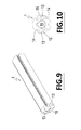
Fig.9 is a schematic perspective view of the shaft (1); -
Fig.10 is a schematic cross-section view of the shaft shown inFig.9 ; -
Fig.11 is another enlarged detail ofFig.3 ; -
Fig.12 shows the detail "E" ofFig. 2 in an enlarged view. - As said above, a device in accordance with the present invention can be used for lifting and lowering a bed, i.e. the bed base or frame (R) forming the base of the bed on which a mattress (not shown in the drawings) is supported inside the cabin of a recreational vehicle (not shown in the drawings).
- Reduced to its basic structure and with reference to the attached drawings, a device according to the present invention comprises a shaft (1) that is driven by an electric gearmotor (10), four belts (2, 3, 4, 5), i.e. two pairs of belts (2, 3; 4, 5) being anchored to said shaft. The gearmotor (10) is connected with suitable actuation push-buttons (not shown in the drawings).
- Each of said belts has an end (first end) anchored on the shaft (1) and another end anchored at a corresponding fixed point of the vehicle cabin (21, 31, 41, 51), that is a point located at a predetermined height.
- With reference to
Figs. 6 and 7 , the ends of the belts (2) and (3) destined to be anchored to the shaft (1) are denoted by reference numerals "20" and "30" respectively. - The ends of the shaft (1) are in corresponding seats (11) provided on the inner face of the longer sides of the frame (R).
- The said fixed points (21, 31, 41, 51) correspond to the vertices of an ideal quadrilateral which extends transversely to the cabin of the vehicle and consist of four identical brackets, fixed to the corresponding inner walls of the vehicle cab. Each of said brackets (21, 31, 41, 51) has a vertical surface (U) and two side arms (X). The vertical surface (U) is placed against the respective wall of the cab when the device is assembled. Between the arms (X) of each bracket there is a transverse pin (P) on which it is invested a slot (Q) formed by the end (second end) of the respective belt (2, 3, 4, 5) opposite to the end anchored on the shaft (1). In this way, the second end of each belt (2, 3, 4, 5) is fixed to the respective bracket (21, 31, 41, 51), while the first end is fixed on the shaft (1). In practice, the second end of each belt is folded on itself and sewn to form the above-mentioned slot (Q).
- On the short sides (CR) of the frame (R) there are two appendixes (12), oriented parallel to the long sides (LR) of the same frame and intended to slide in two corresponding vertical guides (6) also fixed to the cabin of the vehicle. In this way, it is possible to stabilize the movement of the frame (R) when the latter is lowered or lifted.
- On each belt (2, 3, 4, 5) there is an "L"-shaped bracket (23, 33, 43, 53) having a wing (W) that supports the frame (R). Each bracket (23, 33, 43, 53) has a slot (T) allowing the passage of the respective belt (2, 3, 4, 5). In practice, each belt (2, 3, 4, 5) can slide in the slot (T) of the respective bracket when it is wound on the shaft (1), or unwound, as further disclosed below.
- The shaft (1) has two longitudinal grooves (13) on diametrically opposite positions in which the first ends of the belts (2, 3, 4, 5) can be inserted. Each groove (13) is shaped as a pocket with a front opening (14) that facilitates the insertion of the first ends of the belts (2, 3, 4, 5) and an inner part (15) having a wider cross section so as to form a seat that is closed on three sides and is in communication with the opening (14). According to the example shown in the drawings, the grooves (13) are two in number and are diametrically opposite to each other, with the front opening (14) of a groove turned upwards and the opening (14) of the other groove turned downwards, such that said pockets are oriented along two opposite directions.
- Furthermore, the shaft (1) has a central bore (16) allowing its coaxial coupling with the output shaft of the gearmotor (10). However, the shaft (1) can be moved in any other suitable way.
- By operating the gearmotor (10), that is, by rotating the shaft (1) in the clockwise or anticlockwise direction about the respective longitudinal axis (y-y), the belts (2, 3, 4, 5) are subject to winding on the shaft (1), or unwinding, and, therefore, the brackets (23, 33, 43, 53) and the frame (R) are lifted or lowered. As previously said, the four belts (2, 3, 4, 5) are arranged so as to form two pairs (2, 3) and (4, 5), in which the belts (2, 3; 4, 5) of each pair are oriented parallel to a side (LR) of the frame (R). Each pair of belts (2, 3; 4, 5) is connected with a respective first end on the shaft (1) and with a respective second end to a corresponding fixed point (21, 31; 41, 51). A first portion of each belt is wound on the shaft (1) while a second portion of each belt is comprised between the first portion (portion wound on the shaft 1) and the respective fixed anchorage point. In accordance with the present invention, the belts of each of said pairs of belts (2, 3; 4, 5) have their respective portions wound on the shaft (1) on each other and coaxially to the same shaft (1).
- With reference to the example shown in the accompanying drawings, in which the device comprises two pairs of belts (2, 3; 4, 5), there are two pairs of coaxial portions of belts wound on the shaft (1). In
Fig. 7 the coaxial portions of the belts (2) and (3) are indicated by the references (21) and (31) respectively. - This arrangement of the belts used for moving the frame (R) ensures a greater compactness in the transverse direction and allows to have the belts of each pair along a same direction instead of being arranged side by side as in conventional devices. In addition, it is ensured a greater flexibility in the positioning of the stabilizing guides.
- In practice the details of execution may vary in any equivalent way as for what concerns the shape, arrangement and number of the individual elements described, without departing from the scope of the claimed solution and thus remaining within the limits of the protection granted by this patent.
Claims (5)
- Device for handling a bed structure, comprising a base or frame (R) on which a mattress can be placed and a shaft (1) driven by a motor unit (10) and on which there are anchored a plurality of pairs of belts (2, 3, 4, 5), wherein the two belts (2, 3, 4, 5) of each pair of belts are oriented parallel to a side of the base or frame (R), wherein each of said belts has a first end anchored on said shaft (1) and a second end connected to a corresponding fixed anchorage point (21, 31, 41 , 51), i.e. anchored to a point (21, 31, 41, 51) placed at a predetermined height, wherein the said shaft (1) is secured to said base or frame (R), wherein the clockwise or counterclockwise rotation of the shaft (1) about its own axis (y-y) determines the winding of the belts (2, 3 , 4, 5) on the same shaft (1) or their unwinding and a first portion of each belt is wound on the shaft (1) while a second portion of each belt is comprised between the first portion wound on the shaft (1) and the respective fixed anchorage point, device characterized by the fact that the belts of each of said pairs of belts (2, 3, 4, 5) have their respective portions wound on the shaft (1) on each other and coaxially to the same shaft (1).
- Device according to claim 1, characterized in that said shaft (1) is provided with longitudinal grooves (13) inside which the first end of each belt (2, 3, 4, 5) is secured.
- Device according to claim 2, characterized in that said longitudinal grooves (13) are two in number and are provided on diametrically opposite positions.
- Device according to claim 1, characterized in that on the second end of each of said belts (2, 3, 4, 5) is formed a slot (Q) inserted on a respective pin (P) in the corresponding fixed point (21, 31, 41, 51).
- Device according to one or more of the preceding claims, characterized in that said belts (2, 3, 4, 5) are four in number and they form two pairs of belts (2, 3; 4, 5).
Applications Claiming Priority (1)
| Application Number | Priority Date | Filing Date | Title |
|---|---|---|---|
| IT000306A ITFI20130306A1 (en) | 2013-12-27 | 2013-12-27 | DEVICE FOR MOVING BED STRUCTURES. |
Publications (2)
| Publication Number | Publication Date |
|---|---|
| EP2888976A1 true EP2888976A1 (en) | 2015-07-01 |
| EP2888976B1 EP2888976B1 (en) | 2015-10-07 |
Family
ID=50073279
Family Applications (1)
| Application Number | Title | Priority Date | Filing Date |
|---|---|---|---|
| EP14004085.8A Active EP2888976B1 (en) | 2013-12-27 | 2014-12-03 | Device for handling a bed structure |
Country Status (2)
| Country | Link |
|---|---|
| EP (1) | EP2888976B1 (en) |
| IT (1) | ITFI20130306A1 (en) |
Cited By (3)
| Publication number | Priority date | Publication date | Assignee | Title |
|---|---|---|---|---|
| ITUB20153427A1 (en) * | 2015-09-04 | 2017-03-04 | St La Srl | Device for balanced vertical movement of a suspended bed |
| US11510830B2 (en) * | 2020-03-04 | 2022-11-29 | Autochair Limited | Hoist mechanism |
| US11882384B2 (en) | 2021-07-27 | 2024-01-23 | Zoom Video Communications, Inc. | Identification of audio conference participants |
Families Citing this family (3)
| Publication number | Priority date | Publication date | Assignee | Title |
|---|---|---|---|---|
| IT202100032951A1 (en) | 2021-12-29 | 2023-06-29 | Davide Nardini | System for moving beds between a position of use and a stowage position. |
| IT202100032954A1 (en) | 2021-12-29 | 2023-06-29 | Davide Nardini | System for moving beds between a position of use and a stowage position. |
| IT202100032957A1 (en) | 2021-12-29 | 2023-06-29 | Davide Nardini | System for moving beds between a position of use and a stowage position. |
Citations (2)
| Publication number | Priority date | Publication date | Assignee | Title |
|---|---|---|---|---|
| US20090110528A1 (en) * | 2007-10-25 | 2009-04-30 | Joshua Walter | Lift mechanism |
| WO2010092607A1 (en) * | 2009-02-14 | 2010-08-19 | Davide Nardini | Device for lifting bed structures |
-
2013
- 2013-12-27 IT IT000306A patent/ITFI20130306A1/en unknown
-
2014
- 2014-12-03 EP EP14004085.8A patent/EP2888976B1/en active Active
Patent Citations (2)
| Publication number | Priority date | Publication date | Assignee | Title |
|---|---|---|---|---|
| US20090110528A1 (en) * | 2007-10-25 | 2009-04-30 | Joshua Walter | Lift mechanism |
| WO2010092607A1 (en) * | 2009-02-14 | 2010-08-19 | Davide Nardini | Device for lifting bed structures |
Cited By (3)
| Publication number | Priority date | Publication date | Assignee | Title |
|---|---|---|---|---|
| ITUB20153427A1 (en) * | 2015-09-04 | 2017-03-04 | St La Srl | Device for balanced vertical movement of a suspended bed |
| US11510830B2 (en) * | 2020-03-04 | 2022-11-29 | Autochair Limited | Hoist mechanism |
| US11882384B2 (en) | 2021-07-27 | 2024-01-23 | Zoom Video Communications, Inc. | Identification of audio conference participants |
Also Published As
| Publication number | Publication date |
|---|---|
| EP2888976B1 (en) | 2015-10-07 |
| ITFI20130306A1 (en) | 2015-06-28 |
Similar Documents
| Publication | Publication Date | Title |
|---|---|---|
| EP2888976B1 (en) | Device for handling a bed structure | |
| US11312497B2 (en) | Seat arrangement, in particular for an airplane | |
| US10059425B2 (en) | Aircraft having a self-erecting partition element in a compartment inside the fuselage | |
| ES2799183T3 (en) | Lifting mechanism on the vehicle | |
| ES2343267T3 (en) | ELEVATOR BANK FOR MAINTENANCE AND REPAIR OF LIGHT VEHICLES. | |
| US9409521B2 (en) | Protection device for a storage space of a motor vehicle and drive device therefor | |
| ES2882717T3 (en) | Covering system for a luggage compartment of a motor vehicle | |
| CN112236362A (en) | Device for closing a space in an aircraft | |
| ITTO20060667A1 (en) | SEAT-PARATIA GROUP, IN PARTICULAR FOR A COMMERCIAL VEHICLE, AND COMMERCIAL VEHICLE PROVIDED WITH THIS SEAT-PARATIA GROUP | |
| CN106585502B (en) | Protective device for a luggage compartment of a motor vehicle | |
| CN105073490B (en) | Seat for vehicles | |
| EP1963166A1 (en) | Bunk arrangement with partition device | |
| ES2705340T3 (en) | Disposition of a sliding separation inside a vehicle | |
| US5215349A (en) | Support system for flexible side walls for cargo vehicles | |
| ES2260741T3 (en) | MODULAR MOVEMENT SUPPORT SYSTEM FOR A PRACTICABLE ROOF FOR A VEHICLE, IN PARTICULAR FOR A BOAT. | |
| US20150239387A1 (en) | Lift assembly | |
| CN112061399A (en) | Compact retractable partition | |
| EP3093191B1 (en) | Bed assembly with adjustable height comprising a longitudinally sliding bed frame | |
| SE534741C2 (en) | Folding vehicle bed | |
| EP3375660B1 (en) | Compartmentalizing a road vehicle | |
| ES2636651T3 (en) | Boat with a rigid mobile retractable awning | |
| ES2297655T3 (en) | VEHICLE ROOF ASSEMBLY TO CLOSE AND OPEN A VEHICLE AND CAR ROOF HOLE EQUIPPED WITH THIS SET. | |
| CN106143325A (en) | Multi-functional/position convering system for cargo district | |
| CN110300680B (en) | Storage device for a motor vehicle | |
| IT201900005690A1 (en) | DEVICE FOR HANDLING A SUSPENDED BED AND RELATIVE BED |
Legal Events
| Date | Code | Title | Description |
|---|---|---|---|
| PUAI | Public reference made under article 153(3) epc to a published international application that has entered the european phase |
Free format text: ORIGINAL CODE: 0009012 |
|
| 17P | Request for examination filed |
Effective date: 20150421 |
|
| AK | Designated contracting states |
Kind code of ref document: A1 Designated state(s): AL AT BE BG CH CY CZ DE DK EE ES FI FR GB GR HR HU IE IS IT LI LT LU LV MC MK MT NL NO PL PT RO RS SE SI SK SM TR |
|
| AX | Request for extension of the european patent |
Extension state: BA ME |
|
| GRAP | Despatch of communication of intention to grant a patent |
Free format text: ORIGINAL CODE: EPIDOSNIGR1 |
|
| RIC1 | Information provided on ipc code assigned before grant |
Ipc: B66D 1/30 20060101ALI20150716BHEP Ipc: B66D 1/34 20060101ALI20150716BHEP Ipc: A47C 17/80 20060101ALI20150716BHEP Ipc: B66D 1/48 20060101ALI20150716BHEP Ipc: A47C 17/84 20060101AFI20150716BHEP |
|
| GRAS | Grant fee paid |
Free format text: ORIGINAL CODE: EPIDOSNIGR3 |
|
| INTG | Intention to grant announced |
Effective date: 20150730 |
|
| GRAA | (expected) grant |
Free format text: ORIGINAL CODE: 0009210 |
|
| AK | Designated contracting states |
Kind code of ref document: B1 Designated state(s): AL AT BE BG CH CY CZ DE DK EE ES FI FR GB GR HR HU IE IS IT LI LT LU LV MC MK MT NL NO PL PT RO RS SE SI SK SM TR |
|
| REG | Reference to a national code |
Ref country code: GB Ref legal event code: FG4D |
|
| REG | Reference to a national code |
Ref country code: AT Ref legal event code: REF Ref document number: 753174 Country of ref document: AT Kind code of ref document: T Effective date: 20151015 Ref country code: CH Ref legal event code: EP |
|
| REG | Reference to a national code |
Ref country code: IE Ref legal event code: FG4D |
|
| REG | Reference to a national code |
Ref country code: DE Ref legal event code: R096 Ref document number: 602014000293 Country of ref document: DE |
|
| REG | Reference to a national code |
Ref country code: FR Ref legal event code: PLFP Year of fee payment: 2 |
|
| REG | Reference to a national code |
Ref country code: NL Ref legal event code: MP Effective date: 20151007 |
|
| REG | Reference to a national code |
Ref country code: AT Ref legal event code: MK05 Ref document number: 753174 Country of ref document: AT Kind code of ref document: T Effective date: 20151007 |
|
| REG | Reference to a national code |
Ref country code: LT Ref legal event code: MG4D |
|
| PG25 | Lapsed in a contracting state [announced via postgrant information from national office to epo] |
Ref country code: NL Free format text: LAPSE BECAUSE OF FAILURE TO SUBMIT A TRANSLATION OF THE DESCRIPTION OR TO PAY THE FEE WITHIN THE PRESCRIBED TIME-LIMIT Effective date: 20151007 Ref country code: IS Free format text: LAPSE BECAUSE OF FAILURE TO SUBMIT A TRANSLATION OF THE DESCRIPTION OR TO PAY THE FEE WITHIN THE PRESCRIBED TIME-LIMIT Effective date: 20160207 Ref country code: HR Free format text: LAPSE BECAUSE OF FAILURE TO SUBMIT A TRANSLATION OF THE DESCRIPTION OR TO PAY THE FEE WITHIN THE PRESCRIBED TIME-LIMIT Effective date: 20151007 Ref country code: ES Free format text: LAPSE BECAUSE OF FAILURE TO SUBMIT A TRANSLATION OF THE DESCRIPTION OR TO PAY THE FEE WITHIN THE PRESCRIBED TIME-LIMIT Effective date: 20151007 Ref country code: NO Free format text: LAPSE BECAUSE OF FAILURE TO SUBMIT A TRANSLATION OF THE DESCRIPTION OR TO PAY THE FEE WITHIN THE PRESCRIBED TIME-LIMIT Effective date: 20160107 Ref country code: LT Free format text: LAPSE BECAUSE OF FAILURE TO SUBMIT A TRANSLATION OF THE DESCRIPTION OR TO PAY THE FEE WITHIN THE PRESCRIBED TIME-LIMIT Effective date: 20151007 |
|
| PG25 | Lapsed in a contracting state [announced via postgrant information from national office to epo] |
Ref country code: SE Free format text: LAPSE BECAUSE OF FAILURE TO SUBMIT A TRANSLATION OF THE DESCRIPTION OR TO PAY THE FEE WITHIN THE PRESCRIBED TIME-LIMIT Effective date: 20151007 Ref country code: RS Free format text: LAPSE BECAUSE OF FAILURE TO SUBMIT A TRANSLATION OF THE DESCRIPTION OR TO PAY THE FEE WITHIN THE PRESCRIBED TIME-LIMIT Effective date: 20151007 Ref country code: LV Free format text: LAPSE BECAUSE OF FAILURE TO SUBMIT A TRANSLATION OF THE DESCRIPTION OR TO PAY THE FEE WITHIN THE PRESCRIBED TIME-LIMIT Effective date: 20151007 Ref country code: AT Free format text: LAPSE BECAUSE OF FAILURE TO SUBMIT A TRANSLATION OF THE DESCRIPTION OR TO PAY THE FEE WITHIN THE PRESCRIBED TIME-LIMIT Effective date: 20151007 Ref country code: FI Free format text: LAPSE BECAUSE OF FAILURE TO SUBMIT A TRANSLATION OF THE DESCRIPTION OR TO PAY THE FEE WITHIN THE PRESCRIBED TIME-LIMIT Effective date: 20151007 Ref country code: GR Free format text: LAPSE BECAUSE OF FAILURE TO SUBMIT A TRANSLATION OF THE DESCRIPTION OR TO PAY THE FEE WITHIN THE PRESCRIBED TIME-LIMIT Effective date: 20160108 Ref country code: PL Free format text: LAPSE BECAUSE OF FAILURE TO SUBMIT A TRANSLATION OF THE DESCRIPTION OR TO PAY THE FEE WITHIN THE PRESCRIBED TIME-LIMIT Effective date: 20151007 Ref country code: PT Free format text: LAPSE BECAUSE OF FAILURE TO SUBMIT A TRANSLATION OF THE DESCRIPTION OR TO PAY THE FEE WITHIN THE PRESCRIBED TIME-LIMIT Effective date: 20160208 |
|
| REG | Reference to a national code |
Ref country code: DE Ref legal event code: R097 Ref document number: 602014000293 Country of ref document: DE |
|
| PG25 | Lapsed in a contracting state [announced via postgrant information from national office to epo] |
Ref country code: CZ Free format text: LAPSE BECAUSE OF FAILURE TO SUBMIT A TRANSLATION OF THE DESCRIPTION OR TO PAY THE FEE WITHIN THE PRESCRIBED TIME-LIMIT Effective date: 20151007 Ref country code: MC Free format text: LAPSE BECAUSE OF FAILURE TO SUBMIT A TRANSLATION OF THE DESCRIPTION OR TO PAY THE FEE WITHIN THE PRESCRIBED TIME-LIMIT Effective date: 20151007 |
|
| PLBE | No opposition filed within time limit |
Free format text: ORIGINAL CODE: 0009261 |
|
| STAA | Information on the status of an ep patent application or granted ep patent |
Free format text: STATUS: NO OPPOSITION FILED WITHIN TIME LIMIT |
|
| PG25 | Lapsed in a contracting state [announced via postgrant information from national office to epo] |
Ref country code: SK Free format text: LAPSE BECAUSE OF FAILURE TO SUBMIT A TRANSLATION OF THE DESCRIPTION OR TO PAY THE FEE WITHIN THE PRESCRIBED TIME-LIMIT Effective date: 20151007 Ref country code: DK Free format text: LAPSE BECAUSE OF FAILURE TO SUBMIT A TRANSLATION OF THE DESCRIPTION OR TO PAY THE FEE WITHIN THE PRESCRIBED TIME-LIMIT Effective date: 20151007 Ref country code: EE Free format text: LAPSE BECAUSE OF FAILURE TO SUBMIT A TRANSLATION OF THE DESCRIPTION OR TO PAY THE FEE WITHIN THE PRESCRIBED TIME-LIMIT Effective date: 20151007 Ref country code: SM Free format text: LAPSE BECAUSE OF FAILURE TO SUBMIT A TRANSLATION OF THE DESCRIPTION OR TO PAY THE FEE WITHIN THE PRESCRIBED TIME-LIMIT Effective date: 20151007 Ref country code: RO Free format text: LAPSE BECAUSE OF FAILURE TO SUBMIT A TRANSLATION OF THE DESCRIPTION OR TO PAY THE FEE WITHIN THE PRESCRIBED TIME-LIMIT Effective date: 20151007 |
|
| 26N | No opposition filed |
Effective date: 20160708 |
|
| PG25 | Lapsed in a contracting state [announced via postgrant information from national office to epo] |
Ref country code: SI Free format text: LAPSE BECAUSE OF FAILURE TO SUBMIT A TRANSLATION OF THE DESCRIPTION OR TO PAY THE FEE WITHIN THE PRESCRIBED TIME-LIMIT Effective date: 20151007 |
|
| REG | Reference to a national code |
Ref country code: FR Ref legal event code: PLFP Year of fee payment: 3 |
|
| PG25 | Lapsed in a contracting state [announced via postgrant information from national office to epo] |
Ref country code: BE Free format text: LAPSE BECAUSE OF FAILURE TO SUBMIT A TRANSLATION OF THE DESCRIPTION OR TO PAY THE FEE WITHIN THE PRESCRIBED TIME-LIMIT Effective date: 20151007 |
|
| PG25 | Lapsed in a contracting state [announced via postgrant information from national office to epo] |
Ref country code: HU Free format text: LAPSE BECAUSE OF FAILURE TO SUBMIT A TRANSLATION OF THE DESCRIPTION OR TO PAY THE FEE WITHIN THE PRESCRIBED TIME-LIMIT; INVALID AB INITIO Effective date: 20141203 |
|
| REG | Reference to a national code |
Ref country code: IE Ref legal event code: MM4A |
|
| PG25 | Lapsed in a contracting state [announced via postgrant information from national office to epo] |
Ref country code: LU Free format text: LAPSE BECAUSE OF NON-PAYMENT OF DUE FEES Effective date: 20161203 |
|
| REG | Reference to a national code |
Ref country code: FR Ref legal event code: PLFP Year of fee payment: 4 |
|
| PG25 | Lapsed in a contracting state [announced via postgrant information from national office to epo] |
Ref country code: IE Free format text: LAPSE BECAUSE OF NON-PAYMENT OF DUE FEES Effective date: 20161203 |
|
| PG25 | Lapsed in a contracting state [announced via postgrant information from national office to epo] |
Ref country code: CY Free format text: LAPSE BECAUSE OF FAILURE TO SUBMIT A TRANSLATION OF THE DESCRIPTION OR TO PAY THE FEE WITHIN THE PRESCRIBED TIME-LIMIT Effective date: 20151007 Ref country code: MK Free format text: LAPSE BECAUSE OF FAILURE TO SUBMIT A TRANSLATION OF THE DESCRIPTION OR TO PAY THE FEE WITHIN THE PRESCRIBED TIME-LIMIT Effective date: 20151007 |
|
| PG25 | Lapsed in a contracting state [announced via postgrant information from national office to epo] |
Ref country code: BG Free format text: LAPSE BECAUSE OF FAILURE TO SUBMIT A TRANSLATION OF THE DESCRIPTION OR TO PAY THE FEE WITHIN THE PRESCRIBED TIME-LIMIT Effective date: 20151007 |
|
| REG | Reference to a national code |
Ref country code: CH Ref legal event code: PL |
|
| PG25 | Lapsed in a contracting state [announced via postgrant information from national office to epo] |
Ref country code: MT Free format text: LAPSE BECAUSE OF NON-PAYMENT OF DUE FEES Effective date: 20161203 |
|
| REG | Reference to a national code |
Ref country code: FR Ref legal event code: PLFP Year of fee payment: 5 |
|
| PG25 | Lapsed in a contracting state [announced via postgrant information from national office to epo] |
Ref country code: AL Free format text: LAPSE BECAUSE OF FAILURE TO SUBMIT A TRANSLATION OF THE DESCRIPTION OR TO PAY THE FEE WITHIN THE PRESCRIBED TIME-LIMIT Effective date: 20151007 Ref country code: TR Free format text: LAPSE BECAUSE OF FAILURE TO SUBMIT A TRANSLATION OF THE DESCRIPTION OR TO PAY THE FEE WITHIN THE PRESCRIBED TIME-LIMIT Effective date: 20151007 |
|
| PG25 | Lapsed in a contracting state [announced via postgrant information from national office to epo] |
Ref country code: CH Free format text: LAPSE BECAUSE OF NON-PAYMENT OF DUE FEES Effective date: 20171231 Ref country code: LI Free format text: LAPSE BECAUSE OF NON-PAYMENT OF DUE FEES Effective date: 20171231 |
|
| GBPC | Gb: european patent ceased through non-payment of renewal fee |
Effective date: 20181203 |
|
| PG25 | Lapsed in a contracting state [announced via postgrant information from national office to epo] |
Ref country code: GB Free format text: LAPSE BECAUSE OF NON-PAYMENT OF DUE FEES Effective date: 20181203 |
|
| REG | Reference to a national code |
Ref country code: DE Ref legal event code: R082 Ref document number: 602014000293 Country of ref document: DE Representative=s name: ABITZ & PARTNER PATENTANWAELTE MBB, DE |
|
| REG | Reference to a national code |
Ref country code: DE Ref legal event code: R082 Ref document number: 602014000293 Country of ref document: DE Representative=s name: ABITZ & PARTNER PATENTANWAELTE MBB, DE Ref country code: DE Ref legal event code: R081 Ref document number: 602014000293 Country of ref document: DE Owner name: LCI ITALY S.R.L., IT Free format text: FORMER OWNER: NARDINI, DAVIDE, SESTO FIORENTINO, FLORENZ/FIRENZE, IT |
|
| PGFP | Annual fee paid to national office [announced via postgrant information from national office to epo] |
Ref country code: IT Payment date: 20231215 Year of fee payment: 10 Ref country code: FR Payment date: 20231226 Year of fee payment: 10 Ref country code: DE Payment date: 20231214 Year of fee payment: 10 |