EP2888618B1 - Multi-core optical fiber amplifier and its coupling with multimode fibers - Google Patents
Multi-core optical fiber amplifier and its coupling with multimode fibers Download PDFInfo
- Publication number
- EP2888618B1 EP2888618B1 EP13748407.7A EP13748407A EP2888618B1 EP 2888618 B1 EP2888618 B1 EP 2888618B1 EP 13748407 A EP13748407 A EP 13748407A EP 2888618 B1 EP2888618 B1 EP 2888618B1
- Authority
- EP
- European Patent Office
- Prior art keywords
- optical
- optical fiber
- core
- fiber
- mode
- Prior art date
- Legal status (The legal status is an assumption and is not a legal conclusion. Google has not performed a legal analysis and makes no representation as to the accuracy of the status listed.)
- Active
Links
- 239000013307 optical fiber Substances 0.000 title claims description 109
- 239000000835 fiber Substances 0.000 title description 56
- 238000010168 coupling process Methods 0.000 title description 8
- 238000005859 coupling reaction Methods 0.000 title description 8
- 230000008878 coupling Effects 0.000 title description 4
- 230000003287 optical effect Effects 0.000 claims description 345
- 230000001902 propagating effect Effects 0.000 claims description 43
- 238000000034 method Methods 0.000 claims description 24
- 229910052761 rare earth metal Inorganic materials 0.000 claims description 24
- 150000002910 rare earth metals Chemical class 0.000 claims description 22
- 230000003321 amplification Effects 0.000 claims description 19
- 238000003199 nucleic acid amplification method Methods 0.000 claims description 19
- 238000004891 communication Methods 0.000 claims description 9
- 238000005086 pumping Methods 0.000 claims description 9
- 230000004044 response Effects 0.000 claims description 9
- 230000001419 dependent effect Effects 0.000 claims description 8
- 238000005253 cladding Methods 0.000 description 12
- 239000002019 doping agent Substances 0.000 description 10
- 230000005540 biological transmission Effects 0.000 description 8
- 230000010287 polarization Effects 0.000 description 7
- 208000002447 Macrophagic myofasciitis Diseases 0.000 description 5
- 239000011159 matrix material Substances 0.000 description 5
- 238000006243 chemical reaction Methods 0.000 description 4
- 238000000926 separation method Methods 0.000 description 4
- 239000000969 carrier Substances 0.000 description 3
- 238000010586 diagram Methods 0.000 description 3
- 238000009826 distribution Methods 0.000 description 3
- 238000005286 illumination Methods 0.000 description 3
- 230000002238 attenuated effect Effects 0.000 description 2
- 230000001066 destructive effect Effects 0.000 description 2
- 238000001914 filtration Methods 0.000 description 2
- 238000003780 insertion Methods 0.000 description 2
- 230000037431 insertion Effects 0.000 description 2
- 230000003595 spectral effect Effects 0.000 description 2
- 229910052691 Erbium Inorganic materials 0.000 description 1
- 229910052777 Praseodymium Inorganic materials 0.000 description 1
- 229910052775 Thulium Inorganic materials 0.000 description 1
- 229910052769 Ytterbium Inorganic materials 0.000 description 1
- 230000008901 benefit Effects 0.000 description 1
- UYAHIZSMUZPPFV-UHFFFAOYSA-N erbium Chemical compound [Er] UYAHIZSMUZPPFV-UHFFFAOYSA-N 0.000 description 1
- 238000003384 imaging method Methods 0.000 description 1
- 239000000463 material Substances 0.000 description 1
- PUDIUYLPXJFUGB-UHFFFAOYSA-N praseodymium atom Chemical compound [Pr] PUDIUYLPXJFUGB-UHFFFAOYSA-N 0.000 description 1
- 230000008569 process Effects 0.000 description 1
- 230000002123 temporal effect Effects 0.000 description 1
- 230000009466 transformation Effects 0.000 description 1
- NAWDYIZEMPQZHO-UHFFFAOYSA-N ytterbium Chemical compound [Yb] NAWDYIZEMPQZHO-UHFFFAOYSA-N 0.000 description 1
Images


Classifications
-
- H—ELECTRICITY
- H01—ELECTRIC ELEMENTS
- H01S—DEVICES USING THE PROCESS OF LIGHT AMPLIFICATION BY STIMULATED EMISSION OF RADIATION [LASER] TO AMPLIFY OR GENERATE LIGHT; DEVICES USING STIMULATED EMISSION OF ELECTROMAGNETIC RADIATION IN WAVE RANGES OTHER THAN OPTICAL
- H01S3/00—Lasers, i.e. devices using stimulated emission of electromagnetic radiation in the infrared, visible or ultraviolet wave range
- H01S3/05—Construction or shape of optical resonators; Accommodation of active medium therein; Shape of active medium
- H01S3/06—Construction or shape of active medium
- H01S3/063—Waveguide lasers, i.e. whereby the dimensions of the waveguide are of the order of the light wavelength
- H01S3/067—Fibre lasers
- H01S3/06754—Fibre amplifiers
- H01S3/06783—Amplifying coupler
-
- H—ELECTRICITY
- H01—ELECTRIC ELEMENTS
- H01S—DEVICES USING THE PROCESS OF LIGHT AMPLIFICATION BY STIMULATED EMISSION OF RADIATION [LASER] TO AMPLIFY OR GENERATE LIGHT; DEVICES USING STIMULATED EMISSION OF ELECTROMAGNETIC RADIATION IN WAVE RANGES OTHER THAN OPTICAL
- H01S3/00—Lasers, i.e. devices using stimulated emission of electromagnetic radiation in the infrared, visible or ultraviolet wave range
- H01S3/05—Construction or shape of optical resonators; Accommodation of active medium therein; Shape of active medium
- H01S3/06—Construction or shape of active medium
- H01S3/063—Waveguide lasers, i.e. whereby the dimensions of the waveguide are of the order of the light wavelength
- H01S3/067—Fibre lasers
- H01S3/06708—Constructional details of the fibre, e.g. compositions, cross-section, shape or tapering
- H01S3/06729—Peculiar transverse fibre profile
- H01S3/06737—Fibre having multiple non-coaxial cores, e.g. multiple active cores or separate cores for pump and gain
-
- H—ELECTRICITY
- H01—ELECTRIC ELEMENTS
- H01S—DEVICES USING THE PROCESS OF LIGHT AMPLIFICATION BY STIMULATED EMISSION OF RADIATION [LASER] TO AMPLIFY OR GENERATE LIGHT; DEVICES USING STIMULATED EMISSION OF ELECTROMAGNETIC RADIATION IN WAVE RANGES OTHER THAN OPTICAL
- H01S3/00—Lasers, i.e. devices using stimulated emission of electromagnetic radiation in the infrared, visible or ultraviolet wave range
- H01S3/05—Construction or shape of optical resonators; Accommodation of active medium therein; Shape of active medium
- H01S3/06—Construction or shape of active medium
- H01S3/063—Waveguide lasers, i.e. whereby the dimensions of the waveguide are of the order of the light wavelength
- H01S3/067—Fibre lasers
- H01S3/06754—Fibre amplifiers
- H01S3/06779—Fibre amplifiers with optical power limiting
-
- H—ELECTRICITY
- H01—ELECTRIC ELEMENTS
- H01S—DEVICES USING THE PROCESS OF LIGHT AMPLIFICATION BY STIMULATED EMISSION OF RADIATION [LASER] TO AMPLIFY OR GENERATE LIGHT; DEVICES USING STIMULATED EMISSION OF ELECTROMAGNETIC RADIATION IN WAVE RANGES OTHER THAN OPTICAL
- H01S2301/00—Functional characteristics
- H01S2301/04—Gain spectral shaping, flattening
-
- H—ELECTRICITY
- H01—ELECTRIC ELEMENTS
- H01S—DEVICES USING THE PROCESS OF LIGHT AMPLIFICATION BY STIMULATED EMISSION OF RADIATION [LASER] TO AMPLIFY OR GENERATE LIGHT; DEVICES USING STIMULATED EMISSION OF ELECTROMAGNETIC RADIATION IN WAVE RANGES OTHER THAN OPTICAL
- H01S3/00—Lasers, i.e. devices using stimulated emission of electromagnetic radiation in the infrared, visible or ultraviolet wave range
- H01S3/09—Processes or apparatus for excitation, e.g. pumping
- H01S3/091—Processes or apparatus for excitation, e.g. pumping using optical pumping
- H01S3/094—Processes or apparatus for excitation, e.g. pumping using optical pumping by coherent light
- H01S3/094003—Processes or apparatus for excitation, e.g. pumping using optical pumping by coherent light the pumped medium being a fibre
- H01S3/094011—Processes or apparatus for excitation, e.g. pumping using optical pumping by coherent light the pumped medium being a fibre with bidirectional pumping, i.e. with injection of the pump light from both two ends of the fibre
-
- H—ELECTRICITY
- H01—ELECTRIC ELEMENTS
- H01S—DEVICES USING THE PROCESS OF LIGHT AMPLIFICATION BY STIMULATED EMISSION OF RADIATION [LASER] TO AMPLIFY OR GENERATE LIGHT; DEVICES USING STIMULATED EMISSION OF ELECTROMAGNETIC RADIATION IN WAVE RANGES OTHER THAN OPTICAL
- H01S3/00—Lasers, i.e. devices using stimulated emission of electromagnetic radiation in the infrared, visible or ultraviolet wave range
- H01S3/09—Processes or apparatus for excitation, e.g. pumping
- H01S3/091—Processes or apparatus for excitation, e.g. pumping using optical pumping
- H01S3/094—Processes or apparatus for excitation, e.g. pumping using optical pumping by coherent light
- H01S3/094073—Non-polarized pump, e.g. depolarizing the pump light for Raman lasers
-
- H—ELECTRICITY
- H01—ELECTRIC ELEMENTS
- H01S—DEVICES USING THE PROCESS OF LIGHT AMPLIFICATION BY STIMULATED EMISSION OF RADIATION [LASER] TO AMPLIFY OR GENERATE LIGHT; DEVICES USING STIMULATED EMISSION OF ELECTROMAGNETIC RADIATION IN WAVE RANGES OTHER THAN OPTICAL
- H01S3/00—Lasers, i.e. devices using stimulated emission of electromagnetic radiation in the infrared, visible or ultraviolet wave range
- H01S3/09—Processes or apparatus for excitation, e.g. pumping
- H01S3/091—Processes or apparatus for excitation, e.g. pumping using optical pumping
- H01S3/094—Processes or apparatus for excitation, e.g. pumping using optical pumping by coherent light
- H01S3/09408—Pump redundancy
-
- H—ELECTRICITY
- H01—ELECTRIC ELEMENTS
- H01S—DEVICES USING THE PROCESS OF LIGHT AMPLIFICATION BY STIMULATED EMISSION OF RADIATION [LASER] TO AMPLIFY OR GENERATE LIGHT; DEVICES USING STIMULATED EMISSION OF ELECTROMAGNETIC RADIATION IN WAVE RANGES OTHER THAN OPTICAL
- H01S3/00—Lasers, i.e. devices using stimulated emission of electromagnetic radiation in the infrared, visible or ultraviolet wave range
- H01S3/14—Lasers, i.e. devices using stimulated emission of electromagnetic radiation in the infrared, visible or ultraviolet wave range characterised by the material used as the active medium
- H01S3/16—Solid materials
- H01S3/1601—Solid materials characterised by an active (lasing) ion
- H01S3/1603—Solid materials characterised by an active (lasing) ion rare earth
- H01S3/1608—Solid materials characterised by an active (lasing) ion rare earth erbium
Definitions
- the invention relates generally to optical amplifiers and methods and apparatus that use optical amplifiers.
- the data-modulated optical carrier undergoes amplification between the optical transmitter and the optical receiver.
- One type of optical amplification involves conversion of a data-modulated optical carrier from an optical signal to an electrical signal and a re-conversion of a corresponding electrical back to an optical signal. Such a conversion and re-conversion sequence is typically referred to as optical to electrical to optical (OEO) type of signal processing.
- Another type of optical amplification involves amplification of the data-modulated optical carrier in the optical domain without any type of OEO signal procession. This later type of optical amplification is often referred to as all-optical amplification.
- All-optical amplification has been performed using pumped rare-earth dopants and using optical waveguides pumped to cause Raman-type optical processes. Relevant examples can be found in US2010/0329670 and EP2365654 . In long-distance optical communication systems, OEO and/or all-optical amplification is often needed to compensate for attenuation of the data-modulated optical carrier in passive optical transmission fibers.
- An embodiment of a first apparatus includes a multi-core optical fiber and first, second, and third optical couplers.
- the multi-core optical fiber is rare-earth doped to provide optical amplification in response to optical pumping thereof.
- the first optical coupler is configured to end-couple a first multi-mode optical fiber to an end of the multi-core optical fiber.
- the second optical coupler is configured to end-couple a second multi-mode optical fiber to an end of the multi-core optical fiber.
- the third optical coupler is configured to optically couple a pump light source to the multi-core optical fiber.
- the apparatus may further include one or more optical pump lasers optically connected to the third optical coupler and configured to produce optical amplification in the multi-core optical fiber.
- the third optical coupler is configured to couple an adjacent end face of each optical core of the multi-core optical fiber to a corresponding source of pump light.
- the apparatus may further include a polarization scrambler connected between the one or more optical pumps and the multi-core optical fiber.
- the third optical coupler may be configured to preferentially or predominantly transmit pump light from the one or more pump lasers to a proper subset of nearby end-faces of the optical cores of the multi-core optical fiber.
- the apparatus may further include an optical attenuator.
- the optical attenuator is configured to adjust an intensity of light being transmitted between adjacent ends of the multi-core optical fiber and one of the multi-mode optical fibers in a manner non-trivially dependent on an optical propagating mode of the light in the one of the multi-mode optical fibers.
- the multi-core optical fiber may be a three-core optical fiber in which three optical cores are about equidistant from each other.
- the multi-core optical fiber may have disjoint first and second sets of optical cores.
- the first set is formed of one or more optical cores.
- the second set is formed of an odd number of optical cores distributed on a circle and located around the first set.
- An embodiment of a second apparatus includes a series of spans of multi-mode optical fiber and a plurality of all-optical amplifiers.
- the spans of multi-mode optical fiber are end-connected to form an all-optical communication line.
- Each all-optical amplifier end-connects a corresponding adjacent pair of the spans.
- Each all-optical amplifier includes a multi-core optical fiber doped with a rare-earth element to provide optical amplification in response to being optically pumped.
- each adjacent pair of the spans may be end-connected by one of the all-optical amplifiers.
- individual ones of the all-optical amplifiers may include one or more optical pumps connected to optically pump the multi-core optical fibers therein.
- one or more of the all-optical amplifiers may include a polarization scrambler connected between the one or more optical pumps and the multi-core optical fiber therein.
- one of the all-optical amplifiers may include an optical attenuator configured to attenuate in a manner dependent on an optical propagation mode of the light in one of spans of the corresponding adjacent pair.
- some of the multi-core optical fibers may have three optical cores located about equidistant from each other.
- the individual multi-core optical fibers have disjoint first and second sets of optical cores.
- the first set is formed of one or more of the optical cores
- the second set is formed of an odd number of the optical cores located on a circle and around the first set.
- An embodiment of a method includes acts of receiving and amplifying.
- the act of receiving includes, at an end of a rare-earth doped multi-core optical fiber, receiving a stream of optical signals from a multi-mode optical fiber.
- the act of amplifying includes amplifying the received stream of optical signals in the rare-earth-doped multi-core optical fiber.
- the method may further include, from an end of the multi-core optical fiber, transmitting the amplified stream of optical signals to a second multi-mode optical fiber.
- the act of amplifying may include optically pumping the multi-core optical fiber with one or more pump lasers to produce optical amplification therein.
- the method may further include a second act of receiving and a second act of amplifying.
- the second act of receiving includes, at an end of another rare-earth doped multi-core optical fiber, receiving a stream of optical signals from the other multi-mode optical fiber in response to the act of transmitting.
- the second act of amplifying includes amplifying the received stream of optical signals in the other rare-earth-doped multi-core optical fiber.
- the method may further include optically attenuating light being communicated between the multi-core optical fiber and one of the multi-mode optical fibers in a manner that nontrivially adjusts intensity based on an optical propagating mode of the light in the one of the multi-mode optical fibers.
- a multi-mode optical fiber has a single optical core and adjacent optical cladding, which are configured to guide a set of optical propagating modes at optical telecommunications wavelengths.
- the set includes modes with nontrivially different lateral light intensity profiles, i.e., profiles differing by more than a scale factor.
- a multi-mode optical fiber is essentially axially symmetric.
- a multi-core optical fiber has a plurality of disjoint optical cores in an optical cladding.
- an individual one of the optical cores and the adjacent optical cladding may guide one or more optical propagating modes. Due to the presence of multiple disjoint optical cores, a multi-core optical fiber is not axially symmetric about an axis of the optical fiber.
- the optical fiber in which optical amplification occurs, is a multi-core optical fiber.
- Such multi-core optical fiber may enable improved control of propagation such that the amplifier's optical gain has a lower dependence on the optical propagating mode of the light-to-be-amplified than in some other optical fiber amplifiers.
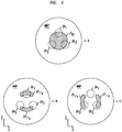
- Figure 1A - 1C illustrate respective first, second, and third embodiments of all-optical amplifiers 10A, 10B, 10C, i.e., rare-earth doped fiber optical amplifiers.
- Each optical amplifier 10A - 10C is configured to receive and amplify light from a set of N corresponding optical propagating modes of an end-coupled input multi-mode optical fiber (MMF) 12.
- the all-optical amplifiers 10A - 10C may be configured to transmit the amplified light to a set of N corresponding optical propagating modes of an end-coupled output MMF 14.
- Each such set of optical propagating modes that couple to the fiber amplifier includes optical propagating modes with nontrivially different lateral light intensity profiles, i.e., profiles differing by more than a scale factor.
- the N optical propagating modes of each such set may carry, in parallel, N or less independent data-modulated optical streams, e.g., one stream per mode and per wavelength band.
- the sets of corresponding optical propagating modes of the input and output MMFs 12, 14 may include the same and/or different optical propagating modes, e.g., LP 01 , LP 11 x, and LP 11 y modes.
- Each of the optical amplifiers 10A - 10C includes a multi-core optical amplifier fiber 16 and first and second optical couplers 18, 20.
- the optical couplers 18, 20 couple the end-faces of the multi-core optical amplifier fiber 16 to the end-faces of the input and/or output MMFs 12, 14 and couple the multi-core optical amplifier fiber 16 to source(s) of forward and/or backwards propagating pump light.
- Some embodiments of the optical amplifiers 10A - 10C may also include forward and/or backwards directed optical pump(s) 22, 24, e.g., laser-light pumps or other suitable pump-light sources for a rare-earth doped optical fiber.
- the multi-core optical amplifier fiber 16 has N optical cores 26 1 - 26 N embedded in an optical cladding matrix 28 as illustrated schematically in Figure 2 .
- the integer N is typically greater than or equal to 3.
- the individual optical cores 26 1 - 26 N may have a higher optical refractive index than the optical cladding material 28 so that the individual optical cores 26 1 - 26 N may guide light there along.
- the optical cores 26 1 - 26 N are distributed in the optical cladding 28 in a fixed or longitudinally varying lateral pattern, e.g., the pattern may rotate around the axis of the multi-core optical amplifier fiber 16.
- the optical cores 26 1 - 26 N may be sufficiently laterally separated so that each individual optical core 26 1 - 26 N has guided mode(s) not substantially overlapping the remaining optical cores 26 1 - 26 N .
- the optical propagating modes may substantially overlap more that one of the N optical cores 26 1 - 26 N .
- individual ones of the optical cores 26 1 - 26 N may be tubular cores.
- the optical refractive index has a higher value in a tubular region centered on the axis of a specific optical core 26 1 - 26 N than in adjacent portions of the optical cladding matrix.
- the optical refractive index has a lower value, e.g., both regions may have optical refractive indexes of the value of the optical cladding matrix.
- the optical refractive index may be constant or may vary with radial distance from the axis of the tubular region.
- the multi-core optical amplifier fiber 16 is doped with one or more types of dopant atoms 28 to support optical amplification in response to optical pumping.
- the dopant atoms 28 may include rare-earth dopant atoms such as erbium, thulium, praseodymium, and/or ytterbium or another conventionally known dopant for producing optical amplification in response to optical pumping.
- the dopant atoms 28 may have various distributions in the multi-core optical fiber 12 in the optical cores 26 1 - 26 N and/or in the optical cladding matrix 26. In various embodiments, such dopant atoms 28 may be concentrated in the optical cores 26 1 - 26 N and/or in optical cladding regions adjacent thereto. Since the intensity of received light is usually larger in and near the optical cores 26 1 - 26 N , such limited distributions of the dopant atoms 28 in the multi-core optical amplifier fiber 16 may provide for more efficient optical amplification.
- the individual optical cores 26 1 - 26 N may be configured and/or located in a lateral pattern in the multi-core optical amplifier fiber 16 to support an efficient end-coupling of the multi-core optical amplifier fiber 16 to a selected set of corresponding optical propagating modes of the MMF(s) 12, 14.
- the end-faces of the N optical cores 26 1 - 26 N may be situated and aligned to be illuminated by non-trivial patterns of the light signals to-be-amplified, which are received from the input MMF 12.
- Each non-trivial pattern typically excites a linear combination of relatively orthogonal optical propagating modes in the multi-core optical amplifier fiber 16, e.g., via a non-trivial pattern of light spots.
- one or more of the end-faces of the N optical cores 26 1 - 26 N may be situated and aligned to be illuminated by a pattern of pump light from the optical pump(s) 22, 24, e.g., a pattern of one or more spots of said pump light.
- the alignment and/or image magnification of such light patterns on the end-face of the multi-core optical amplifier fiber 16 may be selectively set up to reduce optical propagation mode-dependency in the optical gain produced by the optical fiber amplifiers 10A - 10C.
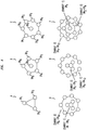
- a configuration of the three-core optical amplifier fiber 16 that may be optically end-coupled to three corresponding propagating optical modes of a few mode optical fiber (FMF) 12 of low optical index contrast is schematically illustrated in Figure 3 .
- the optical cores 26 1 - 26 3 may have about the same diameter and about the same optical refractive indexes and may be about equidistant and symmetrically located about the axis of the three-core optical amplifier fiber 16.
- lateral intensity profiles of approximate optical propagating modes of the FMF 12, i.e., linearly polarized LP 01 , LP 11 y, and LP 11 x modes, are schematically illustrated by cross-hatched regions, and the three optical cores 26 1 - 26 3 are indicated by dashed lines.
- Each cross-hatched region schematically illustrates a high light intensity region of the corresponding one of the LP modes of the FMF 12 at the end-coupled end-face of the three-core optical amplifier fiber 16.
- plates A, B, and C schematically illustrate the high intensity illumination regions on the end-face of the three-core optical amplifier fiber 16 produced by the LP 01 mode, the LP 11 y mode, and the LP 11 x mode, respectively.
- Plates A - C illustrate that the optical coupling of individual LP modes of the three-core FMF 12 to the optical cores 26 1 , 26 2 , 26 3 at the end-face of the multi-core optical amplifier fiber 16 depends on inter-core separations and core-diameters of the optical cores 26 1 - 26 3 .
- some choices for the geometrical parameters defining the three-core optical amplifier fiber 16 may provide a low mode-dependency in the insertion loss with respect to end-coupling of the LP 01 , LP 11 y, and LP 11 x modes of the FMF 12 to the three-core optical amplifier fiber 16.
- each of the three optical cores 26 1 - 26 3 has a core-diameter of about 12.4 micro-meters and a core-to-core separation of about 29.4um and may have a step-index profile with an optical refractive index contrast of about 0.27% with respect to the optical cladding matrix.
- These values of the core-to-core separation and the core-diameter may, e.g., also be scaled by about the same coefficient to smaller values in some other embodiments of the three-core optical amplifier fiber 16.
- a lens system may be used to image light from an output end-face of the FMF 12 onto the input end-face of the three-core optical amplifier fiber 16 with a magnification or a de-magnification that reduces mode-dependent insertion loss.
- Figure 4 illustrates special lateral patterns A, B, C, D, E, F for the N optical cores 26 1 - 26 N of six examples of the multi-core optical amplifier fiber 16 of optical fiber amplifiers 10A - 1C in Figures 1A - 1C .
- the N individual optical cores may have about the same sizes, shapes, and optical refractive indexes.
- the multi-core optical amplifier fiber 16 has 3, 6, 8, 10, 12, and 15 respective optical cores 26 1 - 26 N whose locations are indicated via circular spots.
- Figure 4 also shows imaginary line segments connecting members of disjoint subsets of the N optical cores 26 1 - 26 N of each special lateral pattern A - D.
- the member optical cores 26 1 - 26 N have a simple geometrical relation in the multi-core amplifier optical fiber 16.
- the member optical cores optical cores 26 1 -26 N of an individual subset are located at the vertices of an imaginary and approximately regular polygon with an odd number of vertices, i.e., a polygon as indicated by the line segments.
- a single vertex object is considered a degenerate polygon.
- the special lateral patterns B - F have a plurality of such polygons, which are typically about concentric and may be, e.g., centered on an axis of the multi-core optical amplifier fiber 16.
- the special lateral patterns B - F there are two or more disjoint subsets of formed by the N optical cores optical cores 26 1 - 26 N .
- a first of the subsets is centrally located in the multi-core optical amplifier fiber 16, and one or more other subsets, wherein each such other subset is formed by an odd number of equally spaced optical cores that are arranged along a circle and surround the first subset.
- other lateral patterns of the N optical cores 26 1 - 26 N wherein the number N is larger, may also have such special forms.
- Such special lateral patterns of the N optical cores 26 1 - 26 N are believed by the applicants to provide advantageous properties to the optical amplifiers 10A - 10C of Figures 1A - 1C .
- the N optical cores 26 1 - 26 N of the multi-core optical doped-amplifier fiber 16 are arranged in such special lateral patterns, the applicants believe that end-coupling the multi-core optical doped-amplifier fiber 16 to the input and/or output MMFs 12, 14 may, e.g., be possible with a low optical-propagation-mode dependency in the resulting gain of the optical fiber amplifier 10A - 10C.
- the special lateral patterns A, B, C, D, E, and F are believed to be advantageous for end-coupling the multi-core optical doped-amplifier fiber 16 to the following respective sets of LP optical propagating modes:
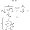
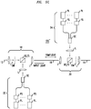
- Figures 5A , 5B , and 5C illustrate specific embodiments 10A', 10B', and 10C' of the respective all-optical amplifiers 10A, 10B, and 10C of Figures 1A, 1B, and 1C .
- the all-optical amplifiers 10A'-10C' include special embodiments of the first and second optical couplers 18, 20 and one or both of the pump light source(s) 22, 24 as shown in Figures 1A - 1C .
- the first and second optical couplers 18, 20 may optionally include one or more lens systems (L) that function to collimate and/or image light received from the MMF(s) 12, 14, multi-core optical amplifier fiber 16, and/or the pump light sources 22, 24. Such imaging may more efficiently align illumination beams of light from the input MMF 12 and/or pump light from the pump source(s) with the optical cores 26 1 - 26 N of the multi-core optical amplifier fiber 16.
- L lens systems
- one or more of the first and second optical couplers 18, 20 may optionally include an optical mask (OM) that is configured to equalize the overall gain of the optical fiber amplifier 10A' - 10C'.
- optical mask(s) OM may provide spatially varying phase and/or amplitude filtering of an incident light beam.
- the filtering may be configured to attenuate incident light in a manner that depends nontrivially on the light's optical propagating mode in the input or output multi-mode optical fiber 12, 14 whose end-face is adjacent to the optical mask OM.
- This mode-dependent attenuation may be produced in the optical mask OM itself or may be produced at or in one of the optical fibers 16, 14 receiving light processed by the optical mask OM, e.g., due to destructive optical interference.
- the optional optical mask(s) OM may include one or more wavelength-dependent filters.
- the spectral dependency of such a filter may be used to provide spectral gain flattening.
- optical couplers 18, 20 may also include an optical isolator.
- optical isolator(s) may be located in the optical free space path between the input and/or output MMF(s) 12, 14 and a dichroic combiner or splitter (DC/S) of the adjacent optical coupler 18, 20, and/or an optical isolator may be located in the optical free space path between the input or output MMF 12, 14 and the nearby end of the multi-core optical amplifier fiber 16.
- some of the first and second optical couplers 18, 20 may include a 2x1 all-optical coupler configured to receive light output by a nearby one of the optical pumps 22, 24 and light output by a nearby end-face of the input MMF 12 or the multi-core optical amplifier fiber 16.
- a 2x1 optical coupler may be a conventionally known 2x1 optical coupler, e.g., a 2x1 optical power coupler (OC) or a dichroic optical combiner or separator (DC/S).
- the forward and/or backward directed pump light source(s) 22, 24 may include a polarization scrambler(s) and pump laser(s).
- polarization scrambler(s) PS may randomize the polarization of light received from the corresponding pump laser(s) PL so that pump light more efficiently excites rare-earth dopant atoms in the multi-core optical amplifier fiber 16, e.g., to reduce polarization dependencies.
- Such a polarization scrambler PS may, e.g., combine light emitted at different times by the corresponding pump laser PL , e.g., light emitted at times separated by more than the temporal coherence time of said pump laser.
- the forward and/or backward directed pump light source(s) 22, 24 may include multiple laser sources whose output light beams are spatially combined by an optical coupler (OC), e.g., a fiber bundle, to form a pump light beam with a nontrivial cross section.
- the pump light beams may be combined so that the nearby optical coupler 18, 20 forms a special spot pattern of pump light on the nearby end-face of the multi-core optical amplifier fiber 16.
- Such a special spot pattern may be configured so that the pump light preferentially illuminates the end-faces of one, more than one, or all of N optical cores of the multi-core optical amplifier fiber 16.
- Such a spatial distribution of pump illumination on the end-face of the multi-core optical amplifier fiber 16 via may increase pumping efficiency in embodiments in which rare-earth dopant atoms are preferentially distributed in and/or adjacent to the optical cores 26 1 - 26 N therein. In some such embodiments, it may be unnecessary to illuminate the end-faces of all N of the optical cores 26 1 - 26 N , because, the optical cores 26 1 - 26 N the multi-core optical amplifier fiber 16 are substantially optically coupled.
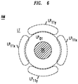
- Figure 6 illustrates an example of an optical attenuator mask (AM) useable to optically mode-equalize in embodiments of the all-optical amplifiers 10A' - 10C; of Figures 5A -5C in which light of LP 01 , LP 11 x, and LP 11 x optical propagating modes is amplified.
- the optical attenuator mask has two disjoint regions, i.e., a DK region and an LT region.
- the DK region is a disk-like region indicated by cross-hatching
- the LT region is the remainder of the face of the optical attenuator mask AM.
- dashed regions indicate areas where the respective LP 01 , LP 11 x, and LP 11 x optical propagating modes have substantial light intensities on the input face of the optical attenuator AM.
- the regions of substantial light intensities overlap the DK and LT regions of the optical attenuator mask AM very differently.
- only the LP 01 optical propagating mode has a substantial overlap with the DK region.
- the optical attenuator mask AM is a spatially varying amplitude mask for which the DK region provides strong optical attenuation and the LT region provides a relatively much weaker optical attenuation. Since only the LP 01 optical propagating mode has a substantial light intensity on the DK region, this example of the optical attenuator mask will provide a mode equalization in which the intensity of the LP 01 optical propagating mode is attenuated with respect to that of the two LP 11 optical propagating modes.
- the optical attenuator mask AM is a spatially varying phase mask for which the DK region and the LT region provide phase modulations that differ by a relative phase of about 180 degrees. Since only the LP 01 optical propagating mode has a substantial intensity on the DK region, this example of the optical attenuator mask will again provide a mode equalization in which the intensity of the LP 01 optical propagating mode is attenuated with respect to that of the two LP 11 optical propagating modes. In particular, interference of light of the LP 01 optical propagating mode, which has been transmitted through the optical attenuator mask AM, will be significantly destructive.
- such interference may occur in the multi-core optical amplifier fiber 16 or in the output MMF 14 of Figures 5A - 5C , e.g., depending on the location of the optical attenuator mask AM.
- such interference should not significantly attenuate light of the LP 11 optical propagating modes, because such light only substantially passes through the LT region of the optical attenuator mask AM.
- Figure 7 illustrates an all-optical communication system 2 having (M+1) spans S1, S2, ..., S(M+1) of transmission MMF; one or more all-optical end-connectors 10 1 , 10 2 , ... 10 M ; an optical data transmitter 4, which converts electrical data stream(s) to optical data streams(s); and an optical data receiver 6, which converts optical data stream(s) to electrical data streams(s).
- the integer M may be 1 or may be greater than 1.
- the spans S1 - S(M+1) may be, e.g., spans of the same type of MMF, e.g., MMFs propagating approximately the same set of optical propagating modes.
- the spans SP1 - SP(M+1) are end-connected together to form an all-optical fiber transmission line between the optical data transmitter 4 and receiver 6 via all-optical end-connectors 10 1 , 10 2 , ... 10 M .
- One or more of the optical end connectors 10 1 -10 M include all-optical fiber amplifier(s) 10A - 10C as illustrated in Figures 1A - 1C and 2.
- said all-optical amplifiers may end-connect to the end-faces of the pair of adjacent spans of MMF.
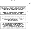
- Figure 8 schematically illustrates a method 30 for operating an all-optical fiber amplifier to amplify one or more parallel streams of optical signal being carried by multiple optical propagating modes of multi-mode optical fiber(s).
- the 30 method may be used to operate any of the all-optical amplifier(s) 10A - 10C, 10A' - 10C' of Figures1A - 1C , 2, and 5A - 5C .
- the method 30 includes, at an end-face of a rare-earth doped, multi-core optical fiber, e.g., the multi-core optical amplifier fiber 16 of Figures 1A - 1C , receiving the one or more streams of optical signals from an end-face of a multi-mode optical fiber, e.g., the input MMF 12 of Figures 1A - 1C and 5A - 5C (step 32).
- the one or more streams typically include optical data modulated carrier(s) that are carried via a set of optical propagation modes of the recited multimode optical fiber.
- the set of optical propagation modes may carry optical signals in one wavelength band or may carry optical signals in a sequence of non-overlapping wavelength bands, .e.g., to implement wavelength division multiplexing.
- the different optical propagation modes of the set have optical intensity and/or phase cross-sectional profiles, which are non-trivially different.
- the set includes optical propagating modes that are relatively orthogonal modes of the MMF.
- Some of the optical propagating modes of the set have non-trivially different lateral intensity profiles, i.e., differing by more than a scale transformation, and/or different angular momentum eigenvalues.
- the method 30 includes amplifying the received one or more streams of optical signals in the rare-earth-doped, multi-core optical fiber (step 34).
- the amplifying includes optically pumping the multi-core optical fiber with one or more pump light sources, e.g., the forward pumping light source 22 and/or the backwards pumping light source 24 of Figures 1A - 1C and 5A - 5C .
- the method 30 may further include, from an end-face of the rare-earth doped, multi-core optical amplifier fiber, transmitting the amplified one or more streams of optical signals to an end-face of a second multi-mode optical fiber, e.g., the MMF 14 of Figures 1A - 1C and 5A - 5C (step 36).
- the transmitting may occur from a different second end-face of the multi-core optical amplifier fiber, e.g., as illustrated in Figures 1A - 1C and 5A - 5C .
- the transmitting may occur from the same input end-face of the rare-earth doped, multi-core optical amplifier fiber that received light of the one or more streams in the step 32, i.e., a configuration not shown in Figures 1A - 1C .
- the second end-face of the rare-earth doped, multi-core optical amplifier fiber may be oriented to face a nearby mirror, which sends amplified light back into the same rare-earth doped, multi-core optical amplifier fiber.
- The, such amplified light may be further amplified and finally extracted from the original input end-face of said same multi-core optical amplifier fiber by an optical circulator, which sends said amplified light to the end-face of an output multi-mode optical fiber of the step 36.
- the method 30 may also include, at an end-face of a second rare-earth doped multi-core optical fiber, receiving the one or more streams of optical signals via the second multi-mode optical fiber in response to the transmitting and amplifying the received one or more streams of optical signals in the second rare-earth-doped, multi-core optical amplifier fiber (step 38).
- the second rare-earth doped, multi-core optical fiber, which is acting in the step 38 may be located in a different all-optical end connector 101 - 10M of Figure 7 than the first rare-earth doped, multi-core optical fiber, which is acting in the steps 32 - 34.
- the method may further include optically attenuating light being communicated between the rare-earth dopes multi-core optical fiber(s) and one of the multi-mode optical fibers in a manner that nontrivially adjusts intensity based on an optical propagating mode of the light in the one of the multi-mode optical fibers.
- optical propagation modes of various embodiments have been described with respect to data communications on a single wavelength band, e.g., supporting data-modulated optical carriers on a set of optical propagation modes of transmission span(s) of MMF.
- These embodiments include are meant to include examples where a sequence of overlapping wavelength bands support data-modulated optical carriers, e.g., via wavelength division multiplexing (WDM).
- WDM wavelength division multiplexing
- one or more optical propagation modes of the set of optical propagation modes may carry separate data-modulated optical carriers on the non-overlapping wavelength bands of the sequence.
- optical amplifiers and the optical communication systems with optical amplifier(s), which are described herein may include additional conventional optical components.
- the additional conventional optical components may include, e.g., optical isolator(s) and/or optical gain flattening filter(s), which remove or alter wavelength dependencies of transmission properties.
- These additional optical components may be placed in the embodiments of optical amplifiers and/or the embodiments of all-optical transmission lines in manners that would be easily understood by persons of ordinary skill in the art in light of teachings of this application.
- Such conventional optical components may be deployed in a manner similar to the deployment of such optical components in optical amplifiers and/or all-optical transmission lines based on single-mode optical fiber.
Landscapes
- Physics & Mathematics (AREA)
- Electromagnetism (AREA)
- Engineering & Computer Science (AREA)
- Plasma & Fusion (AREA)
- Optics & Photonics (AREA)
- Lasers (AREA)
- Optical Communication System (AREA)
- Optical Couplings Of Light Guides (AREA)
Applications Claiming Priority (3)
| Application Number | Priority Date | Filing Date | Title |
|---|---|---|---|
| US201261692735P | 2012-08-24 | 2012-08-24 | |
| US13/632,038 US8867125B2 (en) | 2012-08-24 | 2012-09-30 | Multi-mode optical fiber amplifier |
| PCT/US2013/052490 WO2014031289A1 (en) | 2012-08-24 | 2013-07-29 | Multi-core optical fiber amplifier and its coupling with multimode fibers |
Publications (2)
| Publication Number | Publication Date |
|---|---|
| EP2888618A1 EP2888618A1 (en) | 2015-07-01 |
| EP2888618B1 true EP2888618B1 (en) | 2017-06-07 |
Family
ID=50147772
Family Applications (1)
| Application Number | Title | Priority Date | Filing Date |
|---|---|---|---|
| EP13748407.7A Active EP2888618B1 (en) | 2012-08-24 | 2013-07-29 | Multi-core optical fiber amplifier and its coupling with multimode fibers |
Country Status (6)
| Country | Link |
|---|---|
| US (1) | US8867125B2 (zh) |
| EP (1) | EP2888618B1 (zh) |
| JP (1) | JP6109940B2 (zh) |
| KR (1) | KR20150038197A (zh) |
| CN (1) | CN104583823B (zh) |
| WO (1) | WO2014031289A1 (zh) |
Families Citing this family (16)
| Publication number | Priority date | Publication date | Assignee | Title |
|---|---|---|---|---|
| EP2693672A1 (en) * | 2012-07-30 | 2014-02-05 | Xieon Networks S.à.r.l. | Optical network and optical network element |
| US9778418B2 (en) | 2012-09-15 | 2017-10-03 | Alcatel Lucent | Multi-mode optical transmission line with differential modal group delay compensation |
| US9362708B2 (en) * | 2013-09-20 | 2016-06-07 | Alcatel Lucent | Compact two-stage optical amplifier |
| US20150085352A1 (en) * | 2013-09-20 | 2015-03-26 | Alcatel-Lucent Usa Inc. | Optical amplifier for space-division multiplexing |
| JP5957718B2 (ja) * | 2014-04-24 | 2016-07-27 | 国立研究開発法人情報通信研究機構 | マルチコア・マルチモードファイバ結合装置 |
| JP6517946B2 (ja) * | 2015-11-26 | 2019-05-22 | 日本電信電話株式会社 | 光増幅システム及び光増幅方法 |
| EP3273623B1 (en) * | 2016-07-18 | 2024-09-18 | Institut Mines Telecom | Optical fiber transmission link with multimode optical fiber and scrambler |
| WO2018075111A2 (en) * | 2016-07-20 | 2018-04-26 | University Of Rochester | Lma fibers for suppression of thermal mode instability |
| CN106100741B (zh) * | 2016-08-22 | 2018-09-11 | 北京邮电大学 | 一种信号均衡方法及装置 |
| CN109952686B (zh) * | 2016-11-01 | 2021-01-12 | 日本电信电话株式会社 | 光放大器 |
| EP3562065A1 (en) * | 2018-04-27 | 2019-10-30 | Institut Mines-Telecom | Methods and devices for the determination of core dependent loss in multi-core fiber transmission systems using core scrambling |
| JP2020013031A (ja) * | 2018-07-19 | 2020-01-23 | 日本電信電話株式会社 | モード等化フィルタ |
| US20210399514A1 (en) * | 2018-10-01 | 2021-12-23 | Nec Corporation | Optical amplification apparatus and optical amplification method |
| DE102020127432A1 (de) | 2020-10-19 | 2022-04-21 | Fraunhofer-Gesellschaft zur Förderung der angewandten Forschung eingetragener Verein | Gepulster oder kontinuierlicher Faserlaser oder -verstärker mit speziell dotierter aktiver Faser |
| US20240266796A1 (en) * | 2021-06-23 | 2024-08-08 | B.G. Negev Technologies And Applications Ltd. | Super-mode selective optical unit |
| CN113872034B (zh) * | 2021-12-02 | 2022-05-06 | 武汉锐科光纤激光技术股份有限公司 | 光束的生成设备、方法和装置、存储介质及电子装置 |
Family Cites Families (10)
| Publication number | Priority date | Publication date | Assignee | Title |
|---|---|---|---|---|
| US6175435B1 (en) * | 1995-11-22 | 2001-01-16 | Fujitsu Limited | Optical communication system using optical phase conjugation to suppress waveform distortion caused by chromatic dispersion and optical kerr effect |
| CA2182830C (en) | 1996-02-22 | 2002-06-18 | Katsuyuki Imoto | Rare earth element-doped multiple-core optical fiber and optical systems using the same |
| US8355638B2 (en) * | 2009-06-26 | 2013-01-15 | Alcatel Lucent | Receiver for optical transverse-mode-multiplexed signals |
| EP2446560A1 (en) * | 2009-06-26 | 2012-05-02 | Alcatel Lucent | Receiver for optical transverse-mode-multiplexed signals |
| US9563011B2 (en) | 2010-01-27 | 2017-02-07 | University Of Central Florida Research Foundation, Inc. | Optical transmission using few-mode fibers |
| JP5570460B2 (ja) | 2010-03-10 | 2014-08-13 | オーエフエス ファイテル,エルエルシー | 多芯ファイバ伝送システムおよび多芯ファイバ伝送方法 |
| JP5643418B2 (ja) * | 2010-03-16 | 2014-12-17 | オーエフエス ファイテル,エルエルシー | 伝送、および増幅用マルチコアファイバ、および増幅器コアにポンプ光を発射するための仕組み |
| US8538275B2 (en) * | 2010-04-05 | 2013-09-17 | Alcatel Lucent | Multimode optical communication |
| SG184461A1 (en) * | 2010-04-05 | 2012-11-29 | Alcatel Lucent | Multimode optical communication |
| US8503845B2 (en) * | 2011-01-17 | 2013-08-06 | Alcatel Lucent | Multi-core optical fiber and optical communication systems |
-
2012
- 2012-09-30 US US13/632,038 patent/US8867125B2/en active Active
-
2013
- 2013-07-29 CN CN201380044137.0A patent/CN104583823B/zh active Active
- 2013-07-29 WO PCT/US2013/052490 patent/WO2014031289A1/en active Application Filing
- 2013-07-29 EP EP13748407.7A patent/EP2888618B1/en active Active
- 2013-07-29 KR KR1020157004447A patent/KR20150038197A/ko not_active Application Discontinuation
- 2013-07-29 JP JP2015528493A patent/JP6109940B2/ja active Active
Also Published As
| Publication number | Publication date |
|---|---|
| CN104583823A (zh) | 2015-04-29 |
| JP2015530744A (ja) | 2015-10-15 |
| CN104583823B (zh) | 2018-09-25 |
| JP6109940B2 (ja) | 2017-04-05 |
| US8867125B2 (en) | 2014-10-21 |
| US20140055843A1 (en) | 2014-02-27 |
| WO2014031289A1 (en) | 2014-02-27 |
| EP2888618A1 (en) | 2015-07-01 |
| KR20150038197A (ko) | 2015-04-08 |
Similar Documents
| Publication | Publication Date | Title |
|---|---|---|
| EP2888618B1 (en) | Multi-core optical fiber amplifier and its coupling with multimode fibers | |
| US8767288B2 (en) | Multimode optical amplifier with close-loop modal gain control | |
| JP5862131B2 (ja) | 光増幅装置 | |
| JP5416314B2 (ja) | マルチコア増幅光ファイバおよびマルチコア光ファイバ増幅器 | |
| EP2742377B1 (en) | Few moded fiber device employing mode conversion | |
| Yung et al. | First demonstration of multimode amplifier for spatial division multiplexed transmission systems | |
| JP6348535B2 (ja) | ハイパワー・ダブルクラッド(dc)・ポンプ・エルビウム・ドープ・ファイバ増幅器(edfa) | |
| Ono et al. | 12-core double-clad Er/Yb-doped fiber amplifier employing free-space coupling pump/signal combiner module | |
| Sakaguchi et al. | Propagation characteristics of seven-core fiber for spatial and wavelength division multiplexed 10-Gbit/s channels | |
| US8638493B2 (en) | Optical system for signal amplification using a multimode fiber | |
| JP2014236210A (ja) | マルチコア光伝送システム、光増幅及び光増幅用部品 | |
| US11888281B2 (en) | Multimode optical amplifier | |
| CN102130416B (zh) | 激光装置 | |
| Jung et al. | High spatial density 6-mode 7-core multicore L-band fiber amplifier | |
| CN109952686B (zh) | 光放大器 | |
| Wada et al. | Coupled 2-LP 6-core EDFA with 125 μm cladding diameter | |
| Du et al. | FIFO-less Core-pumped Multicore Erbium-doped Fiber Amplifier with Hybrid Passive Components | |
| Tsuchida | Multicore EDFA | |
| Jiang et al. | Experiments and simulation on the overall DMG of long-haul cascade FM-EDFA systems | |
| Rancaño et al. | Multi-element fiber technology for high-capacity optical communication systems | |
| Liu et al. | Pump Mode Characterization of Annular Cladding Erbium-Doped Fibers Using Low-Coherence Interferometry | |
| Wakayama et al. | High-capacity Few-mode Multicore Fiber Transmission | |
| Chen | Passive and active building blocks for space-division-multiplexed optical networks | |
| Nakatani et al. | Proposal of center core pumped multi-core erbium-doped fibers |
Legal Events
| Date | Code | Title | Description |
|---|---|---|---|
| PUAI | Public reference made under article 153(3) epc to a published international application that has entered the european phase |
Free format text: ORIGINAL CODE: 0009012 |
|
| 17P | Request for examination filed |
Effective date: 20150324 |
|
| AK | Designated contracting states |
Kind code of ref document: A1 Designated state(s): AL AT BE BG CH CY CZ DE DK EE ES FI FR GB GR HR HU IE IS IT LI LT LU LV MC MK MT NL NO PL PT RO RS SE SI SK SM TR |
|
| AX | Request for extension of the european patent |
Extension state: BA ME |
|
| DAX | Request for extension of the european patent (deleted) | ||
| GRAP | Despatch of communication of intention to grant a patent |
Free format text: ORIGINAL CODE: EPIDOSNIGR1 |
|
| INTG | Intention to grant announced |
Effective date: 20170113 |
|
| GRAS | Grant fee paid |
Free format text: ORIGINAL CODE: EPIDOSNIGR3 |
|
| AK | Designated contracting states |
Kind code of ref document: B1 Designated state(s): AL AT BE BG CH CY CZ DE DK EE ES FI FR GB GR HR HU IE IS IT LI LT LU LV MC MK MT NL NO PL PT RO RS SE SI SK SM TR |
|
| REG | Reference to a national code |
Ref country code: GB Ref legal event code: FG4D |
|
| GRAA | (expected) grant |
Free format text: ORIGINAL CODE: 0009210 |
|
| REG | Reference to a national code |
Ref country code: CH Ref legal event code: EP Ref country code: AT Ref legal event code: REF Ref document number: 899649 Country of ref document: AT Kind code of ref document: T Effective date: 20170615 |
|
| REG | Reference to a national code |
Ref country code: IE Ref legal event code: FG4D |
|
| REG | Reference to a national code |
Ref country code: DE Ref legal event code: R096 Ref document number: 602013021997 Country of ref document: DE |
|
| REG | Reference to a national code |
Ref country code: FR Ref legal event code: PLFP Year of fee payment: 5 |
|
| REG | Reference to a national code |
Ref country code: NL Ref legal event code: MP Effective date: 20170607 |
|
| REG | Reference to a national code |
Ref country code: LT Ref legal event code: MG4D |
|
| PG25 | Lapsed in a contracting state [announced via postgrant information from national office to epo] |
Ref country code: HR Free format text: LAPSE BECAUSE OF FAILURE TO SUBMIT A TRANSLATION OF THE DESCRIPTION OR TO PAY THE FEE WITHIN THE PRESCRIBED TIME-LIMIT Effective date: 20170607 Ref country code: LT Free format text: LAPSE BECAUSE OF FAILURE TO SUBMIT A TRANSLATION OF THE DESCRIPTION OR TO PAY THE FEE WITHIN THE PRESCRIBED TIME-LIMIT Effective date: 20170607 Ref country code: FI Free format text: LAPSE BECAUSE OF FAILURE TO SUBMIT A TRANSLATION OF THE DESCRIPTION OR TO PAY THE FEE WITHIN THE PRESCRIBED TIME-LIMIT Effective date: 20170607 Ref country code: ES Free format text: LAPSE BECAUSE OF FAILURE TO SUBMIT A TRANSLATION OF THE DESCRIPTION OR TO PAY THE FEE WITHIN THE PRESCRIBED TIME-LIMIT Effective date: 20170607 Ref country code: NO Free format text: LAPSE BECAUSE OF FAILURE TO SUBMIT A TRANSLATION OF THE DESCRIPTION OR TO PAY THE FEE WITHIN THE PRESCRIBED TIME-LIMIT Effective date: 20170907 Ref country code: GR Free format text: LAPSE BECAUSE OF FAILURE TO SUBMIT A TRANSLATION OF THE DESCRIPTION OR TO PAY THE FEE WITHIN THE PRESCRIBED TIME-LIMIT Effective date: 20170908 |
|
| REG | Reference to a national code |
Ref country code: AT Ref legal event code: MK05 Ref document number: 899649 Country of ref document: AT Kind code of ref document: T Effective date: 20170607 |
|
| PG25 | Lapsed in a contracting state [announced via postgrant information from national office to epo] |
Ref country code: NL Free format text: LAPSE BECAUSE OF FAILURE TO SUBMIT A TRANSLATION OF THE DESCRIPTION OR TO PAY THE FEE WITHIN THE PRESCRIBED TIME-LIMIT Effective date: 20170607 Ref country code: SE Free format text: LAPSE BECAUSE OF FAILURE TO SUBMIT A TRANSLATION OF THE DESCRIPTION OR TO PAY THE FEE WITHIN THE PRESCRIBED TIME-LIMIT Effective date: 20170607 Ref country code: RS Free format text: LAPSE BECAUSE OF FAILURE TO SUBMIT A TRANSLATION OF THE DESCRIPTION OR TO PAY THE FEE WITHIN THE PRESCRIBED TIME-LIMIT Effective date: 20170607 Ref country code: LV Free format text: LAPSE BECAUSE OF FAILURE TO SUBMIT A TRANSLATION OF THE DESCRIPTION OR TO PAY THE FEE WITHIN THE PRESCRIBED TIME-LIMIT Effective date: 20170607 Ref country code: BG Free format text: LAPSE BECAUSE OF FAILURE TO SUBMIT A TRANSLATION OF THE DESCRIPTION OR TO PAY THE FEE WITHIN THE PRESCRIBED TIME-LIMIT Effective date: 20170907 |
|
| PG25 | Lapsed in a contracting state [announced via postgrant information from national office to epo] |
Ref country code: AT Free format text: LAPSE BECAUSE OF FAILURE TO SUBMIT A TRANSLATION OF THE DESCRIPTION OR TO PAY THE FEE WITHIN THE PRESCRIBED TIME-LIMIT Effective date: 20170607 Ref country code: EE Free format text: LAPSE BECAUSE OF FAILURE TO SUBMIT A TRANSLATION OF THE DESCRIPTION OR TO PAY THE FEE WITHIN THE PRESCRIBED TIME-LIMIT Effective date: 20170607 Ref country code: RO Free format text: LAPSE BECAUSE OF FAILURE TO SUBMIT A TRANSLATION OF THE DESCRIPTION OR TO PAY THE FEE WITHIN THE PRESCRIBED TIME-LIMIT Effective date: 20170607 Ref country code: CZ Free format text: LAPSE BECAUSE OF FAILURE TO SUBMIT A TRANSLATION OF THE DESCRIPTION OR TO PAY THE FEE WITHIN THE PRESCRIBED TIME-LIMIT Effective date: 20170607 Ref country code: SK Free format text: LAPSE BECAUSE OF FAILURE TO SUBMIT A TRANSLATION OF THE DESCRIPTION OR TO PAY THE FEE WITHIN THE PRESCRIBED TIME-LIMIT Effective date: 20170607 |
|
| PG25 | Lapsed in a contracting state [announced via postgrant information from national office to epo] |
Ref country code: PL Free format text: LAPSE BECAUSE OF FAILURE TO SUBMIT A TRANSLATION OF THE DESCRIPTION OR TO PAY THE FEE WITHIN THE PRESCRIBED TIME-LIMIT Effective date: 20170607 Ref country code: IS Free format text: LAPSE BECAUSE OF FAILURE TO SUBMIT A TRANSLATION OF THE DESCRIPTION OR TO PAY THE FEE WITHIN THE PRESCRIBED TIME-LIMIT Effective date: 20171007 Ref country code: SM Free format text: LAPSE BECAUSE OF FAILURE TO SUBMIT A TRANSLATION OF THE DESCRIPTION OR TO PAY THE FEE WITHIN THE PRESCRIBED TIME-LIMIT Effective date: 20170607 Ref country code: IT Free format text: LAPSE BECAUSE OF FAILURE TO SUBMIT A TRANSLATION OF THE DESCRIPTION OR TO PAY THE FEE WITHIN THE PRESCRIBED TIME-LIMIT Effective date: 20170607 |
|
| REG | Reference to a national code |
Ref country code: CH Ref legal event code: PL |
|
| REG | Reference to a national code |
Ref country code: DE Ref legal event code: R097 Ref document number: 602013021997 Country of ref document: DE |
|
| PG25 | Lapsed in a contracting state [announced via postgrant information from national office to epo] |
Ref country code: MC Free format text: LAPSE BECAUSE OF FAILURE TO SUBMIT A TRANSLATION OF THE DESCRIPTION OR TO PAY THE FEE WITHIN THE PRESCRIBED TIME-LIMIT Effective date: 20170607 |
|
| PLBE | No opposition filed within time limit |
Free format text: ORIGINAL CODE: 0009261 |
|
| STAA | Information on the status of an ep patent application or granted ep patent |
Free format text: STATUS: NO OPPOSITION FILED WITHIN TIME LIMIT |
|
| RAP2 | Party data changed (patent owner data changed or rights of a patent transferred) |
Owner name: ALCATEL LUCENT |
|
| PG25 | Lapsed in a contracting state [announced via postgrant information from national office to epo] |
Ref country code: LI Free format text: LAPSE BECAUSE OF NON-PAYMENT OF DUE FEES Effective date: 20170731 Ref country code: CH Free format text: LAPSE BECAUSE OF NON-PAYMENT OF DUE FEES Effective date: 20170731 Ref country code: DK Free format text: LAPSE BECAUSE OF FAILURE TO SUBMIT A TRANSLATION OF THE DESCRIPTION OR TO PAY THE FEE WITHIN THE PRESCRIBED TIME-LIMIT Effective date: 20170607 |
|
| REG | Reference to a national code |
Ref country code: IE Ref legal event code: MM4A |
|
| 26N | No opposition filed |
Effective date: 20180308 |
|
| PG25 | Lapsed in a contracting state [announced via postgrant information from national office to epo] |
Ref country code: SI Free format text: LAPSE BECAUSE OF FAILURE TO SUBMIT A TRANSLATION OF THE DESCRIPTION OR TO PAY THE FEE WITHIN THE PRESCRIBED TIME-LIMIT Effective date: 20170607 |
|
| REG | Reference to a national code |
Ref country code: BE Ref legal event code: MM Effective date: 20170731 |
|
| PG25 | Lapsed in a contracting state [announced via postgrant information from national office to epo] |
Ref country code: LU Free format text: LAPSE BECAUSE OF NON-PAYMENT OF DUE FEES Effective date: 20170729 |
|
| REG | Reference to a national code |
Ref country code: FR Ref legal event code: PLFP Year of fee payment: 6 |
|
| PG25 | Lapsed in a contracting state [announced via postgrant information from national office to epo] |
Ref country code: IE Free format text: LAPSE BECAUSE OF NON-PAYMENT OF DUE FEES Effective date: 20170729 |
|
| PG25 | Lapsed in a contracting state [announced via postgrant information from national office to epo] |
Ref country code: BE Free format text: LAPSE BECAUSE OF NON-PAYMENT OF DUE FEES Effective date: 20170731 |
|
| PG25 | Lapsed in a contracting state [announced via postgrant information from national office to epo] |
Ref country code: MT Free format text: LAPSE BECAUSE OF NON-PAYMENT OF DUE FEES Effective date: 20170729 |
|
| PG25 | Lapsed in a contracting state [announced via postgrant information from national office to epo] |
Ref country code: HU Free format text: LAPSE BECAUSE OF FAILURE TO SUBMIT A TRANSLATION OF THE DESCRIPTION OR TO PAY THE FEE WITHIN THE PRESCRIBED TIME-LIMIT; INVALID AB INITIO Effective date: 20130729 |
|
| PG25 | Lapsed in a contracting state [announced via postgrant information from national office to epo] |
Ref country code: CY Free format text: LAPSE BECAUSE OF FAILURE TO SUBMIT A TRANSLATION OF THE DESCRIPTION OR TO PAY THE FEE WITHIN THE PRESCRIBED TIME-LIMIT Effective date: 20170607 |
|
| PG25 | Lapsed in a contracting state [announced via postgrant information from national office to epo] |
Ref country code: MK Free format text: LAPSE BECAUSE OF FAILURE TO SUBMIT A TRANSLATION OF THE DESCRIPTION OR TO PAY THE FEE WITHIN THE PRESCRIBED TIME-LIMIT Effective date: 20170607 |
|
| PG25 | Lapsed in a contracting state [announced via postgrant information from national office to epo] |
Ref country code: TR Free format text: LAPSE BECAUSE OF FAILURE TO SUBMIT A TRANSLATION OF THE DESCRIPTION OR TO PAY THE FEE WITHIN THE PRESCRIBED TIME-LIMIT Effective date: 20170607 |
|
| PG25 | Lapsed in a contracting state [announced via postgrant information from national office to epo] |
Ref country code: PT Free format text: LAPSE BECAUSE OF FAILURE TO SUBMIT A TRANSLATION OF THE DESCRIPTION OR TO PAY THE FEE WITHIN THE PRESCRIBED TIME-LIMIT Effective date: 20170607 |
|
| PG25 | Lapsed in a contracting state [announced via postgrant information from national office to epo] |
Ref country code: AL Free format text: LAPSE BECAUSE OF FAILURE TO SUBMIT A TRANSLATION OF THE DESCRIPTION OR TO PAY THE FEE WITHIN THE PRESCRIBED TIME-LIMIT Effective date: 20170607 |
|
| PGFP | Annual fee paid to national office [announced via postgrant information from national office to epo] |
Ref country code: DE Payment date: 20230607 Year of fee payment: 11 |
|
| PGFP | Annual fee paid to national office [announced via postgrant information from national office to epo] |
Ref country code: GB Payment date: 20240606 Year of fee payment: 12 |
|
| PGFP | Annual fee paid to national office [announced via postgrant information from national office to epo] |
Ref country code: FR Payment date: 20240611 Year of fee payment: 12 |