EP2886906A1 - Energy absorber for anti-crash seat and an anti-crash seat with such an absorber. - Google Patents
Energy absorber for anti-crash seat and an anti-crash seat with such an absorber. Download PDFInfo
- Publication number
- EP2886906A1 EP2886906A1 EP14196110.2A EP14196110A EP2886906A1 EP 2886906 A1 EP2886906 A1 EP 2886906A1 EP 14196110 A EP14196110 A EP 14196110A EP 2886906 A1 EP2886906 A1 EP 2886906A1
- Authority
- EP
- European Patent Office
- Prior art keywords
- energy absorber
- brake
- shaft
- drum
- rotor
- Prior art date
- Legal status (The legal status is an assumption and is not a legal conclusion. Google has not performed a legal analysis and makes no representation as to the accuracy of the status listed.)
- Granted
Links
- 239000006096 absorbing agent Substances 0.000 title claims abstract description 85
- 230000001133 acceleration Effects 0.000 claims abstract description 53
- 230000001960 triggered effect Effects 0.000 claims description 13
- 230000006835 compression Effects 0.000 claims description 9
- 238000007906 compression Methods 0.000 claims description 9
- 238000004804 winding Methods 0.000 claims description 7
- 230000008859 change Effects 0.000 claims description 3
- 230000000284 resting effect Effects 0.000 claims description 3
- 239000000463 material Substances 0.000 description 6
- 230000008878 coupling Effects 0.000 description 5
- 238000010168 coupling process Methods 0.000 description 5
- 238000005859 coupling reaction Methods 0.000 description 5
- 238000010586 diagram Methods 0.000 description 5
- 230000000670 limiting effect Effects 0.000 description 5
- 238000006073 displacement reaction Methods 0.000 description 4
- 230000000694 effects Effects 0.000 description 4
- 241001417494 Sciaenidae Species 0.000 description 3
- 230000003068 static effect Effects 0.000 description 3
- 229910000831 Steel Inorganic materials 0.000 description 2
- 230000009471 action Effects 0.000 description 2
- 238000010304 firing Methods 0.000 description 2
- 238000000034 method Methods 0.000 description 2
- 239000010959 steel Substances 0.000 description 2
- 230000000295 complement effect Effects 0.000 description 1
- 230000003247 decreasing effect Effects 0.000 description 1
- 230000001066 destructive effect Effects 0.000 description 1
- 230000005489 elastic deformation Effects 0.000 description 1
- 239000000835 fiber Substances 0.000 description 1
- 239000002783 friction material Substances 0.000 description 1
- 230000003100 immobilizing effect Effects 0.000 description 1
- 230000002427 irreversible effect Effects 0.000 description 1
- 230000009347 mechanical transmission Effects 0.000 description 1
- 239000002184 metal Substances 0.000 description 1
- 230000003071 parasitic effect Effects 0.000 description 1
- 230000035515 penetration Effects 0.000 description 1
- 229920005594 polymer fiber Polymers 0.000 description 1
- 239000002861 polymer material Substances 0.000 description 1
- 230000004044 response Effects 0.000 description 1
- 230000000717 retained effect Effects 0.000 description 1
- 230000001052 transient effect Effects 0.000 description 1
Images


Classifications
-
- B—PERFORMING OPERATIONS; TRANSPORTING
- B64—AIRCRAFT; AVIATION; COSMONAUTICS
- B64D—EQUIPMENT FOR FITTING IN OR TO AIRCRAFT; FLIGHT SUITS; PARACHUTES; ARRANGEMENTS OR MOUNTING OF POWER PLANTS OR PROPULSION TRANSMISSIONS IN AIRCRAFT
- B64D11/00—Passenger or crew accommodation; Flight-deck installations not otherwise provided for
- B64D11/06—Arrangements of seats, or adaptations or details specially adapted for aircraft seats
- B64D11/0619—Arrangements of seats, or adaptations or details specially adapted for aircraft seats with energy absorbing means specially adapted for mitigating impact loads for passenger seats, e.g. at a crash
-
- B—PERFORMING OPERATIONS; TRANSPORTING
- B60—VEHICLES IN GENERAL
- B60N—SEATS SPECIALLY ADAPTED FOR VEHICLES; VEHICLE PASSENGER ACCOMMODATION NOT OTHERWISE PROVIDED FOR
- B60N2/00—Seats specially adapted for vehicles; Arrangement or mounting of seats in vehicles
- B60N2/24—Seats specially adapted for vehicles; Arrangement or mounting of seats in vehicles for particular purposes or particular vehicles
- B60N2/42—Seats specially adapted for vehicles; Arrangement or mounting of seats in vehicles for particular purposes or particular vehicles the seat constructed to protect the occupant from the effect of abnormal g-forces, e.g. crash or safety seats
- B60N2/427—Seats or parts thereof displaced during a crash
- B60N2/42727—Seats or parts thereof displaced during a crash involving substantially rigid displacement
- B60N2/42736—Seats or parts thereof displaced during a crash involving substantially rigid displacement of the whole seat
-
- B—PERFORMING OPERATIONS; TRANSPORTING
- B60—VEHICLES IN GENERAL
- B60N—SEATS SPECIALLY ADAPTED FOR VEHICLES; VEHICLE PASSENGER ACCOMMODATION NOT OTHERWISE PROVIDED FOR
- B60N2/00—Seats specially adapted for vehicles; Arrangement or mounting of seats in vehicles
- B60N2/24—Seats specially adapted for vehicles; Arrangement or mounting of seats in vehicles for particular purposes or particular vehicles
- B60N2/42—Seats specially adapted for vehicles; Arrangement or mounting of seats in vehicles for particular purposes or particular vehicles the seat constructed to protect the occupant from the effect of abnormal g-forces, e.g. crash or safety seats
- B60N2/4207—Seats specially adapted for vehicles; Arrangement or mounting of seats in vehicles for particular purposes or particular vehicles the seat constructed to protect the occupant from the effect of abnormal g-forces, e.g. crash or safety seats characterised by the direction of the g-forces
- B60N2/4242—Seats specially adapted for vehicles; Arrangement or mounting of seats in vehicles for particular purposes or particular vehicles the seat constructed to protect the occupant from the effect of abnormal g-forces, e.g. crash or safety seats characterised by the direction of the g-forces vertical
-
- F—MECHANICAL ENGINEERING; LIGHTING; HEATING; WEAPONS; BLASTING
- F16—ENGINEERING ELEMENTS AND UNITS; GENERAL MEASURES FOR PRODUCING AND MAINTAINING EFFECTIVE FUNCTIONING OF MACHINES OR INSTALLATIONS; THERMAL INSULATION IN GENERAL
- F16D—COUPLINGS FOR TRANSMITTING ROTATION; CLUTCHES; BRAKES
- F16D55/00—Brakes with substantially-radial braking surfaces pressed together in axial direction, e.g. disc brakes
- F16D55/02—Brakes with substantially-radial braking surfaces pressed together in axial direction, e.g. disc brakes with axially-movable discs or pads pressed against axially-located rotating members
- F16D55/04—Brakes with substantially-radial braking surfaces pressed together in axial direction, e.g. disc brakes with axially-movable discs or pads pressed against axially-located rotating members by moving discs or pads away from one another against radial walls of drums or cylinders
- F16D55/06—Brakes with substantially-radial braking surfaces pressed together in axial direction, e.g. disc brakes with axially-movable discs or pads pressed against axially-located rotating members by moving discs or pads away from one another against radial walls of drums or cylinders without self-tightening action
- F16D55/08—Mechanically-actuated brakes
-
- F—MECHANICAL ENGINEERING; LIGHTING; HEATING; WEAPONS; BLASTING
- F16—ENGINEERING ELEMENTS AND UNITS; GENERAL MEASURES FOR PRODUCING AND MAINTAINING EFFECTIVE FUNCTIONING OF MACHINES OR INSTALLATIONS; THERMAL INSULATION IN GENERAL
- F16F—SPRINGS; SHOCK-ABSORBERS; MEANS FOR DAMPING VIBRATION
- F16F7/00—Vibration-dampers; Shock-absorbers
- F16F7/02—Vibration-dampers; Shock-absorbers with relatively-rotatable friction surfaces that are pressed together
- F16F7/04—Vibration-dampers; Shock-absorbers with relatively-rotatable friction surfaces that are pressed together in the direction of the axis of rotation
Definitions
- the pulling line comprises for example one or more cable, or one or more straps wound on the drum drum.
- the pulling line comprises for example one or more cable, or one or more straps wound on the drum drum.
- steel cables or polymer fiber straps that can be made with the necessary strength and desired flexibility to be perfectly wound on the drum drum.
- control member 40 comprises a graduated control, for example by mass.
- the axis 12 is parallel to the edges of the elongate faces and passes substantially through the centers of the end faces 103.
Abstract
Un absorbeur d'énergie (100) pour écrêter une force d'accélération subie par un corps pesant, tel qu'un occupant d'un siège soumis à l'accélération d'un crash d'aéronef, comporte un tambour enrouleur (10) monté en rotation autour d'un arbre (13) autour duquel est enroulée une ligne de traction (11). L'arbre est couplé mécaniquement à un frein (20) qui immobilise en rotation l'arbre (13) lorsqu'un couple appliqué à l'arbre par la ligne de traction est inférieur au couple frein maximum pouvant être généré par le frein et qui lorsque l'arbre (13) est en rotation génère un couple sensiblement constant et égal au couple frein maximum. Un organe de contrôle (40) agissant sur le frein (20) permet de modifier la valeur du couple frein maximum et ainsi d'adapter l'absorbeur d'énergie à la masse du corps pesant pour maintenir une accélération subie à une valeur souhaitée pour de masses différentes.An energy absorber (100) for clipping an acceleration force experienced by a heavy body, such as an occupant of a seat subjected to the acceleration of an aircraft crash, comprises a retractor drum (10) rotatably mounted around a shaft (13) around which is wound a traction line (11). The shaft is mechanically coupled to a brake (20) which immobilizes in rotation the shaft (13) when a torque applied to the shaft by the traction line is less than the maximum brake torque that can be generated by the brake and which when the shaft (13) is rotating generates a torque substantially constant and equal to the maximum brake torque. A control member (40) acting on the brake (20) makes it possible to modify the value of the maximum brake torque and thus to adapt the energy absorber to the mass of the heavy body in order to maintain an acceleration undergone at a desired value for different masses.
Description
L'invention appartient au domaine des sièges pour véhicule de transport. Elle concerne plus particulièrement un dispositif pour absorber l'énergie d'un siège en cas de forte accélération et un siège comportant un tel dispositif destiné à être installé dans un véhicule pouvant subir de fortes accélérations.The invention belongs to the field of transport vehicle seats. It relates more particularly to a device for absorbing the energy of a seat in case of strong acceleration and a seat comprising such a device intended to be installed in a vehicle that can undergo strong accelerations.
L'invention trouve en particulier application à bord des aéronefs pour absorber l'énergie en cas d'accélération liée au crash.The invention finds particular application on board aircraft for absorbing energy in case of crash-related acceleration.
Dans le domaine du transport des personnes, en particulier dans le transport aérien, les accélérations provoquées par un crash peuvent atteindre des niveaux difficilement tolérables pour une personne. Il est connu de limiter la valeur de l'accélération maximale subie par une personne à bord d'un aéronef en absorbant une partie de l'énergie appliquée au siège sur lequel se trouve cette personne.In the field of passenger transport, particularly in air transport, acceleration caused by a crash can reach levels that are difficult for a person to tolerate. It is known to limit the value of the maximum acceleration experienced by a person aboard an aircraft by absorbing a portion of the energy applied to the seat on which this person is.
Suivant une méthode connue, par exemple du document
Dans ce cas il est nécessaire de concevoir la structure du siège pour que celle-ci se déforme de manière adaptée et que la structure reste suffisamment résistante pour maintenir le passager. Les règles de conception sont dans ce cas très contraignantes.In this case it is necessary to design the seat structure so that it deforms appropriately and that the structure remains strong enough to maintain the passenger. In this case, the design rules are very restrictive.
Suivant une autre méthode connue, par exemple du document
Ces diverses solutions connues pour limiter les accélérations subies en cas de crash présentent l'inconvénient de conduire à des déformations irréversibles et en conséquence les moyens qui absorbent l'énergie ne peuvent pas être testés unitairement puis remis en état de fonctionnement.These various known solutions for limiting accelerations undergone in the event of a crash have the disadvantage of leading to irreversible deformations and consequently the means that absorb the energy can not be tested individually and then put back into operating condition.
En outre, l'énergie à absorber en cas d'accélération est fonction de la masse du siège avec son occupant. Pour prendre en compte que tous les occupants possibles d'un siège n'ont pas nécessairement le même poids, les dispositifs d'absorption d'énergie sont le plus souvent un compromis entre la masse du passager le plus léger envisagé et celle du plus lourd, ce qui pose des problèmes à la fois sur la valeur maximale de l'accélération subie, plus forte pour l'occupant léger, et sur l'amplitude du mouvement pendant lequel l'accélération est subie, plus grande pour un occupant lourd. Une telle solution ne convient donc que partiellement et imparfaitement dans les cas extrêmes.In addition, the energy to be absorbed in case of acceleration depends on the mass of the seat with its occupant. To take into account that not all the possible occupants of a seat are necessarily the same weight, the energy absorbing devices are most often a compromise between the mass of the lightest passenger envisaged and that of the heaviest. , which poses problems both on the maximum value of the acceleration undergone, stronger for the light occupant, and on the amplitude of the movement during which the acceleration is undergone, greater for a heavy occupant. Such a solution is therefore only partially and imperfectly suited in extreme cases.
Des solutions pour adapter l'absorbeur d'énergie au poids de l'occupant du siège, comme par exemple la solution décrite dans le document
La présente invention a pour objet de remédier à ces inconvénients au moyen un absorbeur d'énergie permettant, pendant une durée de fonctionnement sur une amplitude de déplacement déterminée, de limiter l'accélération à laquelle une masse pesante, telle que le passager d'un siège, est soumise lors d'une forte accélération.The object of the present invention is to overcome these drawbacks by means of an energy absorber enabling, during a period of operation over a determined displacement amplitude, to limit the acceleration at which a heavy mass, such as the passenger of a seat, is subject to strong acceleration.
L'absorbeur d'énergie pour écrêter une force d'accélération subie par un corps pesant comporte un tambour enrouleur monté en rotation autour d'un arbre autour duquel est enroulée, dans une configuration non déclenchée de l'absorbeur d'énergie, une ligne de traction. L'arbre est couplé mécaniquement à un rotor d'un frein à disques dont un stator est immobilisé en rotation par rapport à un boîtier et un élément ressort est monté en compression entre deux sous-ensembles du frein, chaque sous-ensemble comportant des éléments de rotor et de stator montés alternés et mobiles suivant une direction d'un axe de rotation du rotor, de sorte à exercer une force d'appui qui s'applique entre les éléments de rotor et les éléments de stator en contact, afin d'immobiliser en rotation l'arbre lorsqu'un couple appliqué à l'arbre par la ligne de traction soumise à une force de traction est inférieur à un couple frein maximum du frein et qui lorsque l'arbre est en rotation, dans une configuration déclenchée de l'absorbeur d'énergie, génère un couple sensiblement constant et égal au couple frein maximum.The energy absorber for clipping a force of acceleration experienced by a heavy body comprises a winding drum rotatably mounted around a shaft around which is wound, in a non-triggered configuration of the energy absorber, a line traction. The shaft is mechanically coupled to a rotor of a disk brake whose stator is immobilized in rotation with respect to a housing and a spring element is mounted in compression between two subassemblies of the brake, each subassembly comprising elements rotatably mounted and movable rotor and stator in a direction of an axis of rotation of the rotor, so as to exert a bearing force which is applied between the rotor elements and the stator elements in contact, so as to immobilizing in rotation the shaft when a torque applied to the shaft by the traction line subjected to a tractive force is less than a maximum brake torque of the brake and which when the shaft is rotating, in a triggered configuration of the energy absorber generates a substantially constant torque equal to the maximum brake torque.
Il est ainsi obtenu une ligne de traction qui est bloquée lorsque la traction exercée sur la ligne de traction est inférieure à celle produisant sur l'arbre le couple frein maximum du frein et qui est soumise à une force de traction constante lorsque la ligne de traction se déroule du tambour enrouleur.This results in a traction line which is blocked when the traction exerted on the traction line is less than that producing on the shaft the maximum brake torque of the brake and which is subjected to a constant traction force when the traction line unrolling drum.
L'absorbeur d'énergie comporte avantageusement un organe de contrôle agissant sur le frein pour modifier la valeur du couple frein maximum. Il est ainsi possible de modifier la force de traction appliquée par la ligne de traction lorsque la ligne de traction se déroule et d'adapter cette force de traction à une masse pesante fixée à l'extrémité libre de la ligne de traction pour obtenir une accélération subie par la masse pesante sensiblement indépendante de la valeur de la masse considérée.The energy absorber advantageously comprises a control member acting on the brake to change the value of the maximum brake torque. It is thus possible to modify the traction force applied by the traction line when the traction line is unwound and to adapt this traction force to a heavy mass fixed at the free end of the traction line to obtain acceleration. suffered by the heavy mass substantially independent of the value of the mass considered.
Suivant les configurations techniquement possibles, l'absorbeur d'énergie comporte toute ou partie des caractéristiques suivantes.According to the technically possible configurations, the energy absorber comprises all or some of the following characteristics.
Dans une forme de réalisation le frein de l'absorbeur d'énergie comporte un rotor couplé en rotation à l'arbre du tambour enrouleur et comporte un stator bloqué en rotation dans un boîtier, une force de friction entre le rotor et le stator déterminant la valeur du couple frein maximum.In one embodiment, the energy absorber brake has a rotor rotatably coupled to the drum shaft and includes a stator locked in rotation in a housing, a frictional force between the rotor and the stator which determines the rotation of the rotor. value of the maximum brake torque.
Par exemple le rotor est monté sur l'arbre. Il est ainsi obtenu un couplage direct sans jeux et sans élément complexe ou fragile entre le tambour d'enrouleur et le rotor du frein.For example, the rotor is mounted on the shaft. It is thus obtained a direct coupling without games and without complex or fragile element between the reel drum and the rotor of the brake.
Dans une forme de réalisation, des éléments de rotor et des éléments de stator sont montés alternés, mobiles suivant une direction d'un axe de rotation du rotor, pour constituer un frein à disques et sont maintenus en contacts avec une force d'appui déterminée pour obtenir le couple frein maximum désiré. Suivant cet agencement à multiples éléments de stator et de rotor, il est possible d'obtenir les couples frein maximum recherchés dans un volume relativement réduite et avec un diamètre également réduit du rotor.In one embodiment, rotor members and stator members are alternately mounted, movable in a direction of an axis of rotation of the rotor, to provide a disk brake and are maintained in contact with a predetermined bearing force. to obtain the maximum desired brake torque. According to this arrangement with multiple stator and rotor elements, it is possible to obtain the maximum desired brake torques in a relatively small volume and with a smaller diameter of the rotor.
Dans une forme de réalisation un élément ressort est monté en compression de sorte à exercer la force d'appui nécessaire à assurer la friction voulue entre les éléments de stator et de rotor.In one embodiment a spring member is mounted in compression so as to exert the bearing force necessary to provide the desired friction between the stator and rotor members.
Dans une forme de réalisation, l'élément ressort est monté en compression entre deux sous-ensembles du frein en appui sur des éléments de stator. La force exercée par l'élément ressort est ainsi répartie entre deux sous-ensembles en assurant une meilleure répartition de la force sur les différents éléments.In one embodiment, the spring element is mounted in compression between two subsets of the brake resting on stator elements. The force exerted by the spring element is thus distributed between two subassemblies ensuring a better distribution of the force on the various elements.
Par exemple l'organe de contrôle agit pour modifier une distance entre des extrémités du frein, définies par des faces extérieures du premier et du dernier éléments de stator et ou de rotor, et conséquemment une longueur de compression de l'élément ressort. L'élément ressort se trouve ainsi comprimé d'une longueur donnée ce qui définit précisément la force exercée par l'élément ressort pour appliquer les uns contre les autres les éléments de stator et de rotor.For example the control member acts to change a distance between brake ends, defined by outer faces of the first and last stator elements and or rotor, and consequently a compression length of the spring element. The spring member is thus compressed a given length which defines precisely the force exerted by the spring member to apply against each other the stator and rotor elements.
Par exemple l'organe de contrôle comporte une poignée, accessible à l'extérieur du boîtier, entraînant en rotation une vis dont un filetage coopère avec un alésage taraudé dudit boîtier pour déplacer un élément d'appui en appui sur un premier élément de stator et modifier la distance d'une face extérieure dudit premier élément de stator à une face extérieure d'un dernier élément de rotor en appui sur un épaulement de l'arbre. La poignée permet d'agir avec la précision souhaitée sur la compression de l'élément ressort sans introduire dans celui-ci d'effort de torsion qui serait susceptible d'en modifier les caractéristiques.For example, the control member comprises a handle, accessible outside the casing, rotating a screw whose thread cooperates with a threaded bore of said casing to move a bearing element bearing on a first stator element and modifying the distance of an outer face of said first stator element to an outer face of a last rotor element bearing on a shoulder of the shaft. The handle makes it possible to act with the desired precision on the compression of the spring element without introducing into it a torsion force which would be likely to modify its characteristics.
La ligne de traction comporte par exemple un ou plusieurs câble, ou une ou plusieurs sangles enroulées sur le tambour enrouleur. Par exemple des câbles en acier ou des sangles en fibres de polymère qui peuvent être réalisés avec la résistance nécessaire et la souplesse souhaitée pour être parfaitement enroulés sur le tambour enrouleur.The pulling line comprises for example one or more cable, or one or more straps wound on the drum drum. For example steel cables or polymer fiber straps that can be made with the necessary strength and desired flexibility to be perfectly wound on the drum drum.
Le tambour enrouleur peut être un cylindre de révolution. Cette solution s'avère avantageuse lorsque la ligne de traction comporte une sangle ou lorsque la ligne de traction comporte un ou plusieurs câbles pour obtenir en mode déclenché une force sensiblement constante pendant la rotation du tambour enrouleur.The drum drum can be a cylinder of revolution. This solution is advantageous when the pulling line comprises a strap or when the pulling line comprises one or more cables to obtain in triggered mode a substantially constant force during the rotation of the drum drum.
Le tambour enrouleur peu également présenter une forme de révolution de rayon non constant, par exemple un tronc de cône, une loi de variation du rayon étant définie pour répondre à une loi de variation souhaitée de la force sur la ligne de traction correspondant à un couple frein maximum en fonction d'un nombre de tours de ladite ligne de traction autour dudit tambour enrouleur.The drum drum may also have a form of revolution of non-constant radius, for example a truncated cone, a law of variation of the radius being defined to respond to a law of desired variation of the force on the traction line corresponding to a torque maximum brake as a function of a number of turns of said traction line around said drum drum.
Dans une forme de réalisation, l'arbre est en outre immobilisé par rapport au boîtier de l'absorbeur d'énergie, directement ou par l'intermédiaire d'une autre structure fixe par rapport au boîtier, au moyen d'un fusible calibre dont le calibre est choisi pour déclencher le fusible lorsqu'une force au plus égale à une force minimale de déclenchement dudit absorbeur d'énergie est appliquée sur la ligne de traction.In one embodiment, the shaft is further immobilized relative to the housing of the energy absorber, directly or via another structure fixed relative to the housing, by means of a fuse with the gauge is chosen to trigger the fuse when a force at most equal to a minimum trigger force of said energy absorber is applied to the traction line.
Il est ainsi prévenu, sans perturber le fonctionnement du frein limitant le couple sur la ligne de traction, un glissement du frein qui pourrait, dans certaines circonstances comme en présence de vibrations importantes, se produire de manière plus ou moins perceptible pour des valeurs de force exercée sur la ligne de traction inférieure à la valeur définie pour le déclenchement de l'absorbeur d'énergie.It is thus prevented, without disturbing the operation of the brake limiting the torque on the traction line, a sliding of the brake which could, under certain circumstances as in the presence of significant vibrations, occur in a more or less perceptible manner for force values exerted on the traction line lower than the value defined for triggering the energy absorber.
L'invention concerne également un siège anticrash comportant une structure porteuse sur laquelle est fixé un baquet. Le baquet, ou au moins une assise du baquet, recevant le poids d'un occupant du siège, est maintenu immobile sur la structure porteuse suivant au moins une direction par un absorbeur d'énergie conforme à l'invention. Pour cela, un boîtier de l'absorbeur d'énergie est fixé à la structure porteuse et le baquet est fixé à une extrémité libre de la ligne de traction, ou inversement le boîtier étant fixé au baquet et l'extrémité libre de la ligne de traction étant fixée à la structure porteuse.The invention also relates to a crash seat comprising a structure carrier on which is fixed a tub. The tub, or at least one seat of the tub, receiving the weight of a seat occupant, is held stationary on the carrier structure in at least one direction by a energy absorber according to the invention. For this purpose, a casing of the energy absorber is fixed to the supporting structure and the tub is attached to a free end of the traction line, or conversely the casing being fixed to the tub and the free end of the tubular line. traction being fixed to the supporting structure.
Ainsi, lorsque le siège est soumis à une forte accélération, par exemple dans un cas de crash d'un aéronef, la force générée par la masse de l'occupant, et des parties du siège maintenues par la ligne de traction, sur la ligne de traction entraîne le déclenchement de l'absorbeur d'énergie qui écrête l'accélération subie par l'occupant du siège à une valeur déterminée, la valeur à laquelle l'accélération est écrêtée pouvant elle-même être fonction de la position de l'organe de contrôle qui aura été préalablement positionné pour prendre en compte la masse de l'occupant du siège de sorte que l'accélération subie soit sensiblement la même quelle que soit la masse de l'occupant du siège.Thus, when the seat is subjected to a strong acceleration, for example in a case of crash of an aircraft, the force generated by the mass of the occupant, and parts of the seat held by the pull line, on the line traction causes the energy absorber which triggers the acceleration experienced by the occupant of the seat at a given value to be triggered, the value at which the acceleration is clipped may itself be a function of the position of the control member which has been previously positioned to take into account the mass of the occupant of the seat so that the acceleration undergone is substantially the same regardless of the mass of the occupant of the seat.
Dans une forme de réalisation, le baquet est fixé à la structure porteuse par des éléments de guidage d'un mouvement dudit baquet suivant une direction sensiblement verticale, dans une position d'utilisation du siège, l'absorbeur d'énergie étant fixé à la structure porteuse et au baquet pour freiner un mouvement suivant la direction sensiblement verticale en cas d'accélération verticale conduisant, en raison de la masse du baquet et d'un occupant du siège, à une force appliquée sur la ligne de traction générant sur l'arbre un couple dépassant le couple frein maximum.In one embodiment, the tub is attached to the supporting structure by guiding elements of a movement of said tub in a substantially vertical direction, in a position of use of the seat, the energy absorber being attached to the seat. carrying structure and bucket for braking a movement in the substantially vertical direction in case of vertical acceleration leading, due to the mass of the bucket and a seat occupant, a force applied to the pulling line generating on the shaft a torque exceeding the maximum brake torque.
Un tel siège s'avère particulièrement adapté à la protection d'un passager d'un aéronef pouvant être soumis à un crash avec une forte composante verticale d'accélération, par exemple dans le cas d'un crash d'aéronef à voilure tournante.Such a seat is particularly suitable for the protection of a passenger of an aircraft that may be subject to a crash with a strong vertical component of acceleration, for example in the case of a rotary wing aircraft crash.
La description et les dessins d'un mode particulier de réalisation de l'invention, permettront de mieux comprendre les buts et avantages de l'invention. Il est clair que cette description est donnée à titre d'exemple, et n'a pas de caractère limitatif.The description and the drawings of a particular embodiment of the invention will make it possible to better understand the aims and advantages of the invention. It is clear that this description is given by way of example, and is not limiting in nature.
Dans les dessins :
- les
figures 1a et 1b illustrent de manière schématique une vue de principe d'un absorbeur d'énergie suivant l'invention, l'absorbeur étant illustré dans une condition non déclenchée sur lafigure 1a et dans une condition déclenchée sur lafigure 1b ; - les
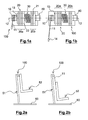
figures 2a et 2b illustrent de manière schématique une vue de principe de profil d'un siège comportant l'absorbeur d'énergie desfigures 1a et 1b , respectivement en position non déclenchée,figure 2a , et en position déclenchée,figure 2b , de l'absorbeur d'énergie ; - la
figure 3 montre en vue perspective un exemple de réalisation d'un absorbeur d'énergie à sangle intégré dans un boîtier suivant l'invention ; - la
figure 4 représente en vue perspective l'absorbeur d'énergie de lafigure 4 dont une face du boîtier n'est pas représentée pour montrer l'agencement des composants de l'absorbeur d'énergie ; - la
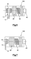
figure 5 représente une section suivant un plan axial de l'absorbeur d'énergie desfigures 3 et 4 montrant l'agencement des composants de l'absorbeur d'énergie ; - la
figure 6 illustrent de manière schématique une vue de principe d'un absorbeur d'énergie suivant l'invention comportant un tambour enrouleur avec deux câbles mis en oeuvre comme ligne de traction ; - la
figure 7 illustrent de manière schématique une vue de principe d'un absorbeur d'énergie suivant l'invention comportant un tambour enrouleur non cylindrique.
- the
Figures 1a and 1b schematically illustrate a principle view of an energy absorber according to the invention, the absorber being illustrated in a condition not triggered on thefigure 1a and in a condition triggered on thefigure 1b ; - the
Figures 2a and 2b schematically illustrate a basic profile view of a seat comprising the energy absorber ofFigures 1a and 1b , respectively in the non-triggered position,figure 2a , and in the triggered position,figure 2b , the energy absorber; - the
figure 3 shows in perspective view an embodiment of a belt energy absorber integrated in a housing according to the invention; - the
figure 4 represents in perspective the energy absorber of thefigure 4 one side of the housing is not shown to show the arrangement of the energy absorber components; - the
figure 5 represents a section along an axial plane of the energy absorber ofFigures 3 and 4 showing the arrangement of the components of the energy absorber; - the
figure 6 schematically illustrate a principle view of an energy absorber according to the invention comprising a reel drum with two cables used as a traction line; - the
figure 7 schematically illustrate a principle view of an energy absorber according to the invention comprising a non-cylindrical drum drum.
Les
"Avant déclenchement" signifie dans la présente description que l'absorbeur d'énergie n'a pas été soumis à des conditions ayant conduit ledit absorbeur d'énergie à absorber d'énergie et a contrario "après déclenchement" signifie que ledit absorbeur d'énergie a été soumis à des conditions dans lesquelles il a absorbé une énergie."Before firing" means in the present description that the energy absorber has not been subjected to conditions having led said energy absorber to absorb energy and a contrario "after firing" means that said absorber of energy energy has been subjected to conditions in which it has absorbed energy.
L'absorbeur d'énergie 100 comporte principalement :
- une ligne de
traction 11 réalisée dans un matériau souple et résistant ; un tambour enrouleur 10 ;un frein 20 ;un élément ressort 30- un organe de contrôle 40 de la force exercée
par l'élément ressort 30.
- a
pull line 11 made of a flexible and resistant material; - a winding
drum 10; - a
brake 20; - a
spring element 30 - a
control member 40 of the force exerted by thespring element 30.
L'absorbeur d'énergie comporte également un arbre 13 monté en rotation autour d'un axe 12 sur lequel sont fixés le tambour enrouleur 10 et un rotor 21 du frein de sorte que ledit tambour enrouleur et ledit rotor sont solidaires en rotation autour de l'axe 12.The energy absorber also comprises a
Le rotor 21 du frein est couplé en friction avec un stator 22 immobilisé en rotation, une force générée par l'élément ressort 30 assurant le couplage en friction dudit rotor et dudit stator formant le frein 20.The
L'organe de contrôle 40 agit sur l'élément ressort 30 pour modifier la force assurant le couplage en friction du rotor et du stator du frein.The
La ligne de traction 11 est fixée à une première extrémité au tambour enrouleur 10 sur lequel ladite ligne de traction est enroulées lorsque le dispositif 100 n'est pas déclenché comme illustré sur le schéma
Suivant cette configuration du dispositif 100, une force de traction exercée sur la ligne de traction 11, par exemple à une seconde extrémité libre 14 de ladite ligne de traction, génère un couple moteur sur l'arbre 13, fonction de la force de traction et de la distance d'application de ladite force à l'axe 12 donc fonction du diamètre du tambour enrouleur 10.According to this configuration of the
Tant que le couple moteur sur l'arbre 13 est inférieur à un couple frein maximum créé par le frein 20, l'arbre 13 reste bloqué en rotation et la ligne de traction 11 est également bloquée.As long as the engine torque on the
Lorsque la force de traction sur la ligne de traction 11 est augmentée jusqu'à une valeur conduisant à un couple moteur dépassant le couple frein maximum, l'arbre 13 est entraîné en rotation alors que le couple frein maximum est maintenu par le frein 20 et que la ligne de traction 11 est déroulée du tambour 13 comme illustré sur le schéma de la
Il en résulte que la force à laquelle est soumise la ligne de traction 11 est écrêtée à la valeur correspondant au couple frein maximum tant que ladite ligne de traction n'est pas totalement déroulée du tambour enrouleur 10.As a result, the force to which the
Lorsque la ligne de traction 11 est totalement déroulée du tambour enrouleur 10, la rotation de l'arbre 13 est arrêtée, la ligne de traction étant fixée audit tambour enrouleur à la première extrémité.When the
Il résulte de l'écrêtage de la force sur la ligne de traction 11 que lorsque cette force est le résultat d'une accélération Gamma sur une masse m donnée, ladite accélération Gamma est également écrêtée suivant la relation triviale "F = m Gamma".It results from the clipping of the force on the
Lorsqu'il est connu la masse, par exemple celle d'une partie mobile d'un siège et de son occupant qui ne doit pas subir une accélération supérieure à une valeur Gamma_max, il en est déduit la force Fmax qui doit être appliquée sur la ligne de traction et donc le couple frein maximum appliqué par le frein 20 au tambour enrouleur 10.When the mass is known, for example that of a mobile part of a seat and its occupant which must not undergo an acceleration greater than a value Gamma_max, it is deduced the force Fmax which must be applied to the traction line and therefore the maximum brake torque applied by the
Une action sur l'organe de contrôle 40 agit sur la force développée par l'élément ressort 30 et sur le couplage en friction du rotor et du stator du frein 20 et permet alors d'ajuster le couple frein maximum à la valeur correspondant à la masse considérée et à l'accélération souhaitée Gamma_max devant déclencher le glissement entre le stator et le rotor.An action on the
Avantageusement, l'organe de contrôle 40 comporte une commande graduée, par exemple en masse.Advantageously, the
Les
Le siège 50 comporte une structure porteuse 51 et un baquet 52 attaché à la structure porteuse.The seat 50 comprises a
Le baquet 52 est illustré de manière très simplifiée et représente la partie du siège qui avec l'occupant du siège est soumise à l'accélération, ici une accélération sensiblement verticale, qui doit être écrêtée. Suivant le type de siège le baquet peut par exemple être un baquet rigide dans lequel une assise et un dossier sont fixés rigidement ou comporter un dossier et une assise articulés entre eux.The
Le baquet 52 est monté sur des glissières ou autre dispositif de guidage par exemple articulé, non représentés, de la structure porteuse 51, de sorte à être guidé dans un déplacement suivant une direction dans laquelle l'accélération est écrêtée.The
Sur la
On comprend que dans l'exemple illustré l'accélération devant être écrêtée est une accélération sensiblement verticale (ou une composante sensiblement verticale de l'accélération subie par le siège) et orientée du bas vers le haut en réaction à un crash comportant une forte composante verticale.It is understood that in the illustrated example the acceleration to be clipped is a substantially vertical acceleration (or a substantially vertical component of the acceleration experienced by the seat) and oriented from the bottom up in response to a crash having a strong vertical component.
Dans cette configuration de la
Lorsque l'accélération, par exemple en cas de crash, produit sur la ligne de traction 11 une force générant un couple moteur supérieur au couple frein maximum de l'absorbeur d'énergie 100, il apparaît un glissement entre le stator 22 et le rotor 21 du frein qui limite le couple moteur à la valeur du couple frein maximum, ce qui a pour conséquence de limiter, pendant toute la durée du glissement, la force sur la ligne de traction 11 et donc l'accélération subie par l'occupant du siège.When the acceleration, for example in the event of a crash, produces on the traction line 11 a force generating a motor torque greater than the maximum brake torque of the
Le glissement entre le stator 22 et le rotor 21 cesse dès lors qu'il résulte que le couple moteur redevient inférieur au couple frein maximum ou que la ligne de traction 11 est totalement déroulée du tambour enrouleur 10.Sliding between the
En pratique, la longueur de ligne de traction 11 enroulée sur le tambour enrouleur 10 détermine la distance sur laquelle l'accélération subie est écrêtée et, si le couple frein maximum est ajusté à une valeur fonction de la masse retenue par la ligne de traction pour obtenir une accélération donnée fixe, détermine une durée sensiblement indépendante de la masse pendant laquelle l'accélération sera écrêtée à la valeur choisie.In practice, the length of
Cette durée qui est déterminée par les caractéristiques de l'absorbeur d'énergie 100 et qui peut être sensiblement constante quel que soit la masse, dans des limites opérationnelles acceptables, d'un occupant du siège correspond avantageusement au moins à la durée du pic d'accélération tel que prévue en cas de crash dans les normes, par exemple dans les normes aéronautiques des JAA et FAA, pour sa partie dépassant par exemple une accélération de 60m/s2 (facteur d'accélération de 6g environ). Dans le cas des conditions de crash d'un aéronef, une longueur de déplacement du baquet comprise entre 100mm et 200mm est généralement suffisante pour écrêter le pic d'accélération.This duration, which is determined by the characteristics of the
D'autres agencements de l'absorbeur d'énergie 100 sur le siège 50 sont possibles et qui permettent d'obtenir un résultat similaire.Other arrangements of the
Par exemple l'absorbeur d'énergie 100 peut être fixé au baquet 52 et l'extrémité libre 14 de la ligne de traction fixée à la structure porteuse 51.For example, the
Des configurations avec un renvoi de la ligne de traction, par exemple par des poulies, sont également possibles pour autant que la ligne de traction entre le baquet 52 et la structure porteuse 51 ait une orientation voisine de la direction de l'accélération devant être écrêtée. En pratique il sera cependant évité les solutions qui introduiraient des jeux ou un allongement excessif de la ligne de traction, en raison de risques d'allongement élastique de ladite ligne de traction, et les solutions qui conduiraient à un alourdissement excessif de la partie du siège devant être soumise à la traction de la ligne de traction et devant être freinée.Configurations with a return of the traction line, for example by pulleys, are also possible as long as the line of traction between the
Les
Sur la
L'absorbeur d'énergie se présente sous la forme générale d'un boîtier 101 parallélépipède rectangle avec deux faces d'extrémité 103 sensiblement carrées et allongé suivant la dimension perpendiculaire aux faces d'extrémité.The energy absorber is in the general form of a
L'axe 12 est parallèle aux arrêtes des faces allongées et passe sensiblement par des centres des faces d'extrémité 103.The
Le boîtier 101 comporte également des pattes de fixation 102, en nombre et en disposition sur ledit boîtier nécessaire pour fixer ledit boîtier sur une structure porteuse ou sur le baquet d'un siège.The
Au moins un organe de contrôle 40 est accessible depuis l'extérieur du boîtier 101. Dans l'exemple illustré l'organe de contrôle est terminé par une poignée 41, pouvant être entraînée en rotation à la main ou à l'aide d'un outil tel qu'une clé, située sur une des faces d'extrémité 103.At least one
La ligne traction 11 est réalisée avec une sangle dont l'extrémité libre 14 comporte une boucle d'attache 141, par exemple une boucle métallique.The
La ligne de traction 11 sort du boîtier 101 par une ouverture 104 de forme relativement étroite et allongée pour laisser un passage libre à la sangle de la ligne de traction 11 et éviter/limiter le risque de pénétration de corps étrangers.The pulling
La
Du côté d'une première extrémité du boîtier 101, à gauche sur les
Du côté d'une seconde extrémité du boîtier 101, à droite sur les
Le stator 22 de frein comporte un ensemble d'éléments de friction 222 bloqués en rotation par le boîtier 101, et indépendant de l'arbre 13 d'axe 12. Les éléments de friction 222 du stator sont libres en translation, sur une distance suffisante pour garantir le fonctionnement du frein, de sorte à pouvoir se déplacer suivant la direction de l'axe 12 par rapport au boîtier et par rapport à l'arbre 13.The
Le blocage en rotation dans le boîtier des éléments de friction 222 est par exemple obtenu par une forme des dits éléments de friction ajustée à la forme intérieure du boîtier, par exemple carré, qui maintien les éléments de stator immobiles en rotation autour de l'axe 12 tout en autorisant un glissement longitudinal dans un tube de section carrée formé par le boîtier.The locking in rotation in the housing of the
Le rotor 21 de frein comporte un ensemble d'éléments de friction 211 montés entraînés en rotation avec l'arbre 13. Les éléments de friction 211 du stator sont libres en translation sur l'arbre 13 de sorte à pouvoir se déplacer suivant la direction de l'axe 12 par rapport au boîtier et par rapport à l'arbre 13. Un tel résultat est par exemple obtenu avec un arbre cannelé et une forme d'un trou central des éléments de friction du rotor comportant des dents complémentaires des cannelures de l'arbre.The
Les éléments de friction 221 du rotor sont par exemple des disques dont un diamètre extérieur est choisi pour que les dits disques puissent tourner sans interférence avec les parois intérieure du boîtier.The
Les éléments de friction 211 du stator et les éléments de friction 222 du stator sont montés alternés sur l'arbre 13 et forment ainsi un frein à disques, le nombre de disques permettant d'obtenir des capacités du frein à créer un couple frein maximum souhaité sans augmenter de manière excessive la dimension des disques et ou la force nécessaire pour créer entre le stator et le rotor la friction nécessaire.The
De manière connue les surfaces en contact entre les éléments de rotor et de stator sont relativement lisses, ou au moins adaptées pour permettre un glissement entre les éléments en contact.In known manner, the surfaces in contact between the rotor elements and stator are relatively smooth, or at least adapted to allow a sliding between the elements in contact.
Les matériaux permettant d'obtenir un glissement avec friction sont connus et dans le cas de l'absorbeur d'énergie 100, il sera préféré des matériaux dont la force de friction statique, sans rotation du rotor, est égale ou proche de la force de friction dynamique lorsque le rotor est en rotation.Materials for sliding friction are known and in the case of the
Il doit également être noté que le frein 20 est destiné à rester statique sur de longue période et à fonctionner sur un nombre limité de tours et un nombre limité de fois, pour l'essentiel lors de tests de bon fonctionnement.It should also be noted that the
Les matériaux des éléments du stator et du rotor seront donc choisis pour éviter des risques de collage alors que leurs capacités à résister à une usure en utilisation ne sont pas critiques dans le cas de l'absorbeur d'énergie 100.The materials of the stator and rotor elements will therefore be chosen to avoid sticking risks while their ability to resist wear in use are not critical in the case of the
L'élément ressort 30 est placé entre les deux sous-ensembles 20a, 20b du frein 20 de sorte à être comprimé entre lesdits deux sous-ensembles de frein pour obtenir une force d'application de faces en contact des éléments de stator et de rotor.The
L'élément ressort 30 consiste dans l'exemple illustré en un bloc d'un matériau rigide avec des propriétés élastiques usiné pour permettre une déformation élastique suivant la direction de l'axe 12.The
La forme de l'élément ressort en assure l'immobilisation en rotation dans le boîtier 101 sans en interdire le déplacement suivant la direction de l'axe. Ce choix qui n'est pas obligatoire permet cependant de limiter la masse tournante dans l'absorbeur d'énergie et donc les effets transitoires sur la vitesse de rotation lors d'un déclenchement de l'absorbeur d'énergie.The shape of the spring element ensures rotational immobilization in the
Dans ce cas il est préféré que l'élément ressort 30 prenne appui, comme illustré, sur des éléments de stator pour éviter une friction sur ledit élément ressort dont le matériau n'est pas choisi pour ses propriétés de friction. Toutefois il est possible de déposer sur des faces de l'élément ressort un matériau de friction si ledit élément ressort est en contact avec un ou des éléments de rotor.In this case it is preferred that the
Il doit également être pris en considération que l'élément ressort 30 reste comprimé en permanence, dans l'attente d'un éventuel déclenchement de l'absorbeur d'énergie 100, et qu'il doit donc conserver son élasticité dans ces conditions de sorte à maintenir, sous un écrasement donné et maintenu, une force de pression entre les éléments de stator et de rotor sensiblement constante tout au long d'une durée de vie opérationnelle de l'absorbeur d'énergie.It must also be taken into account that the
L'élément ressort peut être réalisé dans un acier ou dans un matériau polymère chargé ou non de fibres.The spring element may be made of a steel or a polymer material loaded or not with fibers.
L'organe de contrôle 40 comporte un élément d'appui 42 dont la position suivant la direction de l'axe 12 est ajustable. La position de l'élément d'appui 42 est par exemple ajustée par un filetage 43 d'une vis de l'organe de contrôle 40 qui coopère avec un trou taraudé du boîtier 101, la vis étant pourvue à une extrémité extérieure au dit boîtier d'une poignée 41, par exemple un bouton moleté, et ou d'une forme adaptée pour être entraînée en rotation à visser ou à dévisser par un outil.The
Le cas échéant, l'organe de contrôle comporte des moyens de blocage en rotation, non représentés, pour éviter un serrage ou un desserrage non commandé de la vis par exemple sous l'effet de vibrations.Where appropriate, the control member comprises rotational locking means, not shown, to prevent clamping or loosening not controlled the screw for example under the effect of vibration.
L'élément d'appui 42 est situé du côté d'une face extérieure d'un premier élément 221 de stator contre lequel il exerce la force d'appui pour obtenir une compression voulue de l'élément ressort. En étant ainsi en appui contre un élément non tournant du frein 20, il est évité d'introduire des forces pouvant provoquer un serrage ou un desserrage de l'organe de contrôle 40 lors d'un déclenchement de l'absorbeur d'énergie.The
L'arbre 13 comporte également un épaulement 134 situé du côté d'une face extérieure d'un dernier élément 212 de rotor situé à une extrémité opposée du frein 20 par rapport au premier élément 221 de stator. Il doit être noté que le dernier élément 212 de rotor est entraîné en rotation avec l'arbre 13 et qu'il est donc avantageusement immobile en rotation par rapport à l'épaulement 134.The
Suivant cet agencement, l'ensemble des éléments de stator et de rotor ainsi que l'élément ressort 30 sont disposés sur l'arbre 13 entre l'épaulement 134 et l'élément d'appui 42.According to this arrangement, all the stator and rotor elements and the
Lorsque l'élément d'appui 43 est suffisamment rapproché de l'épaulement 134, les surfaces en vis à vis des éléments de rotor et de stator sont en contact et soumises à une pression établie par la force avec laquelle l'élément ressort 30 est comprimé.When the
Il en résulte un couple frein maximum qui interdit la rotation du rotor 21 et donc de l'arbre 13 tant qu'aucun couple moteur supérieur au couple frein maximum n'est appliqué audit arbre par une traction sur la sangle de la ligne de traction, couple frein maximum qui peut être modifié par une action sur la poignée 41 à visser pour augmenter le couple frein maximum ou à dévisser pour diminuer le couple frein maximum.This results in a maximum brake torque which prevents rotation of the
Un tel réglage est rendu accessible par la poignée 41 lorsque l'absorbeur d'énergie 100 est fixé sur une structure d'un siège 50 de sorte que le couple frein maximum peut être modifié en fonction de la masse de l'occupant du siège.Such an adjustment is made accessible by the
La poignée 41 comporte par exemple un indicateur de position gradué en masse de sorte à obtenir un déclenchement de l'absorbeur d'énergie 100 pour une accélération sensiblement constante avec les différentes masses des occupants possibles du siège.The
Pour assurer un fonctionnement optimal de l'absorbeur d'énergie, l'arbre 13 est maintenu centré sur l'axe 12 par des paliers d'extrémités 131, 132 ou intermédiaire 133 de sorte à limiter au mieux les frottements parasites et les désaxements qui perturberaient le couple frein contrôlé par le frein 20.To ensure optimal operation of the energy absorber, the
Le mode de réalisation détaillé décrit n'est qu'un exemple non limitatif d'une forme de réalisation.The detailed embodiment described is only a non-limiting example of one embodiment.
Par exemple la ligne de traction peut être une ou plusieurs sangles, comme dans l'exemple détaillé, un ou plusieurs câbles ou une chaîne, le tambour enrouleur étant alors adapté au type de ligne de traction mis en oeuvre.For example, the pulling line may be one or more straps, as in the detailed example, one or more cables or a chain, the drum drum then being adapted to the type of traction line used.
Suivant le schéma de principe de la
Suivant une autre variante présentée sur le schéma de principe de la
Lorsque l'absorbeur d'énergie est déclenché, la force de traction correspondant au couple frein maximum est alors différente suivant la position du câble sur le tambour enrouleur, plus faible lorsque le diamètre local du tambour est plus grand et plus forte lorsque le diamètre local du tambour est plus petit.When the energy absorber is triggered, the traction force corresponding to the maximum brake torque is then different according to the position of the cable on the drum drum, lower when the local diameter of the drum is larger and stronger when the local diameter drum is smaller.
Il est ainsi possible d'obtenir en mode déclenché de l'absorbeur d'énergie un profil variable de l'accélération subie par l'occupant du siège.It is thus possible to obtain in the triggered mode of the energy absorber a variable profile of the acceleration experienced by the occupant of the seat.
Un tel profil variable permet par exemple de diminuer la force sur la ligne de traction nécessaire pour initier la rotation du frein, le couple frein maximum pouvant être au début du mouvement plus important du fait même de la conception du frein ou du fait d'un collage lié à une durée importante passée sans rotation, et pour reprendre ensuite une accélération d'écrêtage souhaitée.Such a variable profile makes it possible, for example, to reduce the force on the line of traction necessary to initiate the rotation of the brake, the maximum brake torque may be at the beginning of the larger movement because of the brake design or due to a bonding related to a long time passed without rotation, and then to resume desired clipping acceleration.
Une forme conique du tambour enrouleur comme représenté sur la
Il doit être noté qu'un effet similaire est obtenu lorsque la ligne de traction est réalisée avec une sangle d'épaisseur non négligeable, le rayon apparent du tambour étant fonction du nombre de tours encore enroulés sur ledit tambour et diminuant progressivement lorsque la sangle se déroule.It should be noted that a similar effect is obtained when the pulling line is made with a strap of significant thickness, the apparent radius of the drum being a function of the number of turns still wound on said drum and gradually decreasing when the strap is place.
D'autres formes de frein, non illustrées, sont également possibles comme par exemple des rotors en forme de tambour sur une surface enveloppe cylindrique duquel des patins sont appliqués avec plus ou moins de force et ou en plus ou moins grand nombre pour obtenir le couple frein souhaité.Other forms of brake, not illustrated, are also possible such as drum-shaped rotors on a cylindrical envelope surface of which pads are applied with more or less force and or more or less to obtain the couple desired brake.
Dans une forme de réalisation, non illustrées, l'arbre entraîné en rotation par le tambour est immobilisé par rapport à un boîtier de l'absorbeur d'énergie au moyen d'un fusible calibré, par exemple une goupille montée en cisaillement.In one embodiment, not shown, the shaft rotated by the drum is immobilized with respect to a casing of the energy absorber by means of a calibrated fuse, for example a pin mounted in shear.
Le calibre de ladite goupille est choisi de sorte que celle-ci soit cisaillée lorsqu'il est appliqué au tambour le couple correspondant à la force sur la ligne de traction devant déclencher le fonctionnement de l'absorbeur d'énergie.The caliper of said pin is chosen so that it is sheared when applied to the drum torque corresponding to the force on the pull line to trigger the operation of the energy absorber.
Ainsi il est évité un possible glissement du frein, par exemple du fait d'un environnement vibratoire intense, sans que la force de déclenchement, ou au moins du déclenchement du fusible, ne soit atteinte ou dépassée.Thus it is avoided a possible sliding of the brake, for example due to an intense vibratory environment, without the triggering force, or at least fuse tripping, is reached or exceeded.
Lorsque la force écrêtée et le couple frein correspondant sont fonction du réglage appliqué à l'absorbeur d'énergie, il sera choisi un calibre du fusible prenant en compte la plus petite force devant déclencher le fonctionnement de l'absorbeur d'énergie.When the clipped force and the corresponding brake torque are a function of the adjustment applied to the energy absorber, a fuse rating will be chosen taking into account the smallest force to trigger the operation of the energy absorber.
Dans ce mode de réalisation, il sera également de préférence pris la précaution de retirer le fusible pour réaliser les essais du frein sauf à remplacer ledit fusible après l'essai.In this embodiment, it will also preferably take the precaution to remove the fuse to perform the brake tests except to replace said fuse after the test.
Il doit également être compris que le tambour enrouleur est couplé mécaniquement au frein de sorte à subir le couple frein mais que le frein n'est pas nécessairement monté sur le même axe de rotation que le tambour enrouleur, des transmissions mécaniques présentant par exemple des renvois d'angle ou d'autres dispositifs de couplage étant possibleIt should also be understood that the drum drum is mechanically coupled to the brake so as to undergo the brake torque but that the brake is not necessarily mounted on the same axis of rotation as the winding drum, mechanical transmissions having for example angle returns or other coupling devices being possible
Dans une forme de réalisation, le réglage du frein en fonction du poids est assuré de manière automatique, par exemple par un système de mesure du poids de l'occupant du siège en condition statique et un dispositif tel qu'un actionneur électrique agissant sur l'organe de contrôle en fonction dudit poids mesuré.In one embodiment, the adjustment of the brake according to the weight is ensured automatically, for example by a system for measuring the weight of the occupant of the seat in static condition and a device such as an electric actuator acting on the control member as a function of said measured weight.
Il est ainsi obtenu un absorbeur d'énergie pour siège et un siège pouvant être soumis à des accélérations de crash qui permettent de limiter l'accélération subie par un occupant du siège en prenant en compte la masse dudit occupant.It is thus obtained a seat energy absorber and a seat that can be subjected to crash accelerations that limit the acceleration experienced by a seat occupant taking into account the mass of said occupant.
En outre le fonctionnement du système n'est pas destructeur ce qui permet de tester le fonctionnement correct de l'absorbeur d'énergie, par exemple avant sa mise en service ou de manière périodique, et de remettre celui en condition de fonctionner à nouveau.In addition, the operation of the system is not destructive, which makes it possible to test the correct operation of the energy absorber, for example before it is put into service or periodically, and to restore the conditioner to function again.
Claims (12)
Applications Claiming Priority (1)
| Application Number | Priority Date | Filing Date | Title |
|---|---|---|---|
| FR1362027A FR3014156B1 (en) | 2013-12-03 | 2013-12-03 | ENERGY ABSORBER FOR ANTICRASH SEAT AND ANTICRASH SEAT COMPRISING SUCH AN ENERGY ABSORBER |
Publications (2)
| Publication Number | Publication Date |
|---|---|
| EP2886906A1 true EP2886906A1 (en) | 2015-06-24 |
| EP2886906B1 EP2886906B1 (en) | 2019-02-06 |
Family
ID=50489204
Family Applications (1)
| Application Number | Title | Priority Date | Filing Date |
|---|---|---|---|
| EP14196110.2A Active EP2886906B1 (en) | 2013-12-03 | 2014-12-03 | Energy absorber for anti-crash seat and an anti-crash seat with such an absorber. |
Country Status (3)
| Country | Link |
|---|---|
| US (1) | US9399518B2 (en) |
| EP (1) | EP2886906B1 (en) |
| FR (1) | FR3014156B1 (en) |
Families Citing this family (2)
| Publication number | Priority date | Publication date | Assignee | Title |
|---|---|---|---|---|
| US11066171B2 (en) * | 2016-04-04 | 2021-07-20 | B/E Aerospace, Inc. | Contoured class divider |
| US20230312096A1 (en) * | 2022-03-31 | 2023-10-05 | B/E Aerospace, Inc. | Fuse link head impact criteria mitigating device |
Citations (8)
| Publication number | Priority date | Publication date | Assignee | Title |
|---|---|---|---|---|
| DE384073C (en) * | 1921-11-29 | 1923-10-25 | Louis Renault | Shock absorbers, especially for motor vehicles |
| DE434164C (en) * | 1925-04-04 | 1926-09-21 | Hans Ludwig | Friction shock absorbers, especially for motor vehicles |
| US3985388A (en) | 1975-08-11 | 1976-10-12 | Uop Inc. | Vertically adjustable seat with energy absorbing means |
| EP0075067A1 (en) * | 1981-09-21 | 1983-03-30 | ARA, Inc. | Variable energy absorbing system for crashworthy helicopter seats |
| US4440441A (en) | 1981-12-17 | 1984-04-03 | Fairchild Industries, Inc. | Energy attenuating seat and leg therefor |
| EP0716980A1 (en) * | 1994-12-13 | 1996-06-19 | EUROCOPTER FRANCE, Société Anonyme dite: | Crashworthy aircraft seat with a harness |
| US7921973B2 (en) | 2006-05-31 | 2011-04-12 | Techno-Sciences, Inc. | Adaptive energy absorption system for a vehicle seat |
| EP2360095A1 (en) * | 2010-02-23 | 2011-08-24 | Eurocopter | Anti-crash vehicle seat |
Family Cites Families (2)
| Publication number | Priority date | Publication date | Assignee | Title |
|---|---|---|---|---|
| US1656744A (en) * | 1927-01-08 | 1928-01-17 | Charles W Manzel | Hydraulic shock absorber |
| JP2007321835A (en) * | 2006-05-31 | 2007-12-13 | Matsushita Electric Ind Co Ltd | Damper device |
-
2013
- 2013-12-03 FR FR1362027A patent/FR3014156B1/en active Active
-
2014
- 2014-12-03 EP EP14196110.2A patent/EP2886906B1/en active Active
- 2014-12-03 US US14/559,137 patent/US9399518B2/en active Active
Patent Citations (8)
| Publication number | Priority date | Publication date | Assignee | Title |
|---|---|---|---|---|
| DE384073C (en) * | 1921-11-29 | 1923-10-25 | Louis Renault | Shock absorbers, especially for motor vehicles |
| DE434164C (en) * | 1925-04-04 | 1926-09-21 | Hans Ludwig | Friction shock absorbers, especially for motor vehicles |
| US3985388A (en) | 1975-08-11 | 1976-10-12 | Uop Inc. | Vertically adjustable seat with energy absorbing means |
| EP0075067A1 (en) * | 1981-09-21 | 1983-03-30 | ARA, Inc. | Variable energy absorbing system for crashworthy helicopter seats |
| US4440441A (en) | 1981-12-17 | 1984-04-03 | Fairchild Industries, Inc. | Energy attenuating seat and leg therefor |
| EP0716980A1 (en) * | 1994-12-13 | 1996-06-19 | EUROCOPTER FRANCE, Société Anonyme dite: | Crashworthy aircraft seat with a harness |
| US7921973B2 (en) | 2006-05-31 | 2011-04-12 | Techno-Sciences, Inc. | Adaptive energy absorption system for a vehicle seat |
| EP2360095A1 (en) * | 2010-02-23 | 2011-08-24 | Eurocopter | Anti-crash vehicle seat |
Also Published As
| Publication number | Publication date |
|---|---|
| US9399518B2 (en) | 2016-07-26 |
| EP2886906B1 (en) | 2019-02-06 |
| FR3014156B1 (en) | 2017-10-13 |
| US20150151841A1 (en) | 2015-06-04 |
| FR3014156A1 (en) | 2015-06-05 |
Similar Documents
| Publication | Publication Date | Title |
|---|---|---|
| FR2491340A1 (en) | RECALL TENSIONER FOR AN AUTOMATIC BELT TENSIONER | |
| EP0030494A1 (en) | Mechanical control by Bowden cable | |
| EP0466540A1 (en) | Vibration damping device | |
| FR2489155A1 (en) | DEVICE FOR LOCKING THE BELT TAPE FOR THE SAFETY BELTS OF MOTOR VEHICLES | |
| EP3981618B1 (en) | Device for controlling the pressure of a tyre of an aircraft wheel | |
| EP2886906B1 (en) | Energy absorber for anti-crash seat and an anti-crash seat with such an absorber. | |
| FR2828543A1 (en) | Double damped flywheel, especially for motor vehicle, has cam follower moving over cam profile through 360 deg round axis of flywheel's rotation | |
| WO2016050611A1 (en) | Torsional damper with blade | |
| EP3747518A1 (en) | Double pulley | |
| EP2058544B1 (en) | Vibration damper for disk brake | |
| EP2995479B1 (en) | Anti-slip device for a motor vehicle wheel | |
| FR3014518A1 (en) | DOUBLE SHOCKWHEEL WITH ROTATION BLOCKING DEVICE OF ITS PRIMARY AND SECONDARY WHEELS | |
| FR2910578A1 (en) | Engine's e.g. petrol engine, belt tensioning device for e.g. automobile, has unit blocking and unblocking movement of arm with respect to plate according to operation speed of engine, where unit is constituted by cam, spring and bearings | |
| FR2914600A1 (en) | STOPPER FOR THE PROTECTION OF A FIRST ELEMENT AT THE MEETING WITH A SECOND ELEMENT. | |
| FR3061315A1 (en) | TRAINING DEVICE | |
| EP2998835A1 (en) | Data input device and braking means thereof | |
| FR3039458A1 (en) | HUB FOR CYCLE WHEEL | |
| FR2462172A1 (en) | SECURITY BELT REEL | |
| EP3325299B1 (en) | Pivot device | |
| FR2817601A1 (en) | Double damping flywheel has temporary immobilizer for use on assembly of primary and secondary flywheels, made in form of movable tool with ring and tubes engaging with cavities in two and equipped with extractor | |
| EP2813387A1 (en) | Connecting rod between two movable members | |
| FR3132274A1 (en) | Sliding door travel speed control system and associated aircraft | |
| WO2016198452A1 (en) | Torsion damper | |
| EP1936228A1 (en) | System for control by cable of an automatic parking brake | |
| WO2023144483A1 (en) | Device for transmitting a movement |
Legal Events
| Date | Code | Title | Description |
|---|---|---|---|
| PUAI | Public reference made under article 153(3) epc to a published international application that has entered the european phase |
Free format text: ORIGINAL CODE: 0009012 |
|
| 17P | Request for examination filed |
Effective date: 20141203 |
|
| AK | Designated contracting states |
Kind code of ref document: A1 Designated state(s): AL AT BE BG CH CY CZ DE DK EE ES FI FR GB GR HR HU IE IS IT LI LT LU LV MC MK MT NL NO PL PT RO RS SE SI SK SM TR |
|
| AX | Request for extension of the european patent |
Extension state: BA ME |
|
| R17P | Request for examination filed (corrected) |
Effective date: 20151224 |
|
| RBV | Designated contracting states (corrected) |
Designated state(s): AL AT BE BG CH CY CZ DE DK EE ES FI FR GB GR HR HU IE IS IT LI LT LU LV MC MK MT NL NO PL PT RO RS SE SI SK SM TR |
|
| RIC1 | Information provided on ipc code assigned before grant |
Ipc: B60N 2/42 20060101ALI20180620BHEP Ipc: B60N 2/427 20060101ALI20180620BHEP Ipc: F16F 7/04 20060101AFI20180620BHEP |
|
| GRAP | Despatch of communication of intention to grant a patent |
Free format text: ORIGINAL CODE: EPIDOSNIGR1 |
|
| STAA | Information on the status of an ep patent application or granted ep patent |
Free format text: STATUS: GRANT OF PATENT IS INTENDED |
|
| INTG | Intention to grant announced |
Effective date: 20180731 |
|
| GRAS | Grant fee paid |
Free format text: ORIGINAL CODE: EPIDOSNIGR3 |
|
| GRAA | (expected) grant |
Free format text: ORIGINAL CODE: 0009210 |
|
| STAA | Information on the status of an ep patent application or granted ep patent |
Free format text: STATUS: THE PATENT HAS BEEN GRANTED |
|
| AK | Designated contracting states |
Kind code of ref document: B1 Designated state(s): AL AT BE BG CH CY CZ DE DK EE ES FI FR GB GR HR HU IE IS IT LI LT LU LV MC MK MT NL NO PL PT RO RS SE SI SK SM TR |
|
| REG | Reference to a national code |
Ref country code: GB Ref legal event code: FG4D Free format text: NOT ENGLISH |
|
| REG | Reference to a national code |
Ref country code: CH Ref legal event code: EP Ref country code: AT Ref legal event code: REF Ref document number: 1095110 Country of ref document: AT Kind code of ref document: T Effective date: 20190215 |
|
| REG | Reference to a national code |
Ref country code: IE Ref legal event code: FG4D Free format text: LANGUAGE OF EP DOCUMENT: FRENCH |
|
| REG | Reference to a national code |
Ref country code: DE Ref legal event code: R096 Ref document number: 602014040681 Country of ref document: DE |
|
| REG | Reference to a national code |
Ref country code: NL Ref legal event code: MP Effective date: 20190206 |
|
| REG | Reference to a national code |
Ref country code: LT Ref legal event code: MG4D |
|
| PG25 | Lapsed in a contracting state [announced via postgrant information from national office to epo] |
Ref country code: FI Free format text: LAPSE BECAUSE OF FAILURE TO SUBMIT A TRANSLATION OF THE DESCRIPTION OR TO PAY THE FEE WITHIN THE PRESCRIBED TIME-LIMIT Effective date: 20190206 Ref country code: LT Free format text: LAPSE BECAUSE OF FAILURE TO SUBMIT A TRANSLATION OF THE DESCRIPTION OR TO PAY THE FEE WITHIN THE PRESCRIBED TIME-LIMIT Effective date: 20190206 Ref country code: NL Free format text: LAPSE BECAUSE OF FAILURE TO SUBMIT A TRANSLATION OF THE DESCRIPTION OR TO PAY THE FEE WITHIN THE PRESCRIBED TIME-LIMIT Effective date: 20190206 Ref country code: NO Free format text: LAPSE BECAUSE OF FAILURE TO SUBMIT A TRANSLATION OF THE DESCRIPTION OR TO PAY THE FEE WITHIN THE PRESCRIBED TIME-LIMIT Effective date: 20190506 Ref country code: SE Free format text: LAPSE BECAUSE OF FAILURE TO SUBMIT A TRANSLATION OF THE DESCRIPTION OR TO PAY THE FEE WITHIN THE PRESCRIBED TIME-LIMIT Effective date: 20190206 Ref country code: PT Free format text: LAPSE BECAUSE OF FAILURE TO SUBMIT A TRANSLATION OF THE DESCRIPTION OR TO PAY THE FEE WITHIN THE PRESCRIBED TIME-LIMIT Effective date: 20190606 |
|
| REG | Reference to a national code |
Ref country code: AT Ref legal event code: MK05 Ref document number: 1095110 Country of ref document: AT Kind code of ref document: T Effective date: 20190206 |
|
| PG25 | Lapsed in a contracting state [announced via postgrant information from national office to epo] |
Ref country code: RS Free format text: LAPSE BECAUSE OF FAILURE TO SUBMIT A TRANSLATION OF THE DESCRIPTION OR TO PAY THE FEE WITHIN THE PRESCRIBED TIME-LIMIT Effective date: 20190206 Ref country code: HR Free format text: LAPSE BECAUSE OF FAILURE TO SUBMIT A TRANSLATION OF THE DESCRIPTION OR TO PAY THE FEE WITHIN THE PRESCRIBED TIME-LIMIT Effective date: 20190206 Ref country code: IS Free format text: LAPSE BECAUSE OF FAILURE TO SUBMIT A TRANSLATION OF THE DESCRIPTION OR TO PAY THE FEE WITHIN THE PRESCRIBED TIME-LIMIT Effective date: 20190606 Ref country code: LV Free format text: LAPSE BECAUSE OF FAILURE TO SUBMIT A TRANSLATION OF THE DESCRIPTION OR TO PAY THE FEE WITHIN THE PRESCRIBED TIME-LIMIT Effective date: 20190206 Ref country code: BG Free format text: LAPSE BECAUSE OF FAILURE TO SUBMIT A TRANSLATION OF THE DESCRIPTION OR TO PAY THE FEE WITHIN THE PRESCRIBED TIME-LIMIT Effective date: 20190506 Ref country code: GR Free format text: LAPSE BECAUSE OF FAILURE TO SUBMIT A TRANSLATION OF THE DESCRIPTION OR TO PAY THE FEE WITHIN THE PRESCRIBED TIME-LIMIT Effective date: 20190507 |
|
| PG25 | Lapsed in a contracting state [announced via postgrant information from national office to epo] |
Ref country code: AL Free format text: LAPSE BECAUSE OF FAILURE TO SUBMIT A TRANSLATION OF THE DESCRIPTION OR TO PAY THE FEE WITHIN THE PRESCRIBED TIME-LIMIT Effective date: 20190206 Ref country code: ES Free format text: LAPSE BECAUSE OF FAILURE TO SUBMIT A TRANSLATION OF THE DESCRIPTION OR TO PAY THE FEE WITHIN THE PRESCRIBED TIME-LIMIT Effective date: 20190206 Ref country code: CZ Free format text: LAPSE BECAUSE OF FAILURE TO SUBMIT A TRANSLATION OF THE DESCRIPTION OR TO PAY THE FEE WITHIN THE PRESCRIBED TIME-LIMIT Effective date: 20190206 Ref country code: SK Free format text: LAPSE BECAUSE OF FAILURE TO SUBMIT A TRANSLATION OF THE DESCRIPTION OR TO PAY THE FEE WITHIN THE PRESCRIBED TIME-LIMIT Effective date: 20190206 Ref country code: RO Free format text: LAPSE BECAUSE OF FAILURE TO SUBMIT A TRANSLATION OF THE DESCRIPTION OR TO PAY THE FEE WITHIN THE PRESCRIBED TIME-LIMIT Effective date: 20190206 Ref country code: EE Free format text: LAPSE BECAUSE OF FAILURE TO SUBMIT A TRANSLATION OF THE DESCRIPTION OR TO PAY THE FEE WITHIN THE PRESCRIBED TIME-LIMIT Effective date: 20190206 Ref country code: DK Free format text: LAPSE BECAUSE OF FAILURE TO SUBMIT A TRANSLATION OF THE DESCRIPTION OR TO PAY THE FEE WITHIN THE PRESCRIBED TIME-LIMIT Effective date: 20190206 |
|
| REG | Reference to a national code |
Ref country code: DE Ref legal event code: R097 Ref document number: 602014040681 Country of ref document: DE |
|
| PG25 | Lapsed in a contracting state [announced via postgrant information from national office to epo] |
Ref country code: SM Free format text: LAPSE BECAUSE OF FAILURE TO SUBMIT A TRANSLATION OF THE DESCRIPTION OR TO PAY THE FEE WITHIN THE PRESCRIBED TIME-LIMIT Effective date: 20190206 Ref country code: PL Free format text: LAPSE BECAUSE OF FAILURE TO SUBMIT A TRANSLATION OF THE DESCRIPTION OR TO PAY THE FEE WITHIN THE PRESCRIBED TIME-LIMIT Effective date: 20190206 |
|
| PLBE | No opposition filed within time limit |
Free format text: ORIGINAL CODE: 0009261 |
|
| STAA | Information on the status of an ep patent application or granted ep patent |
Free format text: STATUS: NO OPPOSITION FILED WITHIN TIME LIMIT |
|
| PG25 | Lapsed in a contracting state [announced via postgrant information from national office to epo] |
Ref country code: AT Free format text: LAPSE BECAUSE OF FAILURE TO SUBMIT A TRANSLATION OF THE DESCRIPTION OR TO PAY THE FEE WITHIN THE PRESCRIBED TIME-LIMIT Effective date: 20190206 |
|
| 26N | No opposition filed |
Effective date: 20191107 |
|
| PG25 | Lapsed in a contracting state [announced via postgrant information from national office to epo] |
Ref country code: SI Free format text: LAPSE BECAUSE OF FAILURE TO SUBMIT A TRANSLATION OF THE DESCRIPTION OR TO PAY THE FEE WITHIN THE PRESCRIBED TIME-LIMIT Effective date: 20190206 |
|
| PG25 | Lapsed in a contracting state [announced via postgrant information from national office to epo] |
Ref country code: TR Free format text: LAPSE BECAUSE OF FAILURE TO SUBMIT A TRANSLATION OF THE DESCRIPTION OR TO PAY THE FEE WITHIN THE PRESCRIBED TIME-LIMIT Effective date: 20190206 |
|
| REG | Reference to a national code |
Ref country code: CH Ref legal event code: PL |
|
| REG | Reference to a national code |
Ref country code: BE Ref legal event code: MM Effective date: 20191231 |
|
| PG25 | Lapsed in a contracting state [announced via postgrant information from national office to epo] |
Ref country code: MC Free format text: LAPSE BECAUSE OF FAILURE TO SUBMIT A TRANSLATION OF THE DESCRIPTION OR TO PAY THE FEE WITHIN THE PRESCRIBED TIME-LIMIT Effective date: 20190206 |
|
| GBPC | Gb: european patent ceased through non-payment of renewal fee |
Effective date: 20191203 |
|
| PG25 | Lapsed in a contracting state [announced via postgrant information from national office to epo] |
Ref country code: LU Free format text: LAPSE BECAUSE OF NON-PAYMENT OF DUE FEES Effective date: 20191203 Ref country code: IE Free format text: LAPSE BECAUSE OF NON-PAYMENT OF DUE FEES Effective date: 20191203 Ref country code: GB Free format text: LAPSE BECAUSE OF NON-PAYMENT OF DUE FEES Effective date: 20191203 |
|
| PG25 | Lapsed in a contracting state [announced via postgrant information from national office to epo] |
Ref country code: BE Free format text: LAPSE BECAUSE OF NON-PAYMENT OF DUE FEES Effective date: 20191231 Ref country code: LI Free format text: LAPSE BECAUSE OF NON-PAYMENT OF DUE FEES Effective date: 20191231 Ref country code: CH Free format text: LAPSE BECAUSE OF NON-PAYMENT OF DUE FEES Effective date: 20191231 |
|
| PG25 | Lapsed in a contracting state [announced via postgrant information from national office to epo] |
Ref country code: CY Free format text: LAPSE BECAUSE OF FAILURE TO SUBMIT A TRANSLATION OF THE DESCRIPTION OR TO PAY THE FEE WITHIN THE PRESCRIBED TIME-LIMIT Effective date: 20190206 |
|
| PG25 | Lapsed in a contracting state [announced via postgrant information from national office to epo] |
Ref country code: HU Free format text: LAPSE BECAUSE OF FAILURE TO SUBMIT A TRANSLATION OF THE DESCRIPTION OR TO PAY THE FEE WITHIN THE PRESCRIBED TIME-LIMIT; INVALID AB INITIO Effective date: 20141203 Ref country code: MT Free format text: LAPSE BECAUSE OF FAILURE TO SUBMIT A TRANSLATION OF THE DESCRIPTION OR TO PAY THE FEE WITHIN THE PRESCRIBED TIME-LIMIT Effective date: 20190206 |
|
| PG25 | Lapsed in a contracting state [announced via postgrant information from national office to epo] |
Ref country code: MK Free format text: LAPSE BECAUSE OF FAILURE TO SUBMIT A TRANSLATION OF THE DESCRIPTION OR TO PAY THE FEE WITHIN THE PRESCRIBED TIME-LIMIT Effective date: 20190206 |
|
| P01 | Opt-out of the competence of the unified patent court (upc) registered |
Effective date: 20230530 |
|
| REG | Reference to a national code |
Ref country code: DE Ref legal event code: R081 Ref document number: 602014040681 Country of ref document: DE Owner name: AIRBUS ATLANTIC, FR Free format text: FORMER OWNER: STELIA AEROSPACE, ROCHEFORT, FR |
|
| PGFP | Annual fee paid to national office [announced via postgrant information from national office to epo] |
Ref country code: IT Payment date: 20231228 Year of fee payment: 10 Ref country code: FR Payment date: 20231221 Year of fee payment: 10 Ref country code: DE Payment date: 20231214 Year of fee payment: 10 |