EP2886145A1 - An injection device - Google Patents
An injection device Download PDFInfo
- Publication number
- EP2886145A1 EP2886145A1 EP13199097.0A EP13199097A EP2886145A1 EP 2886145 A1 EP2886145 A1 EP 2886145A1 EP 13199097 A EP13199097 A EP 13199097A EP 2886145 A1 EP2886145 A1 EP 2886145A1
- Authority
- EP
- European Patent Office
- Prior art keywords
- plunger
- rod
- injection device
- entrance opening
- end portion
- Prior art date
- Legal status (The legal status is an assumption and is not a legal conclusion. Google has not performed a legal analysis and makes no representation as to the accuracy of the status listed.)
- Withdrawn
Links
Images


Classifications
-
- A—HUMAN NECESSITIES
- A61—MEDICAL OR VETERINARY SCIENCE; HYGIENE
- A61M—DEVICES FOR INTRODUCING MEDIA INTO, OR ONTO, THE BODY; DEVICES FOR TRANSDUCING BODY MEDIA OR FOR TAKING MEDIA FROM THE BODY; DEVICES FOR PRODUCING OR ENDING SLEEP OR STUPOR
- A61M5/00—Devices for bringing media into the body in a subcutaneous, intra-vascular or intramuscular way; Accessories therefor, e.g. filling or cleaning devices, arm-rests
- A61M5/178—Syringes
- A61M5/20—Automatic syringes, e.g. with automatically actuated piston rod, with automatic needle injection, filling automatically
-
- A—HUMAN NECESSITIES
- A61—MEDICAL OR VETERINARY SCIENCE; HYGIENE
- A61M—DEVICES FOR INTRODUCING MEDIA INTO, OR ONTO, THE BODY; DEVICES FOR TRANSDUCING BODY MEDIA OR FOR TAKING MEDIA FROM THE BODY; DEVICES FOR PRODUCING OR ENDING SLEEP OR STUPOR
- A61M5/00—Devices for bringing media into the body in a subcutaneous, intra-vascular or intramuscular way; Accessories therefor, e.g. filling or cleaning devices, arm-rests
- A61M5/178—Syringes
- A61M5/31—Details
- A61M5/315—Pistons; Piston-rods; Guiding, blocking or restricting the movement of the rod or piston; Appliances on the rod for facilitating dosing ; Dosing mechanisms
- A61M5/31511—Piston or piston-rod constructions, e.g. connection of piston with piston-rod
- A61M5/31515—Connection of piston with piston rod
-
- A—HUMAN NECESSITIES
- A61—MEDICAL OR VETERINARY SCIENCE; HYGIENE
- A61M—DEVICES FOR INTRODUCING MEDIA INTO, OR ONTO, THE BODY; DEVICES FOR TRANSDUCING BODY MEDIA OR FOR TAKING MEDIA FROM THE BODY; DEVICES FOR PRODUCING OR ENDING SLEEP OR STUPOR
- A61M5/00—Devices for bringing media into the body in a subcutaneous, intra-vascular or intramuscular way; Accessories therefor, e.g. filling or cleaning devices, arm-rests
- A61M5/178—Syringes
- A61M5/24—Ampoule syringes, i.e. syringes with needle for use in combination with replaceable ampoules or carpules, e.g. automatic
-
- A—HUMAN NECESSITIES
- A61—MEDICAL OR VETERINARY SCIENCE; HYGIENE
- A61M—DEVICES FOR INTRODUCING MEDIA INTO, OR ONTO, THE BODY; DEVICES FOR TRANSDUCING BODY MEDIA OR FOR TAKING MEDIA FROM THE BODY; DEVICES FOR PRODUCING OR ENDING SLEEP OR STUPOR
- A61M5/00—Devices for bringing media into the body in a subcutaneous, intra-vascular or intramuscular way; Accessories therefor, e.g. filling or cleaning devices, arm-rests
- A61M5/178—Syringes
- A61M5/31—Details
- A61M5/3148—Means for causing or aiding aspiration or plunger retraction
-
- A—HUMAN NECESSITIES
- A61—MEDICAL OR VETERINARY SCIENCE; HYGIENE
- A61M—DEVICES FOR INTRODUCING MEDIA INTO, OR ONTO, THE BODY; DEVICES FOR TRANSDUCING BODY MEDIA OR FOR TAKING MEDIA FROM THE BODY; DEVICES FOR PRODUCING OR ENDING SLEEP OR STUPOR
- A61M5/00—Devices for bringing media into the body in a subcutaneous, intra-vascular or intramuscular way; Accessories therefor, e.g. filling or cleaning devices, arm-rests
- A61M5/178—Syringes
- A61M5/31—Details
- A61M5/315—Pistons; Piston-rods; Guiding, blocking or restricting the movement of the rod or piston; Appliances on the rod for facilitating dosing ; Dosing mechanisms
- A61M5/31501—Means for blocking or restricting the movement of the rod or piston
- A61M5/31505—Integral with the syringe barrel, i.e. connected to the barrel so as to make up a single complete piece or unit
-
- A—HUMAN NECESSITIES
- A61—MEDICAL OR VETERINARY SCIENCE; HYGIENE
- A61M—DEVICES FOR INTRODUCING MEDIA INTO, OR ONTO, THE BODY; DEVICES FOR TRANSDUCING BODY MEDIA OR FOR TAKING MEDIA FROM THE BODY; DEVICES FOR PRODUCING OR ENDING SLEEP OR STUPOR
- A61M5/00—Devices for bringing media into the body in a subcutaneous, intra-vascular or intramuscular way; Accessories therefor, e.g. filling or cleaning devices, arm-rests
- A61M5/14—Infusion devices, e.g. infusing by gravity; Blood infusion; Accessories therefor
- A61M5/142—Pressure infusion, e.g. using pumps
- A61M5/14244—Pressure infusion, e.g. using pumps adapted to be carried by the patient, e.g. portable on the body
- A61M2005/14268—Pressure infusion, e.g. using pumps adapted to be carried by the patient, e.g. portable on the body with a reusable and a disposable component
-
- A—HUMAN NECESSITIES
- A61—MEDICAL OR VETERINARY SCIENCE; HYGIENE
- A61M—DEVICES FOR INTRODUCING MEDIA INTO, OR ONTO, THE BODY; DEVICES FOR TRANSDUCING BODY MEDIA OR FOR TAKING MEDIA FROM THE BODY; DEVICES FOR PRODUCING OR ENDING SLEEP OR STUPOR
- A61M5/00—Devices for bringing media into the body in a subcutaneous, intra-vascular or intramuscular way; Accessories therefor, e.g. filling or cleaning devices, arm-rests
- A61M5/178—Syringes
- A61M5/31—Details
- A61M5/315—Pistons; Piston-rods; Guiding, blocking or restricting the movement of the rod or piston; Appliances on the rod for facilitating dosing ; Dosing mechanisms
- A61M5/31511—Piston or piston-rod constructions, e.g. connection of piston with piston-rod
- A61M2005/31516—Piston or piston-rod constructions, e.g. connection of piston with piston-rod reducing dead-space in the syringe barrel after delivery
Definitions
- the present invention relates to an injection device for delivering liquid compositions, such as viscous gels of e.g. hyaluronic acid.
- WO 2000/32259 discloses an injection device for injecting a medicament. It is noted that the prior art injection device comprises two injectors for injecting first a numbing agent with a first needle, and then the medicated liquid with a second needle, which inserted deeper into the tissue.
- the injectors have a similar construction though. In order to simplify the description of the prior art injection device, it will be describe from a one injector perspective.
- the injection device primarily comprises two main parts, a cartridge containing a liquid and having a needle, and an operation part having a cartridge holder, a plunger rod, connectable to a plunger of the cartridge, and a drive device for driving the plunger rod within the liquid container of the cartridge, such that the liquid is expelled from the container through an opening of a needle provided at a front end of the container.
- the cartridge is disposable, i.e. it is exchangeable for a new cartridge after use.
- the plunger comprises a releasable snap lock for the plunger rod, as follows.
- the plunger comprises a cupshaped receptacle for receiving a ball-shaped end of the plunger rod.
- the mouth of the receptacle is partly covered by radially inwardly extending finger projections, which define a circular opening having a smaller diameter than the ball-shaped end. Since the finger projections are a bit flexible, the ballshaped end can be forced passed them into the receptacle, and be withdrawn out of the receptacle, while still being retained in the receptacle during operation of the plunger.
- the injection device is operated as follows.
- the cartridge is mounted at the cartridge holder of the operation part, the injection device is activated to move the plunger rod forward into abutment against the finger projections of the receptacle. By moving the plunger rod further forwards, the container is moved forwards, and thus the needle is inserted.
- the plunger rod When the needle is fully inserted, the plunger rod, by further forward motion thereof, enters the receptacle passed the finger projections. Then the liquid is expelled by driving the plunger rod to move further forwards.
- the plunger rod When the plunger rod is moved rearwards again, the plunger is retracted to a rear stop, then the needle is retracted, and, finally, the plunger rod leaves the receptacle, and the cartridge can be removed.
- the above-described known injection device may work well for one time injections.
- another large application area for injection devices is multiple injections with the same cartridge, such as for different skin treatments, where a sub-amount of the liquid contained in the cartridge is injected at each injection.
- a problem is encountered when pulling out the needle for the next injection. Due to the viscosity of the liquid, the needle is likely to drool when it is pulled out.
- an injection device for delivering a liquid composition comprising a generally elongated housing, arranged to hold an exchangeable cartridge containing the liquid composition, said housing comprising a drive device, and a plunger rod connected with the drive device and connectable to a plunger within the cartridge for driving the plunger within the cartridge.
- the plunger comprises a rod connector for connecting with a front end portion of the plunger rod.
- the rod connector has an entrance opening defined by wall sections of the rod connector, the width of the entrance opening being smaller than the width of the front end portion, and the width of a rod portion adjacent to and rear of the front end portion at the most corresponding to the width of the entrance opening.
- the wall sections are resilient for enabling the front end portion to pass the entrance opening upon exerting a force on the wall sections.
- the rod connector comprises a rod stop portion.
- the play makes it possible to reverse the plunger rod slightly to release the pressure applied to the viscous liquid, whereby the output of the liquid stops, while keeping the needle filled with the liquid. Without the play, if reversing the plunger rod, the plunger would be pulled back the same distance, which could often be an undesirably long distance, in excess of the very pressure release.
- the drive unit is arranged to automatically move the plunger rod rearwards after being operated, by the user, for moving the plunger rod forwards to insert liquid, wherein the length of the rearward movement at most amounts to the length of the longitudinal play.
- the rod connector comprises a base portion connected with the wall sections at a front end of the wall sections.
- the rod stop portion is connected with the base portion.
- At least one of the wall sections comprising an inner surface, and a heel portion extending radially inwards from the inner surface at a rear end of the wall section, at said entrance opening.
- said at least one wall section comprising a resilient portion protruding from an outer surface of said at least one wall section and being arranged to abut against an inner surface of a liquid container comprised in the cartridge.
- said at least one wall section having a front wall portion, connected with the base portion, and a rear wall portion hingedly connected with the front wall portion.
- the front end portion of the plunger rod comprises a frustoconical portion having its top at the front end of the plunger rod.
- the front end portion of the plunger rod comprises a circumferential engagement surface at a rear end of the front end portion, the engagement surface being arranged to engage with the plunger, at the entrance opening, for moving the plunger rearwards.
- the wall sections comprise at least one complementary engagement surface for engagement with the engagement surface of the plunger rod, at the entrance opening, said at least one complementary engagement surface comprising an inclined surface leaning inwards in a rearward direction.
- the plunger rod is rotatably attached for rotation about a longitudinal axis thereof, and is arranged to be rotated in order to be longitudinally moved.
- the rod stop portion comprises a centre pin protruding rearwards from a front end of the rod connector at a centre thereof.
- the injection device 1 comprises a generally elongated housing 2, arranged to hold an exchangeable cartridge 3 comprising a container 27 containing a liquid composition to be injected, and a sleeve 27a enclosing the container 27 and being configured for an accurate and engaging mounting of the cartridge 3 at the housing 2. It should be noted, though, that embodiments without the sleeve 27a are possible as well.
- the injection device 1 is shown with a cartridge 3 mounted therein.
- the injection device 1 has a front end 13, where the injection needle 14 of the cartridge 3 is located, and a rear end 15 opposite of the front end 13.
- the housing 2 comprises a drive device 4, and a plunger rod 5, which is connected with the drive device 4, and which is connectable to a plunger 6 within the cartridge 3 for driving the plunger within the cartridge.
- An operation button 16 for respective forward and rearward operation of the plunger rod 5, is arranged at the rear end 15.
- the button can be arranged at other positions of the housing 2, and there can be more than one button, etc.
- the plunger rod 5 is rotatably attached to the drive device 4 for rotation about a longitudinal axis of the plunger rod 5, and is arranged to be rotated in order to be longitudinally moved.
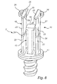
- the plunger 6 comprises a rod connector 7 for connecting with a front end portion 8 of the plunger rod 5, and a front plunger portion 7a, which is connected with the rod connector 7, and which is configured to seal the container 27 and to contact the liquid therein.
- the rod connector 7 and the front plunger portion 7a are separately manufactured and fitted together with a screw joint at an appropriate occasion.
- the rod connector 7 has an entrance opening 9 defined by wall sections 10 of the rod connector 7.
- the width of the entrance opening 9 is smaller than the width of the front end portion 8, and the width of a rod portion 11 adjacent to and rear of the front end portion 8 is at most the same as, and preferably smaller than, the width of the entrance opening 9.
- the wall sections 10 are resilient for enabling the front end portion 8 to pass the entrance opening 9 upon exerting a large enough force on the wall sections 10.
- the rod connector 7 comprises a rod stop portion 12, wherein there is a longitudinal play between the front end portion 8 of the plunger rod 5 on one hand and the entrance opening 9 and the rod stop portion 12 on the other hand. In other words, the distance between the entrance opening 9 and the rod stop portion 12 exceeds the length of the front end portion 8. Thereby it is possible for the front end portion 8 to move back and forth between the entrance opening 9 and the rod stop portion 12 without moving the plunger 6.
- the rod connector 7 comprises a base portion 17, here a circular base plate, at a front end of the rod connector 7, and two wall sections 10, which are attached to the base portion 17 and extend rearwards thereof opposite to each other. Furthermore, the rod stop portion 12 is connected with the base portion 17 between the wall sections 10.
- the rod stop portion 12 comprises a centre pin protruding rearwards from the base portion 17 at a centre thereof and ending at a free end, where the rod stop portion 12 is anvi shaped, and is ended with a flat abutment surface 18.
- the front end portion 8 of the rod 5 is frustoconically shaped having its top at the front end of the plunger rod 5, and thus it is ended with a flat end surface19, which is arranged to abut against the abutment surface 18 in an injection position, as will be further explained below.
- the frustoconical shape facilitates passage of the entrance opening 9.
- Each wall section 10 is generally plate shaped and has an inner surface 20, an outer surface 21, a front wall portion 22, connected with the base portion 17, and a rear wall portion 23 connected with the front wall portion 22 via a flexible joint 24.
- the rear wall portion 23 comprises a heel portion 25 extending radially inwards from the inner surface 20 at a rear end of the rear wall portion 23, at said entrance opening 9, and a resilient portion 26 protruding from the outer surface 21.
- each resilient portion 26 is constituted by an arc shaped tongue attached at its one end at the outer surface 21, and extends circumferentially and alongside of the heel portion 25 at a small distance from the outer surface 21.
- the front end portion 8 of the plunger rod 5 comprises a circumferential engagement surface 28 at a rear end of the front end portion 8, the engagement surface 28 being arranged to engage with the plunger 6, at the entrance opening 9, for moving the plunger 6 rearwards.
- Each heel portion 25 comprises a complementary engagement surface 29 for engagement with the engagement surface 28 of the plunger rod 8, at the entrance opening 9.
- the complementary engagement surface 29 has an inclined surface leaning inwards, i.e. towards the longitudinal centre of the rod connector 7, in a rearward direction.
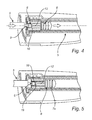
- the injection device 1 is operated as follows. After having inserted a cartridge 3 into the housing 2, the plunger 6 is in its rearmost position, and the plunger rod 5 is positioned at the rear of the plunger 6, as shown in Fig. 2 . Then the drive device 4 is activated by means of the operation button 16 for forwards operation, the plunger rod 5 is driven forward, and the front end portion 8 of the plunger rod 5 is entered into the rod connector 7 passed the entrance opening 9, by pushing the wall sections 10 aside, as shown in Fig. 3 . More particularly, each wall section 10 is bent at the flexible joint 24, such that the rear wall portion 23 is inclined outwards. During this entrance, the resilient portions 26 are compressed, i.e.
- the entrance force needed will have to smaller than the resistance caused by the viscosity of the liquid and the friction against the wall of the container 27.
- some kind of additional mechanical hindrance can be provided, such as the circumferential rib (356) shown in WO0032259 .
- the plunger rod 5 At further forward movement of the plunger rod 5, its end surface 19 abuts against the abutment surface 18 of the rod stop portion 12, and the plunger rod 5 starts pushing the plunger 6 forward, thereby ejecting the liquid through the needle 14, as shown in Fig. 4 .
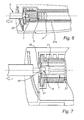
- the injection device 1 is arranged, i.e. its drive unit 4 is programmed, to reverse the plunger rod a small distance, as shown in Fig. 5 .
- This distance is to be just enough to cause a small gap between the end surface 19 of the front end portion 8 and the abutment surface 18 of the rod stop portion 12.
- the operation button 16 is operated for rearward operation, causing the plunger rod 5 to be retracted, as shown in Fig. 6 .
- the plunger 6 is pulled rearwards until it reaches the rear end of the container 27, and the cartridge 3.
- the rod connector 7 is stopped, but the plunger rod 5 continues rearwardly, while the engagement surface 28 slides across the inclined surfaces of the complementary engagement surfaces 29. This causes the rear wall portions 23 to bend outwards and let the front end portion 8 pass the entrance opening 9 and leave the rod connector 7. Then it is possible to remove the used cartridge 3.
- the shape of the front end portion 8 and its surfaces, in conjunction with the complementary engagement surfaces also contribute to enhance the entrance of the front end portion 8 into the rod connector 7, and to prevent non-intentional withdrawal of the front end portion 8 from the rod connector 7 at reversal of the plunger rod 5.
- the flexible joints add an amount of bending stress, forming a total counter force in conjunction with the resilient portions 26. However, at least in the illustrated embodiment the bending stress is negligible relative to the spring force of the resilient portions 26.
- the plunger rod can be driven in alternative ways, such as to give it a reciprocating movement, by means of an appropriate transmission of the rotational movement generated by the drive device to a longitudinal movement. It is, however, appreciated that the rotational transmission described above is more intuitive and has a simpler construction.
- the cartridge constitute the whole front part of the injection device.
Priority Applications (13)
| Application Number | Priority Date | Filing Date | Title |
|---|---|---|---|
| EP13199097.0A EP2886145A1 (en) | 2013-12-20 | 2013-12-20 | An injection device |
| PCT/EP2014/074183 WO2015090731A1 (en) | 2013-12-20 | 2014-11-10 | An injection device |
| RU2016126283A RU2016126283A (ru) | 2013-12-20 | 2014-11-10 | Инъекционное устройство |
| AU2014365598A AU2014365598A1 (en) | 2013-12-20 | 2014-11-10 | An injection device |
| EP14801964.9A EP3082908B1 (en) | 2013-12-20 | 2014-11-10 | An injection device |
| KR1020167019046A KR20160107191A (ko) | 2013-12-20 | 2014-11-10 | 주사 기구 |
| CN201480068137.9A CN105960252A (zh) | 2013-12-20 | 2014-11-10 | 注射设备 |
| MX2016007723A MX2016007723A (es) | 2013-12-20 | 2014-11-10 | Dispositivo de inyeccion. |
| US15/104,436 US10532159B2 (en) | 2013-12-20 | 2014-11-10 | Injection device |
| JP2016539270A JP2016540586A (ja) | 2013-12-20 | 2014-11-10 | 注射装置 |
| ES14801964T ES2719797T3 (es) | 2013-12-20 | 2014-11-10 | Un dispositivo de inyección |
| BR112016014548A BR112016014548A2 (pt) | 2013-12-20 | 2014-11-10 | Um dispositivo de injeção |
| CA2932391A CA2932391A1 (en) | 2013-12-20 | 2014-11-10 | An injection device |
Applications Claiming Priority (1)
| Application Number | Priority Date | Filing Date | Title |
|---|---|---|---|
| EP13199097.0A EP2886145A1 (en) | 2013-12-20 | 2013-12-20 | An injection device |
Publications (1)
| Publication Number | Publication Date |
|---|---|
| EP2886145A1 true EP2886145A1 (en) | 2015-06-24 |
Family
ID=49880558
Family Applications (2)
| Application Number | Title | Priority Date | Filing Date |
|---|---|---|---|
| EP13199097.0A Withdrawn EP2886145A1 (en) | 2013-12-20 | 2013-12-20 | An injection device |
| EP14801964.9A Active EP3082908B1 (en) | 2013-12-20 | 2014-11-10 | An injection device |
Family Applications After (1)
| Application Number | Title | Priority Date | Filing Date |
|---|---|---|---|
| EP14801964.9A Active EP3082908B1 (en) | 2013-12-20 | 2014-11-10 | An injection device |
Country Status (12)
| Country | Link |
|---|---|
| US (1) | US10532159B2 (ko) |
| EP (2) | EP2886145A1 (ko) |
| JP (1) | JP2016540586A (ko) |
| KR (1) | KR20160107191A (ko) |
| CN (1) | CN105960252A (ko) |
| AU (1) | AU2014365598A1 (ko) |
| BR (1) | BR112016014548A2 (ko) |
| CA (1) | CA2932391A1 (ko) |
| ES (1) | ES2719797T3 (ko) |
| MX (1) | MX2016007723A (ko) |
| RU (1) | RU2016126283A (ko) |
| WO (1) | WO2015090731A1 (ko) |
Families Citing this family (10)
| Publication number | Priority date | Publication date | Assignee | Title |
|---|---|---|---|---|
| ATE480278T1 (de) | 2005-09-12 | 2010-09-15 | Unomedical As | Einfürungssystem für ein infusionsset mit einem ersten und zweiten federeinheit |
| EP2552513B1 (en) | 2010-03-30 | 2014-03-19 | Unomedical A/S | Medical device |
| US10194938B2 (en) | 2011-03-14 | 2019-02-05 | UnoMedical, AS | Inserter system with transport protection |
| CN103957962B (zh) | 2011-10-05 | 2017-07-07 | 犹诺医药有限公司 | 用于同时插入多个经皮部分的插入物 |
| EP2583715A1 (en) | 2011-10-19 | 2013-04-24 | Unomedical A/S | Infusion tube system and method for manufacture |
| WO2017125817A1 (en) | 2016-01-19 | 2017-07-27 | Unomedical A/S | Cannula and infusion devices |
| EP3501574A1 (en) * | 2017-12-21 | 2019-06-26 | Q-Med AB | An exchangeable cartridge for an injection device |
| EP3598990A1 (en) * | 2018-07-23 | 2020-01-29 | Sanofi | Drug delivery device and assembly method for a drug delivery device |
| US11458292B2 (en) | 2019-05-20 | 2022-10-04 | Unomedical A/S | Rotatable infusion device and methods thereof |
| GB2590635B (en) * | 2019-12-20 | 2022-08-17 | Owen Mumford Ltd | Gap creation device |
Citations (7)
| Publication number | Priority date | Publication date | Assignee | Title |
|---|---|---|---|---|
| US5947935A (en) * | 1996-11-12 | 1999-09-07 | Medrad, Inc. | Syringes, syringe plungers and injector systems |
| WO2000032259A2 (en) | 1998-12-02 | 2000-06-08 | Saied V C | Apparatus for painless intramuscular or subcutaneous injections |
| WO2002004049A1 (en) * | 2000-07-10 | 2002-01-17 | Medrad, Inc. | Improvements relating to medical injector systems |
| US20050015056A1 (en) * | 2000-07-20 | 2005-01-20 | Douglas Duchon | Syringe plunger locking mechanism |
| US20090299328A1 (en) * | 2008-05-30 | 2009-12-03 | Allergan, Inc. | Injection device for soft-tissue augmentation fillers, bioactive agents and other biocompatible materials in liquid or gel form |
| EP2332602A1 (en) * | 2009-12-09 | 2011-06-15 | F. Hoffmann-La Roche AG | Container for receiving liquids |
| WO2013079643A1 (en) * | 2011-11-30 | 2013-06-06 | Sanofi-Aventis Deutschland Gmbh | Medical device for delivering at least one fluid from a medical device |
Family Cites Families (8)
| Publication number | Priority date | Publication date | Assignee | Title |
|---|---|---|---|---|
| US4299238A (en) * | 1980-06-24 | 1981-11-10 | Baidwan Balinderjeet S | Vented piston and push-rod subassembly for use in a syringe barrel |
| EP0346950B2 (en) * | 1984-06-06 | 1997-09-10 | Medrad Incorporated | Angiographic syringe for use with an angiographic injector |
| US5201709A (en) * | 1989-06-16 | 1993-04-13 | Capra Nicholas G | Single use, self destructing disposable syringe |
| US5411488A (en) * | 1994-05-06 | 1995-05-02 | Sterling Winthrop Inc. | Pre-filled syringe and pre-filled cartridge having an improved plunger and plunger rod for reducing syringing force |
| TW552947U (en) * | 2002-02-08 | 2003-09-11 | Jian-Wei Jung | Injector with easy detachment of push rod after retraction |
| US7553294B2 (en) * | 2002-05-30 | 2009-06-30 | Medrad, Inc. | Syringe plunger sensing mechanism for a medical injector |
| US7519431B2 (en) * | 2005-04-11 | 2009-04-14 | Medtronic, Inc. | Shifting between electrode combinations in electrical stimulation device |
| US9333293B2 (en) * | 2007-05-09 | 2016-05-10 | Acist Medical Systems, Inc. | Injector device, method, and computer program product for detecting a vacuum within a syringe |
-
2013
- 2013-12-20 EP EP13199097.0A patent/EP2886145A1/en not_active Withdrawn
-
2014
- 2014-11-10 WO PCT/EP2014/074183 patent/WO2015090731A1/en active Application Filing
- 2014-11-10 JP JP2016539270A patent/JP2016540586A/ja active Pending
- 2014-11-10 BR BR112016014548A patent/BR112016014548A2/pt not_active Application Discontinuation
- 2014-11-10 CA CA2932391A patent/CA2932391A1/en not_active Abandoned
- 2014-11-10 AU AU2014365598A patent/AU2014365598A1/en not_active Abandoned
- 2014-11-10 RU RU2016126283A patent/RU2016126283A/ru unknown
- 2014-11-10 US US15/104,436 patent/US10532159B2/en not_active Expired - Fee Related
- 2014-11-10 ES ES14801964T patent/ES2719797T3/es active Active
- 2014-11-10 MX MX2016007723A patent/MX2016007723A/es unknown
- 2014-11-10 CN CN201480068137.9A patent/CN105960252A/zh active Pending
- 2014-11-10 EP EP14801964.9A patent/EP3082908B1/en active Active
- 2014-11-10 KR KR1020167019046A patent/KR20160107191A/ko not_active Application Discontinuation
Patent Citations (7)
| Publication number | Priority date | Publication date | Assignee | Title |
|---|---|---|---|---|
| US5947935A (en) * | 1996-11-12 | 1999-09-07 | Medrad, Inc. | Syringes, syringe plungers and injector systems |
| WO2000032259A2 (en) | 1998-12-02 | 2000-06-08 | Saied V C | Apparatus for painless intramuscular or subcutaneous injections |
| WO2002004049A1 (en) * | 2000-07-10 | 2002-01-17 | Medrad, Inc. | Improvements relating to medical injector systems |
| US20050015056A1 (en) * | 2000-07-20 | 2005-01-20 | Douglas Duchon | Syringe plunger locking mechanism |
| US20090299328A1 (en) * | 2008-05-30 | 2009-12-03 | Allergan, Inc. | Injection device for soft-tissue augmentation fillers, bioactive agents and other biocompatible materials in liquid or gel form |
| EP2332602A1 (en) * | 2009-12-09 | 2011-06-15 | F. Hoffmann-La Roche AG | Container for receiving liquids |
| WO2013079643A1 (en) * | 2011-11-30 | 2013-06-06 | Sanofi-Aventis Deutschland Gmbh | Medical device for delivering at least one fluid from a medical device |
Also Published As
| Publication number | Publication date |
|---|---|
| KR20160107191A (ko) | 2016-09-13 |
| EP3082908B1 (en) | 2019-03-06 |
| US20160310674A1 (en) | 2016-10-27 |
| BR112016014548A2 (pt) | 2017-08-08 |
| WO2015090731A1 (en) | 2015-06-25 |
| MX2016007723A (es) | 2016-09-09 |
| US10532159B2 (en) | 2020-01-14 |
| CA2932391A1 (en) | 2015-06-25 |
| CN105960252A (zh) | 2016-09-21 |
| EP3082908A1 (en) | 2016-10-26 |
| AU2014365598A1 (en) | 2016-07-07 |
| JP2016540586A (ja) | 2016-12-28 |
| RU2016126283A (ru) | 2018-01-25 |
| ES2719797T3 (es) | 2019-07-16 |
Similar Documents
| Publication | Publication Date | Title |
|---|---|---|
| EP3082908B1 (en) | An injection device | |
| CA2882229C (en) | Automatic injection device | |
| JP5000489B2 (ja) | 注入装置 | |
| RU2475278C2 (ru) | Одноразовое устройство для выталкивания жидкого или пастообразного продукта | |
| US20120016296A1 (en) | Autoinjector with mixing means | |
| JP4660549B2 (ja) | 順序制御機能を備える投薬量設定機構 | |
| JP6359774B2 (ja) | 投与量設定機構および投与量設定機構を含む薬剤送達装置 | |
| US20090054850A1 (en) | Pusher with a coupling element | |
| US6139526A (en) | Single use self disabling safety syringe | |
| EP3616738A1 (en) | Injection pen | |
| CN110691620A (zh) | 具有灌注布置的注射装置 | |
| KR101496048B1 (ko) | 매뉴얼 인젝터 | |
| US11839748B2 (en) | Plunging apparatus for syringe | |
| TWI662976B (zh) | 注射器的推進裝置 | |
| US11707575B2 (en) | Exchangeable cartridge for an injection device | |
| KR20210133245A (ko) | 다기능 바늘 홀더 및 리테이너 링 조립체를 가지는 주사기 | |
| JP2020516399A (ja) | プランジャ構成および収束傾斜面を有する注射器具 |
Legal Events
| Date | Code | Title | Description |
|---|---|---|---|
| PUAI | Public reference made under article 153(3) epc to a published international application that has entered the european phase |
Free format text: ORIGINAL CODE: 0009012 |
|
| 17P | Request for examination filed |
Effective date: 20131220 |
|
| AK | Designated contracting states |
Kind code of ref document: A1 Designated state(s): AL AT BE BG CH CY CZ DE DK EE ES FI FR GB GR HR HU IE IS IT LI LT LU LV MC MK MT NL NO PL PT RO RS SE SI SK SM TR |
|
| AX | Request for extension of the european patent |
Extension state: BA ME |
|
| R17P | Request for examination filed (corrected) |
Effective date: 20151221 |
|
| RBV | Designated contracting states (corrected) |
Designated state(s): AL AT BE BG CH CY CZ DE DK EE ES FI FR GB GR HR HU IE IS IT LI LT LU LV MC MK MT NL NO PL PT RO RS SE SI SK SM TR |
|
| 17Q | First examination report despatched |
Effective date: 20180813 |
|
| STAA | Information on the status of an ep patent application or granted ep patent |
Free format text: STATUS: THE APPLICATION IS DEEMED TO BE WITHDRAWN |
|
| 18D | Application deemed to be withdrawn |
Effective date: 20200701 |