EP2886027A1 - Wet wipe container with spray pump dispenser - Google Patents
Wet wipe container with spray pump dispenser Download PDFInfo
- Publication number
- EP2886027A1 EP2886027A1 EP14199173.7A EP14199173A EP2886027A1 EP 2886027 A1 EP2886027 A1 EP 2886027A1 EP 14199173 A EP14199173 A EP 14199173A EP 2886027 A1 EP2886027 A1 EP 2886027A1
- Authority
- EP
- European Patent Office
- Prior art keywords
- lid
- wet wipe
- wet
- wipe
- housing
- Prior art date
- Legal status (The legal status is an assumption and is not a legal conclusion. Google has not performed a legal analysis and makes no representation as to the accuracy of the status listed.)
- Granted
Links
- 239000007921 spray Substances 0.000 title claims abstract description 60
- 239000012530 fluid Substances 0.000 claims abstract description 48
- 230000007246 mechanism Effects 0.000 claims description 49
- 230000000994 depressogenic effect Effects 0.000 claims description 12
- 238000010792 warming Methods 0.000 claims description 6
- 230000000881 depressing effect Effects 0.000 claims description 4
- 238000000034 method Methods 0.000 claims description 4
- 238000009736 wetting Methods 0.000 claims description 2
- 230000003020 moisturizing effect Effects 0.000 abstract description 5
- 238000010438 heat treatment Methods 0.000 description 26
- 239000000463 material Substances 0.000 description 10
- 238000004891 communication Methods 0.000 description 4
- 238000010586 diagram Methods 0.000 description 4
- 239000007788 liquid Substances 0.000 description 4
- 239000012528 membrane Substances 0.000 description 3
- 239000004433 Thermoplastic polyurethane Substances 0.000 description 2
- 230000008901 benefit Effects 0.000 description 2
- 238000002845 discoloration Methods 0.000 description 2
- 238000001035 drying Methods 0.000 description 2
- 230000005611 electricity Effects 0.000 description 2
- 239000002184 metal Substances 0.000 description 2
- 229910052751 metal Inorganic materials 0.000 description 2
- 238000012986 modification Methods 0.000 description 2
- 230000004048 modification Effects 0.000 description 2
- 239000004033 plastic Substances 0.000 description 2
- 229920003023 plastic Polymers 0.000 description 2
- 229920000642 polymer Polymers 0.000 description 2
- 229920006124 polyolefin elastomer Polymers 0.000 description 2
- 230000008569 process Effects 0.000 description 2
- 229920002803 thermoplastic polyurethane Polymers 0.000 description 2
- 239000004909 Moisturizer Substances 0.000 description 1
- 230000009471 action Effects 0.000 description 1
- 239000000919 ceramic Substances 0.000 description 1
- 239000003086 colorant Substances 0.000 description 1
- 239000002131 composite material Substances 0.000 description 1
- 238000010276 construction Methods 0.000 description 1
- 238000007796 conventional method Methods 0.000 description 1
- 229920001971 elastomer Polymers 0.000 description 1
- 238000001704 evaporation Methods 0.000 description 1
- 230000008020 evaporation Effects 0.000 description 1
- 239000006210 lotion Substances 0.000 description 1
- 238000004519 manufacturing process Methods 0.000 description 1
- 150000002739 metals Chemical class 0.000 description 1
- 239000000203 mixture Substances 0.000 description 1
- 230000001333 moisturizer Effects 0.000 description 1
- 229920000728 polyester Polymers 0.000 description 1
- 239000003755 preservative agent Substances 0.000 description 1
- 230000037452 priming Effects 0.000 description 1
- 230000000717 retained effect Effects 0.000 description 1
- 238000005507 spraying Methods 0.000 description 1
- 229920001169 thermoplastic Polymers 0.000 description 1
- 239000004416 thermosoftening plastic Substances 0.000 description 1
Images


Classifications
-
- A—HUMAN NECESSITIES
- A47—FURNITURE; DOMESTIC ARTICLES OR APPLIANCES; COFFEE MILLS; SPICE MILLS; SUCTION CLEANERS IN GENERAL
- A47K—SANITARY EQUIPMENT NOT OTHERWISE PROVIDED FOR; TOILET ACCESSORIES
- A47K10/00—Body-drying implements; Toilet paper; Holders therefor
- A47K10/24—Towel dispensers, e.g. for piled-up or folded textile towels; Toilet-paper dispensers; Dispensers for piled-up or folded textile towels provided or not with devices for taking-up soiled towels as far as not mechanically driven
- A47K10/32—Dispensers for paper towels or toilet-paper
- A47K10/42—Dispensers for paper towels or toilet-paper dispensing from a store of single sheets, e.g. stacked
- A47K10/421—Dispensers for paper towels or toilet-paper dispensing from a store of single sheets, e.g. stacked dispensing from the top of the dispenser
-
- B—PERFORMING OPERATIONS; TRANSPORTING
- B65—CONVEYING; PACKING; STORING; HANDLING THIN OR FILAMENTARY MATERIAL
- B65D—CONTAINERS FOR STORAGE OR TRANSPORT OF ARTICLES OR MATERIALS, e.g. BAGS, BARRELS, BOTTLES, BOXES, CANS, CARTONS, CRATES, DRUMS, JARS, TANKS, HOPPERS, FORWARDING CONTAINERS; ACCESSORIES, CLOSURES, OR FITTINGS THEREFOR; PACKAGING ELEMENTS; PACKAGES
- B65D43/00—Lids or covers for rigid or semi-rigid containers
- B65D43/14—Non-removable lids or covers
- B65D43/16—Non-removable lids or covers hinged for upward or downward movement
-
- B—PERFORMING OPERATIONS; TRANSPORTING
- B65—CONVEYING; PACKING; STORING; HANDLING THIN OR FILAMENTARY MATERIAL
- B65D—CONTAINERS FOR STORAGE OR TRANSPORT OF ARTICLES OR MATERIALS, e.g. BAGS, BARRELS, BOTTLES, BOXES, CANS, CARTONS, CRATES, DRUMS, JARS, TANKS, HOPPERS, FORWARDING CONTAINERS; ACCESSORIES, CLOSURES, OR FITTINGS THEREFOR; PACKAGING ELEMENTS; PACKAGES
- B65D83/00—Containers or packages with special means for dispensing contents
- B65D83/08—Containers or packages with special means for dispensing contents for dispensing thin flat articles in succession
- B65D83/0805—Containers or packages with special means for dispensing contents for dispensing thin flat articles in succession through an aperture in a wall
-
- A—HUMAN NECESSITIES
- A47—FURNITURE; DOMESTIC ARTICLES OR APPLIANCES; COFFEE MILLS; SPICE MILLS; SUCTION CLEANERS IN GENERAL
- A47K—SANITARY EQUIPMENT NOT OTHERWISE PROVIDED FOR; TOILET ACCESSORIES
- A47K10/00—Body-drying implements; Toilet paper; Holders therefor
- A47K10/24—Towel dispensers, e.g. for piled-up or folded textile towels; Toilet-paper dispensers; Dispensers for piled-up or folded textile towels provided or not with devices for taking-up soiled towels as far as not mechanically driven
- A47K10/32—Dispensers for paper towels or toilet-paper
- A47K2010/3266—Wet wipes
- A47K2010/3273—Wet wipes moistened just before use
- A47K2010/328—Wet wipes moistened just before use by spraying
-
- A—HUMAN NECESSITIES
- A47—FURNITURE; DOMESTIC ARTICLES OR APPLIANCES; COFFEE MILLS; SPICE MILLS; SUCTION CLEANERS IN GENERAL
- A47K—SANITARY EQUIPMENT NOT OTHERWISE PROVIDED FOR; TOILET ACCESSORIES
- A47K10/00—Body-drying implements; Toilet paper; Holders therefor
- A47K10/24—Towel dispensers, e.g. for piled-up or folded textile towels; Toilet-paper dispensers; Dispensers for piled-up or folded textile towels provided or not with devices for taking-up soiled towels as far as not mechanically driven
- A47K10/32—Dispensers for paper towels or toilet-paper
- A47K2010/3266—Wet wipes
- A47K2010/3293—Wet wipes combined with wipe warming devices
Definitions
- the subject disclosure relates to baby wipe warmers, and in particular to a baby wipe warmer having a fluid pump dispenser adapted to provide moisture to the wipes for maintaining moisture and to prevent discoloration of the wipes.
- Conventional baby wipe warmers store small pre-moistened paper or synthetic (non-woven) towelettes within a wipe warmer housing.
- the wipes are primarily used to cleanse and/or moisturize the skin of infants, small children and the like.
- Various moisteners such as cleansers, lotions and preservatives are supplied to moisten the wipes after a towelette has been removed from its container.
- Numerous warming devices are available to provide warmth to the wipe to comfort the infant instead of applying a cold wet wipe to the skin of the infant.
- FIGS. 1-6 show a first configuration for a wet wipe container 10.
- the wet wipe container 10 is adapted to warm and/or moisturize a stack of wipes 13 within a housing 11.
- the wet wipe container 10 may comprise a housing 11, a lid 12, a wipe access door 14 and a spray pump mechanism 20. It is to be understood that the wet wipe container 10 may be formed to have a variety of housing shapes, configurations, geometries, sizes and textures in addition to that shown in the provided in the figures.
- FIG. 2 depicts an exploded view of the wet wipe container 10.
- the wet wipe container 10 may be fabricated from any rigid material, such as a plastic polymer, a metal and/or any other suitable material composition.
- the housing 11 is constructed to have a lower closed end and an open upper end with the lid 12 pivotally attached to cover the open upper end.
- the container housing 11 is formed of a main body member 50, a base member 54 and the lid 12.
- the body member 50 is peripherally formed by various exterior-side housing walls, e.g., a front wall 51 a, a rear wall 51 b, a first side wall 51 c, a second side wall 51 d and a base wall 51 e.
- a lower base end 52 of the various external housing walls 51 a-51 d are attached to the base wall 51 e.
- the shape of the wet wipe container 10 may be contoured to take various shapes. As shown in the figures, the body member 50 may have smooth curved sides and edges.
- the base member 54 supports the wet wipe container 10 on a surface (e.g., a desktop, a floor, a night stand, etc.).
- a pad or plurality of adjustable foot pads may be adapted for use on a lower surface of the base member 54.
- the housing 11 defines an inside compartment 16 to hold the stack of wipes 13.
- the shape of the inside compartment 16 may be substantially similar to the shape of the stack of wipes 13.
- a spray pump recess 70 may be integrated into one of the walls of the housing 11.
- the spray pump recess 70 is adapted to receive and secure the spray pump mechanism 20 for wetting and/or providing a moisturizer directly onto the stack of wipes 13 while the stack of wipes 13 are contained in their storage position within the inside compartment 16 of the housing 11.
- the spray pump mechanism 20 may be located outside of the housing 11 with an outlet for providing moisture directly onto the stack of wipes 13, as will be described in greater detail below.
- An inner front wall 16a is provided slightly inset from the front wall 51 a.
- the inner front wall 16a being a part of the internal wipe housing compartment 16 separates the stack of wipes 13 from the spray pump mechanism 20.
- the spray pump mechanism 20 may also be located in the housing 11 at any location which would allow for the spraying of the stack of wipes 13. That is, the spray pump mechanism 20 can also be located in any of the side walls of the wipe compartment 16, lid 12, base wall 51 e, or externally adjacent to the housing 11.
- the recess 70 may include a number of alignment features to facilitate positioning and securing of the spray pump mechanism 20.
- the recess 70 may have tracks 72 which may be recessed to slidingly receive protruding outer edges 77 of the spray pump mechanism 20.
- the recess 70 may also include a lower lip 73 which retains a bottom surface 78 of the spray pump mechanism 20, preventing it from laterally moving relative to the housing 11.
- the front wall 16a of the inner compartment 16 may also include an inwardly recessed portion 74, upon which rests an outwardly projecting ledge 79 on the spray pump mechanism 20.
- the tracks 72, the lower lip 73, and recessed portion 74, as well as a concave surface 71 of the recess 70 and complimentary convex surface 76 on the spray pump mechanism 20 all facilitate the aligning of the mechanism 20 as it is slides into secure positioning within the housing 11.
- An advantage of having the spray pump mechanism 20 securely positioned and held within the housing 11 is to allow a user to spray a fluid in the spray pump mechanism 20 directly onto the stack of wipes 13 while the lid 12 is in a closed position, as will be discussed in greater detail below.
- the wet wipe container 10 includes the pivotally engaged top lid 12.
- the lid 12 is capable of opening and closing relative to the housing 11 in order to access the wipes 13 within the internal wipe housing compartment 16 within the housing 11 and to load a new stack of wipes 13.
- the lid 12 may pivot about a hinge 53 in the exterior-side housing wall 51 and rotate between an open and closed position.
- a first securing mechanism such as latching protrusions (not shown) extending from an underside of the lid member 12 which snap-fit into receiving grooves 80 provided on an upper side of the front wall 51 a in the housing 11.
- the lid member 12 may open and close utilizing any conventional method such as using a door spring, for example.
- the lid member 12 may include a resilient lid seal 106.
- the material used may be a plastic polymer, rubber, etc. and/or any other suitable material to form an air-tight seal.
- the lid seal 106 rests against the upper edges of the inside compartment 16 such that the lid seal 106 is slightly deformed to prevent fluid communication of air and/or moisture from the inside compartment 16 and the environment. This helps prevent the stack of wipes 13 from drying or browning.
- the lid seal 106 may also rest abuttingly against the spray pump mechanism 20, such that the outlet 28 is held within the air-tight seal and in fluid communication with the inside compartment 16. In this way, the outlet 28 may spray fluid from the spray pump mechanism 20 directly onto the stack of wipes 13 while the inside compartment 16 remains sealed from the outside environment.
- the resilient lid seal 106 may be over-molded onto the lid 12 with various materials which, for example, may include thermoplastic polyurethane (TPU) or thermoplastic polyesters (TPE), polyolefin Elastomers (POE).
- TPU thermoplastic polyurethane
- TPE thermoplastic polyesters
- POE polyolefin Elastomers
- Other commercially available materials may include Engage, Sarlink, Texin, Desmopan, Dynaflex, Versalloy, Versaflex and Elastolan. It should be noted that some or all of the above commercially available materials may be trademarks of the companies' manufacturing and/or selling the materials.
- FIG. 3 shows the lid member 12 in a closed position.
- the lid member 12 When the lid member 12 is closed, it partially becomes an upper housing wall as it partially encloses the open end of the internal wipe housing compartment 16 in the interior of the housing 11 from the outside. Opening the lid member 12 allows access to the inside compartment 16 of the housing 11 to refill a stack of wipes 13 (layered or inter-folded stack) to be individually withdrawn for use through a wipes access opening or dispensing opening 15 provided below a dispensing lid or wipes access door 14, as shown in FIG. 4 .
- FIG. 4 illustrates the wipe access door 14 in an open position.
- the wipes access door 14 pivots open about the lid 12.
- the wipes access door 14 pivots independently about a separate access door hinge 86 relative to the hinge 53 of the lid 12.
- a user can access a wipe 13 and pull it through the wipe access opening 15 provided below the wipes access door 14.
- the wipes access door 14 is secured closed by a second securing mechanism, such as a second latch 19 as shown in FIG. 5 .
- the first or second securing mechanisms may be configured as a releasable connection, such as with a releasably locking push-button latch 82, a snap lock, a latching mechanism, or the like.
- the lid 12 and the wipe access door 14 may also include a resilient wipe access door seal 102 and corresponding abutment surface 104 which projects away from the wipe access door 14.
- the resilient wipe access door seal 102 may be over-molded in a similar fashion to the resilient lid seal 106.
- the resilient wipe access door seal 102 may be in the form of a ring surrounding the wipe access opening 15, which engages the abutment surface 104 when the wipe access door is in a closed position in order to prevent fluid communication of air between the inside compartment 16 and the outside environment.
- the abutment surface 104 slightly deforms the resilient wipe access door seal 102 to form an air-tight boundary.
- the resilient wipe access door seal 102 and abutment surface 104 may be formed in a variety of shapes or sizes suitable to create the air-tight connection. Furthermore, the resilient wipe access door seal 102 may be made from various materials, including those listed above for the resilient lid seal 106.
- the wipe access door 14 may be provided with a resilient biasing mechanism for biasing the door 14 into the open position.
- the resilient biasing mechanism may be a hinge spring 84.
- the hinge spring 84 may be constructed as a flexible, resilient member that bends and/or deflects as the wipe access door 14 moves into a closed position.
- the hinge spring 84 may also be a torsion spring located at an access door hinge 86, or any other suitable biasing mechanism for opening the wipe access door 14 when the push-button latch 82 releases the second latch 19.
- An LED light or indicator 90 may be provided to indicate when the heating element 30 is powered, as shown and described in more detail in FIG. 32 .
- the light 90 may be any suitable light source and may be located in the housing 11, the lid 12, the wipe access door 14, or any other location within the wet wipe container 10.
- the light 90 may also oscillate on and off at various frequencies to represent different temperature statuses, such as to blink when the wet wipe container 10 has reached a predetermined temperature or the like.
- the light 90 may alternate between various different colors to indicate various stages of the warming process.
- FIGS. 5-6 depict a cross-section view of the wet wipe container 10.
- An intermediate push-button 40 may be provided within the lid 12. When the wipe access door 14 is in the open position, a user may press the intermediate push-button 40 which in turn will depress the push-button 24 on the spray pump mechanism 20 and spray fluid into the internal compartment 16. Furthermore, an extending lug 25 may protrude from the wipe access door 14 which will depress the intermediate push-button 40 when the wipe access door 14 is moved into a closed position. Multiple mechanisms by which a user may depress the push-button 24 on the spray pump mechanism 20 are discussed at greater length below.
- the push-button 24 may also include projection or alignment tabs 24a (as shown in FIG. 2 and 7 ) to keep the outlet 28 pointed in the direction of the stack of wipes 13 as it is dispersed.
- a heating element 30 is provided within the wet wipe container 10.
- the heating element 30 is provided within the housing to heat the contents within the wet wipe container 10. That is, the heating element 30 may be provided to warm an internal fluid compartment 22 in the spray pump mechanism 20 and the internal wipes compartment 16.
- the heating element 30 may be disposed in the lid 12, the housing 11, the internal compartment 16 or in various positions in the wet wipe container 10 to achieve its warming purpose.
- An advantage to disposing the heating element 30 above the stack of wipes 13 is to keep the top wipe, the next wipe to be used, warm.
- a heater selected from various commercially available heating elements may be used to generate and provide heating to the various elements within the wet wipe container 10.
- the heating element 30 may also be electronically integrated with the LED light 90 and/or a display (not shown) in order to provide the user with information regarding the temperature and status of the heating element 30.
- the spray pump mechanism 20 is integrated into the housing 11 of the wet wipe container 10.
- the spray pump mechanism 20 includes the internal liquid compartment 22 capable of holding a fluid 23.
- the compartment 22 may be separated from the internal wipe housing compartment 16.
- the spray pump mechanism 20 is operable to draw the fluid 23 from the internal liquid compartment 22 for delivery of the moisturizing fluid to the wipes 13 stored in the wipe housing compartment 16.
- the compartment 22 may be disposed outside of the housing 11 such that the fluid 23 is drawn through the outlet 28 and delivered directly to the wipes 13 stored within the compartment 16.
- a push-button 24 of the spray pump mechanism can be provided in a variety of different configurations as will be described with respect to FIGS. 5-6 and 17-19 .
- the spray pump mechanism 20 may be electronically or mechanically actuated.
- the push-button 24, as depicted in FIGS. 1 and 5-6 , may be actuated in a variety of different ways. As shown in FIG. 1 , the push-button 24 is exposed when the lid 12 is in the open position and may be depressed manually by the user to spray the fluid 23 onto the stack of wipes 13. As shown in FIG. 4 , the user may press the intermediate push-button 40 to actuate the push-button 24. In addition, as shown in FIG. 6 , the extending lug 25 of the wipe access door 14 may depress the intermediate push-button 40 which in turn actuates the push-button 24.
- the extending lug 25 presses against the intermediate push-button 40, which presses against the push-button 24 thereby drawing fluid 23 from the fluid compartment 22 into a fluid channel 26 in the push-button 24 and dispersing a moistening spray 27 from an outlet nozzle 28 in the head of the push-button 24.
- the spray pump mechanism 20 can be constructed to dispense a moistening spray 27, when the depressed push-button 24 is released from its depressed position.
- the outlet nozzle 28 disposed in the push-button 24 of the spray pump mechanism 20 is configured to project the fluid spray 27 directly into the housing compartment 16 of wet wipe container 10.
- the fluid spray 27 sprays directly onto and to completely cover the exposed portions of the wipes within the housing compartment 16 when the lid is in a closed position or an open position.
- dispersing the moisturized fluid 27 onto the wipes assures receipt of a moist and warm wipe 13a when pulled from within the wet wipe warmer 10.
- the moisturized fluid 27 serves to provide sufficient moisture to the wipes 13 to overcome the drying out of the wet wipes 13 as a result of liquid evaporation during the heating of the various wipes 13.
- FIG. 6 also depicts the hinge spring 84 in a deflected position between the wipe access door 14 and lid 12. This configuration provides the hinge spring 84 with the necessary torsion force to bias the wipe access door 14 open when the latch mechanism 19 is released by the push-button latch 82.
- the wipe access opening 15 may be constructed as a thin flexible membrane 57 having a narrow slit 58.
- the user when pulling a new wipe 13a from the stack of wipes 13 and priming the wet wipe container 10, the user may place their fingers through the narrow slit 58, slightly deflecting the thin flexible membrane 57, in order to retrieve the wipe 13a.
- the wipe 13a When the wipe 13a is primed with fluid 23, it may be secured and retained within the thin flexible membrane 57 by the narrow slit 58 as shown in FIG. 6 .
- the heating element 30 is powered and providing heat to the internal compartment 16 and the stack of wipes 13, the wipe 13a may be positioned between the heating elements 30 as shown in FIG. 5 .
- FIG. 7 shows an exploded view of the spray pump mechanism 20.
- the spray pump mechanism 20 may have a descending tube 29 having an inlet 29a.
- the bottom surface 78 of the housing of the spray pump mechanism 20 may be concave such that as the fluid 23 is drained from the internal compartment 22, the fluid 23 will pool at a lowest point 78a at a center of the internal compartment 22.
- the inlet 29a which draws in the fluid 23 into the internal fluid channel 26 may be in constant fluid communication with the fluid 23 until the internal compartment 22 is completely empty.
- FIGS. 8-18 show another configuration for a wet wipe container 10.
- the push-button 24 is shown actuated in a variety of different ways.
- the push-button 24 may be actuated by an extending lug 25 projecting from beneath the wipe access door 14.
- the extending lug 25 presses against the push-button 24 thereby drawing fluid 23 from the fluid compartment 22 into a fluid channel 26 in the push-button and dispersing a moistening spray 27 from an outlet nozzle 28 in the head of the push-button 24.
- the second latch 19 of the wipe access door 14 may be constructed as an integrated one-piece member of the extending lug 25.
- the fluid 23 may also be dispensed when the wipe access door 14 is open.
- a user may wish to spray the moisturizing fluid 23 onto the wipe 13a when the lid 12 is opened by depressing the head of the push-button 24 during the lid12 opening action.
- the fluid 23 in the fluid compartment 22 may also be dispensed when the lid 12 is open. That is, the user may spray the moisturizing fluid 23 onto the wipe by depressing the head of the push-button 24 thereby dispensing the fluid spray 27 onto the wipes 13.
- FIG. 9 shows an alternative position for the heating element 30.
- the heating element 30 may be located in a rear cavity 34 between the housing 11 and the inner wipe compartment 16 in order to heat the stack of wipes 13.
- the heating element 30 may also be located in a front cavity 36 located between the housing 11 and the inner wipe compartment 16, below the spray pump mechanism 20. In this configuration, the heating element 30 may be adjacent to both the stack of wipes 13 and the fluid 23 within the internal compartment 22 and may be provided to warm the internal fluid compartment 22 and the internal wipes compartment 16.
- FIG. 19 illustrates another exemplary embodiment in which the push-button 24 extends through the top of the lid 12 of the wet wipe container 10.
- the head of the push-button 24 may be accessed at any time whether the lid or the wipes access door 14 is open or closed as they do not interfere with access to the push-button 24.
- the fluid spray 27 through the push-button 24 is activated each time the elongated push-button 24 is directly depressed by a user.
- the second latch 19 may be disposed between the push-button 24 and the wipe access door 14.
- FIG. 20 depicts yet another exemplary embodiment in which the push-button 24 is also disposed below a second push-button 124 provided in the lid 12.
- the first push-button 24 is also depressed and the fluid spray 27 is dispersed over the wipes 13 in the housing compartment 16.
- the second push-button 124 may be actuated when the lid and the wipes access door 14 is in a closed position.
- the head of the push-button 24 may be directly or indirectly depressed to dispense the liquid fluid 27 onto the various wipes 13.
- FIGS. 21-31 depict another exemplary configuration for the wet wipe container housing as previously illustrated and described in FIGS. 19-20 .
- FIGS. 21-25 show various views of the lid 12 closed and the wipe access door 14 opened so that the wipes 13 may be accessed through the wipe access opening 15.
- FIGS. 26 -31 show various views of the lid 12 and wipe access door 14 closed and the combined second latch 19 and second push-button 124. As shown, the second push-button 124 is accessible and may be depressed so that the fluid spray 27 may be dispersed over the wipes 13 in the housing compartment 16 while the lid 12 and wipe access door 14 closed.
- FIG. 32 illustrates a schematic diagram of the heating elements 30.
- the schematic diagram is shown for exemplary purposes. It is to be understood that other suitable configurations may be used in accordance with this subject disclosure.
- a power source 42 may supply electricity to the heating elements 30, which radiates heat from the electricity passing through resistive material such as suitable metals, ceramics, composites, or other combinations. Power source 42 can be alternating current (AC) or direct current (DC) driven.
- AC alternating current
- DC direct current
- a switch 46 may be provided to actuate the heating elements 30.
- the switch 46 may be located on the wipe access door 14, the lid 12, the housing 11 or any other suitable location on the wet wipe container 10, at any location within the schematic diagram for altering the current flowing through the heating elements 30.
- FIG. 32 shows the heating elements 30 disposed within the lid 12, around the wipe access opening 15.
- the switch 46 may be a single button switch 46 which cycles though various stages of the warming process, or a multi-button panel 46 which may include a display (not shown) for displaying various information about the wet wipe container. Additionally, the heating elements 30 may be actuated upon plugging the wet wipe container 10 into the power source 42.
- the heating elements 30 may also be connected to the LED light or indicator 90.
- the LED light 90 may be provided to indicate when the heating element 30 is powered, or oscillate on and off at various frequencies to represent different temperature statuses.
- the LED light 90 may be integrated into the switch 46, such that the LED light 90 either protrudes from the switch 46 or may be seen through the switch 46.
- the wet wipe container 10 can be embodied in a variety of different sizes, shapes and configurations.
- the details and functionality of each of the various components are interchangeable and carry throughout the various embodiments.
- the illustrations and examples provided herein are for explanatory purposes and are not intended to limit the scope of the appended claims. It will be recognized by those skilled in the art that changes or modifications may be made to the above described embodiment without departing from the broad inventive concepts of the invention. It is understood therefore that the invention is not limited to the particular embodiment which is described, but is intended to cover all modifications and changes within the scope and spirit of the invention.
Abstract
Description
- This application claims priority to
U.S. Provisional Application Serial No. 61/918,621 filed December 19, 2013 - The subject disclosure relates to baby wipe warmers, and in particular to a baby wipe warmer having a fluid pump dispenser adapted to provide moisture to the wipes for maintaining moisture and to prevent discoloration of the wipes.
- Conventional baby wipe warmers store small pre-moistened paper or synthetic (non-woven) towelettes within a wipe warmer housing. The wipes are primarily used to cleanse and/or moisturize the skin of infants, small children and the like. Various moisteners, such as cleansers, lotions and preservatives are supplied to moisten the wipes after a towelette has been removed from its container. Numerous warming devices are available to provide warmth to the wipe to comfort the infant instead of applying a cold wet wipe to the skin of the infant.
- Many of these warming elements are electrically operated. However, adding the warmth to the wipe container inherently affects the intended use of the wipe warmer and the wipes contained therein, in that the heat causes the moisture in the wipes to evaporate. Heating the wipes also causes an undesirable discoloration to the wipe.
- Thus, there is a long-standing need to have a wipe warmer configured to effectively address these needs.
- Various exemplary embodiments of this disclosure will be described in detail, wherein like reference numerals refer to identical or similar components or steps, with reference to the following figures, wherein:
-
FIG. 1 illustrates an upper perspective view of an exemplary wet wipe container having a spray pump mechanism, a housing, a lid and a wipe access door according to the subject disclosure. -
FIG. 2 depicts an exploded view of the wet wipe container. -
FIG. 3 shows the wet wipe container having a wipe access door in a closed position. -
FIG. 4 illustrates the wet wipe container with the wipe access door in an open position. -
FIG. 5 is a cross section view about A-A inFIG. 4 showing a first embodiment for actuating the pump mechanism in the wet wipe container. -
FIG. 6 depicts a cross section view about B-B inFIG. 3 of the wet wipe container. -
FIG. 7 shows an exploded view of the spray pump mechanism. -
FIG. 8 illustrates an upper perspective view of another exemplary wet wipe container according to the subject disclosure. -
FIG. 9 is a cross section view about C-C inFIG. 9 showing a second embodiment for actuating the pump mechanism in the wet wipe container. -
FIG. 10 depicts a front view of a first configuration for the wet wipe container, having a lid in a closed position. -
FIG. 11 shows a rear perspective view of the wet wipe container. -
FIG. 12 illustrates a front view of the wet wipe container, having the lid in an open position. -
FIG. 13 depicts a rear view of the wet wipe container. -
FIG. 14 shows a side view of the wet wipe container, having the lid in the open position. -
FIG. 15 illustrates a rear perspective view of the wet wipe container. -
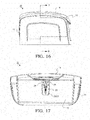
FIG. 16 depicts a side view of the wet wipe container, having the lid in the closed position. -
FIG. 17 shows a partial cross section view of the wet wipe container about cross section lines D-D inFIG. 16 . -
FIG. 18 illustrates an enlarged view of the pump mechanism provided in the wet wipe container. -
FIG. 19 depicts a third embodiment for actuating the pump mechanism in the wet wipe container. -
FIG. 20 shows a fourth embodiment for actuating the pump mechanism in the wet wipe container. -
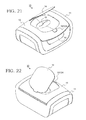
FIG. 21 depicts an upper perspective view of another configuration for the wet wipe container housing, having a wipe access door in an open position. -
FIG. 22 illustrates a rear perspective view of the wet wipe container. -
FIG. 23 shows a front view of the wet wipe container. -
FIG. 24 depicts a rear view of the wet wipe container. -
FIG. 25 illustrates a side view of the wet wipe container. -
FIG. 26 shows an upper perspective view of the wet wipe container, having the wipe access door in a closed position. -
FIG. 27 depicts a rear perspective view of the wet wipe container. -
FIG. 28 illustrates a front view of the wet wipe container. -
FIG. 29 shows a rear view of the wet wipe container. -
FIG. 30 depicts a side view of the wet wipe container. -
FIG. 31 illustrates a top view of the wet wipe container. -
FIG. 32 shows an exemplary schematic circuit diagram for the wet wipe container. - Particular embodiments of the present invention will now be described in greater detail with reference to the figures various, and not for purposes of limiting the same.
-
FIGS. 1-6 show a first configuration for awet wipe container 10. As shown, thewet wipe container 10 is adapted to warm and/or moisturize a stack ofwipes 13 within ahousing 11. Thewet wipe container 10 may comprise ahousing 11, alid 12, awipe access door 14 and aspray pump mechanism 20. It is to be understood that thewet wipe container 10 may be formed to have a variety of housing shapes, configurations, geometries, sizes and textures in addition to that shown in the provided in the figures. -
FIG. 2 depicts an exploded view of thewet wipe container 10. Thewet wipe container 10 may be fabricated from any rigid material, such as a plastic polymer, a metal and/or any other suitable material composition. - The
housing 11 is constructed to have a lower closed end and an open upper end with thelid 12 pivotally attached to cover the open upper end. Thecontainer housing 11 is formed of amain body member 50, abase member 54 and thelid 12. Thebody member 50 is peripherally formed by various exterior-side housing walls, e.g., afront wall 51 a, arear wall 51 b, afirst side wall 51 c, asecond side wall 51 d and abase wall 51 e. Alower base end 52 of the variousexternal housing walls 51 a-51 d are attached to thebase wall 51 e. The shape of thewet wipe container 10 may be contoured to take various shapes. As shown in the figures, thebody member 50 may have smooth curved sides and edges. - The
base member 54 supports thewet wipe container 10 on a surface (e.g., a desktop, a floor, a night stand, etc.). A pad or plurality of adjustable foot pads (as shown inFIGS. 5-6 ) may be adapted for use on a lower surface of thebase member 54. - The
housing 11 defines aninside compartment 16 to hold the stack ofwipes 13. The shape of theinside compartment 16 may be substantially similar to the shape of the stack ofwipes 13. - A
spray pump recess 70 may be integrated into one of the walls of thehousing 11. Thespray pump recess 70 is adapted to receive and secure thespray pump mechanism 20 for wetting and/or providing a moisturizer directly onto the stack ofwipes 13 while the stack ofwipes 13 are contained in their storage position within theinside compartment 16 of thehousing 11. Alternatively, thespray pump mechanism 20 may be located outside of thehousing 11 with an outlet for providing moisture directly onto the stack ofwipes 13, as will be described in greater detail below. - An inner
front wall 16a is provided slightly inset from thefront wall 51 a. The innerfront wall 16a being a part of the internal wipehousing compartment 16 separates the stack ofwipes 13 from thespray pump mechanism 20. It is to be understood that thespray pump mechanism 20 may also be located in thehousing 11 at any location which would allow for the spraying of the stack ofwipes 13. That is, thespray pump mechanism 20 can also be located in any of the side walls of the wipecompartment 16,lid 12,base wall 51 e, or externally adjacent to thehousing 11. - The
recess 70 may include a number of alignment features to facilitate positioning and securing of thespray pump mechanism 20. Therecess 70 may havetracks 72 which may be recessed to slidingly receive protrudingouter edges 77 of thespray pump mechanism 20. Therecess 70 may also include alower lip 73 which retains abottom surface 78 of thespray pump mechanism 20, preventing it from laterally moving relative to thehousing 11. Thefront wall 16a of theinner compartment 16 may also include an inwardly recessedportion 74, upon which rests an outwardly projectingledge 79 on thespray pump mechanism 20. Thetracks 72, thelower lip 73, and recessedportion 74, as well as aconcave surface 71 of therecess 70 and complimentaryconvex surface 76 on thespray pump mechanism 20 all facilitate the aligning of themechanism 20 as it is slides into secure positioning within thehousing 11. - An advantage of having the
spray pump mechanism 20 securely positioned and held within thehousing 11 is to allow a user to spray a fluid in thespray pump mechanism 20 directly onto the stack ofwipes 13 while thelid 12 is in a closed position, as will be discussed in greater detail below. - The wet wipe
container 10 includes the pivotally engagedtop lid 12. Thelid 12 is capable of opening and closing relative to thehousing 11 in order to access thewipes 13 within the internal wipehousing compartment 16 within thehousing 11 and to load a new stack ofwipes 13. Here, thelid 12 may pivot about ahinge 53 in the exterior-side housing wall 51 and rotate between an open and closed position. When in the closed position, thelid member 12 is held in place by a first securing mechanism, such as latching protrusions (not shown) extending from an underside of thelid member 12 which snap-fit into receivinggrooves 80 provided on an upper side of thefront wall 51 a in thehousing 11. Thelid member 12 may open and close utilizing any conventional method such as using a door spring, for example. - The
lid member 12 may include aresilient lid seal 106. The material used may be a plastic polymer, rubber, etc. and/or any other suitable material to form an air-tight seal. Thelid seal 106 rests against the upper edges of theinside compartment 16 such that thelid seal 106 is slightly deformed to prevent fluid communication of air and/or moisture from theinside compartment 16 and the environment. This helps prevent the stack ofwipes 13 from drying or browning. - As shown in
FIG. 6 , thelid seal 106 may also rest abuttingly against thespray pump mechanism 20, such that theoutlet 28 is held within the air-tight seal and in fluid communication with theinside compartment 16. In this way, theoutlet 28 may spray fluid from thespray pump mechanism 20 directly onto the stack ofwipes 13 while theinside compartment 16 remains sealed from the outside environment. - The
resilient lid seal 106 may be over-molded onto thelid 12 with various materials which, for example, may include thermoplastic polyurethane (TPU) or thermoplastic polyesters (TPE), polyolefin Elastomers (POE). Other commercially available materials may include Engage, Sarlink, Texin, Desmopan, Dynaflex, Versalloy, Versaflex and Elastolan. It should be noted that some or all of the above commercially available materials may be trademarks of the companies' manufacturing and/or selling the materials. -
FIG. 3 shows thelid member 12 in a closed position. When thelid member 12 is closed, it partially becomes an upper housing wall as it partially encloses the open end of the internal wipehousing compartment 16 in the interior of thehousing 11 from the outside. Opening thelid member 12 allows access to theinside compartment 16 of thehousing 11 to refill a stack of wipes 13 (layered or inter-folded stack) to be individually withdrawn for use through a wipes access opening or dispensingopening 15 provided below a dispensing lid or wipesaccess door 14, as shown inFIG. 4 . -
FIG. 4 illustrates the wipeaccess door 14 in an open position. The wipes accessdoor 14 pivots open about thelid 12. The wipes accessdoor 14 pivots independently about a separateaccess door hinge 86 relative to thehinge 53 of thelid 12. In an open position, a user can access a wipe 13 and pull it through the wipe access opening 15 provided below thewipes access door 14. The wipes accessdoor 14 is secured closed by a second securing mechanism, such as asecond latch 19 as shown inFIG. 5 . The first or second securing mechanisms may be configured as a releasable connection, such as with a releasably locking push-button latch 82, a snap lock, a latching mechanism, or the like. - The
lid 12 and the wipeaccess door 14 may also include a resilient wipeaccess door seal 102 andcorresponding abutment surface 104 which projects away from the wipeaccess door 14. The resilient wipeaccess door seal 102 may be over-molded in a similar fashion to theresilient lid seal 106. The resilient wipeaccess door seal 102 may be in the form of a ring surrounding the wipe access opening 15, which engages theabutment surface 104 when the wipe access door is in a closed position in order to prevent fluid communication of air between theinside compartment 16 and the outside environment. When the wipeaccess door 14 is closed, theabutment surface 104 slightly deforms the resilient wipeaccess door seal 102 to form an air-tight boundary. The resilient wipeaccess door seal 102 andabutment surface 104 may be formed in a variety of shapes or sizes suitable to create the air-tight connection. Furthermore, the resilient wipeaccess door seal 102 may be made from various materials, including those listed above for theresilient lid seal 106. - As shown in
FIG. 5 , the wipeaccess door 14 may be provided with a resilient biasing mechanism for biasing thedoor 14 into the open position. The resilient biasing mechanism may be ahinge spring 84. Thehinge spring 84 may be constructed as a flexible, resilient member that bends and/or deflects as the wipeaccess door 14 moves into a closed position. Thehinge spring 84 may also be a torsion spring located at anaccess door hinge 86, or any other suitable biasing mechanism for opening the wipeaccess door 14 when the push-button latch 82 releases thesecond latch 19. - An LED light or
indicator 90 may be provided to indicate when theheating element 30 is powered, as shown and described in more detail inFIG. 32 . The light 90 may be any suitable light source and may be located in thehousing 11, thelid 12, the wipeaccess door 14, or any other location within the wet wipecontainer 10. The light 90 may also oscillate on and off at various frequencies to represent different temperature statuses, such as to blink when the wet wipecontainer 10 has reached a predetermined temperature or the like. Likewise, the light 90 may alternate between various different colors to indicate various stages of the warming process. -
FIGS. 5-6 depict a cross-section view of the wet wipecontainer 10. An intermediate push-button 40 may be provided within thelid 12. When the wipeaccess door 14 is in the open position, a user may press the intermediate push-button 40 which in turn will depress the push-button 24 on thespray pump mechanism 20 and spray fluid into theinternal compartment 16. Furthermore, an extendinglug 25 may protrude from the wipeaccess door 14 which will depress the intermediate push-button 40 when the wipeaccess door 14 is moved into a closed position. Multiple mechanisms by which a user may depress the push-button 24 on thespray pump mechanism 20 are discussed at greater length below. The push-button 24 may also include projection oralignment tabs 24a (as shown inFIG. 2 and7 ) to keep theoutlet 28 pointed in the direction of the stack ofwipes 13 as it is dispersed. - A
heating element 30 is provided within the wet wipecontainer 10. Theheating element 30 is provided within the housing to heat the contents within the wet wipecontainer 10. That is, theheating element 30 may be provided to warm aninternal fluid compartment 22 in thespray pump mechanism 20 and theinternal wipes compartment 16. Theheating element 30 may be disposed in thelid 12, thehousing 11, theinternal compartment 16 or in various positions in the wet wipecontainer 10 to achieve its warming purpose. An advantage to disposing theheating element 30 above the stack ofwipes 13 is to keep the top wipe, the next wipe to be used, warm. - A heater selected from various commercially available heating elements may be used to generate and provide heating to the various elements within the wet wipe
container 10. Theheating element 30 may also be electronically integrated with theLED light 90 and/or a display (not shown) in order to provide the user with information regarding the temperature and status of theheating element 30. - The
spray pump mechanism 20 is integrated into thehousing 11 of the wet wipecontainer 10. Thespray pump mechanism 20 includes theinternal liquid compartment 22 capable of holding afluid 23. Thecompartment 22 may be separated from the internal wipehousing compartment 16. Thespray pump mechanism 20 is operable to draw the fluid 23 from theinternal liquid compartment 22 for delivery of the moisturizing fluid to thewipes 13 stored in the wipehousing compartment 16. In this manner, thecompartment 22 may be disposed outside of thehousing 11 such that the fluid 23 is drawn through theoutlet 28 and delivered directly to thewipes 13 stored within thecompartment 16. - As shown in detail in
FIGS. 5-6 , a push-button 24 of the spray pump mechanism can be provided in a variety of different configurations as will be described with respect toFIGS. 5-6 and17-19 . Thespray pump mechanism 20 may be electronically or mechanically actuated. - The push-
button 24, as depicted inFIGS. 1 and5-6 , may be actuated in a variety of different ways. As shown inFIG. 1 , the push-button 24 is exposed when thelid 12 is in the open position and may be depressed manually by the user to spray the fluid 23 onto the stack ofwipes 13. As shown inFIG. 4 , the user may press the intermediate push-button 40 to actuate the push-button 24. In addition, as shown inFIG. 6 , the extendinglug 25 of the wipeaccess door 14 may depress the intermediate push-button 40 which in turn actuates the push-button 24. - As shown in
FIG. 6 , when the wipeaccess door 14 is depressed, the extendinglug 25 presses against the intermediate push-button 40, which presses against the push-button 24 thereby drawingfluid 23 from thefluid compartment 22 into afluid channel 26 in the push-button 24 and dispersing a moisteningspray 27 from anoutlet nozzle 28 in the head of the push-button 24. When the wipeaccess door 14 is in a closed position, the push-button 24 will remain depressed until the wipeaccess door 14 is opened again. In an alternative configuration, thespray pump mechanism 20 can be constructed to dispense a moisteningspray 27, when the depressed push-button 24 is released from its depressed position. - The
outlet nozzle 28 disposed in the push-button 24 of thespray pump mechanism 20 is configured to project thefluid spray 27 directly into thehousing compartment 16 of wet wipecontainer 10. Thefluid spray 27 sprays directly onto and to completely cover the exposed portions of the wipes within thehousing compartment 16 when the lid is in a closed position or an open position. - In operation, dispersing the moisturized
fluid 27 onto the wipes assures receipt of a moist and warm wipe 13a when pulled from within the wet wipe warmer 10. The moisturizedfluid 27 serves to provide sufficient moisture to thewipes 13 to overcome the drying out of thewet wipes 13 as a result of liquid evaporation during the heating of the various wipes 13. -
FIG. 6 also depicts thehinge spring 84 in a deflected position between the wipeaccess door 14 andlid 12. This configuration provides thehinge spring 84 with the necessary torsion force to bias the wipeaccess door 14 open when thelatch mechanism 19 is released by the push-button latch 82. - In addition, the wipe access opening 15 may be constructed as a thin
flexible membrane 57 having anarrow slit 58. As shown inFIG. 4 , when pulling a new wipe 13a from the stack ofwipes 13 and priming the wet wipecontainer 10, the user may place their fingers through thenarrow slit 58, slightly deflecting the thinflexible membrane 57, in order to retrieve the wipe 13a. When the wipe 13a is primed withfluid 23, it may be secured and retained within the thinflexible membrane 57 by thenarrow slit 58 as shown inFIG. 6 . While theheating element 30 is powered and providing heat to theinternal compartment 16 and the stack ofwipes 13, the wipe 13a may be positioned between theheating elements 30 as shown inFIG. 5 . -
FIG. 7 shows an exploded view of thespray pump mechanism 20. Thespray pump mechanism 20 may have a descendingtube 29 having aninlet 29a. Thebottom surface 78 of the housing of thespray pump mechanism 20 may be concave such that as the fluid 23 is drained from theinternal compartment 22, the fluid 23 will pool at alowest point 78a at a center of theinternal compartment 22. In this configuration, theinlet 29a which draws in the fluid 23 into theinternal fluid channel 26 may be in constant fluid communication with the fluid 23 until theinternal compartment 22 is completely empty. -
FIGS. 8-18 show another configuration for a wet wipecontainer 10. In more detail inFIGS. 9 and17-18 , the push-button 24 is shown actuated in a variety of different ways. First, and as shown inFIG. 9 and18 , the push-button 24 may be actuated by an extendinglug 25 projecting from beneath the wipeaccess door 14. As shown inFIG. 9 , when the wipeaccess door 14 is depressed, the extendinglug 25 presses against the push-button 24 thereby drawingfluid 23 from thefluid compartment 22 into afluid channel 26 in the push-button and dispersing a moisteningspray 27 from anoutlet nozzle 28 in the head of the push-button 24. In addition, thesecond latch 19 of the wipeaccess door 14 may be constructed as an integrated one-piece member of the extendinglug 25. - The fluid 23 may also be dispensed when the wipe
access door 14 is open. A user may wish to spray the moisturizingfluid 23 onto the wipe 13a when thelid 12 is opened by depressing the head of the push-button 24 during the lid12 opening action. Similarly, the fluid 23 in thefluid compartment 22 may also be dispensed when thelid 12 is open. That is, the user may spray the moisturizingfluid 23 onto the wipe by depressing the head of the push-button 24 thereby dispensing thefluid spray 27 onto thewipes 13. -
FIG. 9 shows an alternative position for theheating element 30. Theheating element 30 may be located in arear cavity 34 between thehousing 11 and the inner wipecompartment 16 in order to heat the stack ofwipes 13. Theheating element 30 may also be located in afront cavity 36 located between thehousing 11 and the inner wipecompartment 16, below thespray pump mechanism 20. In this configuration, theheating element 30 may be adjacent to both the stack ofwipes 13 and the fluid 23 within theinternal compartment 22 and may be provided to warm theinternal fluid compartment 22 and theinternal wipes compartment 16. -
FIG. 19 illustrates another exemplary embodiment in which the push-button 24 extends through the top of thelid 12 of the wet wipecontainer 10. In this way, the head of the push-button 24 may be accessed at any time whether the lid or thewipes access door 14 is open or closed as they do not interfere with access to the push-button 24. Thefluid spray 27 through the push-button 24 is activated each time the elongated push-button 24 is directly depressed by a user. Furthermore, thesecond latch 19 may be disposed between the push-button 24 and the wipeaccess door 14. - Alternatively,
FIG. 20 depicts yet another exemplary embodiment in which the push-button 24 is also disposed below a second push-button 124 provided in thelid 12. In use, when the second push-button 124 is depressed, the first push-button 24 is also depressed and thefluid spray 27 is dispersed over thewipes 13 in thehousing compartment 16. The second push-button 124 may be actuated when the lid and thewipes access door 14 is in a closed position. One of ordinary skill in the art would understand that a variety of different constructions is possible in which the head of the push-button 24 may be directly or indirectly depressed to dispense theliquid fluid 27 onto the various wipes 13. -
FIGS. 21-31 depict another exemplary configuration for the wet wipe container housing as previously illustrated and described inFIGS. 19-20 . In particular,FIGS. 21-25 show various views of thelid 12 closed and the wipeaccess door 14 opened so that thewipes 13 may be accessed through the wipeaccess opening 15.FIGS. 26 -31 show various views of thelid 12 and wipeaccess door 14 closed and the combinedsecond latch 19 and second push-button 124. As shown, the second push-button 124 is accessible and may be depressed so that thefluid spray 27 may be dispersed over thewipes 13 in thehousing compartment 16 while thelid 12 and wipeaccess door 14 closed. -
FIG. 32 illustrates a schematic diagram of theheating elements 30. The schematic diagram is shown for exemplary purposes. It is to be understood that other suitable configurations may be used in accordance with this subject disclosure. Apower source 42 may supply electricity to theheating elements 30, which radiates heat from the electricity passing through resistive material such as suitable metals, ceramics, composites, or other combinations.Power source 42 can be alternating current (AC) or direct current (DC) driven. - A
switch 46 may be provided to actuate theheating elements 30. Theswitch 46 may be located on the wipeaccess door 14, thelid 12, thehousing 11 or any other suitable location on the wet wipecontainer 10, at any location within the schematic diagram for altering the current flowing through theheating elements 30.FIG. 32 shows theheating elements 30 disposed within thelid 12, around the wipeaccess opening 15. Theswitch 46 may be asingle button switch 46 which cycles though various stages of the warming process, or amulti-button panel 46 which may include a display (not shown) for displaying various information about the wet wipe container. Additionally, theheating elements 30 may be actuated upon plugging the wet wipecontainer 10 into thepower source 42. - The
heating elements 30 may also be connected to the LED light orindicator 90. As previously discussed, theLED light 90 may be provided to indicate when theheating element 30 is powered, or oscillate on and off at various frequencies to represent different temperature statuses. Furthermore, theLED light 90 may be integrated into theswitch 46, such that theLED light 90 either protrudes from theswitch 46 or may be seen through theswitch 46. - The wet wipe
container 10 can be embodied in a variety of different sizes, shapes and configurations. The details and functionality of each of the various components are interchangeable and carry throughout the various embodiments. The illustrations and examples provided herein are for explanatory purposes and are not intended to limit the scope of the appended claims. It will be recognized by those skilled in the art that changes or modifications may be made to the above described embodiment without departing from the broad inventive concepts of the invention. It is understood therefore that the invention is not limited to the particular embodiment which is described, but is intended to cover all modifications and changes within the scope and spirit of the invention.
Claims (20)
- A wet wipe container, the wet wipe container comprising:a wet wipe housing having an internal compartment for containing wet wipes;a lid connected to the housing; anda spray dispenser having an outlet positioned to dispense a fluid directly onto the wet wipes in a storage position in the housing.
- The wet wipe container recited in claim 1, wherein the wet wipes housing has an internal recess adapted to securely receive the spray dispenser.
- The wet wipe container recited in claim 2, wherein the internal recess of the wet wipes housing has at least one alignment feature for receiving and securing the spray dispenser.
- The wet wipe container recited in claim 1, further comprising a heater in the wet wipe housing or the lid to facilitate warming the wet wipes.
- The wet wipe container recited in claim 1, wherein the lid has a dispensing opening through which at least one wipe is dispensed and the dispensing system further comprises a dispensing lid.
- The wet wipe container recited in claim 5, wherein the spray dispenser has a push-button actuator for dispensing the fluid.
- The wet wipe container recited in claim 6, further comprising an intermediate push-button in contact with the push-button actuator, the intermediate push-button being accessible when the lid is in a closed position.
- The wet wipe container recited in claim 7, wherein the dispensing lid has an extending lug which depresses the intermediate push-button or spray dispenser when the dispensing lid is in a closed position.
- The wet wipe container recited in claim 7, wherein the intermediate push-button is accessible when the dispensing lid is in a closed position.
- The wet wipe container recited in claim 6, wherein the push-button actuator is accessible when the lid is in a closed position.
- The wet wipe container recited in claim 10, wherein the dispensing lid has an extending lug which depresses the push-button actuator when the dispensing lid is in a closed position.
- The wet wipe container recited in claim 10, wherein the push-button actuator is accessible when the dispensing lid is in a closed position.
- A wet wipe container system comprising:a wet wipe housing having an internal compartment for containing wet wipes;a lid connected to the wet wipe housing having a wipe access opening;a wipe access door adapted to cover the wipe access opening when in a closed position; anda spray pump mechanism having an actuator, and an outlet positioned to dispense a fluid directly onto the wet wipes while the lid is in a closed position.
- The wet wipe container system recited in claim 13, wherein the spray pump mechanism is secured within the wet wipe housing.
- The wet wipe container system recited in claim 13, wherein the actuator, either directly or indirectly, may be depressed while the lid is in the closed position.
- The wet wipe container system recited in claim 13, further comprising a first latch for securing the wipe access door in the closed position and a second latch for securing the lid to the wet wipe housing.
- The wet wipe container system recited in claim 16, wherein the wipe access door is biased towards an open position.
- The wet wipe container system recited in claim 16, wherein the first latch is a push-button latch.
- A method of wetting wipes, comprising:placing wet wipes within a container having an internal compartment, a lid connected to the container having a dispensing opening, and a dispensing lid adapted to cover the dispensing opening when in a closed position;providing a spray pump mechanism having a compartment for a fluid, an actuator, and an outlet positioned proximate to the wet wipes;depressing the actuator while the lid is being closed or in a closed position; anddispensing the fluid directly onto the wet wipes within the internal compartment.
- The method recited in claim 19, wherein when depressing the actuator, engaging an extending lug on the dispenser lid either direclty or indirectly to depress the actuator while the lid is in the closed position.
Applications Claiming Priority (2)
| Application Number | Priority Date | Filing Date | Title |
|---|---|---|---|
| US201361918621P | 2013-12-19 | 2013-12-19 | |
| US14/541,499 US10548438B2 (en) | 2013-12-19 | 2014-11-14 | Wet wipe container with spray pump dispenser |
Publications (2)
| Publication Number | Publication Date |
|---|---|
| EP2886027A1 true EP2886027A1 (en) | 2015-06-24 |
| EP2886027B1 EP2886027B1 (en) | 2016-11-23 |
Family
ID=52302062
Family Applications (1)
| Application Number | Title | Priority Date | Filing Date |
|---|---|---|---|
| EP14199173.7A Active EP2886027B1 (en) | 2013-12-19 | 2014-12-19 | Wet wipe container with spray pump dispenser |
Country Status (7)
| Country | Link |
|---|---|
| US (1) | US10548438B2 (en) |
| EP (1) | EP2886027B1 (en) |
| JP (2) | JP6509554B2 (en) |
| CN (1) | CN104720668B (en) |
| AU (1) | AU2014277809B2 (en) |
| CA (1) | CA2875415C (en) |
| HK (1) | HK1211450A1 (en) |
Cited By (1)
| Publication number | Priority date | Publication date | Assignee | Title |
|---|---|---|---|---|
| ES2909498A1 (en) * | 2020-11-05 | 2022-05-06 | Jabil Inc | Wipe device and method for dispensing hot wet wipes (Machine-translation by Google Translate, not legally binding) |
Families Citing this family (25)
| Publication number | Priority date | Publication date | Assignee | Title |
|---|---|---|---|---|
| USD790364S1 (en) * | 2014-08-19 | 2017-06-27 | Rockline Industries, Inc. | Container |
| USD773315S1 (en) * | 2015-03-04 | 2016-12-06 | The Clorox Company | Wipes dispenser container |
| USD804218S1 (en) * | 2015-09-08 | 2017-12-05 | Helen Of Troy Limited | Wipes dispenser with diaper pouch |
| USD806571S1 (en) * | 2015-12-07 | 2018-01-02 | Helen Of Troy Limited | Disposable wipes dispenser |
| ES2955843T3 (en) * | 2016-06-16 | 2023-12-07 | Thomas E Mcconnell | Wipes Dispensing and Warming Wipes Warmer |
| US9913561B1 (en) * | 2016-09-14 | 2018-03-13 | Perkin & Perkin LLC | Portable 2-in-1 hand cleanser |
| USD817640S1 (en) * | 2016-11-11 | 2018-05-15 | Bose Corporation | Device holder |
| USD897841S1 (en) * | 2017-02-09 | 2020-10-06 | The Decor Corporation Pty, Ltd. | Container lid |
| US10285544B2 (en) | 2017-05-24 | 2019-05-14 | The Clorox Company | Apparatus for multi dosing of wipe at point of dispensing |
| US10478022B2 (en) | 2017-05-24 | 2019-11-19 | The Clorox Company | On demand wet wipe dispensing device |
| WO2019006703A1 (en) * | 2017-07-05 | 2019-01-10 | 深圳和而泰智能控制股份有限公司 | Smart tissue box |
| CN107469125B (en) * | 2017-08-31 | 2023-05-30 | 北京瑞和益生科技有限公司 | Multifunctional atomizer |
| CA3074116A1 (en) * | 2017-09-13 | 2019-03-21 | Dignity Health | Modular dispenser |
| US11191397B2 (en) | 2018-05-09 | 2021-12-07 | HyResults, LLC | Wipe dispensing system and method for producing disinfectant wipes on demand |
| US10835087B2 (en) | 2018-08-14 | 2020-11-17 | The Clorox Company | On demand wet wipe dispensing device with wipe actuated pump |
| EP3842363A4 (en) * | 2018-08-21 | 2022-04-27 | Matsuo Industries, Inc. | Sheet dispensing device |
| CA3060467C (en) * | 2018-12-20 | 2023-08-01 | Cascades Canada Ulc | Sheet product dispenser and method and kit to convert a sheet product dispenser |
| KR102069466B1 (en) * | 2019-04-17 | 2020-01-22 | 이승현 | System for opening hole by reverse arch typed neck having potential energy |
| JP7157705B2 (en) * | 2019-06-03 | 2022-10-20 | 大王製紙株式会社 | Household tissue paper storage container |
| KR102164243B1 (en) * | 2019-10-14 | 2020-10-12 | 이승현 | System for opening hole by reverse arch typed neck having potential energy |
| USD933004S1 (en) | 2019-10-25 | 2021-10-12 | Bose Corporation | Earbud case |
| JP7014833B2 (en) * | 2020-02-14 | 2022-02-01 | 大王製紙株式会社 | Household tissue paper storage container |
| US11284752B1 (en) * | 2020-09-25 | 2022-03-29 | Jeffrey Haberman | Towel moistening assembly |
| US11760552B2 (en) * | 2020-09-28 | 2023-09-19 | Stanley Roberts | Personal hygiene kit |
| USD980086S1 (en) * | 2021-01-22 | 2023-03-07 | Bernard Denson | Sanitizer wipe container |
Citations (5)
| Publication number | Priority date | Publication date | Assignee | Title |
|---|---|---|---|---|
| JPH1118988A (en) * | 1997-07-03 | 1999-01-26 | Nippon Dennetsu Co Ltd | Wet tissue heating device |
| DE10139852A1 (en) * | 2001-08-14 | 2003-02-27 | Beiersdorf Ag | Box with an inner lid that opens when pressed |
| JP2005349154A (en) * | 2004-06-09 | 2005-12-22 | Hiroyuki Kuroda | Tissue box with simple spray |
| WO2007138498A2 (en) * | 2006-05-30 | 2007-12-06 | Kimberly-Clark Worldwide, Inc. | Wet wipe dispensing system |
| US20120048858A1 (en) * | 2010-08-30 | 2012-03-01 | Timothy James Peters | Dispenser With a Wide Lid-Activation Button Having a Stabilizing Rib |
Family Cites Families (14)
| Publication number | Priority date | Publication date | Assignee | Title |
|---|---|---|---|---|
| US3980203A (en) * | 1974-11-25 | 1976-09-14 | Dearling Harry S | Fragrance dispenser |
| FR2554700B1 (en) * | 1983-11-14 | 1987-02-20 | Ippolito Marceau | IMPROVED HYGIENIC PAPER DISPENSER |
| US4598664A (en) * | 1985-03-07 | 1986-07-08 | Hamlin Jerry F | Dispensing apparatus |
| US5265509A (en) * | 1992-12-28 | 1993-11-30 | Chen Ming Shen | Automatic tissue supplier for providing moisturized tissue |
| JPH08183572A (en) * | 1994-12-27 | 1996-07-16 | Dainippon Printing Co Ltd | Container for wet tissue |
| JP3669758B2 (en) * | 1995-06-15 | 2005-07-13 | ユニ・チャーム株式会社 | Lid device |
| US6601737B1 (en) * | 2000-09-19 | 2003-08-05 | Sandler Kimberly L | Baby wipe/rash cream dispenser |
| US6457434B1 (en) * | 2001-02-22 | 2002-10-01 | Rosita de Keersmaeker | Wet/dry tissue dispenser |
| US6639185B1 (en) * | 2002-05-01 | 2003-10-28 | Prince Lionheart, Inc. | Baby wipes warmer for maintaining moisture and coloration of baby wipes contained therein |
| US7018473B2 (en) * | 2003-04-10 | 2006-03-28 | Shadrach Iii William S | Towel dispensing and treatment system |
| IL174278A0 (en) * | 2006-03-13 | 2006-08-01 | Ari Lazar | Wet/dry multi-liquids tissue dispenser-type ii. |
| ITMI20061597A1 (en) * | 2006-08-08 | 2008-02-09 | O Pac S R L | CLOSING DEVICE FOR A DISPOSAL CONTAINER FOR PICK-UP KIDS |
| EP2151173A1 (en) * | 2008-08-06 | 2010-02-10 | The Procter and Gamble Company | Dispenser for providing warm wipes |
| US9101250B2 (en) * | 2012-05-21 | 2015-08-11 | Gojo Industries, Inc. | Wipes dispenser nozzle |
-
2014
- 2014-11-14 US US14/541,499 patent/US10548438B2/en active Active
- 2014-12-18 CA CA2875415A patent/CA2875415C/en active Active
- 2014-12-19 CN CN201410858144.0A patent/CN104720668B/en active Active
- 2014-12-19 EP EP14199173.7A patent/EP2886027B1/en active Active
- 2014-12-19 AU AU2014277809A patent/AU2014277809B2/en active Active
- 2014-12-19 JP JP2014258072A patent/JP6509554B2/en active Active
-
2015
- 2015-12-15 HK HK15112337.0A patent/HK1211450A1/en unknown
-
2019
- 2019-02-04 JP JP2019018168A patent/JP6705030B2/en active Active
Patent Citations (5)
| Publication number | Priority date | Publication date | Assignee | Title |
|---|---|---|---|---|
| JPH1118988A (en) * | 1997-07-03 | 1999-01-26 | Nippon Dennetsu Co Ltd | Wet tissue heating device |
| DE10139852A1 (en) * | 2001-08-14 | 2003-02-27 | Beiersdorf Ag | Box with an inner lid that opens when pressed |
| JP2005349154A (en) * | 2004-06-09 | 2005-12-22 | Hiroyuki Kuroda | Tissue box with simple spray |
| WO2007138498A2 (en) * | 2006-05-30 | 2007-12-06 | Kimberly-Clark Worldwide, Inc. | Wet wipe dispensing system |
| US20120048858A1 (en) * | 2010-08-30 | 2012-03-01 | Timothy James Peters | Dispenser With a Wide Lid-Activation Button Having a Stabilizing Rib |
Cited By (1)
| Publication number | Priority date | Publication date | Assignee | Title |
|---|---|---|---|---|
| ES2909498A1 (en) * | 2020-11-05 | 2022-05-06 | Jabil Inc | Wipe device and method for dispensing hot wet wipes (Machine-translation by Google Translate, not legally binding) |
Also Published As
| Publication number | Publication date |
|---|---|
| CN104720668B (en) | 2019-08-20 |
| JP2015120553A (en) | 2015-07-02 |
| US10548438B2 (en) | 2020-02-04 |
| JP2019108168A (en) | 2019-07-04 |
| CN104720668A (en) | 2015-06-24 |
| HK1211450A1 (en) | 2016-05-27 |
| CA2875415C (en) | 2022-06-21 |
| AU2014277809A1 (en) | 2015-07-09 |
| JP6509554B2 (en) | 2019-05-08 |
| AU2014277809B2 (en) | 2019-07-25 |
| JP6705030B2 (en) | 2020-06-03 |
| EP2886027B1 (en) | 2016-11-23 |
| US20150173573A1 (en) | 2015-06-25 |
| CA2875415A1 (en) | 2015-06-19 |
Similar Documents
| Publication | Publication Date | Title |
|---|---|---|
| US10548438B2 (en) | Wet wipe container with spray pump dispenser | |
| CA2816858C (en) | Dispenser with flexible cover | |
| EP2915471A1 (en) | Wipe container holder and wipe dispenser | |
| EP3012211A1 (en) | Wipe dispenser | |
| KR20180135117A (en) | Combination dispenser and applicator | |
| EP1444049A1 (en) | Foam dispenser, housing and storage holder therefor | |
| JP2001082342A (en) | Compact fluid pump | |
| EP1406531A1 (en) | Wipe dispenser | |
| US20090194555A1 (en) | Wipes Canister | |
| US20090194553A1 (en) | Wipes Canister | |
| US20190208966A1 (en) | Collapsible dispenser system | |
| US9788694B2 (en) | Dispensing container having flexible dispensing partition | |
| EP3203890B1 (en) | Multifunctional dispensing device for dispensing fluid compositions | |
| US20090194554A1 (en) | Wipes Canister | |
| US10856707B2 (en) | Sheet product roll holder with integrated flowable material dispensing mechanism | |
| US8870031B2 (en) | Dispenser | |
| WO2017184915A1 (en) | Liquid dispenser for a sink faucet | |
| US20200093336A1 (en) | Angled flushable moist wipe dispenser | |
| WO2015070198A1 (en) | Dispenser reservoir release mechanism | |
| US20200121135A1 (en) | Solution Dispensing Device | |
| WO2023004167A1 (en) | Systems and methods for dispensing solid and liquid materials | |
| JP2015140215A (en) | Wipe storage container and wipe dispenser |
Legal Events
| Date | Code | Title | Description |
|---|---|---|---|
| PUAI | Public reference made under article 153(3) epc to a published international application that has entered the european phase |
Free format text: ORIGINAL CODE: 0009012 |
|
| 17P | Request for examination filed |
Effective date: 20141219 |
|
| AK | Designated contracting states |
Kind code of ref document: A1 Designated state(s): AL AT BE BG CH CY CZ DE DK EE ES FI FR GB GR HR HU IE IS IT LI LT LU LV MC MK MT NL NO PL PT RO RS SE SI SK SM TR |
|
| AX | Request for extension of the european patent |
Extension state: BA ME |
|
| R17P | Request for examination filed (corrected) |
Effective date: 20151214 |
|
| RBV | Designated contracting states (corrected) |
Designated state(s): AL AT BE BG CH CY CZ DE DK EE ES FI FR GB GR HR HU IE IS IT LI LT LU LV MC MK MT NL NO PL PT RO RS SE SI SK SM TR |
|
| REG | Reference to a national code |
Ref country code: DE Ref legal event code: R079 Ref document number: 602014005025 Country of ref document: DE Free format text: PREVIOUS MAIN CLASS: A47K0010320000 Ipc: A47K0010420000 |
|
| REG | Reference to a national code |
Ref country code: HK Ref legal event code: DE Ref document number: 1211450 Country of ref document: HK |
|
| GRAP | Despatch of communication of intention to grant a patent |
Free format text: ORIGINAL CODE: EPIDOSNIGR1 |
|
| RIC1 | Information provided on ipc code assigned before grant |
Ipc: B65D 43/16 20060101ALI20160512BHEP Ipc: A47K 10/32 20060101ALI20160512BHEP Ipc: B65D 83/08 20060101ALI20160512BHEP Ipc: A47K 10/42 20060101AFI20160512BHEP |
|
| INTG | Intention to grant announced |
Effective date: 20160602 |
|
| GRAS | Grant fee paid |
Free format text: ORIGINAL CODE: EPIDOSNIGR3 |
|
| GRAA | (expected) grant |
Free format text: ORIGINAL CODE: 0009210 |
|
| AK | Designated contracting states |
Kind code of ref document: B1 Designated state(s): AL AT BE BG CH CY CZ DE DK EE ES FI FR GB GR HR HU IE IS IT LI LT LU LV MC MK MT NL NO PL PT RO RS SE SI SK SM TR |
|
| REG | Reference to a national code |
Ref country code: GB Ref legal event code: FG4D |
|
| REG | Reference to a national code |
Ref country code: CH Ref legal event code: EP |
|
| REG | Reference to a national code |
Ref country code: IE Ref legal event code: FG4D |
|
| REG | Reference to a national code |
Ref country code: AT Ref legal event code: REF Ref document number: 847074 Country of ref document: AT Kind code of ref document: T Effective date: 20161215 |
|
| REG | Reference to a national code |
Ref country code: FR Ref legal event code: PLFP Year of fee payment: 3 |
|
| REG | Reference to a national code |
Ref country code: DE Ref legal event code: R096 Ref document number: 602014005025 Country of ref document: DE |
|
| PG25 | Lapsed in a contracting state [announced via postgrant information from national office to epo] |
Ref country code: LV Free format text: LAPSE BECAUSE OF FAILURE TO SUBMIT A TRANSLATION OF THE DESCRIPTION OR TO PAY THE FEE WITHIN THE PRESCRIBED TIME-LIMIT Effective date: 20161123 |
|
| REG | Reference to a national code |
Ref country code: LT Ref legal event code: MG4D |
|
| REG | Reference to a national code |
Ref country code: NL Ref legal event code: MP Effective date: 20161123 |
|
| REG | Reference to a national code |
Ref country code: AT Ref legal event code: MK05 Ref document number: 847074 Country of ref document: AT Kind code of ref document: T Effective date: 20161123 |
|
| PG25 | Lapsed in a contracting state [announced via postgrant information from national office to epo] |
Ref country code: NO Free format text: LAPSE BECAUSE OF FAILURE TO SUBMIT A TRANSLATION OF THE DESCRIPTION OR TO PAY THE FEE WITHIN THE PRESCRIBED TIME-LIMIT Effective date: 20170223 Ref country code: NL Free format text: LAPSE BECAUSE OF FAILURE TO SUBMIT A TRANSLATION OF THE DESCRIPTION OR TO PAY THE FEE WITHIN THE PRESCRIBED TIME-LIMIT Effective date: 20161123 Ref country code: LT Free format text: LAPSE BECAUSE OF FAILURE TO SUBMIT A TRANSLATION OF THE DESCRIPTION OR TO PAY THE FEE WITHIN THE PRESCRIBED TIME-LIMIT Effective date: 20161123 Ref country code: GR Free format text: LAPSE BECAUSE OF FAILURE TO SUBMIT A TRANSLATION OF THE DESCRIPTION OR TO PAY THE FEE WITHIN THE PRESCRIBED TIME-LIMIT Effective date: 20170224 Ref country code: SE Free format text: LAPSE BECAUSE OF FAILURE TO SUBMIT A TRANSLATION OF THE DESCRIPTION OR TO PAY THE FEE WITHIN THE PRESCRIBED TIME-LIMIT Effective date: 20161123 |
|
| PG25 | Lapsed in a contracting state [announced via postgrant information from national office to epo] |
Ref country code: PL Free format text: LAPSE BECAUSE OF FAILURE TO SUBMIT A TRANSLATION OF THE DESCRIPTION OR TO PAY THE FEE WITHIN THE PRESCRIBED TIME-LIMIT Effective date: 20161123 Ref country code: HR Free format text: LAPSE BECAUSE OF FAILURE TO SUBMIT A TRANSLATION OF THE DESCRIPTION OR TO PAY THE FEE WITHIN THE PRESCRIBED TIME-LIMIT Effective date: 20161123 Ref country code: ES Free format text: LAPSE BECAUSE OF FAILURE TO SUBMIT A TRANSLATION OF THE DESCRIPTION OR TO PAY THE FEE WITHIN THE PRESCRIBED TIME-LIMIT Effective date: 20161123 Ref country code: PT Free format text: LAPSE BECAUSE OF FAILURE TO SUBMIT A TRANSLATION OF THE DESCRIPTION OR TO PAY THE FEE WITHIN THE PRESCRIBED TIME-LIMIT Effective date: 20170323 Ref country code: RS Free format text: LAPSE BECAUSE OF FAILURE TO SUBMIT A TRANSLATION OF THE DESCRIPTION OR TO PAY THE FEE WITHIN THE PRESCRIBED TIME-LIMIT Effective date: 20161123 Ref country code: AT Free format text: LAPSE BECAUSE OF FAILURE TO SUBMIT A TRANSLATION OF THE DESCRIPTION OR TO PAY THE FEE WITHIN THE PRESCRIBED TIME-LIMIT Effective date: 20161123 Ref country code: BE Free format text: LAPSE BECAUSE OF NON-PAYMENT OF DUE FEES Effective date: 20161231 Ref country code: FI Free format text: LAPSE BECAUSE OF FAILURE TO SUBMIT A TRANSLATION OF THE DESCRIPTION OR TO PAY THE FEE WITHIN THE PRESCRIBED TIME-LIMIT Effective date: 20161123 |
|
| PG25 | Lapsed in a contracting state [announced via postgrant information from national office to epo] |
Ref country code: SK Free format text: LAPSE BECAUSE OF FAILURE TO SUBMIT A TRANSLATION OF THE DESCRIPTION OR TO PAY THE FEE WITHIN THE PRESCRIBED TIME-LIMIT Effective date: 20161123 Ref country code: RO Free format text: LAPSE BECAUSE OF FAILURE TO SUBMIT A TRANSLATION OF THE DESCRIPTION OR TO PAY THE FEE WITHIN THE PRESCRIBED TIME-LIMIT Effective date: 20161123 Ref country code: EE Free format text: LAPSE BECAUSE OF FAILURE TO SUBMIT A TRANSLATION OF THE DESCRIPTION OR TO PAY THE FEE WITHIN THE PRESCRIBED TIME-LIMIT Effective date: 20161123 Ref country code: DK Free format text: LAPSE BECAUSE OF FAILURE TO SUBMIT A TRANSLATION OF THE DESCRIPTION OR TO PAY THE FEE WITHIN THE PRESCRIBED TIME-LIMIT Effective date: 20161123 Ref country code: CZ Free format text: LAPSE BECAUSE OF FAILURE TO SUBMIT A TRANSLATION OF THE DESCRIPTION OR TO PAY THE FEE WITHIN THE PRESCRIBED TIME-LIMIT Effective date: 20161123 |
|
| REG | Reference to a national code |
Ref country code: DE Ref legal event code: R097 Ref document number: 602014005025 Country of ref document: DE |
|
| PG25 | Lapsed in a contracting state [announced via postgrant information from national office to epo] |
Ref country code: SM Free format text: LAPSE BECAUSE OF FAILURE TO SUBMIT A TRANSLATION OF THE DESCRIPTION OR TO PAY THE FEE WITHIN THE PRESCRIBED TIME-LIMIT Effective date: 20161123 Ref country code: BG Free format text: LAPSE BECAUSE OF FAILURE TO SUBMIT A TRANSLATION OF THE DESCRIPTION OR TO PAY THE FEE WITHIN THE PRESCRIBED TIME-LIMIT Effective date: 20170223 Ref country code: IT Free format text: LAPSE BECAUSE OF FAILURE TO SUBMIT A TRANSLATION OF THE DESCRIPTION OR TO PAY THE FEE WITHIN THE PRESCRIBED TIME-LIMIT Effective date: 20161123 Ref country code: BE Free format text: LAPSE BECAUSE OF FAILURE TO SUBMIT A TRANSLATION OF THE DESCRIPTION OR TO PAY THE FEE WITHIN THE PRESCRIBED TIME-LIMIT Effective date: 20161123 |
|
| PG25 | Lapsed in a contracting state [announced via postgrant information from national office to epo] |
Ref country code: MC Free format text: LAPSE BECAUSE OF FAILURE TO SUBMIT A TRANSLATION OF THE DESCRIPTION OR TO PAY THE FEE WITHIN THE PRESCRIBED TIME-LIMIT Effective date: 20161123 |
|
| PLBE | No opposition filed within time limit |
Free format text: ORIGINAL CODE: 0009261 |
|
| STAA | Information on the status of an ep patent application or granted ep patent |
Free format text: STATUS: NO OPPOSITION FILED WITHIN TIME LIMIT |
|
| REG | Reference to a national code |
Ref country code: IE Ref legal event code: MM4A |
|
| PG25 | Lapsed in a contracting state [announced via postgrant information from national office to epo] |
Ref country code: LU Free format text: LAPSE BECAUSE OF NON-PAYMENT OF DUE FEES Effective date: 20161219 |
|
| 26N | No opposition filed |
Effective date: 20170824 |
|
| PG25 | Lapsed in a contracting state [announced via postgrant information from national office to epo] |
Ref country code: IE Free format text: LAPSE BECAUSE OF NON-PAYMENT OF DUE FEES Effective date: 20161219 Ref country code: SI Free format text: LAPSE BECAUSE OF FAILURE TO SUBMIT A TRANSLATION OF THE DESCRIPTION OR TO PAY THE FEE WITHIN THE PRESCRIBED TIME-LIMIT Effective date: 20161123 |
|
| REG | Reference to a national code |
Ref country code: HK Ref legal event code: GR Ref document number: 1211450 Country of ref document: HK |
|
| REG | Reference to a national code |
Ref country code: FR Ref legal event code: PLFP Year of fee payment: 4 |
|
| PG25 | Lapsed in a contracting state [announced via postgrant information from national office to epo] |
Ref country code: HU Free format text: LAPSE BECAUSE OF FAILURE TO SUBMIT A TRANSLATION OF THE DESCRIPTION OR TO PAY THE FEE WITHIN THE PRESCRIBED TIME-LIMIT; INVALID AB INITIO Effective date: 20141219 |
|
| PG25 | Lapsed in a contracting state [announced via postgrant information from national office to epo] |
Ref country code: MK Free format text: LAPSE BECAUSE OF FAILURE TO SUBMIT A TRANSLATION OF THE DESCRIPTION OR TO PAY THE FEE WITHIN THE PRESCRIBED TIME-LIMIT Effective date: 20161123 Ref country code: CY Free format text: LAPSE BECAUSE OF FAILURE TO SUBMIT A TRANSLATION OF THE DESCRIPTION OR TO PAY THE FEE WITHIN THE PRESCRIBED TIME-LIMIT Effective date: 20161123 Ref country code: IS Free format text: LAPSE BECAUSE OF FAILURE TO SUBMIT A TRANSLATION OF THE DESCRIPTION OR TO PAY THE FEE WITHIN THE PRESCRIBED TIME-LIMIT Effective date: 20161123 |
|
| REG | Reference to a national code |
Ref country code: CH Ref legal event code: PL |
|
| PG25 | Lapsed in a contracting state [announced via postgrant information from national office to epo] |
Ref country code: MT Free format text: LAPSE BECAUSE OF NON-PAYMENT OF DUE FEES Effective date: 20161219 |
|
| PG25 | Lapsed in a contracting state [announced via postgrant information from national office to epo] |
Ref country code: TR Free format text: LAPSE BECAUSE OF FAILURE TO SUBMIT A TRANSLATION OF THE DESCRIPTION OR TO PAY THE FEE WITHIN THE PRESCRIBED TIME-LIMIT Effective date: 20161123 |
|
| PG25 | Lapsed in a contracting state [announced via postgrant information from national office to epo] |
Ref country code: CH Free format text: LAPSE BECAUSE OF NON-PAYMENT OF DUE FEES Effective date: 20171231 Ref country code: LI Free format text: LAPSE BECAUSE OF NON-PAYMENT OF DUE FEES Effective date: 20171231 |
|
| PG25 | Lapsed in a contracting state [announced via postgrant information from national office to epo] |
Ref country code: AL Free format text: LAPSE BECAUSE OF FAILURE TO SUBMIT A TRANSLATION OF THE DESCRIPTION OR TO PAY THE FEE WITHIN THE PRESCRIBED TIME-LIMIT Effective date: 20161123 |
|
| PGFP | Annual fee paid to national office [announced via postgrant information from national office to epo] |
Ref country code: DE Payment date: 20221228 Year of fee payment: 9 |
|
| PGFP | Annual fee paid to national office [announced via postgrant information from national office to epo] |
Ref country code: GB Payment date: 20231227 Year of fee payment: 10 |
|
| PGFP | Annual fee paid to national office [announced via postgrant information from national office to epo] |
Ref country code: FR Payment date: 20231227 Year of fee payment: 10 |