EP3203890B1 - Multifunctional dispensing device for dispensing fluid compositions - Google Patents
Multifunctional dispensing device for dispensing fluid compositions Download PDFInfo
- Publication number
- EP3203890B1 EP3203890B1 EP15784521.5A EP15784521A EP3203890B1 EP 3203890 B1 EP3203890 B1 EP 3203890B1 EP 15784521 A EP15784521 A EP 15784521A EP 3203890 B1 EP3203890 B1 EP 3203890B1
- Authority
- EP
- European Patent Office
- Prior art keywords
- refill
- dispensing system
- actuator
- base
- dispensing
- Prior art date
- Legal status (The legal status is an assumption and is not a legal conclusion. Google has not performed a legal analysis and makes no representation as to the accuracy of the status listed.)
- Not-in-force
Links
Images


Classifications
-
- B—PERFORMING OPERATIONS; TRANSPORTING
- B05—SPRAYING OR ATOMISING IN GENERAL; APPLYING FLUENT MATERIALS TO SURFACES, IN GENERAL
- B05B—SPRAYING APPARATUS; ATOMISING APPARATUS; NOZZLES
- B05B11/00—Single-unit hand-held apparatus in which flow of contents is produced by the muscular force of the operator at the moment of use
- B05B11/01—Single-unit hand-held apparatus in which flow of contents is produced by the muscular force of the operator at the moment of use characterised by the means producing the flow
- B05B11/10—Pump arrangements for transferring the contents from the container to a pump chamber by a sucking effect and forcing the contents out through the dispensing nozzle
- B05B11/1042—Components or details
- B05B11/1052—Actuation means
-
- A—HUMAN NECESSITIES
- A47—FURNITURE; DOMESTIC ARTICLES OR APPLIANCES; COFFEE MILLS; SPICE MILLS; SUCTION CLEANERS IN GENERAL
- A47K—SANITARY EQUIPMENT NOT OTHERWISE PROVIDED FOR; TOILET ACCESSORIES
- A47K5/00—Holders or dispensers for soap, toothpaste, or the like
- A47K5/06—Dispensers for soap
- A47K5/12—Dispensers for soap for liquid or pasty soap
-
- B—PERFORMING OPERATIONS; TRANSPORTING
- B05—SPRAYING OR ATOMISING IN GENERAL; APPLYING FLUENT MATERIALS TO SURFACES, IN GENERAL
- B05B—SPRAYING APPARATUS; ATOMISING APPARATUS; NOZZLES
- B05B11/00—Single-unit hand-held apparatus in which flow of contents is produced by the muscular force of the operator at the moment of use
- B05B11/0005—Components or details
- B05B11/0037—Containers
- B05B11/0054—Cartridges, i.e. containers specially designed for easy attachment to or easy removal from the rest of the sprayer
Definitions
- the present disclosure is generally directed to a dispensing device, and, more particularly, to a dispensing device for dispensing cleansing or personal care fluid compositions.
- a cleaning or personal care composition such as dishwashing detergent
- dishwashing detergent often involves the frequent application of a detergent to a cleaning implement, such as a cloth or sponge, or directly onto the item (e.g. plate, saucepan) being washed.
- Current methods of applying dishwashing detergent include providing the detergent in a conventional bottle that must be picked up, inverted, and squeezed to dispense. This method of dispensing the composition may add time to the cleaning process. Additionally, this method of dispensing can be physically awkward, requiring both of the user's hands, one hand to hold the cleaning implement and the other hand to hold the bottle. Nonetheless, there are situations where a consumer may prefer a conventional cleaning composition bottle.
- a conventional liquid bottle may be convenient for direct application onto a soiled surface, for dispensing detergent directly into the sink, and for uses that require the consumer to carry the bottle outside of the kitchen or wash room.
- Wall mount dispensers exist that allow for one-handed dispensing, wherein a single hand can both actuate dispensing of the cleaning composition and hold the target surface upon which the cleaning composition is deposited. While wall mount dispensers may provide ease of use, such a dispenser may be impractical for home use. For example, mounting a dispenser on a wall in a kitchen or wash room may be inconvenient or aesthetically displeasing to a consumer.
- Dispensers configured to stand on a countertop also exist. Such dispensers may be configured with sensors, such as optical sensors, for one-handed dispensing. However, due to the size, shape, or design of such countertop dispensers that allow for single-handed dispensing, it may be difficult or impractical to use such a dispenser in the situations where the user wants to carry the dispenser for use outside of the kitchen or wash room.
- a dispensing device that involves a single-handed dispensing, while offering the flexibility to be used as a conventional dispensing container and that is capable of being placed on a rigid surface such as a countertop.
- EP 2 332 453 A1 (Regent Medical Limited), published on June 15, 2011, relates to automatic dispensers for dispensing a foamed soap to a user's hands.
- WO 00/27748 (Arent), published on May 18, 2000, relates to a rechargeable dispensing system for dispensing a liquid product.
- a dispensing device for dispensing a fluid composition selectively operable in a first mode of operation and a second mode of operation according to claim 1 is provided.
- the device comprises a base and a refill removably connectable with the base.
- the base comprises a first dispensing system and a first actuator communicably connected with the first dispensing system.
- the refill comprises a reservoir having a sidewall and an orifice.
- the first dispensing system is in fluid communication with the refill in the first mode of operation.
- the refill is disconnected from the base in the second mode of operation.
- the base comprises a nozzle in fluid communication with the first dispensing system.
- the refill comprises a second dispensing system in fluid communication with the orifice of the refill.
- the first dispensing system is in fluid communication with the orifice of the refill.
- aspects of the present invention include a dispensing device comprising a base having a feed tube and a nozzle.
- the dispensing device includes a refill removably connectable with the base.
- the refill comprises a reservoir, the reservoir having a sidewall and an orifice.
- the feed tube of the base is releasably connectable with the orifice of the refill.
- the dispensing device comprises an electronic pump in fluid communication with the feed tube and the nozzle.
- the dispensing device comprises a first actuator communicably connected with the electronic pump and a second actuator communicably connected with the valve of the refill.
- the present disclosure includes a dispensing device.
- the dispensing device includes a base and a refill removably connectable with the base.
- the refill may be configured to contain a cleaning or personal care composition.
- the dispensing device is selectively operable in a first mode of operation and a second mode of operation. In a first mode of operation, a user is able to dispense a quantity of cleaning or personal care composition from the base using a single-handed action while the refill is connected with the base of the device. In a second mode of operation, a user is able to quickly remove the refill from the base and dispense a desired quantity of cleaning or personal care composition directly from the refill.
- the dispensing device of the present disclosure may be used to dispense a wide range of fluid compositions in the form of liquid, gel, foam, spray, mousse, mist, and the like.
- the composition may be a multi-phase composition, comprising a liquid and a gas, for example.
- the dispensing device of the present disclosure is capable of dispensing compositions such as detergents or soaps, including dish washing compositions, hand washing compositions, laundry compositions, hard surface cleaning compositions, and personal cleansing compositions.
- the dispensing device may also be used to dispense various other cleaning and personal care compositions.
- the dispensing device may be configured to dispense liquids, gels, foams, sprays, and mists of various different viscosities.
- the form of the composition dispensed from the dispensing device may be different from the form of the composition contained within the refill.
- the composition contained within the refill may be in the form of a liquid
- the composition dispensed from the dispensing device may be in the form of foam. While the present disclosure discusses the use of the dispensing device for dispensing cleaning compositions, it is to be appreciated that various compositions may be used with the dispensing device disclosed herein.
- the base of the dispensing device may have a feed tube and a nozzle.
- the dispensing device may include a first dispensing system that is in fluid communication with the feed tube of the base for dispensing the composition from the base.
- the dispensing device includes a first actuator communicably connected with the first dispensing system.
- the refill of the dispensing device comprises a reservoir having a sidewall and an orifice.
- the refill also comprises a second dispensing system in fluid communication with the orifice of the refill and a second actuator communicably connected with the second dispensing system.
- the first dispensing system may be configured as an electronic dispensing system or a mechanical dispensing system.
- the second dispensing system may be configured as an electronic dispensing system or a mechanical dispensing system.
- the first dispensing system may be configured as an electronic dispensing system and the second dispensing system may be configured as a mechanical dispensing system.
- the orifice of the refill In a first mode of operation, the orifice of the refill is in fluid communication with the feed tube of the base. In the first mode of operation, activating the first actuator triggers the first dispensing system to dispense a composition from the refill. In a second mode of operation, the orifice of the refill is disconnected from the feed tube of the base. In the second mode of operation, activating the second actuator triggers the second dispensing system of the refill to dispense the composition from the refill.
- the first actuator may be configured as an electronic actuator or a mechanical actuator.
- the second actuator may be configured as an electronic actuator or a mechanical actuator.
- the first actuator comprises an optical sensor.
- the second actuator comprises the sidewall of the refill. In such a configuration, compression of the sidewall of the refill causes the fluid composition to release through the orifice.
- a dispensing device 100 includes a base 102 and a refill 104 that is releasably connectable with the base 102.
- the refill 104 includes a reservoir 106 configured to contain a volume of composition.
- the reservoir 106 includes a sidewall 108.
- the sidewall 108 may terminate at a bottom wall 110 at one end and at a top wall 112 at the opposite end.
- the reservoir 106 also includes an orifice 114 for releasing the composition from the refill 104.
- the reservoir may include an air vent 116 for replacing the dispensed cleaning composition volume with air to prevent drawing a vacuum.
- the base 102 may include a feed tube 118 that is configured to connect with the orifice 114 of the refill 104 to provide fluid communication between the refill 104 and the base 102.
- the base 102 also has a nozzle 120 for dispensing the composition through the base 102.
- the base 102 includes a first actuator 122 and the refill 104 includes a second actuator 124.
- the refill 104 in a first mode of operation, is connected with the base 102 and a composition may be dispensed from the nozzle 120 by activating the first actuator 122.
- the refill 104 in a second mode of operation, may be removed from the base 102 and the second actuator 124 may be activated to dispense a composition directly from the orifice 114 of the refill 104.
- the first actuator 122 is communicably connected with a first dispensing system 130. Activating the first actuator 122 triggers the first dispensing system 130 to dispense an amount of composition from the nozzle 120 of the base 102.
- the first actuator 122 may be in electrical or mechanical communication with the first dispensing system 130.
- the second actuator 124 is communicably connected with a second dispensing system 132. Activating the second actuator 124 triggers the second dispensing system 132 to dispense an amount of composition from the refill 104.
- the second actuator 124 may be communicably connectable with the second dispensing system 132 in various ways, including mechanically and electrically.
- the first and second dispensing systems 130, 132 may include one or more valves and/or pumps to control the flow of a composition contained in the dispensing device 100.
- the first dispensing system 130 may include a valve 128 disposed adjacent to the nozzle 120 of the base 102 to control release of composition from the nozzle 120.
- the second dispensing system 132 may include a valve 126 disposed adjacent to the orifice 114 of the refill 104 to control release of composition from the reservoir 106.
- the valve 126 of the second dispensing system 132 may be disposed in the interior of the refill 102 adjacent to the orifice 114.
- valves may be used in the first and second dispensing systems 130, 132, including mechanical valves or electronic valves.
- exemplary mechanical valves include elastomeric valve, mechanical check valve, slitted elastomeric membrane, duck bill valves, umbrella valves, and the like.
- the valves of the first and second dispensing systems 130, 132 have open and closed configurations to control release of the composition from the refill or nozzle of the dispensing device.
- the feed tube 118 of the base 102 may engage the valve 126 of the second dispensing system 132 to provide fluid communication between the refill 104 and the base 102.
- the valve 126 of the second dispensing system 132 may control release of the composition from the dispensing device 100.
- the valve 126 of the second dispensing system 132 may control the release of composition from the refill 104.
- the first dispensing system 130 may be configured as an electronic dispensing system or a mechanical dispensing system.
- the electronic dispensing system such as shown in Fig. 6 , may include an electric motor 134.
- the electric motor 134 may power an electronic pump 138 or an electronic valve that is configured to control the flow of the composition from the refill 104.
- the electric motor 134 is powered by a power source 136.
- the power source 136 can be a battery or an AC outlet.
- an electronic dispensing system may be configured in various ways. With reference to Figs 1-4A and 6 , in some exemplary configurations, an electronic dispensing system may comprise an electronic pump 138 for delivering a composition from the refill 104 to the nozzle 120. In such an exemplary configuration, when the first actuator 122 is activated, the electric motor 134 turns on and the electronic pump 138 forces the composition from the refill 104 to the nozzle 120.
- Various electronic pumps may be used, including diaphragm, gear, piston pumps, peristaltic pumps, rolling bellow pumps, and the like.
- the composition may flow by gravity from the refill 104 to the nozzle 120.
- the dispensing device 100 may include an electronic valve or an electronic pump.
- the motor 134 turns on and causes the valve 128 to open and the composition to subsequently flow out of the nozzle 120.
- the electronic dispensing system may comprise a circuit board, such as a printed circuit board (PCB).
- the printed circuit board may provide additional functionality to the dispensing device.
- the PCB may be used to optimize power consumption, enable timed dispensing, control a light source, and the like.
- the PCB may also provide a convenient mechanism for connecting the first actuator, motor, and power source.
- a PCB may also include an electronic member that is configured to recognize a particular refill configuration in order to ensure that replacement refills are configured to operate with the base.
- the electronic dispensing system comprises a power switch 140 that is capable of controlling power to the electronic dispensing system.
- the power switch 140 can be configured as a toggle switch, a push-button switch, or a soft touch switch, for example.
- the power switch 140 can be turned to an "on” or “off position to control the flow of electricity to the electronic dispensing system.
- activation of the first actuator 122 of the base 102 will only trigger the electronic dispensing system to dispense a composition from the refill 104 when the power switch 140 is in the "on" position.
- the first dispensing system 130 maybe configured as a mechanical dispensing system.
- the mechanical dispensing system may be configured in various ways.
- the valve 128 of the first dispensing system 130 may be configured as a mechanical valve.
- Exemplary mechanical valves include elastomeric valves, mechanical check valves, slitted elastomeric membranes, duck bill valves, umbrella valves, and the like.
- the mechanical dispensing system may include a mechanical pump.
- Exemplary mechanical pumps include a mechanically operated piston pump. However, any mechanical pump for pumping fluids may be used.
- the first dispensing system 130 of the dispensing device 100 may be configured as a mechanical dispensing system having a mechanical valve.
- the composition may flow by gravity from the refill 104 to the nozzle 120.
- Actuation of the first actuator 122 may cause the mechanical valve of the first dispensing system 130 to open and the composition to dispense from the nozzle 120.
- the second dispensing system 132 may be configured as an electronic dispensing system or a mechanical dispensing system.
- the second dispensing system 132 may be configured as a mechanical dispensing system.
- the mechanical dispensing system may be configured in various ways.
- the valve 126 of the second dispensing system 132 may be configured as a mechanical valve.
- Exemplary mechanical valves include elastomeric valves, mechanical check valves, slitted elastomeric membranes, duck bill valves, umbrella valves, and the like.
- the mechanical dispensing system 132 may also include a mechanical pump.
- Exemplary mechanical pumps include a mechanically operated piston pump, peristaltic pumps, rolling bellow pumps, and the like. However, any mechanical pump for pumping fluids may be used.
- the refill 104 is configured such that the composition contained therein may be poured from the refill 104 when the refill 104 is disconnected from the base 102.
- the composition may flow freely from the reservoir 106 and through the orifice 114 onto a target surface.
- the second dispensing system may include a mechanical valve that opens by the force of the composition contained within the refill applying pressure to the valve.
- the second dispensing system may not comprise a valve such that the composition is unrestricted from flowing out of the orifice of the refill.
- the second dispensing system 132 may include an electronic dispensing system.
- the electronic dispensing system may include an electric motor.
- the electric motor may power an electronic pump or an electronic valve that is configured to control the flow of the composition from the refill.
- the electric motor may be powered by a power source.
- the power source can include battery or an AC outlet.
- the electronic dispensing system may be configured in various ways.
- the electronic dispensing system may comprise an electronic pump for delivering a composition from the refill to the nozzle.
- the motor turns on and the electronic pump forces the composition from the refill.
- Various electronic pumps may be used, including diaphragm, gear, piston pumps, and the like.
- the valve of the second dispensing system may be configured as an electronic valve to control the flow of composition from the refill.
- the electronic dispensing system may comprise a circuit board, such as a printed circuit board (PCB).
- PCB printed circuit board
- the first and second actuators 122, 124 of the dispensing device 100 may be configured in different ways.
- the first actuator 122 may be configured as a mechanical actuator such as shown in Figs. 1 and 7 , or may be configured as an electronic actuator as shown in Fig. 9 .
- Exemplary mechanical actuators include levers, push-buttons, switches, and the like.
- Exemplary electronic actuators include sensors such as optical sensors, motion sensors, light sensors, pressure sensors, heat sensors, and the like.
- the first actuator 122 may be positioned in various positions relative to the base 102.
- the first actuator 122 is positioned below the nozzle 120. In the dispensing device 100 as shown in Fig. 1 , the first actuator 122 is positioned below the nozzle 120.
- a user is able to activate the first actuator 122 and dispense a composition onto a cleaning implement or into the user's hand using only one hand.
- the second actuator 124 may be configured in different ways.
- the second actuator 124 may be configured as a mechanical actuator such as shown in Fig. 1 .
- the second actuator may be configured as an electronic actuator.
- Exemplary mechanical actuators include levers, push-buttons, switches, and the like.
- the sidewall 108 may be flexible and the second actuator 124 may comprise the flexible sidewall 108 of the reservoir 106. In such an exemplary configuration, compression of the sidewall 108 causes the valve 126 of the second dispensing system 132 to open and the composition to dispense there from.
- Exemplary electronic actuators include sensors such as optical sensors, motion sensors, light sensors, pressure sensors, heat sensors, and the like.
- Figs. 1 and 7 show two exemplary dispensing devices 100
- the components of the dispensing device may be configured in many different ways.
- the base 102 of the dispensing device 100 may be configured in various ways.
- the base 102 of the dispensing device 100 may be configured to rest on a rigid surface, such as a countertop.
- the base 102 is configured to house components of the dispensing device 100, such as the first dispensing system 130, and to support the refill 104.
- the base 102 and the refill 104 can be arranged in different configurations relative to each other.
- the nozzle 120 and first actuator 122 are arranged in a side-by-side configuration with the refill 104.
- the refill 104 may rest on top of the base 102 and the nozzle 120 and first actuator 122 may be positioned below the refill 104. In other exemplary configurations, the refill 104 may be positioned below the nozzle 120 and first actuator 122. It is to be appreciated that the refill 104 of the dispensing device 100 shown in Fig. 7 is removably connectable with the base 102.
- the base 102 may include a buffer reservoir 152 for containing an amount of composition.
- the buffer reservoir 152 may be used to hold a portion of the composition dispensed from the refill 104 using the first dispensing system.
- an amount of composition can be dispensed from the base 102 while the refill 104 is disconnected from the base 102.
- the base 102 may be comprised of various materials.
- the base 102 may be comprised of a rigid material, including a rigid polymeric material like polypropylene, metal, or combinations thereof.
- the base 102 comprises one or more feet 142 to improve the stability of the base 102 sitting on a rigid surface.
- the feet 142 may be padded to limit movement of the base 102 and to prevent scratching the rigid surface with the bottom of the base 102.
- the reservoir 106 may be configured in various ways.
- the bottom wall 110 and/or top wall 112 may be removably connectable with the sidewall 108 of the reservoir 106.
- the reservoir 106 may be configured as a dual or multi-chamber reservoir that is capable of separately containing two or more compositions.
- the reservoir 106 may be configured in an upright configuration wherein the composition is released from the orifice in an upward direction.
- the reservoir 106 may also be configured in a downward configuration wherein the composition is released from the orifice in a downward direction.
- the reservoir 106 of the refill 104 maybe comprised of various materials.
- the reservoir 106 may be comprised of a rigid or semi-rigid polymeric material such as polyethylene or polypropylene.
- the reservoir 104 may be comprised of other materials such as metal or glass, for example.
- the reservoir 106 may be configured as a polybag.
- the reservoir may be configured as a multilayer laminated pouch or a bag-in-bottle.
- the refill may be configured as a bag-in-bottle system.
- a bag-in-bottle system may include an inner, deformable reservoir and an outer, rigid reservoir.
- the inner reservoir is configured to contain the composition in an airless environment, thus not needing an air vent as a conventional refill reservoir. Air can be introduced in the space between the inner and outer reservoir, thereby increasing the air pressure around the inner reservoir, causing the inner reservoir to compress and the composition to dispense therefrom.
- the composition may also be dispensed from a bag-in-bottle system by sucking the composition out using underpressure.
- a bag-in-bottle system may be formed using blow-molding technology.
- the refill 104 may be configured to stand on a rigid surface independent of the base 102.
- the bottom wall 110 of the reservoir 106 may be flat in order to stably rest on a rigid surface.
- the refill 104 may be connected with the base 102 in various ways.
- the refill 104 may be slideably or threadably connected with the base 102.
- the refill 104 may connect with the base 102 using fasteners, pins, latches, keys and matching key ways, and the like.
- the refill 104 may be filled with a composition as presented to the user. When the composition is depleted from the refill 104, the refill may be discarded and replaced with a refill 104 having a fresh supply of a composition. Alternatively, the refill 104 may be replenished with a composition from a separate supply by the user. In such an exemplary configuration, the refill 104 may include a fill port for refilling the reservoir with a composition. In some exemplary configurations, the top or bottom wall 112, 110 of the reservoir may be removable from the sidewall 108 for the purpose of refilling the reservoir 106.
- the air vent 116 may be configured in various ways.
- the air vent 116 may comprise a valve 150 such as an umbrella valve.
- An umbrella valve is activated if the pressure inside of the refill 104 is lower than atmospheric pressure, causing atmospheric air to push past the umbrella valve and vent the refill 104.
- the umbrella valve is closed and the composition is unable to exit through the umbrella valve. It is to be appreciated that a minimum distance between the air vent 116 and the feed tube 118 prevents the entrainment of air bubbles into the composition exiting the refill 104.
- the air vent 116 can be positioned in different locations.
- the air vent may be positioned in the bottom wall 110 of the reservoir 106.
- the air vent 116 may be positioned in the top wall 112 or sidewall 108 of the reservoir 106.
- the air vent 116 may mate with an air vent member 119 of the base 102. It is to be appreciated that the air vent 116 may be configured in a closed configuration when the refill 104 is disconnected from the base 102. When the refill 104 is connected with the base 102, the air vent member 119 of the base 102 may be configured to open the air vent 116 to allow air to enter the reservoir.
- the base 102 includes a nozzle 120 for dispensing the composition.
- a nozzle 120 for dispensing the composition.
- Any type of nozzle may be used depending upon the physical characteristics of the composition.
- the nozzle may be configured to dispense the composition as a stream, mist, or a spray.
- the nozzle may be sized to match the desired flow rate of the composition.
- the dispensing device 100 may also comprise a cleaning implement holder 146 for holding a cleaning implement 154.
- the cleaning implement holder 146 may be configured to hold various cleaning implements, such as sponges, brushes, towels, and the like.
- the cleaning implement may be configured as a combination cleaning implement that includes, for example, a sponge and a brush.
- the cleaning implement holder 146 may be configured to hold one or more cleaning implements.
- the cleaning implement holder 146 may be positioned in various locations relative to the base of the dispensing device.
- the cleaning implement holder 146 may be disposed in an area of the base that is easy for a user to reach when standing in front of the dispensing device.
- the cleaning implement holder 146 may be integrally formed with the base 102, or may be a separate component attached to the base 102.
- the cleaning implement holder 146 may be comprised of the same material as the base 102, or may be a different material than the base 102.
- the dispensing device 100 may be used in methods of dispensing various compositions, such as cleaning and personal care compositions.
- the dispensing device 100 may be placed on a rigid surface, such as a countertop or sink.
- a user may want to dispense a composition 144 into the user's hand or onto a cleaning implement.
- the user may activate the first actuator 122 of the dispensing device 100 to dispense a quantity of a composition 144 from the base 102.
- activation of the first actuator 122 causes the first dispensing system 130 to dispense a quantity of a composition 144 from the refill 104 through the nozzle 120 of the base 102.
- a user may hold a cleaning implement in one hand and may use the same hand to activate the first actuator 122.
- the dispensing device 100 may be configured for one-handed dispensing.
- a user may wish to dispense a composition 144 directly onto a surface, such as a soiled dish or clothing item.
- the user may disconnect the refill 104 from the base 102 and activate the second actuator 124 to dispense a quantity of the composition directly from the refill 104.
- activation of the second actuator 124 causes the second dispensing system 132 to dispense a quantity of the composition 144 directly from the refill 104.
- the refill 104 may offer a user a flexible design that can be placed on a countertop or easily held in a user's hand for various different dispensing purposes.
- the refill 104 is connected with the feed tube 118 of the base 102.
- Activation of the first actuator 122 closes the electric circuit, causing the electric motor 134 to start up.
- the electric motor 134 drives the electronic pump 138 to force the composition from the refill 104 into the feed tube 118.
- the composition 144 flows through the electronic pump 138 in the base 102 and out of the nozzle 120.
- the valve 128 adjacent to the nozzle 120 is configured to open to allow the composition to flow out of the nozzle 120.
- the refill 104 is disconnected from the base.
- the second actuator 124 comprises the sidewall 108 of the reservoir 106
- the user compresses the sidewall 108, which forces the valve 126 of the second dispensing system 132 to open and the composition to flow out of the orifice 114.
- the first dispensing system 130 may be configured to dose a predetermined amount of composition 144 in a single activation of the first actuator 122.
- the second dispensing system 132 may be configured such that the user is able to control the amount of composition 144 dosed from the refill 104 during a single activation of the second actuator 124.
- the user can control the amount of composition dosed from the refill 104 in one use by holding down the second actuator 124 for a certain length of time. That is, the longer the second actuator 124 is activated the more composition 144 that is dispensed from the refill 104.
- a single activation of the second actuator 124 may dose a predetermined amount of composition 144 from the refill 104.
- the dispensing device 100 may be use to dispense a composition onto a target surface.
- the target surface can be any surface, including a user's hand, a cleaning implement, or a soiled surface.
- the target surface may be a cleaning implement 154.
- the first actuator 122 may be activated with the cleaning implement 154 or with a user's hand.
Description
- The present disclosure is generally directed to a dispensing device, and, more particularly, to a dispensing device for dispensing cleansing or personal care fluid compositions.
- Cleaning with a cleaning or personal care composition, such as dishwashing detergent, often involves the frequent application of a detergent to a cleaning implement, such as a cloth or sponge, or directly onto the item (e.g. plate, saucepan) being washed. Current methods of applying dishwashing detergent include providing the detergent in a conventional bottle that must be picked up, inverted, and squeezed to dispense. This method of dispensing the composition may add time to the cleaning process. Additionally, this method of dispensing can be physically awkward, requiring both of the user's hands, one hand to hold the cleaning implement and the other hand to hold the bottle. Nonetheless, there are situations where a consumer may prefer a conventional cleaning composition bottle. For example, a conventional liquid bottle may be convenient for direct application onto a soiled surface, for dispensing detergent directly into the sink, and for uses that require the consumer to carry the bottle outside of the kitchen or wash room.
- Wall mount dispensers exist that allow for one-handed dispensing, wherein a single hand can both actuate dispensing of the cleaning composition and hold the target surface upon which the cleaning composition is deposited. While wall mount dispensers may provide ease of use, such a dispenser may be impractical for home use. For example, mounting a dispenser on a wall in a kitchen or wash room may be inconvenient or aesthetically displeasing to a consumer.
- Dispensers configured to stand on a countertop also exist. Such dispensers may be configured with sensors, such as optical sensors, for one-handed dispensing. However, due to the size, shape, or design of such countertop dispensers that allow for single-handed dispensing, it may be difficult or impractical to use such a dispenser in the situations where the user wants to carry the dispenser for use outside of the kitchen or wash room.
- Thus, it would be beneficial to provide a dispensing device that involves a single-handed dispensing, while offering the flexibility to be used as a conventional dispensing container and that is capable of being placed on a rigid surface such as a countertop.
-
US 2005/0284888 A1 (Rodenbaugh), published on December 29, 2005, relates to a refillable product dispenser. -
EP 2 332 453 A1 (Regent Medical Limited), published on June 15, 2011, relates to automatic dispensers for dispensing a foamed soap to a user's hands. -
WO 00/27748 - According to the invention, a dispensing device for dispensing a fluid composition selectively operable in a first mode of operation and a second mode of operation according to
claim 1 is provided. - The device comprises a base and a refill removably connectable with the base. The base comprises a first dispensing system and a first actuator communicably connected with the first dispensing system. The refill comprises a reservoir having a sidewall and an orifice. The first dispensing system is in fluid communication with the refill in the first mode of operation. The refill is disconnected from the base in the second mode of operation.
- The base comprises a nozzle in fluid communication with the first dispensing system. The refill comprises a second dispensing system in fluid communication with the orifice of the refill. The first dispensing system is in fluid communication with the orifice of the refill.
- Aspects of the present invention include a dispensing device comprising a base having a feed tube and a nozzle. The dispensing device includes a refill removably connectable with the base. The refill comprises a reservoir, the reservoir having a sidewall and an orifice. The feed tube of the base is releasably connectable with the orifice of the refill. The dispensing device comprises an electronic pump in fluid communication with the feed tube and the nozzle. The dispensing device comprises a first actuator communicably connected with the electronic pump and a second actuator communicably connected with the valve of the refill.
-
-
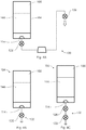
Fig. 1 is a schematic, front elevation view of a dispensing device having a base and a refill connected with the base. -
Fig. 2 is a schematic, perspective view of a refill disconnected from a base. -
Fig. 3 is a schematic, front elevation view of a dispensing device with a refill disconnected from a base. -
Fig. 4A is a schematic, side elevation view of a portion of a dispensing device, including a refill and a first dispensing system. -
Fig. 4B is a schematic, side elevation view of a portion of a dispensing device, including a refill and a second dispensing system. -
Fig. 4C is a schematic, side elevation view of a portion of a dispensing device, including a refill and a first dispensing system. -
Fig. 5A is a schematic, sectional view of portion of a refill and a portion of a base of a dispensing device. -
Fig. 5B is a schematic, sectional view of portion of a refill and a portion of a base of a dispensing device. -
Fig. 6 is a schematic of a first dispensing system configured as an electronic dispensing system. -
Fig. 7 is a schematic, side elevation view of a dispensing device having a base and a refill connected with the base. -
Fig. 8 is a schematic, side elevation view of a dispensing device having a power switch. -
Fig. 9 is a schematic, side elevation view of a dispensing device having a first actuator configured as a sensor. - Various non-limiting exemplary configurations of the present disclosure will now be described to provide an overall understanding of the principles of the structure, function, manufacture, and use of the dispensing device disclosed herein. One or more examples of these non-limiting exemplary configurations are illustrated in the accompanying drawings. Those of ordinary skill in the art will understand that the dispensing devices described herein and illustrated in the accompanying drawings are non-limiting example configurations and that the scope of the various non-limiting configurations of the present disclosure are defined solely by the claims. The features illustrated or described in connection with one non-limiting exemplary configuration may be combined with the features of other non-limiting exemplary configurations. Such modifications and variations are intended to be included within the scope of the present invention, as defined by the appended claims.
- The present disclosure includes a dispensing device. The dispensing device includes a base and a refill removably connectable with the base. The refill may be configured to contain a cleaning or personal care composition. The dispensing device is selectively operable in a first mode of operation and a second mode of operation. In a first mode of operation, a user is able to dispense a quantity of cleaning or personal care composition from the base using a single-handed action while the refill is connected with the base of the device. In a second mode of operation, a user is able to quickly remove the refill from the base and dispense a desired quantity of cleaning or personal care composition directly from the refill.
- The dispensing device of the present disclosure may be used to dispense a wide range of fluid compositions in the form of liquid, gel, foam, spray, mousse, mist, and the like. The composition may be a multi-phase composition, comprising a liquid and a gas, for example. For example, the dispensing device of the present disclosure is capable of dispensing compositions such as detergents or soaps, including dish washing compositions, hand washing compositions, laundry compositions, hard surface cleaning compositions, and personal cleansing compositions. The dispensing device may also be used to dispense various other cleaning and personal care compositions. The dispensing device may be configured to dispense liquids, gels, foams, sprays, and mists of various different viscosities. It is to be appreciated that the form of the composition dispensed from the dispensing device may be different from the form of the composition contained within the refill. For example, the composition contained within the refill may be in the form of a liquid, and the composition dispensed from the dispensing device may be in the form of foam. While the present disclosure discusses the use of the dispensing device for dispensing cleaning compositions, it is to be appreciated that various compositions may be used with the dispensing device disclosed herein.
- The base of the dispensing device may have a feed tube and a nozzle. The dispensing device may include a first dispensing system that is in fluid communication with the feed tube of the base for dispensing the composition from the base. The dispensing device includes a first actuator communicably connected with the first dispensing system. The refill of the dispensing device comprises a reservoir having a sidewall and an orifice. The refill also comprises a second dispensing system in fluid communication with the orifice of the refill and a second actuator communicably connected with the second dispensing system.
- The first dispensing system may be configured as an electronic dispensing system or a mechanical dispensing system. The second dispensing system may be configured as an electronic dispensing system or a mechanical dispensing system.
- The first dispensing system may be configured as an electronic dispensing system and the second dispensing system may be configured as a mechanical dispensing system.
- In a first mode of operation, the orifice of the refill is in fluid communication with the feed tube of the base. In the first mode of operation, activating the first actuator triggers the first dispensing system to dispense a composition from the refill. In a second mode of operation, the orifice of the refill is disconnected from the feed tube of the base. In the second mode of operation, activating the second actuator triggers the second dispensing system of the refill to dispense the composition from the refill.
- The first actuator may be configured as an electronic actuator or a mechanical actuator. The second actuator may be configured as an electronic actuator or a mechanical actuator. In some exemplary configurations, the first actuator comprises an optical sensor. In some exemplary configurations, the second actuator comprises the sidewall of the refill. In such a configuration, compression of the sidewall of the refill causes the fluid composition to release through the orifice.
- As shown in
Fig. 1 , adispensing device 100 includes abase 102 and arefill 104 that is releasably connectable with thebase 102. With reference toFigs. 1-3 , therefill 104 includes areservoir 106 configured to contain a volume of composition. Thereservoir 106 includes asidewall 108. Thesidewall 108 may terminate at abottom wall 110 at one end and at atop wall 112 at the opposite end. Thereservoir 106 also includes anorifice 114 for releasing the composition from therefill 104. As shown inFig. 2 , the reservoir may include anair vent 116 for replacing the dispensed cleaning composition volume with air to prevent drawing a vacuum. The base 102 may include afeed tube 118 that is configured to connect with theorifice 114 of therefill 104 to provide fluid communication between therefill 104 and thebase 102. The base 102 also has anozzle 120 for dispensing the composition through thebase 102. - With reference to
Figs. 1 and 2 , thebase 102 includes afirst actuator 122 and therefill 104 includes asecond actuator 124. As discussed in more detail below, in a first mode of operation, therefill 104 is connected with thebase 102 and a composition may be dispensed from thenozzle 120 by activating thefirst actuator 122. In a second mode of operation, therefill 104 may be removed from thebase 102 and thesecond actuator 124 may be activated to dispense a composition directly from theorifice 114 of therefill 104. - With reference to
Figs. 1-4A , thefirst actuator 122 is communicably connected with afirst dispensing system 130. Activating thefirst actuator 122 triggers thefirst dispensing system 130 to dispense an amount of composition from thenozzle 120 of thebase 102. Thefirst actuator 122 may be in electrical or mechanical communication with thefirst dispensing system 130. With reference toFigs. 1-4B , thesecond actuator 124 is communicably connected with asecond dispensing system 132. Activating thesecond actuator 124 triggers thesecond dispensing system 132 to dispense an amount of composition from therefill 104. Thesecond actuator 124 may be communicably connectable with thesecond dispensing system 132 in various ways, including mechanically and electrically. - The first and
second dispensing systems dispensing device 100. For example, with reference toFigs. 1 and4A , thefirst dispensing system 130 may include avalve 128 disposed adjacent to thenozzle 120 of the base 102 to control release of composition from thenozzle 120. With reference toFigs. 1 and4B , thesecond dispensing system 132 may include avalve 126 disposed adjacent to theorifice 114 of therefill 104 to control release of composition from thereservoir 106. In some exemplary configurations, thevalve 126 of thesecond dispensing system 132 may be disposed in the interior of therefill 102 adjacent to theorifice 114. - Any type of valve may be used in the first and
second dispensing systems second dispensing systems - With reference to
Figs. 4A and5A , when therefill 104 is connected with thebase 102, thefeed tube 118 of the base 102 may engage thevalve 126 of thesecond dispensing system 132 to provide fluid communication between therefill 104 and thebase 102. In such an exemplary configuration, thevalve 126 of thesecond dispensing system 132 may control release of the composition from thedispensing device 100. With reference toFigs. 4B and5B , when therefill 104 is disconnected from thebase 102, thevalve 126 of thesecond dispensing system 132 may control the release of composition from therefill 104. - The
first dispensing system 130 may be configured as an electronic dispensing system or a mechanical dispensing system. In a configuration comprising an electronic dispensing system for thefirst dispensing system 130, the electronic dispensing system, such as shown inFig. 6 , may include anelectric motor 134. Theelectric motor 134 may power anelectronic pump 138 or an electronic valve that is configured to control the flow of the composition from therefill 104. Theelectric motor 134 is powered by apower source 136. Thepower source 136 can be a battery or an AC outlet. - An electronic dispensing system may be configured in various ways. With reference to
Figs 1-4A and6 , in some exemplary configurations, an electronic dispensing system may comprise anelectronic pump 138 for delivering a composition from therefill 104 to thenozzle 120. In such an exemplary configuration, when thefirst actuator 122 is activated, theelectric motor 134 turns on and theelectronic pump 138 forces the composition from therefill 104 to thenozzle 120. Various electronic pumps may be used, including diaphragm, gear, piston pumps, peristaltic pumps, rolling bellow pumps, and the like. - In the exemplary configuration shown in
Fig. 7 , the composition may flow by gravity from therefill 104 to thenozzle 120. In such an exemplary configuration, thedispensing device 100 may include an electronic valve or an electronic pump. With reference toFigs. 4C and7 , in an exemplary configuration comprising an electronic valve, once thefirst actuator 122 is activated, themotor 134 turns on and causes thevalve 128 to open and the composition to subsequently flow out of thenozzle 120. - The electronic dispensing system may comprise a circuit board, such as a printed circuit board (PCB). The printed circuit board may provide additional functionality to the dispensing device. For example, the PCB may be used to optimize power consumption, enable timed dispensing, control a light source, and the like. The PCB may also provide a convenient mechanism for connecting the first actuator, motor, and power source. A PCB may also include an electronic member that is configured to recognize a particular refill configuration in order to ensure that replacement refills are configured to operate with the base.
- In the configuration shown in
Fig. 8 , the electronic dispensing system comprises apower switch 140 that is capable of controlling power to the electronic dispensing system. Thepower switch 140 can be configured as a toggle switch, a push-button switch, or a soft touch switch, for example. Thepower switch 140 can be turned to an "on" or "off position to control the flow of electricity to the electronic dispensing system. In an exemplary configuration comprising apower switch 140, activation of thefirst actuator 122 of the base 102 will only trigger the electronic dispensing system to dispense a composition from therefill 104 when thepower switch 140 is in the "on" position. - In some exemplary configurations, the
first dispensing system 130 maybe configured as a mechanical dispensing system. The mechanical dispensing system may be configured in various ways. For example, thevalve 128 of thefirst dispensing system 130 may be configured as a mechanical valve. Exemplary mechanical valves include elastomeric valves, mechanical check valves, slitted elastomeric membranes, duck bill valves, umbrella valves, and the like. The mechanical dispensing system may include a mechanical pump. Exemplary mechanical pumps include a mechanically operated piston pump. However, any mechanical pump for pumping fluids may be used. - In the exemplary configuration shown in
Fig. 7 , thefirst dispensing system 130 of thedispensing device 100 may be configured as a mechanical dispensing system having a mechanical valve. In such an exemplary configuration, the composition may flow by gravity from therefill 104 to thenozzle 120. Actuation of thefirst actuator 122 may cause the mechanical valve of thefirst dispensing system 130 to open and the composition to dispense from thenozzle 120. - The
second dispensing system 132 may be configured as an electronic dispensing system or a mechanical dispensing system. For example, thesecond dispensing system 132 may be configured as a mechanical dispensing system. The mechanical dispensing system may be configured in various ways. For example, thevalve 126 of thesecond dispensing system 132 may be configured as a mechanical valve. Exemplary mechanical valves include elastomeric valves, mechanical check valves, slitted elastomeric membranes, duck bill valves, umbrella valves, and the like. Themechanical dispensing system 132 may also include a mechanical pump. Exemplary mechanical pumps include a mechanically operated piston pump, peristaltic pumps, rolling bellow pumps, and the like. However, any mechanical pump for pumping fluids may be used. - With reference to
Fig. 2 , therefill 104 is configured such that the composition contained therein may be poured from therefill 104 when therefill 104 is disconnected from thebase 102. For example, the composition may flow freely from thereservoir 106 and through theorifice 114 onto a target surface. In such an exemplary configuration, the second dispensing system may include a mechanical valve that opens by the force of the composition contained within the refill applying pressure to the valve. In another exemplary configuration wherein the composition is able to flow freely from the refill when the refill is disconnected from the base, the second dispensing system may not comprise a valve such that the composition is unrestricted from flowing out of the orifice of the refill. - The
second dispensing system 132 may include an electronic dispensing system. The electronic dispensing system may include an electric motor. The electric motor may power an electronic pump or an electronic valve that is configured to control the flow of the composition from the refill. The electric motor may be powered by a power source. The power source can include battery or an AC outlet. - The electronic dispensing system may be configured in various ways. In some exemplary configurations, the electronic dispensing system may comprise an electronic pump for delivering a composition from the refill to the nozzle. In such an exemplary configuration, when the second actuator of the base is activated, the motor turns on and the electronic pump forces the composition from the refill. Various electronic pumps may be used, including diaphragm, gear, piston pumps, and the like. In some exemplary configurations, the valve of the second dispensing system may be configured as an electronic valve to control the flow of composition from the refill.
- The electronic dispensing system may comprise a circuit board, such as a printed circuit board (PCB).
- The first and
second actuators dispensing device 100 may be configured in different ways. For example, thefirst actuator 122 may be configured as a mechanical actuator such as shown inFigs. 1 and7 , or may be configured as an electronic actuator as shown inFig. 9 . Exemplary mechanical actuators include levers, push-buttons, switches, and the like. Exemplary electronic actuators include sensors such as optical sensors, motion sensors, light sensors, pressure sensors, heat sensors, and the like. Thefirst actuator 122 may be positioned in various positions relative to thebase 102. Thefirst actuator 122 is positioned below thenozzle 120. In thedispensing device 100 as shown inFig. 1 , thefirst actuator 122 is positioned below thenozzle 120. In such an exemplary configuration, a user is able to activate thefirst actuator 122 and dispense a composition onto a cleaning implement or into the user's hand using only one hand. - The
second actuator 124 may be configured in different ways. For example, thesecond actuator 124 may be configured as a mechanical actuator such as shown inFig. 1 . In other exemplary configurations, the second actuator may be configured as an electronic actuator. Exemplary mechanical actuators include levers, push-buttons, switches, and the like. In other exemplary configurations, thesidewall 108 may be flexible and thesecond actuator 124 may comprise theflexible sidewall 108 of thereservoir 106. In such an exemplary configuration, compression of thesidewall 108 causes thevalve 126 of thesecond dispensing system 132 to open and the composition to dispense there from. Exemplary electronic actuators include sensors such as optical sensors, motion sensors, light sensors, pressure sensors, heat sensors, and the like. - While
Figs. 1 and7 show twoexemplary dispensing devices 100, it is to be appreciated that the components of the dispensing device may be configured in many different ways. For example, thebase 102 of thedispensing device 100 may be configured in various ways. Thebase 102 of thedispensing device 100 may be configured to rest on a rigid surface, such as a countertop. Thebase 102 is configured to house components of thedispensing device 100, such as thefirst dispensing system 130, and to support therefill 104. Thebase 102 and therefill 104 can be arranged in different configurations relative to each other. For example, as shown inFig. 1 , thenozzle 120 andfirst actuator 122 are arranged in a side-by-side configuration with therefill 104. In other exemplary configurations, such as shown inFig. 7 , therefill 104 may rest on top of thebase 102 and thenozzle 120 andfirst actuator 122 may be positioned below therefill 104. In other exemplary configurations, therefill 104 may be positioned below thenozzle 120 andfirst actuator 122. It is to be appreciated that therefill 104 of thedispensing device 100 shown inFig. 7 is removably connectable with thebase 102. - As shown in
Fig. 1 , thebase 102 may include abuffer reservoir 152 for containing an amount of composition. For example, thebuffer reservoir 152 may be used to hold a portion of the composition dispensed from therefill 104 using the first dispensing system. In a dispensing device having abuffer reservoir 152, an amount of composition can be dispensed from the base 102 while therefill 104 is disconnected from thebase 102. - The base 102 may be comprised of various materials. For example, the
base 102 may be comprised of a rigid material, including a rigid polymeric material like polypropylene, metal, or combinations thereof. - In the configuration shown in
Fig. 1 , thebase 102 comprises one ormore feet 142 to improve the stability of the base 102 sitting on a rigid surface. Moreover, thefeet 142 may be padded to limit movement of thebase 102 and to prevent scratching the rigid surface with the bottom of thebase 102. - With reference to
Figs. 1 and 2 , thereservoir 106 may be configured in various ways. In some exemplary configurations, thebottom wall 110 and/ortop wall 112 may be removably connectable with thesidewall 108 of thereservoir 106. - The
reservoir 106 may be configured as a dual or multi-chamber reservoir that is capable of separately containing two or more compositions. - The
reservoir 106 may be configured in an upright configuration wherein the composition is released from the orifice in an upward direction. Thereservoir 106 may also be configured in a downward configuration wherein the composition is released from the orifice in a downward direction. - The
reservoir 106 of therefill 104 maybe comprised of various materials. For example, thereservoir 106 may be comprised of a rigid or semi-rigid polymeric material such as polyethylene or polypropylene. Thereservoir 104 may be comprised of other materials such as metal or glass, for example. In some exemplary configurations, thereservoir 106 may be configured as a polybag. The reservoir may be configured as a multilayer laminated pouch or a bag-in-bottle. - The refill may be configured as a bag-in-bottle system. A bag-in-bottle system may include an inner, deformable reservoir and an outer, rigid reservoir. The inner reservoir is configured to contain the composition in an airless environment, thus not needing an air vent as a conventional refill reservoir. Air can be introduced in the space between the inner and outer reservoir, thereby increasing the air pressure around the inner reservoir, causing the inner reservoir to compress and the composition to dispense therefrom. The composition may also be dispensed from a bag-in-bottle system by sucking the composition out using underpressure. A bag-in-bottle system may be formed using blow-molding technology.
- The
refill 104 may be configured to stand on a rigid surface independent of thebase 102. For example, thebottom wall 110 of thereservoir 106 may be flat in order to stably rest on a rigid surface. - The
refill 104 may be connected with the base 102 in various ways. For example, therefill 104 may be slideably or threadably connected with thebase 102. In some exemplary configurations, therefill 104 may connect with the base 102 using fasteners, pins, latches, keys and matching key ways, and the like. - The
refill 104 may be filled with a composition as presented to the user. When the composition is depleted from therefill 104, the refill may be discarded and replaced with arefill 104 having a fresh supply of a composition. Alternatively, therefill 104 may be replenished with a composition from a separate supply by the user. In such an exemplary configuration, therefill 104 may include a fill port for refilling the reservoir with a composition. In some exemplary configurations, the top orbottom wall sidewall 108 for the purpose of refilling thereservoir 106. - With reference to
Figs. 2 and3 , in a refill configuration comprising anair vent 116, theair vent 116 may be configured in various ways. In some exemplary configurations, theair vent 116 may comprise a valve 150 such as an umbrella valve. An umbrella valve is activated if the pressure inside of therefill 104 is lower than atmospheric pressure, causing atmospheric air to push past the umbrella valve and vent therefill 104. When the composition is not being actively dispensed from therefill 104, the umbrella valve is closed and the composition is unable to exit through the umbrella valve. It is to be appreciated that a minimum distance between theair vent 116 and thefeed tube 118 prevents the entrainment of air bubbles into the composition exiting therefill 104. Theair vent 116 can be positioned in different locations. As shown inFig. 2 , the air vent may be positioned in thebottom wall 110 of thereservoir 106. In other exemplary configurations, theair vent 116 may be positioned in thetop wall 112 orsidewall 108 of thereservoir 106. Theair vent 116 may mate with anair vent member 119 of thebase 102. It is to be appreciated that theair vent 116 may be configured in a closed configuration when therefill 104 is disconnected from thebase 102. When therefill 104 is connected with thebase 102, theair vent member 119 of the base 102 may be configured to open theair vent 116 to allow air to enter the reservoir. - As discussed above and as shown in
Fig. 1 , thebase 102 includes anozzle 120 for dispensing the composition. Any type of nozzle may be used depending upon the physical characteristics of the composition. For example, the nozzle may be configured to dispense the composition as a stream, mist, or a spray. The nozzle may be sized to match the desired flow rate of the composition. - As shown in
Fig. 1 , thedispensing device 100 may also comprise a cleaning implementholder 146 for holding a cleaning implement 154. The cleaning implementholder 146 may be configured to hold various cleaning implements, such as sponges, brushes, towels, and the like. The cleaning implement may be configured as a combination cleaning implement that includes, for example, a sponge and a brush. The cleaning implementholder 146 may be configured to hold one or more cleaning implements. The cleaning implementholder 146 may be positioned in various locations relative to the base of the dispensing device. The cleaning implementholder 146 may be disposed in an area of the base that is easy for a user to reach when standing in front of the dispensing device. The cleaning implementholder 146 may be integrally formed with thebase 102, or may be a separate component attached to thebase 102. The cleaning implementholder 146 may be comprised of the same material as thebase 102, or may be a different material than thebase 102. - With reference to
Figs. 1-5B , thedispensing device 100 may be used in methods of dispensing various compositions, such as cleaning and personal care compositions. For easy access, thedispensing device 100 may be placed on a rigid surface, such as a countertop or sink. Sometimes, a user may want to dispense acomposition 144 into the user's hand or onto a cleaning implement. In such a situation, with therefill 104 connected with thebase 102, the user may activate thefirst actuator 122 of thedispensing device 100 to dispense a quantity of acomposition 144 from thebase 102. In the dispensing device according to the invention, activation of thefirst actuator 122 causes thefirst dispensing system 130 to dispense a quantity of acomposition 144 from therefill 104 through thenozzle 120 of thebase 102. - In some instances, a user may hold a cleaning implement in one hand and may use the same hand to activate the
first actuator 122. As such, thedispensing device 100 may be configured for one-handed dispensing. - In another exemplary situation, a user may wish to dispense a
composition 144 directly onto a surface, such as a soiled dish or clothing item. In such a situation, the user may disconnect therefill 104 from thebase 102 and activate thesecond actuator 124 to dispense a quantity of the composition directly from therefill 104. In the dispensing device according to the invention, activation of thesecond actuator 124 causes thesecond dispensing system 132 to dispense a quantity of thecomposition 144 directly from therefill 104. Therefill 104 may offer a user a flexible design that can be placed on a countertop or easily held in a user's hand for various different dispensing purposes. - In an exemplary configuration wherein the first mode of operation includes use of an electronic dispensing system, with reference to
Figs. 1-5B , therefill 104 is connected with thefeed tube 118 of thebase 102. Activation of thefirst actuator 122 closes the electric circuit, causing theelectric motor 134 to start up. In an exemplary configuration comprising anelectronic pump 138 such as shown inFig. 4 , theelectric motor 134 drives theelectronic pump 138 to force the composition from therefill 104 into thefeed tube 118. From thefeed tube 118, thecomposition 144 flows through theelectronic pump 138 in thebase 102 and out of thenozzle 120. When the electronic dispensing system is activated, thevalve 128 adjacent to thenozzle 120 is configured to open to allow the composition to flow out of thenozzle 120. - In an exemplary configuration wherein the second mode of operation includes use of a mechanical dispensing system, the
refill 104 is disconnected from the base. In an exemplary configuration such as shown inFig. 1 wherein thesecond actuator 124 comprises thesidewall 108 of thereservoir 106, the user compresses thesidewall 108, which forces thevalve 126 of thesecond dispensing system 132 to open and the composition to flow out of theorifice 114. - The
first dispensing system 130 may be configured to dose a predetermined amount ofcomposition 144 in a single activation of thefirst actuator 122. Thesecond dispensing system 132 may be configured such that the user is able to control the amount ofcomposition 144 dosed from therefill 104 during a single activation of thesecond actuator 124. For example, the user can control the amount of composition dosed from therefill 104 in one use by holding down thesecond actuator 124 for a certain length of time. That is, the longer thesecond actuator 124 is activated themore composition 144 that is dispensed from therefill 104. In other exemplary configurations, a single activation of thesecond actuator 124 may dose a predetermined amount ofcomposition 144 from therefill 104. - The
dispensing device 100 may be use to dispense a composition onto a target surface. The target surface can be any surface, including a user's hand, a cleaning implement, or a soiled surface. As shown inFigs. 7-9 , the target surface may be a cleaning implement 154. When the target surface is a cleaning implement 154, such as shown inFigs. 7-9 , thefirst actuator 122 may be activated with the cleaning implement 154 or with a user's hand. - The dimensions and values disclosed herein are not to be understood as being strictly limited to the exact numerical values recited. Instead, unless otherwise specified, each such dimension is intended to mean both the recited value and a functionally equivalent range surrounding that value. For example, a dimension disclosed as "40 mm" is intended to mean "about 40 mm."
- While particular embodiments of the present disclosure have been illustrated and described, it would be obvious to those skilled in the art that various other changes and modifications can be made without departing from the scope of the invention. It is therefore intended to cover in the appended claims all such changes and modifications that are within the scope of this invention.
Claims (13)
- A dispensing device (100) for dispensing a fluid composition selectively operable in a first mode of operation and a second mode of operation, the device (100) comprising a base (102) and a refill (104) removably connectable with the base (102), the base (102) comprising:a first dispensing system (130);a first actuator (122) communicably connected with the first dispensing system (130), the refill comprising a reservoir (106) having a sidewall (108) and an orifice (114); andthe refill (104) comprising a second dispensing system (132) in fluid communication with the orifice (114) of the refill (104); andthe base (102) further comprising a nozzle (120) that is in fluid communication with the first dispensing system (130);wherein the first dispensing system (130) is in fluid communication with the refill (104) in the first mode of operation, andwherein the refill (104) is disconnected from the base (102) in the second mode of operation, wherein the refill (104) comprises a second actuator (124) that is communicably connected with the second dispensing system (132) and the nozzle (120) is located above the first actuator (122).
- The device (100) according to claim 1, wherein the first dispensing system (130) is configured as dispensing system selected from the group consisting of: an electronic dispensing system, a mechanical dispensing system, and combinations thereof.
- The device (100) according to claim 1-2, wherein the second dispensing system (132) is configured as a dispensing system selected from the group consisting of: an electronic dispensing system, a mechanical dispensing system, and combinations thereof.
- The device (100) according to any of the preceding claims, wherein the first actuator (122) is configured as an actuator selected from the group consisting of: a mechanical actuator, an electronic actuator, and combinations thereof.
- The device (100) according to any of Claims 1-4, wherein the second actuator (124) is configured as an actuator selected from the group consisting of: a mechanical actuator, an electronic actuator, and combinations thereof.
- The device (100) according to any of claims 1-5, wherein the sidewall (108) of the reservoir (106) is flexible, wherein the second actuator (124) comprises the flexible sidewall (108).
- The device (100) according to any of the preceding claims, wherein the base (102) further comprises a cleaning implement holder (146).
- The device (100) according to any of the preceding claims, wherein the base (102) further comprises a feed tube (118), wherein the feed tube (118) is releasably connectable with the orifice (114) of the reservoir (106).
- The device (100) according to any of the preceding claims, wherein the refill (104) is arranged in a side-by-side configuration with the first actuator (122).
- The device (100) according to any of the preceding claims, wherein the first dispensing system (130) comprises a valve (128).
- The device (100) according to any of the preceding claims, wherein the first dispensing system (130) comprises a pump.
- The device (100) according to any of claims 1-11, wherein the second dispensing system (132) comprises a valve (126).
- The device (100) according to any of claims 1-12, wherein the second dispensing system (132) comprises a pump.
Applications Claiming Priority (2)
| Application Number | Priority Date | Filing Date | Title |
|---|---|---|---|
| US14/511,204 US9884336B2 (en) | 2014-10-10 | 2014-10-10 | Multifunctional dispensing device for dispensing fluid compositions |
| PCT/US2015/054342 WO2016057586A1 (en) | 2014-10-10 | 2015-10-07 | Multifunctional dispensing device for dispensing fluid compositions |
Publications (2)
| Publication Number | Publication Date |
|---|---|
| EP3203890A1 EP3203890A1 (en) | 2017-08-16 |
| EP3203890B1 true EP3203890B1 (en) | 2019-01-09 |
Family
ID=54345600
Family Applications (1)
| Application Number | Title | Priority Date | Filing Date |
|---|---|---|---|
| EP15784521.5A Not-in-force EP3203890B1 (en) | 2014-10-10 | 2015-10-07 | Multifunctional dispensing device for dispensing fluid compositions |
Country Status (5)
| Country | Link |
|---|---|
| US (1) | US9884336B2 (en) |
| EP (1) | EP3203890B1 (en) |
| JP (2) | JP2017531492A (en) |
| CA (1) | CA2961039A1 (en) |
| WO (1) | WO2016057586A1 (en) |
Families Citing this family (6)
| Publication number | Priority date | Publication date | Assignee | Title |
|---|---|---|---|---|
| CA3032151A1 (en) * | 2016-08-04 | 2018-02-08 | Rsc Chemical Solutions, Llc | Multi-functional fluid dispensing system and associated methods for dispensing |
| US10660983B2 (en) * | 2017-05-18 | 2020-05-26 | Audrey Jean Jennings | Hand sanitizing station |
| CN115023292A (en) * | 2019-11-15 | 2022-09-06 | 爱黛化妆品国际有限公司 | Pump dispenser, filling device and refilling system with multiple pump dispensers |
| US11596269B2 (en) | 2020-01-21 | 2023-03-07 | Kerrick Patterson | Liquid dispensing container and housing assembly |
| JP6935823B2 (en) * | 2020-02-28 | 2021-09-15 | 東洋製罐株式会社 | Closure device and flexible packaging container |
| WO2021236272A1 (en) * | 2020-05-20 | 2021-11-25 | Rac-Sta, Llc | Touchless sanitizer combination device |
Family Cites Families (26)
| Publication number | Priority date | Publication date | Assignee | Title |
|---|---|---|---|---|
| US3118573A (en) * | 1961-09-22 | 1964-01-21 | Sta Safe Corp | Squeeze bottle |
| US4456152A (en) * | 1982-05-03 | 1984-06-26 | Young Don H | Measuring and dispensing apparatus |
| JPH066789Y2 (en) * | 1988-10-28 | 1994-02-23 | 株式会社吉野工業所 | Body shampoo container |
| US5507414A (en) | 1994-03-28 | 1996-04-16 | Ong; Bon S. | Liquid cleaner dispensing apparatus |
| JPH09122564A (en) * | 1995-10-30 | 1997-05-13 | Onkyo Corp | Constant quantity discharge vessel |
| JPH11104028A (en) * | 1997-09-30 | 1999-04-20 | Sanyo Electric Co Ltd | Discharge device for liquid detergent |
| US6269837B1 (en) * | 1998-11-09 | 2001-08-07 | The Procter & Gamble Company | Rechargeable dispensing system |
| US7198175B2 (en) * | 2002-04-26 | 2007-04-03 | Heiner Ophardt | Manual or pump assist fluid dispenser |
| US7837132B2 (en) * | 2002-05-28 | 2010-11-23 | S.C. Johnson & Son, Inc. | Automated cleansing sprayer |
| US7654417B2 (en) | 2004-06-28 | 2010-02-02 | Aluta, Inc. | Refillable product dispenser and system |
| US8096445B2 (en) | 2007-02-01 | 2012-01-17 | Simplehuman, Llc | Electric soap dispenser |
| US7524125B2 (en) | 2007-06-06 | 2009-04-28 | Lambert Hubert L | Liquid soap dispensing and scrubbing tool |
| US20090212072A1 (en) * | 2008-02-25 | 2009-08-27 | Fenton John C | Liquid dispenser |
| GB0820978D0 (en) | 2008-11-17 | 2008-12-24 | Reckitt & Colman Overseas | A relief valve |
| GB0820984D0 (en) | 2008-11-17 | 2008-12-24 | Reckitt & Colman Overseas | A bottle with a tamper-proof cap |
| GB0820981D0 (en) * | 2008-11-17 | 2008-12-24 | Reckitt & Colman Overseas | Dispenser and refill unit |
| GB0912065D0 (en) | 2009-07-10 | 2009-08-19 | Reckitt & Colman Overseas | A fluid delivery system |
| CN102058336A (en) | 2009-11-18 | 2011-05-18 | 新璞修人有限公司 | Soap dispenser |
| US8308027B2 (en) | 2009-12-01 | 2012-11-13 | Regent Medical Center | Automatic soap dispenser with top-side motor and methods |
| GB201007238D0 (en) | 2010-04-30 | 2010-06-16 | Reckitt & Colman Overseas | A liquid delivery system |
| GB201007232D0 (en) | 2010-04-30 | 2010-06-16 | Reckitt & Colman Overseas | A liquid delivery system |
| GB201007226D0 (en) | 2010-04-30 | 2010-06-16 | Reckitt & Colman Overseas | A combination of a liquid container and a reill device |
| GB2484935A (en) * | 2010-10-26 | 2012-05-02 | Reckitt Benckiser Llc | Container with frangible device interface |
| CN103619226B (en) | 2011-03-04 | 2016-09-21 | 新璞修人有限公司 | It is provided with the soap allocation unit of Drop-proof valve |
| USD668492S1 (en) * | 2011-11-16 | 2012-10-09 | Maximus Products, LLC | Soap dispenser |
| GB201202578D0 (en) * | 2012-02-15 | 2012-03-28 | Reckitt Benckiser Llc | Dispenser and refill unit and dispensing methods |
-
2014
- 2014-10-10 US US14/511,204 patent/US9884336B2/en active Active
-
2015
- 2015-10-07 WO PCT/US2015/054342 patent/WO2016057586A1/en active Application Filing
- 2015-10-07 EP EP15784521.5A patent/EP3203890B1/en not_active Not-in-force
- 2015-10-07 CA CA2961039A patent/CA2961039A1/en not_active Abandoned
- 2015-10-07 JP JP2017518794A patent/JP2017531492A/en active Pending
-
2019
- 2019-06-04 JP JP2019104847A patent/JP6875455B2/en active Active
Non-Patent Citations (1)
| Title |
|---|
| None * |
Also Published As
| Publication number | Publication date |
|---|---|
| JP2019177159A (en) | 2019-10-17 |
| WO2016057586A1 (en) | 2016-04-14 |
| JP2017531492A (en) | 2017-10-26 |
| US20160101430A1 (en) | 2016-04-14 |
| EP3203890A1 (en) | 2017-08-16 |
| CA2961039A1 (en) | 2016-04-14 |
| US9884336B2 (en) | 2018-02-06 |
| JP6875455B2 (en) | 2021-05-26 |
Similar Documents
| Publication | Publication Date | Title |
|---|---|---|
| EP3203890B1 (en) | Multifunctional dispensing device for dispensing fluid compositions | |
| EP1444049B1 (en) | Foam dispenser and storage holder therefor | |
| CA2961040A1 (en) | Method of dispensing a fluid composition from a multi-functional dispensing device | |
| KR101652548B1 (en) | Anti drip fluid dispenser | |
| EP2608691B1 (en) | Compact liquid container | |
| CA2945378C (en) | Mini pump with compressible air inlet chamber for providing residual suck-back | |
| EP2648585B1 (en) | Dispenser for a foaming liquid composition with improved foam recovery feature | |
| MX2012006360A (en) | Fluid dispenser. | |
| EP3157401A1 (en) | Wet/dry sheet dispenser with dispensing cup | |
| JP2017520283A5 (en) | ||
| WO2017184915A1 (en) | Liquid dispenser for a sink faucet | |
| GB2468728A (en) | Dispensing Apparatus and Method | |
| US20130312170A1 (en) | Hand sanitizer device | |
| WO2020159454A2 (en) | Liquid soap and odor dispenser |
Legal Events
| Date | Code | Title | Description |
|---|---|---|---|
| STAA | Information on the status of an ep patent application or granted ep patent |
Free format text: STATUS: THE INTERNATIONAL PUBLICATION HAS BEEN MADE |
|
| PUAI | Public reference made under article 153(3) epc to a published international application that has entered the european phase |
Free format text: ORIGINAL CODE: 0009012 |
|
| STAA | Information on the status of an ep patent application or granted ep patent |
Free format text: STATUS: REQUEST FOR EXAMINATION WAS MADE |
|
| 17P | Request for examination filed |
Effective date: 20170315 |
|
| AK | Designated contracting states |
Kind code of ref document: A1 Designated state(s): AL AT BE BG CH CY CZ DE DK EE ES FI FR GB GR HR HU IE IS IT LI LT LU LV MC MK MT NL NO PL PT RO RS SE SI SK SM TR |
|
| AX | Request for extension of the european patent |
Extension state: BA ME |
|
| DAV | Request for validation of the european patent (deleted) | ||
| DAX | Request for extension of the european patent (deleted) | ||
| GRAP | Despatch of communication of intention to grant a patent |
Free format text: ORIGINAL CODE: EPIDOSNIGR1 |
|
| STAA | Information on the status of an ep patent application or granted ep patent |
Free format text: STATUS: GRANT OF PATENT IS INTENDED |
|
| INTG | Intention to grant announced |
Effective date: 20180711 |
|
| RIN1 | Information on inventor provided before grant (corrected) |
Inventor name: DOYLE, DOMINIC, ROBERT Inventor name: HOEFTE, PAULUS, ANTONIUS AUGUSTINUS Inventor name: GARCIA FABREGA, RUBEN Inventor name: LAHUERTA SALAS, OLGA Inventor name: GOBBER, CEDRIC |
|
| GRAS | Grant fee paid |
Free format text: ORIGINAL CODE: EPIDOSNIGR3 |
|
| GRAA | (expected) grant |
Free format text: ORIGINAL CODE: 0009210 |
|
| STAA | Information on the status of an ep patent application or granted ep patent |
Free format text: STATUS: THE PATENT HAS BEEN GRANTED |
|
| RIN1 | Information on inventor provided before grant (corrected) |
Inventor name: LAHUERTA SALAS, OLGA Inventor name: GARCIA FABREGA, RUBEN Inventor name: HOEFTE, PAULUS ANTONIUS AUGUSTINUS Inventor name: GOBBER, CEDRIC Inventor name: DOYLE, DOMINIC ROBERT |
|
| AK | Designated contracting states |
Kind code of ref document: B1 Designated state(s): AL AT BE BG CH CY CZ DE DK EE ES FI FR GB GR HR HU IE IS IT LI LT LU LV MC MK MT NL NO PL PT RO RS SE SI SK SM TR |
|
| REG | Reference to a national code |
Ref country code: GB Ref legal event code: FG4D |
|
| REG | Reference to a national code |
Ref country code: CH Ref legal event code: EP Ref country code: AT Ref legal event code: REF Ref document number: 1086287 Country of ref document: AT Kind code of ref document: T Effective date: 20190115 |
|
| REG | Reference to a national code |
Ref country code: IE Ref legal event code: FG4D |
|
| REG | Reference to a national code |
Ref country code: DE Ref legal event code: R096 Ref document number: 602015023293 Country of ref document: DE |
|
| REG | Reference to a national code |
Ref country code: NL Ref legal event code: MP Effective date: 20190109 |
|
| REG | Reference to a national code |
Ref country code: LT Ref legal event code: MG4D |
|
| PG25 | Lapsed in a contracting state [announced via postgrant information from national office to epo] |
Ref country code: NL Free format text: LAPSE BECAUSE OF FAILURE TO SUBMIT A TRANSLATION OF THE DESCRIPTION OR TO PAY THE FEE WITHIN THE PRESCRIBED TIME-LIMIT Effective date: 20190109 |
|
| REG | Reference to a national code |
Ref country code: AT Ref legal event code: MK05 Ref document number: 1086287 Country of ref document: AT Kind code of ref document: T Effective date: 20190109 |
|
| PG25 | Lapsed in a contracting state [announced via postgrant information from national office to epo] |
Ref country code: SE Free format text: LAPSE BECAUSE OF FAILURE TO SUBMIT A TRANSLATION OF THE DESCRIPTION OR TO PAY THE FEE WITHIN THE PRESCRIBED TIME-LIMIT Effective date: 20190109 Ref country code: PT Free format text: LAPSE BECAUSE OF FAILURE TO SUBMIT A TRANSLATION OF THE DESCRIPTION OR TO PAY THE FEE WITHIN THE PRESCRIBED TIME-LIMIT Effective date: 20190509 Ref country code: FI Free format text: LAPSE BECAUSE OF FAILURE TO SUBMIT A TRANSLATION OF THE DESCRIPTION OR TO PAY THE FEE WITHIN THE PRESCRIBED TIME-LIMIT Effective date: 20190109 Ref country code: NO Free format text: LAPSE BECAUSE OF FAILURE TO SUBMIT A TRANSLATION OF THE DESCRIPTION OR TO PAY THE FEE WITHIN THE PRESCRIBED TIME-LIMIT Effective date: 20190409 Ref country code: PL Free format text: LAPSE BECAUSE OF FAILURE TO SUBMIT A TRANSLATION OF THE DESCRIPTION OR TO PAY THE FEE WITHIN THE PRESCRIBED TIME-LIMIT Effective date: 20190109 Ref country code: ES Free format text: LAPSE BECAUSE OF FAILURE TO SUBMIT A TRANSLATION OF THE DESCRIPTION OR TO PAY THE FEE WITHIN THE PRESCRIBED TIME-LIMIT Effective date: 20190109 Ref country code: LT Free format text: LAPSE BECAUSE OF FAILURE TO SUBMIT A TRANSLATION OF THE DESCRIPTION OR TO PAY THE FEE WITHIN THE PRESCRIBED TIME-LIMIT Effective date: 20190109 |
|
| PG25 | Lapsed in a contracting state [announced via postgrant information from national office to epo] |
Ref country code: IS Free format text: LAPSE BECAUSE OF FAILURE TO SUBMIT A TRANSLATION OF THE DESCRIPTION OR TO PAY THE FEE WITHIN THE PRESCRIBED TIME-LIMIT Effective date: 20190509 Ref country code: RS Free format text: LAPSE BECAUSE OF FAILURE TO SUBMIT A TRANSLATION OF THE DESCRIPTION OR TO PAY THE FEE WITHIN THE PRESCRIBED TIME-LIMIT Effective date: 20190109 Ref country code: HR Free format text: LAPSE BECAUSE OF FAILURE TO SUBMIT A TRANSLATION OF THE DESCRIPTION OR TO PAY THE FEE WITHIN THE PRESCRIBED TIME-LIMIT Effective date: 20190109 Ref country code: LV Free format text: LAPSE BECAUSE OF FAILURE TO SUBMIT A TRANSLATION OF THE DESCRIPTION OR TO PAY THE FEE WITHIN THE PRESCRIBED TIME-LIMIT Effective date: 20190109 Ref country code: GR Free format text: LAPSE BECAUSE OF FAILURE TO SUBMIT A TRANSLATION OF THE DESCRIPTION OR TO PAY THE FEE WITHIN THE PRESCRIBED TIME-LIMIT Effective date: 20190410 Ref country code: BG Free format text: LAPSE BECAUSE OF FAILURE TO SUBMIT A TRANSLATION OF THE DESCRIPTION OR TO PAY THE FEE WITHIN THE PRESCRIBED TIME-LIMIT Effective date: 20190409 |
|
| REG | Reference to a national code |
Ref country code: DE Ref legal event code: R097 Ref document number: 602015023293 Country of ref document: DE |
|
| PG25 | Lapsed in a contracting state [announced via postgrant information from national office to epo] |
Ref country code: IT Free format text: LAPSE BECAUSE OF FAILURE TO SUBMIT A TRANSLATION OF THE DESCRIPTION OR TO PAY THE FEE WITHIN THE PRESCRIBED TIME-LIMIT Effective date: 20190109 Ref country code: AT Free format text: LAPSE BECAUSE OF FAILURE TO SUBMIT A TRANSLATION OF THE DESCRIPTION OR TO PAY THE FEE WITHIN THE PRESCRIBED TIME-LIMIT Effective date: 20190109 Ref country code: CZ Free format text: LAPSE BECAUSE OF FAILURE TO SUBMIT A TRANSLATION OF THE DESCRIPTION OR TO PAY THE FEE WITHIN THE PRESCRIBED TIME-LIMIT Effective date: 20190109 Ref country code: RO Free format text: LAPSE BECAUSE OF FAILURE TO SUBMIT A TRANSLATION OF THE DESCRIPTION OR TO PAY THE FEE WITHIN THE PRESCRIBED TIME-LIMIT Effective date: 20190109 Ref country code: EE Free format text: LAPSE BECAUSE OF FAILURE TO SUBMIT A TRANSLATION OF THE DESCRIPTION OR TO PAY THE FEE WITHIN THE PRESCRIBED TIME-LIMIT Effective date: 20190109 Ref country code: DK Free format text: LAPSE BECAUSE OF FAILURE TO SUBMIT A TRANSLATION OF THE DESCRIPTION OR TO PAY THE FEE WITHIN THE PRESCRIBED TIME-LIMIT Effective date: 20190109 Ref country code: SK Free format text: LAPSE BECAUSE OF FAILURE TO SUBMIT A TRANSLATION OF THE DESCRIPTION OR TO PAY THE FEE WITHIN THE PRESCRIBED TIME-LIMIT Effective date: 20190109 Ref country code: AL Free format text: LAPSE BECAUSE OF FAILURE TO SUBMIT A TRANSLATION OF THE DESCRIPTION OR TO PAY THE FEE WITHIN THE PRESCRIBED TIME-LIMIT Effective date: 20190109 |
|
| PLBE | No opposition filed within time limit |
Free format text: ORIGINAL CODE: 0009261 |
|
| STAA | Information on the status of an ep patent application or granted ep patent |
Free format text: STATUS: NO OPPOSITION FILED WITHIN TIME LIMIT |
|
| PG25 | Lapsed in a contracting state [announced via postgrant information from national office to epo] |
Ref country code: SM Free format text: LAPSE BECAUSE OF FAILURE TO SUBMIT A TRANSLATION OF THE DESCRIPTION OR TO PAY THE FEE WITHIN THE PRESCRIBED TIME-LIMIT Effective date: 20190109 |
|
| 26N | No opposition filed |
Effective date: 20191010 |
|
| PG25 | Lapsed in a contracting state [announced via postgrant information from national office to epo] |
Ref country code: SI Free format text: LAPSE BECAUSE OF FAILURE TO SUBMIT A TRANSLATION OF THE DESCRIPTION OR TO PAY THE FEE WITHIN THE PRESCRIBED TIME-LIMIT Effective date: 20190109 |
|
| PG25 | Lapsed in a contracting state [announced via postgrant information from national office to epo] |
Ref country code: TR Free format text: LAPSE BECAUSE OF FAILURE TO SUBMIT A TRANSLATION OF THE DESCRIPTION OR TO PAY THE FEE WITHIN THE PRESCRIBED TIME-LIMIT Effective date: 20190109 |
|
| PG25 | Lapsed in a contracting state [announced via postgrant information from national office to epo] |
Ref country code: MC Free format text: LAPSE BECAUSE OF FAILURE TO SUBMIT A TRANSLATION OF THE DESCRIPTION OR TO PAY THE FEE WITHIN THE PRESCRIBED TIME-LIMIT Effective date: 20190109 |
|
| REG | Reference to a national code |
Ref country code: CH Ref legal event code: PL |
|
| PG25 | Lapsed in a contracting state [announced via postgrant information from national office to epo] |
Ref country code: LU Free format text: LAPSE BECAUSE OF NON-PAYMENT OF DUE FEES Effective date: 20191007 Ref country code: CH Free format text: LAPSE BECAUSE OF NON-PAYMENT OF DUE FEES Effective date: 20191031 Ref country code: LI Free format text: LAPSE BECAUSE OF NON-PAYMENT OF DUE FEES Effective date: 20191031 |
|
| REG | Reference to a national code |
Ref country code: BE Ref legal event code: MM Effective date: 20191031 |
|
| PG25 | Lapsed in a contracting state [announced via postgrant information from national office to epo] |
Ref country code: BE Free format text: LAPSE BECAUSE OF NON-PAYMENT OF DUE FEES Effective date: 20191031 |
|
| PG25 | Lapsed in a contracting state [announced via postgrant information from national office to epo] |
Ref country code: IE Free format text: LAPSE BECAUSE OF NON-PAYMENT OF DUE FEES Effective date: 20191007 |
|
| PG25 | Lapsed in a contracting state [announced via postgrant information from national office to epo] |
Ref country code: CY Free format text: LAPSE BECAUSE OF FAILURE TO SUBMIT A TRANSLATION OF THE DESCRIPTION OR TO PAY THE FEE WITHIN THE PRESCRIBED TIME-LIMIT Effective date: 20190109 |
|
| PG25 | Lapsed in a contracting state [announced via postgrant information from national office to epo] |
Ref country code: MT Free format text: LAPSE BECAUSE OF FAILURE TO SUBMIT A TRANSLATION OF THE DESCRIPTION OR TO PAY THE FEE WITHIN THE PRESCRIBED TIME-LIMIT Effective date: 20190109 Ref country code: HU Free format text: LAPSE BECAUSE OF FAILURE TO SUBMIT A TRANSLATION OF THE DESCRIPTION OR TO PAY THE FEE WITHIN THE PRESCRIBED TIME-LIMIT; INVALID AB INITIO Effective date: 20151007 |
|
| PGFP | Annual fee paid to national office [announced via postgrant information from national office to epo] |
Ref country code: FR Payment date: 20210913 Year of fee payment: 7 |
|
| PGFP | Annual fee paid to national office [announced via postgrant information from national office to epo] |
Ref country code: GB Payment date: 20210831 Year of fee payment: 7 |
|
| PGFP | Annual fee paid to national office [announced via postgrant information from national office to epo] |
Ref country code: DE Payment date: 20210831 Year of fee payment: 7 |
|
| PG25 | Lapsed in a contracting state [announced via postgrant information from national office to epo] |
Ref country code: MK Free format text: LAPSE BECAUSE OF FAILURE TO SUBMIT A TRANSLATION OF THE DESCRIPTION OR TO PAY THE FEE WITHIN THE PRESCRIBED TIME-LIMIT Effective date: 20190109 |
|
| REG | Reference to a national code |
Ref country code: DE Ref legal event code: R119 Ref document number: 602015023293 Country of ref document: DE |
|
| GBPC | Gb: european patent ceased through non-payment of renewal fee |
Effective date: 20221007 |
|
| PG25 | Lapsed in a contracting state [announced via postgrant information from national office to epo] |
Ref country code: FR Free format text: LAPSE BECAUSE OF NON-PAYMENT OF DUE FEES Effective date: 20221031 Ref country code: DE Free format text: LAPSE BECAUSE OF NON-PAYMENT OF DUE FEES Effective date: 20230503 |
|
| PG25 | Lapsed in a contracting state [announced via postgrant information from national office to epo] |
Ref country code: GB Free format text: LAPSE BECAUSE OF NON-PAYMENT OF DUE FEES Effective date: 20221007 |