EP2885091B1 - Verfahren und vorrichtung für eine giess-walz-verbundanlage - Google Patents
Verfahren und vorrichtung für eine giess-walz-verbundanlage Download PDFInfo
- Publication number
- EP2885091B1 EP2885091B1 EP13734739.9A EP13734739A EP2885091B1 EP 2885091 B1 EP2885091 B1 EP 2885091B1 EP 13734739 A EP13734739 A EP 13734739A EP 2885091 B1 EP2885091 B1 EP 2885091B1
- Authority
- EP
- European Patent Office
- Prior art keywords
- raising
- cutting
- strand
- transport direction
- preliminary material
- Prior art date
- Legal status (The legal status is an assumption and is not a legal conclusion. Google has not performed a legal analysis and makes no representation as to the accuracy of the status listed.)
- Active
Links
Images


Classifications
-
- B—PERFORMING OPERATIONS; TRANSPORTING
- B22—CASTING; POWDER METALLURGY
- B22D—CASTING OF METALS; CASTING OF OTHER SUBSTANCES BY THE SAME PROCESSES OR DEVICES
- B22D11/00—Continuous casting of metals, i.e. casting in indefinite lengths
- B22D11/12—Accessories for subsequent treating or working cast stock in situ
-
- B—PERFORMING OPERATIONS; TRANSPORTING
- B21—MECHANICAL METAL-WORKING WITHOUT ESSENTIALLY REMOVING MATERIAL; PUNCHING METAL
- B21B—ROLLING OF METAL
- B21B1/00—Metal-rolling methods or mills for making semi-finished products of solid or profiled cross-section; Sequence of operations in milling trains; Layout of rolling-mill plant, e.g. grouping of stands; Succession of passes or of sectional pass alternations
- B21B1/46—Metal-rolling methods or mills for making semi-finished products of solid or profiled cross-section; Sequence of operations in milling trains; Layout of rolling-mill plant, e.g. grouping of stands; Succession of passes or of sectional pass alternations for rolling metal immediately subsequent to continuous casting
- B21B1/463—Metal-rolling methods or mills for making semi-finished products of solid or profiled cross-section; Sequence of operations in milling trains; Layout of rolling-mill plant, e.g. grouping of stands; Succession of passes or of sectional pass alternations for rolling metal immediately subsequent to continuous casting in a continuous process, i.e. the cast not being cut before rolling
-
- B—PERFORMING OPERATIONS; TRANSPORTING
- B21—MECHANICAL METAL-WORKING WITHOUT ESSENTIALLY REMOVING MATERIAL; PUNCHING METAL
- B21B—ROLLING OF METAL
- B21B15/00—Arrangements for performing additional metal-working operations specially combined with or arranged in, or specially adapted for use in connection with, metal-rolling mills
- B21B15/0007—Cutting or shearing the product
-
- B—PERFORMING OPERATIONS; TRANSPORTING
- B22—CASTING; POWDER METALLURGY
- B22D—CASTING OF METALS; CASTING OF OTHER SUBSTANCES BY THE SAME PROCESSES OR DEVICES
- B22D11/00—Continuous casting of metals, i.e. casting in indefinite lengths
- B22D11/12—Accessories for subsequent treating or working cast stock in situ
- B22D11/1206—Accessories for subsequent treating or working cast stock in situ for plastic shaping of strands
-
- B—PERFORMING OPERATIONS; TRANSPORTING
- B22—CASTING; POWDER METALLURGY
- B22D—CASTING OF METALS; CASTING OF OTHER SUBSTANCES BY THE SAME PROCESSES OR DEVICES
- B22D11/00—Continuous casting of metals, i.e. casting in indefinite lengths
- B22D11/12—Accessories for subsequent treating or working cast stock in situ
- B22D11/124—Accessories for subsequent treating or working cast stock in situ for cooling
-
- B—PERFORMING OPERATIONS; TRANSPORTING
- B22—CASTING; POWDER METALLURGY
- B22D—CASTING OF METALS; CASTING OF OTHER SUBSTANCES BY THE SAME PROCESSES OR DEVICES
- B22D11/00—Continuous casting of metals, i.e. casting in indefinite lengths
- B22D11/12—Accessories for subsequent treating or working cast stock in situ
- B22D11/126—Accessories for subsequent treating or working cast stock in situ for cutting
-
- B—PERFORMING OPERATIONS; TRANSPORTING
- B22—CASTING; POWDER METALLURGY
- B22D—CASTING OF METALS; CASTING OF OTHER SUBSTANCES BY THE SAME PROCESSES OR DEVICES
- B22D11/00—Continuous casting of metals, i.e. casting in indefinite lengths
- B22D11/14—Plants for continuous casting
-
- B—PERFORMING OPERATIONS; TRANSPORTING
- B21—MECHANICAL METAL-WORKING WITHOUT ESSENTIALLY REMOVING MATERIAL; PUNCHING METAL
- B21B—ROLLING OF METAL
- B21B1/00—Metal-rolling methods or mills for making semi-finished products of solid or profiled cross-section; Sequence of operations in milling trains; Layout of rolling-mill plant, e.g. grouping of stands; Succession of passes or of sectional pass alternations
- B21B1/46—Metal-rolling methods or mills for making semi-finished products of solid or profiled cross-section; Sequence of operations in milling trains; Layout of rolling-mill plant, e.g. grouping of stands; Succession of passes or of sectional pass alternations for rolling metal immediately subsequent to continuous casting
-
- B—PERFORMING OPERATIONS; TRANSPORTING
- B21—MECHANICAL METAL-WORKING WITHOUT ESSENTIALLY REMOVING MATERIAL; PUNCHING METAL
- B21B—ROLLING OF METAL
- B21B15/00—Arrangements for performing additional metal-working operations specially combined with or arranged in, or specially adapted for use in connection with, metal-rolling mills
- B21B15/0007—Cutting or shearing the product
- B21B2015/0014—Cutting or shearing the product transversely to the rolling direction
Definitions
- the present invention relates to a method and an apparatus for producing hot-rolled products in a cast-rolling composite plant.
- the invention relates to a method for the production of hot-rolled products in a cast-rolling composite plant, wherein in continuous operation a strand with slab or thin slab cross-section of an endless continuously cast semi-finished material after its complete solidification a device for cutting and discharging on a roller table in a transport direction undivided ie as a strand, the strand is then hot rolled in a finishing train, then cooled, cut and stored.
- the Applicant is a method and a so-called means for cutting and discharging for a cast-rolling complex known, with which it is possible to bridge a fault in a plant part after the means for cutting and discharging, without causing the casting operation in the Continuous casting machine must be interrupted.
- the reliability of the system is significantly increased.
- the cutting and discharging device has two shears and a discharge device located between the shears, so that continuously produced primary material can be discharged as a primary material section in the disturbance.
- a lifting device is arranged after the rear shear.
- the device for cutting and discharging has a total length of about 15 m. Due to the high length, the strip cools down more on the way to the finishing mill, more scale is produced on the strip, and the investment costs (English CAPEX) and operating costs (English OPEX) are increased.
- the overall length of the device for cutting and discharging can be reduced and the investment and operating costs of the cast-rolling composite system can be reduced, the document does not show.
- a continuous casting machine for example, for thin slab or slab sections Pre-rolling pre-rolled material (typically steel) separated by the shear.
- a lifting device and a Ausfact coupled but before the finishing train, so that the foot of the strand section is pulled away by the immediate subsequent lifting of the foot part of the strand section of the scissors, ie in Transport direction is moved.
- the lifting beam in the raised state for example, extend in the horizontal direction or in an oblique direction.
- the shears cut the precursor material passing through the shears to primary material sections with a length of 8 to 14 m.
- the scissors produced so-called scrap pieces with a length of typically about 1 m.
- the starting material section is pushed off the roller table transversely to the transport direction (for example in the horizontal direction).
- the space next to the roller table is effectively used for temporarily storing the Vormaterialabitese, for example by a stacker.
- a cast-rolling composite system of the type mentioned in which the means for cutting and conveying additionally comprises a clamping device for clamping the strand section, wherein the clamping device of the lifting device is downstream in the transport direction.
- the clamping device ensures that the foot of the strand section is automatically pulled away by lifting the strand section of the scissors. This prevents a collision between the incoming starting material and the strand section.
- the scissors is a pendulum scissors or a drum shears.
- the clamping device comprises an actuating device and in a plane normal to the transport direction two strand guide rollers, wherein the strand guide rollers can be pressed by the actuating device to the strand section.
- the Strand guide rollers pressed on the actuator to the strand section, so that is clamped on the frictional engagement between the strand guide rollers and the strand section of the strand section.
- the actuator is particularly robust when it is designed as a hydraulic cylinder.
- the clamping force can be easily adjusted and limited by the hydraulic pressure.
- the lifting device comprises at least one lifting cylinder and at least one lifting beam oriented transversely to the transport direction, wherein the lifting beam can be lifted by the lifting cylinder in the vertical direction and lowered again.
- the discharge device comprises at least one stripping cylinder, whereby a starting material section can be pushed off the roller table by the stripping cylinder transversely to the transport direction (for example in the horizontal direction).
- a lifting device between two discharge devices or a discharge device between two lifting devices is arranged in the transport direction.
- a lifting device and / or a discharge device is arranged between two roller conveyor rollers following in the direction of transport.
- the lifting device in the lowered state and the discharge device are arranged in a single region of a roller table between the scissors and the clamping device.
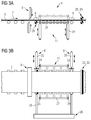
- Fig. 1 shows one from the WO 2009/121678 A1 1.
- a continuous casting machine 2 continuously produces a starting material 3 in the form of a thin slab strand, which is transported via a roller table 4 to a rough rolling mill 5.
- the starting material 3 passes through uncut, ie as a strand, a means for cutting and conveying 6 before the temperature of the starting material is set in a heating section 12 to rolling temperature.
- a descaling plant 13 which is upstream of a finishing train 14
- the descaled starting material is rolled in the single or multi-stand finishing train 14.
- the finished rolled material is then cooled in a cooling section 15, cut by a pair of scissors 16 to a certain product length or a certain product weight and then wound up by a storage device 17 designed as a take-up device.
- the roller table 4 connects all parts of the plant between the horizontal strand guide of the continuous casting machine 2 and the storage device 17th
- Fig. 2 is the device for cutting and conveying 6 of Fig. 1 shown comprising a first scissors 9a, a discharge device 8, a second scissors 9b, a lowerable roller table 18 and a lifting device 11.
- the starting material 3 is severed by the second scissors 9b, whereby a strand section 21 is formed behind the second scissors 9b.
- Vormaterial 3 the strand portion 21 of a Lifting device 11 is raised.
- the second material 9b passing through the starting material 3 is divided by the scissors 9b on scrap pieces 19, which are conveyed out via a lowerable roller table 18. Since the scrap pieces 19 are generally difficult to exploit, after the occurrence of the disturbance, the starting material 3 is cut off by a first pair of scissors 9a to precursor material portions 10, each having a length of 8-14 m, the preliminary material portions 10 being transversely across the outfeed unit 8 are transported to the transport direction 7 from the roller table 4.
- a disadvantage of the device for cutting and Auscleann 6 according to the prior art is that the length of the device 6 is about 16 m, relatively cools the starting material 3 in continuous operation due to the residence time of the starting material 3 in the device 6th a relatively strong scaling is formed, and that the investment and operating costs of the device for cutting and Auscleann 6 and the cast-rolling composite system 1 are relatively high.
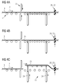
- FIGS. 3a and 3b show a first embodiment of the device according to the invention for cutting and Aus remedyn 6, the disadvantages of the solution after Fig. 2 no longer has.
- the device 6 according to the invention can also with the known casting-rolling compound 1 of Fig. 1 be used.
- the device for cutting and conveying 6 only only a pair of scissors 9, which is designed either as pendulum scissors or as a drum shears.
- the scissors 9 follow in the transport direction 7 two discharge devices 8, between which a lifting device 11 is arranged in the transport direction.
- the lifting device 11 is in the Fig. 3a, 3b pulled through in the lowered position and shown in dashed lines in the raised position.
- a clamping device 23 is arranged, which is designed as a pair of pinch rolls with which the strand section 21 or the starting material 3 can be clamped. This will prevents the strand portion 21 is moved by lifting against the transport direction 7. By clamping, the foot of the strand section 21 shifts in the transport direction 7, so that the subsequent starting material 3 has a sufficient distance from the strand section 21.
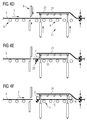
- the process steps in the device for cutting and discharging 6 after the occurrence of a fault are in the Fig. 4a ... 4f shown.
- the endlessly produced starting material 3 coming from the roughing train 5 is cut off by the scissors 9, which is designed as pendulum scissors (the Fig. 4a shows the situation before the cut).
- the Fig. 4a shows the situation before the cut.
- the strand section is clamped by the clamping device 23, so that the foot of the strand section 21 is not pulled by the lifting against the transport direction 7 (the 4b shows the situation immediately before clamping the strand section 21).
- the clamped strand portion 21 is lifted by the lifting device 11 in the vertical direction, so that the strand portion 21 has a vertical offset to the incoming material 3 and the foot of the strand portion 21 is pulled away by the lifting in the transport direction 7 of the scissors 9.
- the foot of the strand section 21 to the cutting plane of the scissors 9 has a vertical and a horizontal offset.
- the scissors 9 cuts from the starting material 3 a Vormaterialabêt 10 from.
- the starting material section 10 is accelerated by at least one driven roller 20 in the transport direction, so that the starting material section 10 has a horizontal distance to the scissors 9 ( 4e shows the situation when accelerating).
- the primary material section 10 is pushed out of the drawing plane by the two discharge devices 8 before and after the lifting device 11, so that the roller table 4 is cleared between the two discharge devices 8.
- the strand section 21 is removed, for example, by a crane 22.
- FIGS. 5a and 5b show a second embodiment according to the invention of the means for cutting and Ausfactn 6, which also with the cast-rolling compound 1 after Fig. 1 can be used.
- the difference from the first embodiment is that after the scissors 9 in the transport direction, a front lifting device 11, a discharge device 8, a rear lifting device 11 and the clamping device 23 are arranged.
- a strand section can be lifted by the two lifting devices 11.
- the subsequent starting material 3 is cut by the scissors 9 again to Vormaterialabexcellenten 10, which can be deported by the Abschubzylinder 25 of the Ausfact responded 8 from the rollers 20 of the roller table 4 in the horizontal direction on the storage arms 29 of a stacking device 26.
- a Vormaterialabêt 10 is viewed in elevation deported from the discharge device 8 of the drawing level out.
- the discharge device 8 it would also be possible to modify the discharge device 8 in such a way that a starting material section 10 is conveyed out into the plane of the drawing.
- a device suitable for this purpose is known from WO 2009/121678 A1 known.
Landscapes
- Engineering & Computer Science (AREA)
- Mechanical Engineering (AREA)
- Metal Rolling (AREA)
- Continuous Casting (AREA)
Applications Claiming Priority (2)
| Application Number | Priority Date | Filing Date | Title |
|---|---|---|---|
| ATA50328/2012A AT513299B1 (de) | 2012-08-20 | 2012-08-20 | Verfahren und Vorrichtung für eine Gieß-Walz-Verbundanlage |
| PCT/EP2013/064136 WO2014029544A1 (de) | 2012-08-20 | 2013-07-04 | Verfahren und vorrichtung für eine giess-walz-verbundanlage |
Publications (2)
| Publication Number | Publication Date |
|---|---|
| EP2885091A1 EP2885091A1 (de) | 2015-06-24 |
| EP2885091B1 true EP2885091B1 (de) | 2016-10-26 |
Family
ID=48748221
Family Applications (1)
| Application Number | Title | Priority Date | Filing Date |
|---|---|---|---|
| EP13734739.9A Active EP2885091B1 (de) | 2012-08-20 | 2013-07-04 | Verfahren und vorrichtung für eine giess-walz-verbundanlage |
Country Status (9)
| Country | Link |
|---|---|
| US (1) | US9796006B2 (enExample) |
| EP (1) | EP2885091B1 (enExample) |
| KR (1) | KR102109080B1 (enExample) |
| CN (1) | CN104540606B (enExample) |
| AT (1) | AT513299B1 (enExample) |
| IN (1) | IN2015DN00947A (enExample) |
| RU (1) | RU2633674C2 (enExample) |
| UA (1) | UA113315C2 (enExample) |
| WO (1) | WO2014029544A1 (enExample) |
Cited By (1)
| Publication number | Priority date | Publication date | Assignee | Title |
|---|---|---|---|---|
| US12186788B2 (en) | 2016-11-17 | 2025-01-07 | Sms Group Gmbh | Furnace for heating metal strips, and device and method for producing metal strips by continuous casting and rolling |
Families Citing this family (13)
| Publication number | Priority date | Publication date | Assignee | Title |
|---|---|---|---|---|
| EP2982453A1 (de) * | 2014-08-06 | 2016-02-10 | Primetals Technologies Austria GmbH | Einstellen eines gezielten Temperaturprofiles an Bandkopf und Bandfuß vor dem Querteilen eines Metallbands |
| EP3294470B1 (de) * | 2015-05-11 | 2019-07-10 | SMS group GmbH | Verfahren zur herstellung eines metallischen bandes im giesswalzverfahren |
| CN105458015B (zh) * | 2016-01-13 | 2017-12-01 | 中冶东方工程技术有限公司 | 铸轧机与连铸机的联接摆动压力控制设备及其控制方法 |
| CN110788146A (zh) * | 2018-08-01 | 2020-02-14 | 合肥江丰电子材料有限公司 | 靶材的轧制装置及轧制方法 |
| CN109351775B (zh) * | 2018-10-10 | 2021-08-20 | 首钢京唐钢铁联合有限责任公司 | 一种连铸连轧生产线剔坯方法 |
| CN111591777B (zh) * | 2020-05-20 | 2025-01-24 | 中国重型机械研究院股份公司 | 一种多流连铸出坯和热送系统及方法 |
| ES2953325T3 (es) | 2020-09-24 | 2023-11-10 | Primetals Technologies Austria GmbH | Instalación de laminación de compuestos de fundición y procedimiento para operar la instalación de laminación de compuestos de fundición |
| AT524538B1 (de) | 2021-06-09 | 2022-07-15 | Primetals Technologies Austria GmbH | Überbrückung einer Produktionsunterbrechung in einer Gieß-Walz-Verbundanlage |
| CN114101351A (zh) * | 2021-11-19 | 2022-03-01 | 一重集团大连工程技术有限公司 | 无头轧制多功能事故活套 |
| CN114834816A (zh) * | 2022-04-27 | 2022-08-02 | 湖南华菱涟源钢铁有限公司 | 板坯提升装置、板坯移动系统和板坯移动方法 |
| EP4417332B1 (de) * | 2023-02-17 | 2025-12-10 | Primetals Technologies Austria GmbH | Schrott-räumungssystem, metallband-fertigungsstrasse und schrotträumverfahren |
| CN118719805A (zh) * | 2024-07-30 | 2024-10-01 | 二重(德阳)重型装备有限公司 | 快速分切处理废带钢的装置及方法 |
| CN120394839B (zh) * | 2025-07-01 | 2025-10-14 | 烟台锐盛汽车模具有限公司 | 一种汽车零部件铸造设备 |
Family Cites Families (13)
| Publication number | Priority date | Publication date | Assignee | Title |
|---|---|---|---|---|
| DE2003263A1 (de) * | 1970-01-26 | 1971-08-05 | Kaiser Aluminium Chem Corp | Transfereinrichtung zum gleichzeitigen Herausziehen mehrerer kontinuierlich gegossener Metallstraenge aus mehreren Giesskoepfen einer Stranggiessstation |
| JPS5545530A (en) | 1978-09-25 | 1980-03-31 | Chiyoda Koutetsu Kogyo Kk | Direct rolling equipment for continuous casting having moving type continuous heating furnaces |
| JPS55100804A (en) * | 1979-01-25 | 1980-08-01 | Toshiba Corp | Manufacturing apparatus for steel rod |
| JPH04294802A (ja) * | 1991-03-20 | 1992-10-19 | Hitachi Ltd | 熱間圧延材の接合方法および装置 |
| JP2845087B2 (ja) * | 1993-05-13 | 1999-01-13 | 株式会社日立製作所 | 鋳造熱間圧延連続設備 |
| AT398396B (de) | 1993-02-16 | 1994-11-25 | Voest Alpine Ind Anlagen | Verfahren zum herstellen eines bandes, vorstreifens oder einer bramme |
| US5490315A (en) * | 1994-01-21 | 1996-02-13 | Italimpianti Of America, Inc. | Method and apparatus for continuously hot rolling strip |
| TW336184B (en) | 1995-01-11 | 1998-07-11 | Tippins Inc | Intermediate thickness slab caster and inline hot strip and plate line, method of processing metal slabs and slab container |
| GB2322320A (en) | 1997-02-21 | 1998-08-26 | Kvaerner Metals Cont Casting | Continuous casting with rolling stages separated by a temperature controlling stage |
| US7028750B2 (en) * | 2003-12-11 | 2006-04-18 | Novelis, Inc. | Apparatus and method for horizontal casting and cutting of metal billets |
| DE102008003222A1 (de) * | 2007-09-13 | 2009-03-19 | Sms Demag Ag | Kompakte flexible CSP-Anlage für Endlos-, Semi-Endlos- und Batchbetrieb |
| AT506603B8 (de) * | 2008-04-04 | 2010-03-15 | Siemens Vai Metals Tech Gmbh | Verfahren und vorrichtung für eine giess-walz-verbundanlage |
| IT1400002B1 (it) | 2010-05-10 | 2013-05-09 | Danieli Off Mecc | Procedimento ed impianto per la produzione di prodotti laminati piani |
-
2012
- 2012-08-20 AT ATA50328/2012A patent/AT513299B1/de not_active IP Right Cessation
-
2013
- 2013-04-07 UA UAA201501366A patent/UA113315C2/uk unknown
- 2013-07-04 IN IN947DEN2015 patent/IN2015DN00947A/en unknown
- 2013-07-04 RU RU2015109751A patent/RU2633674C2/ru active
- 2013-07-04 WO PCT/EP2013/064136 patent/WO2014029544A1/de not_active Ceased
- 2013-07-04 EP EP13734739.9A patent/EP2885091B1/de active Active
- 2013-07-04 US US14/420,395 patent/US9796006B2/en active Active
- 2013-07-04 KR KR1020157006764A patent/KR102109080B1/ko not_active Expired - Fee Related
- 2013-07-04 CN CN201380044458.0A patent/CN104540606B/zh active Active
Cited By (1)
| Publication number | Priority date | Publication date | Assignee | Title |
|---|---|---|---|---|
| US12186788B2 (en) | 2016-11-17 | 2025-01-07 | Sms Group Gmbh | Furnace for heating metal strips, and device and method for producing metal strips by continuous casting and rolling |
Also Published As
| Publication number | Publication date |
|---|---|
| CN104540606A (zh) | 2015-04-22 |
| AT513299A1 (de) | 2014-03-15 |
| RU2015109751A (ru) | 2016-10-10 |
| EP2885091A1 (de) | 2015-06-24 |
| WO2014029544A1 (de) | 2014-02-27 |
| IN2015DN00947A (enExample) | 2015-06-12 |
| UA113315C2 (uk) | 2017-01-10 |
| CN104540606B (zh) | 2017-02-22 |
| AT513299B1 (de) | 2016-04-15 |
| KR102109080B1 (ko) | 2020-05-12 |
| KR20150044935A (ko) | 2015-04-27 |
| US9796006B2 (en) | 2017-10-24 |
| RU2633674C2 (ru) | 2017-10-16 |
| US20150196941A1 (en) | 2015-07-16 |
Similar Documents
| Publication | Publication Date | Title |
|---|---|---|
| EP2885091B1 (de) | Verfahren und vorrichtung für eine giess-walz-verbundanlage | |
| EP2259886B1 (de) | Verfahren und vorrichtung für eine giess-walz-verbundanlage | |
| AT513298B1 (de) | Zwischenstraßenbereich einer Gieß-Walz-Verbundanlage | |
| AT514079B1 (de) | Verfahren und Vorrichtung zum schnellen Ausfördern von Grobblechen aus einem Walzwerk | |
| EP3024601B1 (de) | Verfahren und vorrichtung zur herstellung eines metallischen bandes im kontinuierlichen giesswalzverfahren | |
| EP3558563B1 (de) | Verfahren zur endlosen herstellung eines aufgewickelten warmbands in einer giess-walz-verbundanlage und giess-walz-verbundanlage | |
| EP3507030B1 (de) | Im endlosbetrieb betreibbare produktionsanlage und verfahren zum betrieb der produktionsanlage im störfall | |
| EP3027331B1 (de) | Giesswalzanlage und verfahren zum herstellen von brammen | |
| EP3089832B1 (de) | Verfahren und vorrichtung zur herstellung eines metallischen bandes im kontinuierlichen giesswalzverfahren | |
| AT524538B1 (de) | Überbrückung einer Produktionsunterbrechung in einer Gieß-Walz-Verbundanlage | |
| EP4417332B1 (de) | Schrott-räumungssystem, metallband-fertigungsstrasse und schrotträumverfahren | |
| EP4417341A1 (de) | Verfahren zum herstellen von metallischen langprodukten sowie eine giesswalzanlage für die durchführung des verfahrens | |
| EP4624065A1 (de) | Situationsabhängige metallstrangtrennung |
Legal Events
| Date | Code | Title | Description |
|---|---|---|---|
| PUAI | Public reference made under article 153(3) epc to a published international application that has entered the european phase |
Free format text: ORIGINAL CODE: 0009012 |
|
| 17P | Request for examination filed |
Effective date: 20150115 |
|
| AK | Designated contracting states |
Kind code of ref document: A1 Designated state(s): AL AT BE BG CH CY CZ DE DK EE ES FI FR GB GR HR HU IE IS IT LI LT LU LV MC MK MT NL NO PL PT RO RS SE SI SK SM TR |
|
| AX | Request for extension of the european patent |
Extension state: BA ME |
|
| DAX | Request for extension of the european patent (deleted) | ||
| GRAP | Despatch of communication of intention to grant a patent |
Free format text: ORIGINAL CODE: EPIDOSNIGR1 |
|
| INTG | Intention to grant announced |
Effective date: 20160629 |
|
| GRAS | Grant fee paid |
Free format text: ORIGINAL CODE: EPIDOSNIGR3 |
|
| GRAA | (expected) grant |
Free format text: ORIGINAL CODE: 0009210 |
|
| AK | Designated contracting states |
Kind code of ref document: B1 Designated state(s): AL AT BE BG CH CY CZ DE DK EE ES FI FR GB GR HR HU IE IS IT LI LT LU LV MC MK MT NL NO PL PT RO RS SE SI SK SM TR |
|
| REG | Reference to a national code |
Ref country code: GB Ref legal event code: FG4D Free format text: NOT ENGLISH |
|
| REG | Reference to a national code |
Ref country code: CH Ref legal event code: EP |
|
| REG | Reference to a national code |
Ref country code: AT Ref legal event code: REF Ref document number: 839635 Country of ref document: AT Kind code of ref document: T Effective date: 20161115 |
|
| REG | Reference to a national code |
Ref country code: IE Ref legal event code: FG4D Free format text: LANGUAGE OF EP DOCUMENT: GERMAN |
|
| REG | Reference to a national code |
Ref country code: DE Ref legal event code: R096 Ref document number: 502013005113 Country of ref document: DE |
|
| REG | Reference to a national code |
Ref country code: NL Ref legal event code: FP |
|
| REG | Reference to a national code |
Ref country code: LT Ref legal event code: MG4D |
|
| PG25 | Lapsed in a contracting state [announced via postgrant information from national office to epo] |
Ref country code: LV Free format text: LAPSE BECAUSE OF FAILURE TO SUBMIT A TRANSLATION OF THE DESCRIPTION OR TO PAY THE FEE WITHIN THE PRESCRIBED TIME-LIMIT Effective date: 20161026 |
|
| PG25 | Lapsed in a contracting state [announced via postgrant information from national office to epo] |
Ref country code: LT Free format text: LAPSE BECAUSE OF FAILURE TO SUBMIT A TRANSLATION OF THE DESCRIPTION OR TO PAY THE FEE WITHIN THE PRESCRIBED TIME-LIMIT Effective date: 20161026 Ref country code: GR Free format text: LAPSE BECAUSE OF FAILURE TO SUBMIT A TRANSLATION OF THE DESCRIPTION OR TO PAY THE FEE WITHIN THE PRESCRIBED TIME-LIMIT Effective date: 20170127 Ref country code: NO Free format text: LAPSE BECAUSE OF FAILURE TO SUBMIT A TRANSLATION OF THE DESCRIPTION OR TO PAY THE FEE WITHIN THE PRESCRIBED TIME-LIMIT Effective date: 20170126 Ref country code: SE Free format text: LAPSE BECAUSE OF FAILURE TO SUBMIT A TRANSLATION OF THE DESCRIPTION OR TO PAY THE FEE WITHIN THE PRESCRIBED TIME-LIMIT Effective date: 20161026 |
|
| PG25 | Lapsed in a contracting state [announced via postgrant information from national office to epo] |
Ref country code: ES Free format text: LAPSE BECAUSE OF FAILURE TO SUBMIT A TRANSLATION OF THE DESCRIPTION OR TO PAY THE FEE WITHIN THE PRESCRIBED TIME-LIMIT Effective date: 20161026 Ref country code: IS Free format text: LAPSE BECAUSE OF FAILURE TO SUBMIT A TRANSLATION OF THE DESCRIPTION OR TO PAY THE FEE WITHIN THE PRESCRIBED TIME-LIMIT Effective date: 20170226 Ref country code: RS Free format text: LAPSE BECAUSE OF FAILURE TO SUBMIT A TRANSLATION OF THE DESCRIPTION OR TO PAY THE FEE WITHIN THE PRESCRIBED TIME-LIMIT Effective date: 20161026 Ref country code: HR Free format text: LAPSE BECAUSE OF FAILURE TO SUBMIT A TRANSLATION OF THE DESCRIPTION OR TO PAY THE FEE WITHIN THE PRESCRIBED TIME-LIMIT Effective date: 20161026 Ref country code: PT Free format text: LAPSE BECAUSE OF FAILURE TO SUBMIT A TRANSLATION OF THE DESCRIPTION OR TO PAY THE FEE WITHIN THE PRESCRIBED TIME-LIMIT Effective date: 20170227 Ref country code: PL Free format text: LAPSE BECAUSE OF FAILURE TO SUBMIT A TRANSLATION OF THE DESCRIPTION OR TO PAY THE FEE WITHIN THE PRESCRIBED TIME-LIMIT Effective date: 20161026 Ref country code: FI Free format text: LAPSE BECAUSE OF FAILURE TO SUBMIT A TRANSLATION OF THE DESCRIPTION OR TO PAY THE FEE WITHIN THE PRESCRIBED TIME-LIMIT Effective date: 20161026 |
|
| REG | Reference to a national code |
Ref country code: DE Ref legal event code: R097 Ref document number: 502013005113 Country of ref document: DE |
|
| PG25 | Lapsed in a contracting state [announced via postgrant information from national office to epo] |
Ref country code: CZ Free format text: LAPSE BECAUSE OF FAILURE TO SUBMIT A TRANSLATION OF THE DESCRIPTION OR TO PAY THE FEE WITHIN THE PRESCRIBED TIME-LIMIT Effective date: 20161026 Ref country code: EE Free format text: LAPSE BECAUSE OF FAILURE TO SUBMIT A TRANSLATION OF THE DESCRIPTION OR TO PAY THE FEE WITHIN THE PRESCRIBED TIME-LIMIT Effective date: 20161026 Ref country code: RO Free format text: LAPSE BECAUSE OF FAILURE TO SUBMIT A TRANSLATION OF THE DESCRIPTION OR TO PAY THE FEE WITHIN THE PRESCRIBED TIME-LIMIT Effective date: 20161026 Ref country code: SK Free format text: LAPSE BECAUSE OF FAILURE TO SUBMIT A TRANSLATION OF THE DESCRIPTION OR TO PAY THE FEE WITHIN THE PRESCRIBED TIME-LIMIT Effective date: 20161026 Ref country code: DK Free format text: LAPSE BECAUSE OF FAILURE TO SUBMIT A TRANSLATION OF THE DESCRIPTION OR TO PAY THE FEE WITHIN THE PRESCRIBED TIME-LIMIT Effective date: 20161026 |
|
| PG25 | Lapsed in a contracting state [announced via postgrant information from national office to epo] |
Ref country code: SM Free format text: LAPSE BECAUSE OF FAILURE TO SUBMIT A TRANSLATION OF THE DESCRIPTION OR TO PAY THE FEE WITHIN THE PRESCRIBED TIME-LIMIT Effective date: 20161026 Ref country code: BG Free format text: LAPSE BECAUSE OF FAILURE TO SUBMIT A TRANSLATION OF THE DESCRIPTION OR TO PAY THE FEE WITHIN THE PRESCRIBED TIME-LIMIT Effective date: 20170126 |
|
| PLBE | No opposition filed within time limit |
Free format text: ORIGINAL CODE: 0009261 |
|
| STAA | Information on the status of an ep patent application or granted ep patent |
Free format text: STATUS: NO OPPOSITION FILED WITHIN TIME LIMIT |
|
| PGFP | Annual fee paid to national office [announced via postgrant information from national office to epo] |
Ref country code: NL Payment date: 20170719 Year of fee payment: 5 |
|
| 26N | No opposition filed |
Effective date: 20170727 |
|
| PG25 | Lapsed in a contracting state [announced via postgrant information from national office to epo] |
Ref country code: SI Free format text: LAPSE BECAUSE OF FAILURE TO SUBMIT A TRANSLATION OF THE DESCRIPTION OR TO PAY THE FEE WITHIN THE PRESCRIBED TIME-LIMIT Effective date: 20161026 |
|
| REG | Reference to a national code |
Ref country code: CH Ref legal event code: PL |
|
| GBPC | Gb: european patent ceased through non-payment of renewal fee |
Effective date: 20170704 |
|
| REG | Reference to a national code |
Ref country code: IE Ref legal event code: MM4A |
|
| REG | Reference to a national code |
Ref country code: FR Ref legal event code: ST Effective date: 20180330 |
|
| PG25 | Lapsed in a contracting state [announced via postgrant information from national office to epo] |
Ref country code: LI Free format text: LAPSE BECAUSE OF NON-PAYMENT OF DUE FEES Effective date: 20170731 Ref country code: IE Free format text: LAPSE BECAUSE OF NON-PAYMENT OF DUE FEES Effective date: 20170704 Ref country code: GB Free format text: LAPSE BECAUSE OF NON-PAYMENT OF DUE FEES Effective date: 20170704 Ref country code: CH Free format text: LAPSE BECAUSE OF NON-PAYMENT OF DUE FEES Effective date: 20170731 |
|
| PG25 | Lapsed in a contracting state [announced via postgrant information from national office to epo] |
Ref country code: FR Free format text: LAPSE BECAUSE OF NON-PAYMENT OF DUE FEES Effective date: 20170731 |
|
| REG | Reference to a national code |
Ref country code: BE Ref legal event code: MM Effective date: 20170731 |
|
| PG25 | Lapsed in a contracting state [announced via postgrant information from national office to epo] |
Ref country code: LU Free format text: LAPSE BECAUSE OF NON-PAYMENT OF DUE FEES Effective date: 20170704 |
|
| PG25 | Lapsed in a contracting state [announced via postgrant information from national office to epo] |
Ref country code: BE Free format text: LAPSE BECAUSE OF NON-PAYMENT OF DUE FEES Effective date: 20170731 |
|
| PG25 | Lapsed in a contracting state [announced via postgrant information from national office to epo] |
Ref country code: MT Free format text: LAPSE BECAUSE OF FAILURE TO SUBMIT A TRANSLATION OF THE DESCRIPTION OR TO PAY THE FEE WITHIN THE PRESCRIBED TIME-LIMIT Effective date: 20161026 |
|
| REG | Reference to a national code |
Ref country code: NL Ref legal event code: MM Effective date: 20180801 |
|
| PG25 | Lapsed in a contracting state [announced via postgrant information from national office to epo] |
Ref country code: NL Free format text: LAPSE BECAUSE OF NON-PAYMENT OF DUE FEES Effective date: 20180801 |
|
| PG25 | Lapsed in a contracting state [announced via postgrant information from national office to epo] |
Ref country code: HU Free format text: LAPSE BECAUSE OF FAILURE TO SUBMIT A TRANSLATION OF THE DESCRIPTION OR TO PAY THE FEE WITHIN THE PRESCRIBED TIME-LIMIT; INVALID AB INITIO Effective date: 20130704 Ref country code: MC Free format text: LAPSE BECAUSE OF FAILURE TO SUBMIT A TRANSLATION OF THE DESCRIPTION OR TO PAY THE FEE WITHIN THE PRESCRIBED TIME-LIMIT Effective date: 20161026 |
|
| REG | Reference to a national code |
Ref country code: AT Ref legal event code: MM01 Ref document number: 839635 Country of ref document: AT Kind code of ref document: T Effective date: 20180704 |
|
| PG25 | Lapsed in a contracting state [announced via postgrant information from national office to epo] |
Ref country code: CY Free format text: LAPSE BECAUSE OF FAILURE TO SUBMIT A TRANSLATION OF THE DESCRIPTION OR TO PAY THE FEE WITHIN THE PRESCRIBED TIME-LIMIT Effective date: 20161026 |
|
| PG25 | Lapsed in a contracting state [announced via postgrant information from national office to epo] |
Ref country code: MK Free format text: LAPSE BECAUSE OF FAILURE TO SUBMIT A TRANSLATION OF THE DESCRIPTION OR TO PAY THE FEE WITHIN THE PRESCRIBED TIME-LIMIT Effective date: 20161026 |
|
| PG25 | Lapsed in a contracting state [announced via postgrant information from national office to epo] |
Ref country code: AT Free format text: LAPSE BECAUSE OF NON-PAYMENT OF DUE FEES Effective date: 20180704 |
|
| PG25 | Lapsed in a contracting state [announced via postgrant information from national office to epo] |
Ref country code: TR Free format text: LAPSE BECAUSE OF FAILURE TO SUBMIT A TRANSLATION OF THE DESCRIPTION OR TO PAY THE FEE WITHIN THE PRESCRIBED TIME-LIMIT Effective date: 20161026 |
|
| PG25 | Lapsed in a contracting state [announced via postgrant information from national office to epo] |
Ref country code: AL Free format text: LAPSE BECAUSE OF FAILURE TO SUBMIT A TRANSLATION OF THE DESCRIPTION OR TO PAY THE FEE WITHIN THE PRESCRIBED TIME-LIMIT Effective date: 20161026 |
|
| REG | Reference to a national code |
Ref country code: DE Ref legal event code: R082 Ref document number: 502013005113 Country of ref document: DE Representative=s name: LINDNER BLAUMEIER, PATENT- UND RECHTSANWAELTE,, DE |
|
| PGFP | Annual fee paid to national office [announced via postgrant information from national office to epo] |
Ref country code: DE Payment date: 20250722 Year of fee payment: 13 |
|
| PGFP | Annual fee paid to national office [announced via postgrant information from national office to epo] |
Ref country code: IT Payment date: 20250724 Year of fee payment: 13 |