EP2884708A1 - Iterative method for synthesising digital filters for shaping a signal - Google Patents
Iterative method for synthesising digital filters for shaping a signal Download PDFInfo
- Publication number
- EP2884708A1 EP2884708A1 EP14197049.1A EP14197049A EP2884708A1 EP 2884708 A1 EP2884708 A1 EP 2884708A1 EP 14197049 A EP14197049 A EP 14197049A EP 2884708 A1 EP2884708 A1 EP 2884708A1
- Authority
- EP
- European Patent Office
- Prior art keywords
- filter
- iterative
- transmission
- reception
- filters
- Prior art date
- Legal status (The legal status is an assumption and is not a legal conclusion. Google has not performed a legal analysis and makes no representation as to the accuracy of the status listed.)
- Granted
Links
- 238000000034 method Methods 0.000 title claims abstract description 35
- 238000007493 shaping process Methods 0.000 title description 8
- 230000005540 biological transmission Effects 0.000 claims abstract description 51
- 230000002194 synthesizing effect Effects 0.000 claims abstract description 5
- 238000004364 calculation method Methods 0.000 claims abstract description 3
- 238000001308 synthesis method Methods 0.000 claims description 7
- 230000015572 biosynthetic process Effects 0.000 claims description 6
- 238000003786 synthesis reaction Methods 0.000 claims description 6
- 238000004590 computer program Methods 0.000 claims description 4
- 238000010586 diagram Methods 0.000 description 17
- 238000001914 filtration Methods 0.000 description 4
- 230000000052 comparative effect Effects 0.000 description 2
- 230000003595 spectral effect Effects 0.000 description 2
- 230000002123 temporal effect Effects 0.000 description 2
- 230000001186 cumulative effect Effects 0.000 description 1
- 230000007423 decrease Effects 0.000 description 1
- 238000001514 detection method Methods 0.000 description 1
- 230000000694 effects Effects 0.000 description 1
- 230000008030 elimination Effects 0.000 description 1
- 238000003379 elimination reaction Methods 0.000 description 1
- 230000002349 favourable effect Effects 0.000 description 1
- 238000004519 manufacturing process Methods 0.000 description 1
- 238000001228 spectrum Methods 0.000 description 1
Images

Classifications
-
- H—ELECTRICITY
- H04—ELECTRIC COMMUNICATION TECHNIQUE
- H04L—TRANSMISSION OF DIGITAL INFORMATION, e.g. TELEGRAPHIC COMMUNICATION
- H04L25/00—Baseband systems
- H04L25/02—Details ; arrangements for supplying electrical power along data transmission lines
- H04L25/03—Shaping networks in transmitter or receiver, e.g. adaptive shaping networks
- H04L25/03006—Arrangements for removing intersymbol interference
- H04L25/03012—Arrangements for removing intersymbol interference operating in the time domain
- H04L25/03019—Arrangements for removing intersymbol interference operating in the time domain adaptive, i.e. capable of adjustment during data reception
- H04L25/03057—Arrangements for removing intersymbol interference operating in the time domain adaptive, i.e. capable of adjustment during data reception with a recursive structure
-
- H—ELECTRICITY
- H04—ELECTRIC COMMUNICATION TECHNIQUE
- H04L—TRANSMISSION OF DIGITAL INFORMATION, e.g. TELEGRAPHIC COMMUNICATION
- H04L25/00—Baseband systems
- H04L25/02—Details ; arrangements for supplying electrical power along data transmission lines
- H04L25/03—Shaping networks in transmitter or receiver, e.g. adaptive shaping networks
- H04L25/03828—Arrangements for spectral shaping; Arrangements for providing signals with specified spectral properties
- H04L25/03834—Arrangements for spectral shaping; Arrangements for providing signals with specified spectral properties using pulse shaping
- H04L25/03853—Shaping by digital methods other than look up tables or up/down converters
-
- H—ELECTRICITY
- H04—ELECTRIC COMMUNICATION TECHNIQUE
- H04L—TRANSMISSION OF DIGITAL INFORMATION, e.g. TELEGRAPHIC COMMUNICATION
- H04L25/00—Baseband systems
- H04L25/02—Details ; arrangements for supplying electrical power along data transmission lines
- H04L25/03—Shaping networks in transmitter or receiver, e.g. adaptive shaping networks
- H04L25/03006—Arrangements for removing intersymbol interference
- H04L25/03012—Arrangements for removing intersymbol interference operating in the time domain
-
- H—ELECTRICITY
- H04—ELECTRIC COMMUNICATION TECHNIQUE
- H04L—TRANSMISSION OF DIGITAL INFORMATION, e.g. TELEGRAPHIC COMMUNICATION
- H04L25/00—Baseband systems
- H04L25/02—Details ; arrangements for supplying electrical power along data transmission lines
- H04L25/03—Shaping networks in transmitter or receiver, e.g. adaptive shaping networks
- H04L25/03878—Line equalisers; line build-out devices
- H04L25/03885—Line equalisers; line build-out devices adaptive
-
- H—ELECTRICITY
- H04—ELECTRIC COMMUNICATION TECHNIQUE
- H04L—TRANSMISSION OF DIGITAL INFORMATION, e.g. TELEGRAPHIC COMMUNICATION
- H04L25/00—Baseband systems
- H04L25/02—Details ; arrangements for supplying electrical power along data transmission lines
- H04L25/03—Shaping networks in transmitter or receiver, e.g. adaptive shaping networks
- H04L25/03891—Spatial equalizers
- H04L25/03949—Spatial equalizers equalizer selection or adaptation based on feedback
-
- H—ELECTRICITY
- H04—ELECTRIC COMMUNICATION TECHNIQUE
- H04L—TRANSMISSION OF DIGITAL INFORMATION, e.g. TELEGRAPHIC COMMUNICATION
- H04L25/00—Baseband systems
- H04L25/02—Details ; arrangements for supplying electrical power along data transmission lines
- H04L25/03—Shaping networks in transmitter or receiver, e.g. adaptive shaping networks
- H04L25/03006—Arrangements for removing intersymbol interference
- H04L2025/03592—Adaptation methods
- H04L2025/03598—Algorithms
- H04L2025/03611—Iterative algorithms
-
- H—ELECTRICITY
- H04—ELECTRIC COMMUNICATION TECHNIQUE
- H04L—TRANSMISSION OF DIGITAL INFORMATION, e.g. TELEGRAPHIC COMMUNICATION
- H04L25/00—Baseband systems
- H04L25/02—Details ; arrangements for supplying electrical power along data transmission lines
- H04L25/03—Shaping networks in transmitter or receiver, e.g. adaptive shaping networks
- H04L25/03006—Arrangements for removing intersymbol interference
- H04L2025/03592—Adaptation methods
- H04L2025/03598—Algorithms
- H04L2025/03681—Control of adaptation
- H04L2025/037—Detection of convergence state
-
- H—ELECTRICITY
- H04—ELECTRIC COMMUNICATION TECHNIQUE
- H04L—TRANSMISSION OF DIGITAL INFORMATION, e.g. TELEGRAPHIC COMMUNICATION
- H04L27/00—Modulated-carrier systems
- H04L27/01—Equalisers
Definitions
- the present invention relates to the field of signal shaping filters in the context of a narrow-band wireless transmission between a transmitter and a receiver.
- the invention applies more specifically to signals modulated according to a single-carrier modulation.
- the invention relates to an iterative method for synthesizing digital signal shaping filters and filters obtained by applying such a method.
- the invention is of particular interest especially when it applies to strain length filters.
- a digital signal to be transmitted is modulated and filtered before being transmitted.
- a first shaping filter is applied to a modulated signal before it is transmitted by radio and a second shaping filter, adapted to the first filter, to the signal received by a receiver before it is demodulated.
- the shaping filter applied to the transmission, and the adapted filter applied in reception, must conform to precise spectrum templates meeting many constraints.
- the intersymbol interference associated with the filters must be limited so as not to degrade the performance of the demodulation.
- the ratio between the peak power and the average power must be as low as possible in order to be able to transmit at optimum power.
- raised cosine root filters retain their good properties only when they are synthesized with a large number of coefficients. Indeed, the truncation of the filter to a number of reduced coefficients decreases the frequency selectivity of the filter.
- An alternative for improving performance is to apply a weighting window to the truncated filter, for example a Blackman window or a Hamming window, however this method generates intersymbol interference.
- the technical problem that the present invention aims to solve thus consists in finding a method for synthesizing shaping filters that makes it possible to ensure the production of filters having good properties in terms of intersymbol interference and peak factor despite their constrained length.
- the invention proposes a solution to the aforementioned problem which consists in particular in iteratively compensating inter-symbol interference in a global manner on the transmission filter equal to the convolution of the transmission filter with the reception filter.
- the invention particularly has the advantage of allowing fine adjustment of the parameters of the filters to be synthesized according to the constraints of the target mask and constraints on the lengths of the respective filters in transmission and reception.
- the choice of the convolution of the equalizing filter with the transmission filter or the reception filter is carried out in according to a desired frequency mask of the transmission filter and / or the reception filter.
- the execution iterations are stopped when the inter-symbol interference level is lower than a given threshold.
- the criterion representative of the level of inter-symbol interference on the transmission filter is taken equal to the ratio between the sum of the absolute values of the coefficients of said filter except the central coefficient and the absolute value of the coefficient. central of said filter.
- the equalizing filter is multiplied by a weighting window, the type of weighting window being selected as a function of the desired convergence speed of the iterative method.
- the emission filter and the reception filter are elevated cosine root filters.
- the raised cosine root filters are multiplied by a weighting window.
- the invention also relates to a computer program comprising instructions for executing the iterative filter synthesis method according to the invention, when the program is executed by a processor and a transmission filter or filter reception obtained from the execution of the iterative filter synthesis method according to the invention.
- the iterative method according to the invention is initialized with the generation of a first digital transmission filter 101 intended to be applied to a modulated signal to be transmitted and of a second digital reception filter 102 intended to be applied to the signal received by receiver before demodulation.
- the transmit filter 101 and the receive filter 102 may be raised cosine root filters as commonly used in the field of digital communications.
- the transmission filter 101 and the reception filter 102 are then truncated to limit their length, and therefore their number of coefficients, in order to satisfy the implementation constraints of the filtering operation in the sending and receiving equipment.
- the transmission filter 101 and the reception filter 102 may be multiplied by a weighting window 103, 104 for example a Hamming window or a Blackman window.
- the truncation operation of the filters can also be considered as a multiplication by a rectangular weighting window.
- the first iteration of the method according to the invention starts with the convolution 107 of the transmission filter 101 and the reception filter 102, the filters possibly being weighted by a window.
- the convolution operation 107 makes it possible to obtain the overall transmission filter, in other words the overall filtering operation that the signal undergoes between the output of the modulator of the sending equipment and the input of the demodulator of the receiving equipment.
- a criterion 108 representative of the intersymbol interference level on the transmission filter F trans is then calculated.
- the determination of the intersymbol interference level is a practice well known to those skilled in the art of digital communications.
- Inter-symbol interference is a distortion phenomenon which has the consequence that, when a signal is filtered by a filter having a non-zero level of intersymbol interference, the current symbol may be polluted by the preceding symbols.
- ratio D max is strictly less than 1, the eye diagram of the signal filtered by the filter R is completely open and the intersymbol interference is zero. Conversely, a ratio D max greater than 1 is indicative of the presence of inter-symbol interference.
- the method according to the invention is stopped at the current iteration and the synthesized transmission and reception filters are those obtained at the last iteration.
- an equalizer filter 110 is calculated to reduce the interference level. inter symbols.
- an equalizer filter adapted from the general knowledge of the field of digital communications as described for example in the reference work "Digital communications", John Proakis et al. chap 10-2 linear equalization.
- the equalizer filter 110 is then truncated via a windowing operation 111 to limit its number of coefficients to the number of coefficients of the transmission filter 101 or the reception filter 102.
- the truncation of the equalizing filter 110 may notably consist in selecting only the first N coefficients of the filter, N being the desired number of coefficients.
- the windowing operation 110 may also consist in multiplying the equalizing filter by a weighting window in order to parameterize the speed of convergence of the iterative method according to the invention.
- a rectangular window truncation window
- Blackman or Hamming weighting window will result in a slower convergence.
- a switching step 112 then makes it possible to orient the application of the equalizing filter on the transmission filter or on the reception filter.
- the switch 112 is set according to the proximity of the frequency response of said filters to a target template.
- the switching choice 112 is on the transmission filter 101, the latter is convoluted 105 with the equalizer filter 110 to obtain a new transmission filter Fem which serves as an entry point to the next iteration.
- the switching choice 112 is on the reception filter 102, the latter is convoluted 106 with the equalizing filter 110 to obtain a new Frec reception filter which serves as an entry point to the next iteration .
- the equalizer filter is applied to one or other of the two filters Fem, Frec and the filter resulting from this convolution replaces the filter obtained at the previous iteration.
- equalizer filter to the transmission channel or the reception channel makes it possible to better adjust the spectral characteristics of the filters, their frequency selectivity and the peak factor.
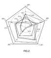
- the figure 2 illustrates, on a Kiviat diagram, the performances of digital filters synthesized via a usual method or via the iterative method according to the invention.
- the characteristics represented on the diagram of the figure 2 are those of the global transmission filter constituted by the convolution of the transmission filter and the reception filter. All transmit and receive filters used are raised cosine root filters. In the example of the figure 2 , the length of the transmission filter represents 5 1/3 symbols and the length of the reception filter represents 8 symbols.
- the diagram 210 corresponds to a transmission filter and a reception filter of drop-off coefficients (or roll-off coefficients) of 0.35 multiplied by a rectangular window and without application of the iterative method according to the invention.
- the diagram 211 corresponds to a transmission filter and a reception filter of drop-off coefficients (or roll-off coefficients) of 0.25 multiplied by a rectangular window and without application of the iterative method according to the invention.
- the diagram 212 corresponds to a transmission filter and a reception filter of drop-off coefficients (or roll-off coefficients) of 0.25 multiplied by a rectangular window and with application of the method. iterative according to the invention with a first iteration in which the equalizing filter is applied to the reception filter and a second iteration in which the equalizing filter is applied to the transmission filter.
- the diagram 213 corresponds to a transmission filter and a drop coefficient receiving filter (or roll-off coefficients) of 0.35 multiplied by a Gaussian window (the standard deviation being equal to 0.56 for the filter of FIG. transmission and at 1 for the reception filter) and with application of the iterative method according to the invention with a first iteration in which the equalizing filter is applied to the reception filter and a second iteration in which the equalizing filter is applied to the reception filter. 'program.
- the diagram 214 corresponds to a transmission filter and a filter of reception of drop-off coefficients (or roll-off coefficients) of 0.45 multiplied by a Hamming window and with application of the iterative method according to the invention with a first iteration in which the equalizer filter is applied to the receive filter and a second iteration in which the equalizer filter is applied to the transmit filter.
- the diagram 215 corresponds to a drop coefficient emission filter (or roll-off coefficient) of 0.48 multiplied by a Tukey window of parameter 0.26 and a reception coefficient filter of 0. , Multiplied by a rectangular window and with application of the iterative method according to the invention with a first iteration in which the equalizing filter is applied to the reception filter and a second iteration in which the equalizing filter is applied to the transmission filter.
- the effect of the iterative method according to the invention on the filters of dropout coefficients equal to 0.25 is important, the gain in signal to noise ratio is 0.6dB.
- the filter corresponding to the diagram 213 has characteristics that are generally better than the reference filter corresponding to the diagram 210.
- the performances in error rates are also better.
- the gain on the peak factor is about 0.20dB.
- the filter corresponding to the diagram 215 makes it possible to maximize the torque (peak factor, signal-to-noise ratio) with a cumulative gain of more than 0.4 dB.
- the iterative method of synthesis of digital filters according to the invention can be implemented as a computer program comprising instructions for its execution.
- the computer program can be recorded on a processor-readable recording medium.
Abstract
Méthode itérative de synthèse de filtres numériques comprenant les étapes suivantes :
• La génération d'un filtre d'émission (101) destiné à être appliqué à un signal à émettre,
• La génération d'un filtre de réception (102) destiné à être appliqué à un signal reçu,
ladite méthode étant caractérisée en ce qu'elle comprend les étapes suivantes exécutées itérativement :
• La convolution (107) du filtre d'émission et du filtre de réception pour générer un filtre de transmission,
• La détermination (108) d'un critère représentatif du niveau d'interférence inter-symboles sur ledit filtre de transmission et si le niveau d'interférence inter-symboles est supérieur à un niveau donné,
• Le calcul d'un filtre égaliseur de l'interférence inter-symboles (110),
• Le remplacement du filtre d'émission par le filtre d'émission convolué (105) avec le filtre égaliseur ou le remplacement du filtre de réception par le filtre de réception convolué (106) avec le filtre égaliseur.

The generation of a transmission filter (101) intended to be applied to a signal to be transmitted,
Generating a reception filter (102) to be applied to a received signal,
said method being characterized in that it comprises the following steps performed iteratively:
• The convolution (107) of the transmit filter and the receive filter to generate a transmission filter,
The determination (108) of a criterion representative of the level of intersymbol interference on said transmission filter and if the level of intersymbol interference is greater than a given level,
• The calculation of an equalizer filter of the intersymbol interference (110),
• The replacement of the transmit filter by the convolved emission filter (105) with the equalizer filter or the replacement of the reception filter by the convoluted reception filter (106) with the equalizer filter.
Description
La présente invention concerne le domaine des filtres de mise en forme d'un signal dans le cadre d'une transmission sans fils en bande étroite entre un émetteur et un récepteur. L'invention s'applique plus précisément aux signaux modulés selon une modulation mono-porteuse.The present invention relates to the field of signal shaping filters in the context of a narrow-band wireless transmission between a transmitter and a receiver. The invention applies more specifically to signals modulated according to a single-carrier modulation.
L'invention porte sur une méthode itérative de synthèse de filtres numériques de mise en forme d'un signal et sur les filtres obtenus par application d'une telle méthode.The invention relates to an iterative method for synthesizing digital signal shaping filters and filters obtained by applying such a method.
L'invention trouve un intérêt particulier notamment lorsqu'elle s'applique à des filtres de longueurs contraintes.The invention is of particular interest especially when it applies to strain length filters.
Dans le domaine des communications numériques sans fils, un signal numérique à transmettre est modulé et filtré avant d'être émis. Traditionnellement, on applique un premier filtre de mise en forme à un signal modulé avant sa transmission par voie radio et un second filtre de mise en forme, adapté au premier filtre, au signal reçu par un récepteur avant sa démodulation.In the field of wireless digital communications, a digital signal to be transmitted is modulated and filtered before being transmitted. Traditionally, a first shaping filter is applied to a modulated signal before it is transmitted by radio and a second shaping filter, adapted to the first filter, to the signal received by a receiver before it is demodulated.
Le filtre de mise en forme, appliqué à l'émission, et le filtre adapté appliqué en réception, doivent être conformes à des gabarits de spectre précis répondant à de nombreuses contraintes. En outre, l'interférence entre symboles associée aux filtres doit être limitée pour ne pas dégrader les performances de la démodulation. En outre, pour les modulations linéaires, le rapport entre la puissance crête et la puissance moyenne doit être le plus faible possible pour pouvoir émettre à une puissance optimale.The shaping filter, applied to the transmission, and the adapted filter applied in reception, must conform to precise spectrum templates meeting many constraints. In addition, the intersymbol interference associated with the filters must be limited so as not to degrade the performance of the demodulation. In addition, for linear modulations, the ratio between the peak power and the average power must be as low as possible in order to be able to transmit at optimum power.
Pour respecter toutes ces contraintes et obtenir de bonnes performances de transmission, la méthode usuelle consiste à utiliser des filtres en racine de cosinus surélevé. Ces filtres présentent les propriétés adéquates requises pour des filtres de mise en forme notamment car ils permettent de respecter le critère de Nyquist qui assure une élimination quasi-totale de l'interférence entre symboles.To meet all these constraints and obtain good transmission performance, the usual method is to use raised root cosine filters. These filters have the appropriate properties required for formatting filters, especially since they allow to respect the Nyquist criterion which ensures a quasi-total elimination of the interference between symbols.
Cependant, les filtres en racine de cosinus surélevé ne conservent leurs bonnes propriétés que lorsqu'ils sont synthétisés avec un grand nombre de coefficients. En effet, la troncature du filtre à un nombre de coefficients réduits diminue la sélectivité en fréquence du filtre.However, raised cosine root filters retain their good properties only when they are synthesized with a large number of coefficients. Indeed, the truncation of the filter to a number of reduced coefficients decreases the frequency selectivity of the filter.
Or, lorsque la capacité du processeur qui exécute le filtrage de mise en forme est limitée, l'utilisation de filtres de grande longueur est proscrite. Même pour des processeurs ayant des capacités de calcul plus élevées, l'opération de filtrage reste souvent une opération complexe à réaliser, la complexité étant directement proportionnelle à la longueur du filtre.However, when the capacity of the processor that performs the formatting filtering is limited, the use of filters of great length is prohibited. Even for processors with higher computing capabilities, the filtering operation often remains a complex operation to perform, the complexity being directly proportional to the length of the filter.
Il existe donc un besoin pour synthétiser des filtres de mise en forme de longueur courte, c'est-à-dire avec un faible nombre de coefficients.There is therefore a need to synthesize short-form formatting filters, that is to say with a small number of coefficients.
Une alternative pour améliorer les performances consiste à appliquer une fenêtre de pondération au filtre tronqué, par exemple une fenêtre de Blackman ou une fenêtre de Hamming, cependant cette méthode génère de l'interférence entre symboles.An alternative for improving performance is to apply a weighting window to the truncated filter, for example a Blackman window or a Hamming window, however this method generates intersymbol interference.
Le problème technique que vise à résoudre la présente invention consiste ainsi à trouver une méthode de synthèse de filtres de mise en forme qui permette d'assurer la réalisation de filtres ayant des bonnes propriétés en termes d'interférence entre symboles et de facteur crête malgré leur longueur contrainte.The technical problem that the present invention aims to solve thus consists in finding a method for synthesizing shaping filters that makes it possible to ensure the production of filters having good properties in terms of intersymbol interference and peak factor despite their constrained length.
Des méthodes de synthèse de filtres numériques adaptés pour la mise en forme de signaux à transmettre sont notamment décrites dans les publications de demandes de brevet
Ces solutions présentent notamment les inconvénients suivants. La solution proposée dans la demande
L'invention propose une solution au problème précité qui consiste notamment à compenser de façon itérative l'interférence inter symboles de façon globale sur le filtre de transmission égal à la convolution du filtre d'émission avec le filtre de réception.The invention proposes a solution to the aforementioned problem which consists in particular in iteratively compensating inter-symbol interference in a global manner on the transmission filter equal to the convolution of the transmission filter with the reception filter.
L'invention présente notamment l'avantage de permettre une adaptation fine des paramètres des filtres à synthétiser en fonction des contraintes de gabarit visé et des contraintes sur les longueurs des filtres respectifs en émission et réception.The invention particularly has the advantage of allowing fine adjustment of the parameters of the filters to be synthesized according to the constraints of the target mask and constraints on the lengths of the respective filters in transmission and reception.
L'invention a ainsi pour objet une méthode itérative de synthèse de filtres numériques comprenant les étapes suivantes :
- La génération d'un filtre d'émission destiné à être appliqué à un signal à émettre,
- La génération d'un filtre de réception destiné à être appliqué à un signal reçu,
- La convolution du filtre d'émission et du filtre de réception pour générer un filtre de transmission,
- La détermination d'un critère représentatif du niveau d'interférence inter-symboles sur ledit filtre de transmission et si le niveau d'interférence inter-symboles est supérieur à un niveau donné,
- Le calcul d'un filtre égaliseur de l'interférence inter-symboles,
- Le remplacement du filtre d'émission par le filtre d'émission convolué avec le filtre égaliseur ou le remplacement du filtre de réception par le filtre de réception convolué avec le filtre égaliseur.
- The generation of a transmission filter intended to be applied to a signal to be transmitted,
- Generating a reception filter for application to a received signal,
- Convolution of the transmission filter and the reception filter to generate a transmission filter,
- Determining a criterion representative of the level of intersymbol interference on said transmission filter and if the level of intersymbol interference is greater than a given level,
- The calculation of an equalizer filter of inter-symbol interference,
- The replacement of the emission filter by the convolved emission filter with the equalizer filter or the replacement of the reception filter with the reception filter convoluted with the equalizer filter.
Selon un aspect particulier de l'invention, le choix de la convolution du filtre égaliseur avec le filtre d'émission ou le filtre de réception est effectué en fonction d'un gabarit fréquentiel désiré du filtre d'émission et/ou du filtre de réception.According to one particular aspect of the invention, the choice of the convolution of the equalizing filter with the transmission filter or the reception filter is carried out in according to a desired frequency mask of the transmission filter and / or the reception filter.
Selon un autre aspect particulier de l'invention, les itérations d'exécution sont arrêtées lorsque le niveau d'interférence inter-symboles est inférieur à un seuil donné.According to another particular aspect of the invention, the execution iterations are stopped when the inter-symbol interference level is lower than a given threshold.
Selon un aspect particulier de l'invention, le critère représentatif du niveau d'interférence inter-symboles sur le filtre de transmission est pris égal au ratio entre la somme des valeurs absolues des coefficients dudit filtre hormis le coefficient central et la valeur absolue du coefficient central dudit filtre.According to one particular aspect of the invention, the criterion representative of the level of inter-symbol interference on the transmission filter is taken equal to the ratio between the sum of the absolute values of the coefficients of said filter except the central coefficient and the absolute value of the coefficient. central of said filter.
Selon un aspect particulier de l'invention, le filtre égaliseur est multiplié par une fenêtre de pondération, le type de fenêtre de pondération étant sélectionné en fonction de la vitesse de convergence souhaitée de la méthode itérative.According to a particular aspect of the invention, the equalizing filter is multiplied by a weighting window, the type of weighting window being selected as a function of the desired convergence speed of the iterative method.
Selon un aspect particulier de l'invention, le filtre d'émission et le filtre de réception sont des filtres en racine de cosinus surélevé.According to a particular aspect of the invention, the emission filter and the reception filter are elevated cosine root filters.
Selon un aspect particulier de l'invention, les filtres en racine de cosinus surélevé sont multipliés par une fenêtre de pondération.According to a particular aspect of the invention, the raised cosine root filters are multiplied by a weighting window.
L'invention a également pour objet un programme d'ordinateur comportant des instructions pour l'exécution de la méthode itérative de synthèse de filtres selon l'invention, lorsque le programme est exécuté par un processeur ainsi qu'un filtre d'émission ou filtre de réception obtenu à partir de l'exécution de la méthode itérative de synthèse de filtres selon l'invention.The invention also relates to a computer program comprising instructions for executing the iterative filter synthesis method according to the invention, when the program is executed by a processor and a transmission filter or filter reception obtained from the execution of the iterative filter synthesis method according to the invention.
D'autres caractéristiques et avantages de la présente invention apparaîtront mieux à la lecture de la description qui suit en relation des figures annexées qui représentent :
- La
figure 1 , un organigramme des étapes de mise en oeuvre du procédé de synthèse de filtres numériques selon l'invention, - La
figure 2 , un diagramme de Kiviat illustrant les performances comparatives de filtres numériques obtenus par des méthodes usuelles et de filtres obtenus par exécution de la méthode itérative selon l'invention.
- The
figure 1 , a flowchart of the implementation steps of the digital filter synthesis method according to the invention, - The
figure 2 , a Kiviat diagram illustrating the comparative performances of digital filters obtained by methods and filters obtained by executing the iterative method according to the invention.
Le procédé itératif selon l'invention est initialisé avec la génération d'un premier filtre numérique d'émission 101 destiné à être appliqué à un signal modulé à émettre et d'un second filtre numérique de réception 102 destiné à être appliqué au signal reçu par un récepteur au préalable de sa démodulation.The iterative method according to the invention is initialized with the generation of a first
Le filtre d'émission 101 et le filtre de réception 102 peuvent être des filtres en racine de cosinus surélevé comme usuellement employés dans le domaine des communications numériques.The transmit
Le filtre d'émission 101 et le filtre de réception 102 sont ensuite tronqués pour limiter leur longueur, et donc leur nombre de coefficients, afin de satisfaire aux contraintes d'implémentations de l'opération de filtrage dans les équipements émetteurs et récepteurs.The
Optionnellement, le filtre d'émission 101 et le filtre de réception 102 peuvent être multipliés par une fenêtre de pondération 103,104 par exemple une fenêtre de Hamming ou une fenêtre de Blackman. L'opération de troncature des filtres peut également être considérée comme une multiplication par une fenêtre de pondération rectangulaire.Optionally, the
La première itération du procédé selon l'invention débute avec la convolution 107 du filtre d'émission 101 et du filtre de réception 102, les filtres étant éventuellement pondérés par une fenêtre. L'opération de convolution 107 permet d'obtenir le filtre global de transmission, autrement dit l'opération globale de filtrage que subit le signal entre la sortie du modulateur de l'équipement émetteur et l'entrée du démodulateur de l'équipement récepteur.The first iteration of the method according to the invention starts with the
Un critère 108 représentatif du niveau d'interférence inter symboles sur le filtre de transmission Ftrans est ensuite calculé. La détermination du niveau d'interférence inter symboles est une pratique bien connue de l'Homme du métier spécialiste des communications numériques. L'interférence inter symboles est un phénomène de distorsion qui a pour conséquence que, lorsqu'un signal est filtré par un filtre ayant un niveau d'interférences inter symboles non nul, le symbole courant peut être pollué par les symboles précédents.A
Un critère représentatif de l'interférence inter symboles est par exemple donné par la relation suivante : 
où r(nT) sont les coefficients du filtre R pris aux temps symboles nT.A criterion representative of the inter-symbol interference is for example given by the following relation:
where r (nT) are the coefficients of the filter R taken at symbol times nT.
Lorsque le rapport Dmax, est strictement inférieur à 1, le diagramme de l'oeil du signal filtré par le filtre R est complètement ouvert et l'interférence inter symboles est nulle. Inversement, un rapport Dmax supérieur à 1 est indicateur de la présence d'interférence inter symboles.When the ratio D max is strictly less than 1, the eye diagram of the signal filtered by the filter R is completely open and the intersymbol interference is zero. Conversely, a ratio D max greater than 1 is indicative of the presence of inter-symbol interference.
Si le niveau d'interférence inter symboles du filtre de transmission est faible, autrement dit si le critère 108 représentatif du niveau d'interférence inter symboles est inférieur à un seuil donné, le procédé selon l'invention est arrêté à l'itération courante et les filtres d'émission et de réception synthétisés sont ceux obtenus à la dernière itération.If the intersymbol interference level of the transmission filter is low, in other words if the
Si le niveau d'interférence inter symboles du filtre de transmission est élevé, autrement dit si le critère 108 représentatif du niveau d'interférence inter symboles est supérieur à un seuil donné, alors un filtre égaliseur 110 est calculé pour réduire le niveau d'interférence inter symboles. Ici encore, l'Homme du métier saura, sans difficulté, calculer un filtre égaliseur adapté à partir des connaissances générales du domaine des communications numériques telles que décrites par exemple dans l'ouvrage de référence « Digital communications », John Proakis et al. chap 10-2 linear equalization.If the intersymbol interference level of the transmission filter is high, that is, if the
Le filtre égaliseur 110 est ensuite tronqué via une opération de fenêtrage 111 pour limiter son nombre de coefficients au nombre de coefficients du filtre d'émission 101 ou du filtre de réception 102.The
La troncature du filtre égaliseur 110 peut notamment consister à ne sélectionner que les N premiers coefficients du filtre, N étant le nombre de coefficients souhaité.The truncation of the equalizing
Optionnellement, l'opération de fenêtrage 110 peut également consister à multiplier le filtre égaliseur par une fenêtre de pondération afin de paramétrer la vitesse de convergence du procédé itératif selon l'invention. Une fenêtre rectangulaire (fenêtre de troncature) entrainera une convergence rapide alors qu'une fenêtre de pondération du type Blackman ou Hamming entrainera une convergence plus lente.Optionally, the
Une étape d'aiguillage 112 permet ensuite d'orienter l'application du filtre égaliseur sur le filtre d'émission ou sur le filtre de réception. L'aiguillage 112 est paramétré en fonction de la proximité de la réponse fréquentielle desdits filtres à un gabarit visé.A switching step 112 then makes it possible to orient the application of the equalizing filter on the transmission filter or on the reception filter. The switch 112 is set according to the proximity of the frequency response of said filters to a target template.
Si le choix d'aiguillage 112 se porte sur le filtre d'émission 101, alors ce dernier est convolué 105 avec le filtre égaliseur 110 pour obtenir un nouveau filtre d'émission Fem qui sert de point d'entrée à l'itération suivante.If the switching choice 112 is on the
De même, si le choix d'aiguillage 112 se porte sur le filtre de réception 102, alors ce dernier est convolué 106 avec le filtre égaliseur 110 pour obtenir un nouveau filtre de réception Frec qui sert de point d'entrée à l'itération suivante.Similarly, if the switching choice 112 is on the
A chaque itération, le filtre égaliseur est appliqué sur l'un ou l'autre des deux filtres Fem,Frec et le filtre résultant de cette convolution remplace le filtre obtenu à l'itération précédente.At each iteration, the equalizer filter is applied to one or other of the two filters Fem, Frec and the filter resulting from this convolution replaces the filter obtained at the previous iteration.
L'application alternative du filtre égaliseur sur la voie d'émission ou la voie de réception permet d'ajuster au mieux les caractéristiques spectrales des filtres, leur sélectivité fréquentielle et le facteur crête.The alternative application of the equalizer filter to the transmission channel or the reception channel makes it possible to better adjust the spectral characteristics of the filters, their frequency selectivity and the peak factor.
La
Les performances de différents filtres sont représentées sur le diagramme de Kiviat de la
- le facteur crête 201 ou « back off » en anglais,
- la tenue à la désynchronisation temporelle 202, autrement dit la désynchronisation temporelle minimum qui entraine une erreur de détection d'un symbole filtré en réception,
- la tenue aux canaux adjacents 203, autrement dit l'atténuation moyenne du filtre numérique de réception dans un canal adjacent,
- la bande à 99
% d'énergie 204, c'est-à-dire la bande de fréquence minimale contenant plus de 99% de l'énergie de la réponse impulsionnelle du filtre numérique d'émission, - le rapport signal à bruit 205 nécessaire pour obtenir un taux d'erreur paquet inférieur ou égal à 10-2 sur le signal reçu.
- the
crest factor 201 or "back off" in English, - the resistance to the
temporal desynchronization 202, in other words the minimum temporal desynchronization which causes an error of detection of a filtered symbol in reception, - the resistance to the
adjacent channels 203, in other words the average attenuation of the digital reception filter in an adjacent channel, - the 99
% energy band 204, i.e. the minimum frequency band containing more than 99% of the impulse response energy of the digital transmission filter, - the signal-to-
noise ratio 205 necessary to obtain a packet error rate less than or equal to 10 -2 on the received signal.
Les caractéristiques représentées sur le diagramme de la
Le diagramme 210 correspond à un filtre d'émission et un filtre de réception de coefficients de retombée (ou coefficients de roll-off) de 0,35 multipliés par une fenêtre rectangulaire et sans application de la méthode itérative selon l'invention.The diagram 210 corresponds to a transmission filter and a reception filter of drop-off coefficients (or roll-off coefficients) of 0.35 multiplied by a rectangular window and without application of the iterative method according to the invention.
Le diagramme 211 correspond à un filtre d'émission et un filtre de réception de coefficients de retombée (ou coefficients de roll-off) de 0,25 multipliés par une fenêtre rectangulaire et sans application de la méthode itérative selon l'invention.The diagram 211 corresponds to a transmission filter and a reception filter of drop-off coefficients (or roll-off coefficients) of 0.25 multiplied by a rectangular window and without application of the iterative method according to the invention.
Le diagramme 212 correspond à un filtre d'émission et un filtre de réception de coefficients de retombée (ou coefficients de roll-off) de 0,25 multipliés par une fenêtre rectangulaire et avec application de la méthode itérative selon l'invention avec une première itération dans laquelle le filtre égaliseur est appliqué au filtre de réception et une seconde itération dans laquelle le filtre égaliseur est appliqué au filtre d'émission.The diagram 212 corresponds to a transmission filter and a reception filter of drop-off coefficients (or roll-off coefficients) of 0.25 multiplied by a rectangular window and with application of the method. iterative according to the invention with a first iteration in which the equalizing filter is applied to the reception filter and a second iteration in which the equalizing filter is applied to the transmission filter.
Le diagramme 213 correspond à un filtre d'émission et un filtre de réception de coefficients de retombée (ou coefficients de roll-off) de 0,35 multipliés par une fenêtre Gaussienne (l'écart type étant égal à 0.56 pour le filtre d'émission et à 1 pour le filtre de réception) et avec application de la méthode itérative selon l'invention avec une première itération dans laquelle le filtre égaliseur est appliqué au filtre de réception et une seconde itération dans laquelle le filtre égaliseur est appliqué au filtre d'émission.The diagram 213 corresponds to a transmission filter and a drop coefficient receiving filter (or roll-off coefficients) of 0.35 multiplied by a Gaussian window (the standard deviation being equal to 0.56 for the filter of FIG. transmission and at 1 for the reception filter) and with application of the iterative method according to the invention with a first iteration in which the equalizing filter is applied to the reception filter and a second iteration in which the equalizing filter is applied to the reception filter. 'program.
Le diagramme 214 correspond à un filtre d'émission et un filtre de réception de coefficients de retombée (ou coefficients de roll-off) de 0,45 multipliés par une fenêtre de Hamming et avec application de la méthode itérative selon l'invention avec une première itération dans laquelle le filtre égaliseur est appliqué au filtre de réception et une seconde itération dans laquelle le filtre égaliseur est appliqué au filtre d'émission.The diagram 214 corresponds to a transmission filter and a filter of reception of drop-off coefficients (or roll-off coefficients) of 0.45 multiplied by a Hamming window and with application of the iterative method according to the invention with a first iteration in which the equalizer filter is applied to the receive filter and a second iteration in which the equalizer filter is applied to the transmit filter.
Enfin, le diagramme 215 correspond à un filtre d'émission de coefficient de retombée (ou coefficient de roll-off) de 0,48 multiplié par une fenêtre de Tukey de paramètre 0,26 et un filtre de réception de coefficient de retombée de 0,35 multiplié par une fenêtre rectangulaire et avec application de la méthode itérative selon l'invention avec une première itération dans laquelle le filtre égaliseur est appliqué au filtre de réception et une seconde itération dans laquelle le filtre égaliseur est appliqué au filtre d'émission.Finally, the diagram 215 corresponds to a drop coefficient emission filter (or roll-off coefficient) of 0.48 multiplied by a Tukey window of parameter 0.26 and a reception coefficient filter of 0. , Multiplied by a rectangular window and with application of the iterative method according to the invention with a first iteration in which the equalizing filter is applied to the reception filter and a second iteration in which the equalizing filter is applied to the transmission filter.
On vérifie de manière générale sur le diagramme de la
Par exemple, l'effet de la méthode itérative selon l'invention sur les filtres de coefficients de retombée égaux à 0.25 (diagramme 212 par rapport au diagramme 211) est important, le gain en rapport signal à bruit est de 0.6dB.For example, the effect of the iterative method according to the invention on the filters of dropout coefficients equal to 0.25 (diagram 212 relative to in diagram 211) is important, the gain in signal to noise ratio is 0.6dB.
On constate également que le filtre correspondant au diagramme 213 a des caractéristiques globalement meilleures que le filtre de référence correspondant au diagramme 210. Les performances en taux d'erreur sont également meilleures. Le gain sur le facteur crête est d'environ 0.20dB.It can also be seen that the filter corresponding to the diagram 213 has characteristics that are generally better than the reference filter corresponding to the diagram 210. The performances in error rates are also better. The gain on the peak factor is about 0.20dB.
Enfin, le filtre correspondant au diagramme 215 permet de maximiser le couple {facteur crête, rapport signal à bruit} avec un gain cumulé de plus de 0.4 dB.Finally, the filter corresponding to the diagram 215 makes it possible to maximize the torque (peak factor, signal-to-noise ratio) with a cumulative gain of more than 0.4 dB.
La méthode itérative de synthèse de filtres numériques selon l'invention peut être mise en oeuvre en tant que programme d'ordinateur comportant des instructions pour son exécution. Le programme d'ordinateur peut être enregistré sur un support d'enregistrement lisible par un processeur.The iterative method of synthesis of digital filters according to the invention can be implemented as a computer program comprising instructions for its execution. The computer program can be recorded on a processor-readable recording medium.
Claims (9)
Priority Applications (1)
| Application Number | Priority Date | Filing Date | Title |
|---|---|---|---|
| PL14197049T PL2884708T3 (en) | 2013-12-11 | 2014-12-09 | Iterative method for synthesising digital filters for shaping a signal |
Applications Claiming Priority (1)
| Application Number | Priority Date | Filing Date | Title |
|---|---|---|---|
| FR1302902A FR3014621B1 (en) | 2013-12-11 | 2013-12-11 | ITERATIVE METHOD OF SYNTHESIS OF DIGITAL FILTERS FOR FORMING A SIGNAL |
Publications (2)
| Publication Number | Publication Date |
|---|---|
| EP2884708A1 true EP2884708A1 (en) | 2015-06-17 |
| EP2884708B1 EP2884708B1 (en) | 2017-02-01 |
Family
ID=50721824
Family Applications (1)
| Application Number | Title | Priority Date | Filing Date |
|---|---|---|---|
| EP14197049.1A Active EP2884708B1 (en) | 2013-12-11 | 2014-12-09 | Iterative method for synthesising digital filters for shaping a signal |
Country Status (5)
| Country | Link |
|---|---|
| US (1) | US9425996B2 (en) |
| EP (1) | EP2884708B1 (en) |
| FR (1) | FR3014621B1 (en) |
| PL (1) | PL2884708T3 (en) |
| SG (1) | SG10201408276YA (en) |
Citations (3)
| Publication number | Priority date | Publication date | Assignee | Title |
|---|---|---|---|---|
| EP0441732A1 (en) | 1990-02-06 | 1991-08-14 | France Telecom | Receiver for time-frequency interleaved digital data using a Nyquist time window |
| WO2000065790A1 (en) | 1999-04-28 | 2000-11-02 | Comspace Corporation | Nyquist filter and method |
| US20060251164A1 (en) * | 2003-08-29 | 2006-11-09 | France Telecom | Iterative decoding and equalingzing method for hgih speed communications on multiple antenna channels during transmission and reception |
Family Cites Families (5)
| Publication number | Priority date | Publication date | Assignee | Title |
|---|---|---|---|---|
| US6665308B1 (en) * | 1995-08-25 | 2003-12-16 | Terayon Communication Systems, Inc. | Apparatus and method for equalization in distributed digital data transmission systems |
| US7313181B2 (en) * | 2003-09-10 | 2007-12-25 | Intel Corporation | Calibration of scale factor in adaptive equalizers |
| WO2012049986A1 (en) * | 2010-10-12 | 2012-04-19 | 日本電気株式会社 | Signal processing device, signal processing method, and signal processing program |
| US20130215990A1 (en) * | 2012-02-17 | 2013-08-22 | Vecima Networks Inc. | Multiple-Mode Digital Modulation Using a Single Square-Root Nyquist Pulse-Shaping Transmit Filter |
| US8548097B1 (en) * | 2012-06-20 | 2013-10-01 | MagnaCom Ltd. | Coarse phase estimation for highly-spectrally-efficient communications |
-
2013
- 2013-12-11 FR FR1302902A patent/FR3014621B1/en not_active Expired - Fee Related
-
2014
- 2014-12-09 EP EP14197049.1A patent/EP2884708B1/en active Active
- 2014-12-09 PL PL14197049T patent/PL2884708T3/en unknown
- 2014-12-11 US US14/566,970 patent/US9425996B2/en active Active
- 2014-12-11 SG SG10201408276YA patent/SG10201408276YA/en unknown
Patent Citations (3)
| Publication number | Priority date | Publication date | Assignee | Title |
|---|---|---|---|---|
| EP0441732A1 (en) | 1990-02-06 | 1991-08-14 | France Telecom | Receiver for time-frequency interleaved digital data using a Nyquist time window |
| WO2000065790A1 (en) | 1999-04-28 | 2000-11-02 | Comspace Corporation | Nyquist filter and method |
| US20060251164A1 (en) * | 2003-08-29 | 2006-11-09 | France Telecom | Iterative decoding and equalingzing method for hgih speed communications on multiple antenna channels during transmission and reception |
Non-Patent Citations (3)
| Title |
|---|
| HEUNG MOOK KIM ET AL: "Modulation and Pre-Equalization Method to Minimize Time Delay in Equalization Digital On-Channel Repeater", IEEE TRANSACTIONS ON BROADCASTING, IEEE SERVICE CENTER, PISCATAWAY, NJ, US, vol. 54, no. 2, 1 June 2008 (2008-06-01), pages 249 - 256, XP011343419, ISSN: 0018-9316, DOI: 10.1109/TBC.2008.921371 * |
| JOHN PROAKIS ET AL.: "Digital communications" |
| TOKER C ET AL: "Joint Transceiver Design for MIMO Channel Shortening", IEEE TRANSACTIONS ON SIGNAL PROCESSING, IEEE SERVICE CENTER, NEW YORK, NY, US, vol. 55, no. 7, 1 July 2007 (2007-07-01), pages 3851 - 3866, XP011185855, ISSN: 1053-587X, DOI: 10.1109/TSP.2007.894231 * |
Also Published As
| Publication number | Publication date |
|---|---|
| EP2884708B1 (en) | 2017-02-01 |
| PL2884708T3 (en) | 2017-07-31 |
| FR3014621A1 (en) | 2015-06-12 |
| FR3014621B1 (en) | 2016-01-01 |
| US20150163076A1 (en) | 2015-06-11 |
| US9425996B2 (en) | 2016-08-23 |
| SG10201408276YA (en) | 2015-07-30 |
Similar Documents
| Publication | Publication Date | Title |
|---|---|---|
| EP0820172B1 (en) | Methof of data broadcasting using time-frequency interleaving and assigning a higher power for reference symbols, as well as the corresponding transmitter | |
| EP2220803B1 (en) | Reduction of interference in an ofdm signal with weighting vectors evolving in vector subspaces | |
| EP1988656B1 (en) | Decoding of symbols in a signal distributed according to frequential and temporal dimensions | |
| EP1856870B1 (en) | Method for soft demodulation of estimated complex symbols | |
| JP2009232439A (en) | Reception apparatus, reception method, and program | |
| EP2428012A1 (en) | Peak-to-average power ratio reduction in a multicarrier signal | |
| EP2443802B1 (en) | Methods for transmitting and receiving a multicarrier signal using prototype filters, and corresponding transmission and reception devices, signal and computer program | |
| US8743946B2 (en) | Frequency-domain equalization and combining for single carrier transmission | |
| EP2427991A1 (en) | Pre-equalizing method using fdd time reversal | |
| EP0441732B1 (en) | Receiver for time-frequency interleaved digital data using a Nyquist time window | |
| EP2884708B1 (en) | Iterative method for synthesising digital filters for shaping a signal | |
| EP1774660B1 (en) | Method for designing a digital reception filter and corresponding receiving device | |
| WO2011033217A1 (en) | Pre-filtering of a data signal transmitted between two communicating entities via a wire transmission channel | |
| EP2963881B1 (en) | Improved process for continuous phase modulation and transmitter implementing the method | |
| EP2351305B1 (en) | Multi state continuous phase modulation process and transmitter for this process | |
| JP5747287B2 (en) | System and method for transmitting and receiving digital signals over a wireless communication path | |
| EP3125486A1 (en) | Papr reduction of a single-carrier transmission signal | |
| EP2993847B1 (en) | Method for generating a filter bank for receiving cpm signals and a receiver comprising the generated filterbank | |
| EP4213450A1 (en) | Method for processing in a wireless telecommunication receiver receiving a digitally modulated single-carrier signal, associated wireless telecommunication receiver and computer program | |
| WO2023247673A1 (en) | Method for sending and receiving a spread-spectrum wireless communication with high potential spectral efficiency and associated devices | |
| EP2887601B1 (en) | Method for generating symbols for automatic gain control of a signal to be emitted | |
| FR3131144A1 (en) | Method for receiving spectrally unspread radio frequency signals | |
| EP3033845B1 (en) | Signalisation method for a cellular communication network, base station and corresponding terminal | |
| EP0896456B1 (en) | Pulse shaping for the control of the amplitude variation of PSK signals | |
| FR3006132A1 (en) | DEMODULATION METHOD AND DEMODULATOR OF A CONTINUOUS PHASE MODULE SIGNAL, AND CORRESPONDING COMPUTER PROGRAM |
Legal Events
| Date | Code | Title | Description |
|---|---|---|---|
| PUAI | Public reference made under article 153(3) epc to a published international application that has entered the european phase |
Free format text: ORIGINAL CODE: 0009012 |
|
| 17P | Request for examination filed |
Effective date: 20141209 |
|
| AK | Designated contracting states |
Kind code of ref document: A1 Designated state(s): AL AT BE BG CH CY CZ DE DK EE ES FI FR GB GR HR HU IE IS IT LI LT LU LV MC MK MT NL NO PL PT RO RS SE SI SK SM TR |
|
| AX | Request for extension of the european patent |
Extension state: BA ME |
|
| R17P | Request for examination filed (corrected) |
Effective date: 20151201 |
|
| RBV | Designated contracting states (corrected) |
Designated state(s): AL AT BE BG CH CY CZ DE DK EE ES FI FR GB GR HR HU IE IS IT LI LT LU LV MC MK MT NL NO PL PT RO RS SE SI SK SM TR |
|
| 17Q | First examination report despatched |
Effective date: 20160420 |
|
| RIC1 | Information provided on ipc code assigned before grant |
Ipc: H04L 27/01 20060101ALN20160802BHEP Ipc: H04L 25/03 20060101AFI20160802BHEP |
|
| GRAP | Despatch of communication of intention to grant a patent |
Free format text: ORIGINAL CODE: EPIDOSNIGR1 |
|
| INTG | Intention to grant announced |
Effective date: 20160915 |
|
| RAP1 | Party data changed (applicant data changed or rights of an application transferred) |
Owner name: THALES |
|
| GRAS | Grant fee paid |
Free format text: ORIGINAL CODE: EPIDOSNIGR3 |
|
| GRAA | (expected) grant |
Free format text: ORIGINAL CODE: 0009210 |
|
| AK | Designated contracting states |
Kind code of ref document: B1 Designated state(s): AL AT BE BG CH CY CZ DE DK EE ES FI FR GB GR HR HU IE IS IT LI LT LU LV MC MK MT NL NO PL PT RO RS SE SI SK SM TR |
|
| REG | Reference to a national code |
Ref country code: GB Ref legal event code: FG4D Free format text: NOT ENGLISH |
|
| REG | Reference to a national code |
Ref country code: CH Ref legal event code: EP Ref country code: AT Ref legal event code: REF Ref document number: 866358 Country of ref document: AT Kind code of ref document: T Effective date: 20170215 |
|
| REG | Reference to a national code |
Ref country code: IE Ref legal event code: FG4D Free format text: LANGUAGE OF EP DOCUMENT: FRENCH |
|
| REG | Reference to a national code |
Ref country code: DE Ref legal event code: R096 Ref document number: 602014006542 Country of ref document: DE |
|
| REG | Reference to a national code |
Ref country code: NL Ref legal event code: MP Effective date: 20170201 |
|
| REG | Reference to a national code |
Ref country code: LT Ref legal event code: MG4D |
|
| REG | Reference to a national code |
Ref country code: AT Ref legal event code: MK05 Ref document number: 866358 Country of ref document: AT Kind code of ref document: T Effective date: 20170201 |
|
| PG25 | Lapsed in a contracting state [announced via postgrant information from national office to epo] |
Ref country code: LT Free format text: LAPSE BECAUSE OF FAILURE TO SUBMIT A TRANSLATION OF THE DESCRIPTION OR TO PAY THE FEE WITHIN THE PRESCRIBED TIME-LIMIT Effective date: 20170201 Ref country code: NO Free format text: LAPSE BECAUSE OF FAILURE TO SUBMIT A TRANSLATION OF THE DESCRIPTION OR TO PAY THE FEE WITHIN THE PRESCRIBED TIME-LIMIT Effective date: 20170501 Ref country code: FI Free format text: LAPSE BECAUSE OF FAILURE TO SUBMIT A TRANSLATION OF THE DESCRIPTION OR TO PAY THE FEE WITHIN THE PRESCRIBED TIME-LIMIT Effective date: 20170201 Ref country code: IS Free format text: LAPSE BECAUSE OF FAILURE TO SUBMIT A TRANSLATION OF THE DESCRIPTION OR TO PAY THE FEE WITHIN THE PRESCRIBED TIME-LIMIT Effective date: 20170601 Ref country code: GR Free format text: LAPSE BECAUSE OF FAILURE TO SUBMIT A TRANSLATION OF THE DESCRIPTION OR TO PAY THE FEE WITHIN THE PRESCRIBED TIME-LIMIT Effective date: 20170502 Ref country code: HR Free format text: LAPSE BECAUSE OF FAILURE TO SUBMIT A TRANSLATION OF THE DESCRIPTION OR TO PAY THE FEE WITHIN THE PRESCRIBED TIME-LIMIT Effective date: 20170201 |
|
| PG25 | Lapsed in a contracting state [announced via postgrant information from national office to epo] |
Ref country code: NL Free format text: LAPSE BECAUSE OF FAILURE TO SUBMIT A TRANSLATION OF THE DESCRIPTION OR TO PAY THE FEE WITHIN THE PRESCRIBED TIME-LIMIT Effective date: 20170201 Ref country code: LV Free format text: LAPSE BECAUSE OF FAILURE TO SUBMIT A TRANSLATION OF THE DESCRIPTION OR TO PAY THE FEE WITHIN THE PRESCRIBED TIME-LIMIT Effective date: 20170201 Ref country code: RS Free format text: LAPSE BECAUSE OF FAILURE TO SUBMIT A TRANSLATION OF THE DESCRIPTION OR TO PAY THE FEE WITHIN THE PRESCRIBED TIME-LIMIT Effective date: 20170201 Ref country code: PT Free format text: LAPSE BECAUSE OF FAILURE TO SUBMIT A TRANSLATION OF THE DESCRIPTION OR TO PAY THE FEE WITHIN THE PRESCRIBED TIME-LIMIT Effective date: 20170601 Ref country code: SE Free format text: LAPSE BECAUSE OF FAILURE TO SUBMIT A TRANSLATION OF THE DESCRIPTION OR TO PAY THE FEE WITHIN THE PRESCRIBED TIME-LIMIT Effective date: 20170201 Ref country code: AT Free format text: LAPSE BECAUSE OF FAILURE TO SUBMIT A TRANSLATION OF THE DESCRIPTION OR TO PAY THE FEE WITHIN THE PRESCRIBED TIME-LIMIT Effective date: 20170201 Ref country code: BG Free format text: LAPSE BECAUSE OF FAILURE TO SUBMIT A TRANSLATION OF THE DESCRIPTION OR TO PAY THE FEE WITHIN THE PRESCRIBED TIME-LIMIT Effective date: 20170501 Ref country code: ES Free format text: LAPSE BECAUSE OF FAILURE TO SUBMIT A TRANSLATION OF THE DESCRIPTION OR TO PAY THE FEE WITHIN THE PRESCRIBED TIME-LIMIT Effective date: 20170201 |
|
| PG25 | Lapsed in a contracting state [announced via postgrant information from national office to epo] |
Ref country code: SK Free format text: LAPSE BECAUSE OF FAILURE TO SUBMIT A TRANSLATION OF THE DESCRIPTION OR TO PAY THE FEE WITHIN THE PRESCRIBED TIME-LIMIT Effective date: 20170201 Ref country code: CZ Free format text: LAPSE BECAUSE OF FAILURE TO SUBMIT A TRANSLATION OF THE DESCRIPTION OR TO PAY THE FEE WITHIN THE PRESCRIBED TIME-LIMIT Effective date: 20170201 Ref country code: EE Free format text: LAPSE BECAUSE OF FAILURE TO SUBMIT A TRANSLATION OF THE DESCRIPTION OR TO PAY THE FEE WITHIN THE PRESCRIBED TIME-LIMIT Effective date: 20170201 Ref country code: RO Free format text: LAPSE BECAUSE OF FAILURE TO SUBMIT A TRANSLATION OF THE DESCRIPTION OR TO PAY THE FEE WITHIN THE PRESCRIBED TIME-LIMIT Effective date: 20170201 |
|
| REG | Reference to a national code |
Ref country code: DE Ref legal event code: R097 Ref document number: 602014006542 Country of ref document: DE |
|
| REG | Reference to a national code |
Ref country code: FR Ref legal event code: PLFP Year of fee payment: 4 |
|
| PG25 | Lapsed in a contracting state [announced via postgrant information from national office to epo] |
Ref country code: DK Free format text: LAPSE BECAUSE OF FAILURE TO SUBMIT A TRANSLATION OF THE DESCRIPTION OR TO PAY THE FEE WITHIN THE PRESCRIBED TIME-LIMIT Effective date: 20170201 Ref country code: SM Free format text: LAPSE BECAUSE OF FAILURE TO SUBMIT A TRANSLATION OF THE DESCRIPTION OR TO PAY THE FEE WITHIN THE PRESCRIBED TIME-LIMIT Effective date: 20170201 |
|
| PLBE | No opposition filed within time limit |
Free format text: ORIGINAL CODE: 0009261 |
|
| STAA | Information on the status of an ep patent application or granted ep patent |
Free format text: STATUS: NO OPPOSITION FILED WITHIN TIME LIMIT |
|
| 26N | No opposition filed |
Effective date: 20171103 |
|
| PG25 | Lapsed in a contracting state [announced via postgrant information from national office to epo] |
Ref country code: SI Free format text: LAPSE BECAUSE OF FAILURE TO SUBMIT A TRANSLATION OF THE DESCRIPTION OR TO PAY THE FEE WITHIN THE PRESCRIBED TIME-LIMIT Effective date: 20170201 |
|
| REG | Reference to a national code |
Ref country code: CH Ref legal event code: PL |
|
| REG | Reference to a national code |
Ref country code: IE Ref legal event code: MM4A |
|
| PG25 | Lapsed in a contracting state [announced via postgrant information from national office to epo] |
Ref country code: LU Free format text: LAPSE BECAUSE OF NON-PAYMENT OF DUE FEES Effective date: 20171209 Ref country code: MT Free format text: LAPSE BECAUSE OF FAILURE TO SUBMIT A TRANSLATION OF THE DESCRIPTION OR TO PAY THE FEE WITHIN THE PRESCRIBED TIME-LIMIT Effective date: 20170201 |
|
| REG | Reference to a national code |
Ref country code: BE Ref legal event code: MM Effective date: 20171231 |
|
| PG25 | Lapsed in a contracting state [announced via postgrant information from national office to epo] |
Ref country code: IE Free format text: LAPSE BECAUSE OF NON-PAYMENT OF DUE FEES Effective date: 20171209 |
|
| PG25 | Lapsed in a contracting state [announced via postgrant information from national office to epo] |
Ref country code: CH Free format text: LAPSE BECAUSE OF NON-PAYMENT OF DUE FEES Effective date: 20171231 Ref country code: BE Free format text: LAPSE BECAUSE OF NON-PAYMENT OF DUE FEES Effective date: 20171231 Ref country code: LI Free format text: LAPSE BECAUSE OF NON-PAYMENT OF DUE FEES Effective date: 20171231 |
|
| PG25 | Lapsed in a contracting state [announced via postgrant information from national office to epo] |
Ref country code: HU Free format text: LAPSE BECAUSE OF FAILURE TO SUBMIT A TRANSLATION OF THE DESCRIPTION OR TO PAY THE FEE WITHIN THE PRESCRIBED TIME-LIMIT; INVALID AB INITIO Effective date: 20141209 Ref country code: MC Free format text: LAPSE BECAUSE OF FAILURE TO SUBMIT A TRANSLATION OF THE DESCRIPTION OR TO PAY THE FEE WITHIN THE PRESCRIBED TIME-LIMIT Effective date: 20170201 |
|
| PG25 | Lapsed in a contracting state [announced via postgrant information from national office to epo] |
Ref country code: CY Free format text: LAPSE BECAUSE OF FAILURE TO SUBMIT A TRANSLATION OF THE DESCRIPTION OR TO PAY THE FEE WITHIN THE PRESCRIBED TIME-LIMIT Effective date: 20170201 |
|
| PG25 | Lapsed in a contracting state [announced via postgrant information from national office to epo] |
Ref country code: MK Free format text: LAPSE BECAUSE OF FAILURE TO SUBMIT A TRANSLATION OF THE DESCRIPTION OR TO PAY THE FEE WITHIN THE PRESCRIBED TIME-LIMIT Effective date: 20170201 |
|
| PG25 | Lapsed in a contracting state [announced via postgrant information from national office to epo] |
Ref country code: TR Free format text: LAPSE BECAUSE OF FAILURE TO SUBMIT A TRANSLATION OF THE DESCRIPTION OR TO PAY THE FEE WITHIN THE PRESCRIBED TIME-LIMIT Effective date: 20170201 |
|
| PGFP | Annual fee paid to national office [announced via postgrant information from national office to epo] |
Ref country code: GB Payment date: 20191203 Year of fee payment: 6 |
|
| PG25 | Lapsed in a contracting state [announced via postgrant information from national office to epo] |
Ref country code: AL Free format text: LAPSE BECAUSE OF FAILURE TO SUBMIT A TRANSLATION OF THE DESCRIPTION OR TO PAY THE FEE WITHIN THE PRESCRIBED TIME-LIMIT Effective date: 20170201 |
|
| GBPC | Gb: european patent ceased through non-payment of renewal fee |
Effective date: 20201209 |
|
| PG25 | Lapsed in a contracting state [announced via postgrant information from national office to epo] |
Ref country code: GB Free format text: LAPSE BECAUSE OF NON-PAYMENT OF DUE FEES Effective date: 20201209 |
|
| P01 | Opt-out of the competence of the unified patent court (upc) registered |
Effective date: 20230517 |
|
| PGFP | Annual fee paid to national office [announced via postgrant information from national office to epo] |
Ref country code: IT Payment date: 20231128 Year of fee payment: 10 Ref country code: FR Payment date: 20231122 Year of fee payment: 10 Ref country code: DE Payment date: 20231114 Year of fee payment: 10 |
|
| PGFP | Annual fee paid to national office [announced via postgrant information from national office to epo] |
Ref country code: PL Payment date: 20231120 Year of fee payment: 10 |