EP2884267A1 - Optical measurement device and optical measurement system - Google Patents
Optical measurement device and optical measurement system Download PDFInfo
- Publication number
- EP2884267A1 EP2884267A1 EP13827902.1A EP13827902A EP2884267A1 EP 2884267 A1 EP2884267 A1 EP 2884267A1 EP 13827902 A EP13827902 A EP 13827902A EP 2884267 A1 EP2884267 A1 EP 2884267A1
- Authority
- EP
- European Patent Office
- Prior art keywords
- measurement
- optical measurement
- probe
- optical
- measurement probe
- Prior art date
- Legal status (The legal status is an assumption and is not a legal conclusion. Google has not performed a legal analysis and makes no representation as to the accuracy of the status listed.)
- Withdrawn
Links
Images

Classifications
-
- G—PHYSICS
- G01—MEASURING; TESTING
- G01N—INVESTIGATING OR ANALYSING MATERIALS BY DETERMINING THEIR CHEMICAL OR PHYSICAL PROPERTIES
- G01N21/00—Investigating or analysing materials by the use of optical means, i.e. using sub-millimetre waves, infrared, visible or ultraviolet light
- G01N21/17—Systems in which incident light is modified in accordance with the properties of the material investigated
- G01N21/47—Scattering, i.e. diffuse reflection
-
- A—HUMAN NECESSITIES
- A61—MEDICAL OR VETERINARY SCIENCE; HYGIENE
- A61B—DIAGNOSIS; SURGERY; IDENTIFICATION
- A61B5/00—Measuring for diagnostic purposes; Identification of persons
- A61B5/0059—Measuring for diagnostic purposes; Identification of persons using light, e.g. diagnosis by transillumination, diascopy, fluorescence
- A61B5/0082—Measuring for diagnostic purposes; Identification of persons using light, e.g. diagnosis by transillumination, diascopy, fluorescence adapted for particular medical purposes
- A61B5/0084—Measuring for diagnostic purposes; Identification of persons using light, e.g. diagnosis by transillumination, diascopy, fluorescence adapted for particular medical purposes for introduction into the body, e.g. by catheters
-
- A—HUMAN NECESSITIES
- A61—MEDICAL OR VETERINARY SCIENCE; HYGIENE
- A61B—DIAGNOSIS; SURGERY; IDENTIFICATION
- A61B1/00—Instruments for performing medical examinations of the interior of cavities or tubes of the body by visual or photographical inspection, e.g. endoscopes; Illuminating arrangements therefor
- A61B1/012—Instruments for performing medical examinations of the interior of cavities or tubes of the body by visual or photographical inspection, e.g. endoscopes; Illuminating arrangements therefor characterised by internal passages or accessories therefor
- A61B1/018—Instruments for performing medical examinations of the interior of cavities or tubes of the body by visual or photographical inspection, e.g. endoscopes; Illuminating arrangements therefor characterised by internal passages or accessories therefor for receiving instruments
-
- G—PHYSICS
- G01—MEASURING; TESTING
- G01N—INVESTIGATING OR ANALYSING MATERIALS BY DETERMINING THEIR CHEMICAL OR PHYSICAL PROPERTIES
- G01N21/00—Investigating or analysing materials by the use of optical means, i.e. using sub-millimetre waves, infrared, visible or ultraviolet light
- G01N21/84—Systems specially adapted for particular applications
-
- A—HUMAN NECESSITIES
- A61—MEDICAL OR VETERINARY SCIENCE; HYGIENE
- A61B—DIAGNOSIS; SURGERY; IDENTIFICATION
- A61B2562/00—Details of sensors; Constructional details of sensor housings or probes; Accessories for sensors
- A61B2562/22—Arrangements of medical sensors with cables or leads; Connectors or couplings specifically adapted for medical sensors
- A61B2562/225—Connectors or couplings
- A61B2562/228—Sensors with optical connectors
Definitions
- the present invention relate to an optical measurement apparatus and an optical measurement system which measure optical characteristics of body tissues.
- an optical measurement system which radiates illumination light on a sample such as body tissues of a subject, and estimates the property of the sample based on a measurement value of detection light reflected or scattered from the sample (see Patent Literature 1 and Patent Literature 2, for example).
- Such an optical measurement system includes an optical measurement apparatus which has a light source which emits illumination light to a sample, a detector which detects detection light (return light) from the sample and computes intensity of the light and a memory unit which associates and stores the light intensity and information about a measured subject, and a measurement probe which is attachable to and detachable from the optical measurement apparatus and is configured to irradiate the sample with illumination light and receive light from the sample. The measurement probe is replaced depending on subject to perform measurement.
- the present invention has been made in view of the foregoing and an object of the invention is to provide an optical measurement apparatus and an optical measurement system that are able to reliably associate subject information with measurement data.
- an optical measurement apparatus configured to detachably connect to a measurement probe for performing optical measurement by receiving and outputting light from a tip of the measurement probe.
- the optical measurement apparatus includes: a computation unit configured to compute intensity of the light inputted to the measurement probe, and output the intensity as measurement data; a recording unit configured to record the measurement data of at least one subject; a reset controller configured to perform control of deleting the measurement data recorded in the recording unit and resetting the recording unit; and a detector which is provided at a connection part between the optical measurement apparatus and the measurement probe, and which is configured to detect that the measurement probe is attached to the optical measurement apparatus and cause the reset controller to be in an on state according to the detection.
- the detector is a switch which is provided movably with respect to a surface of the connection part to which the measurement probe is attached, and, when the measurement probe is attached, the switch is pushed in the connection part and causes the reset controller to be in the on state.
- An optical measurement system includes: a measurement probe configured to perform optical measurement by receiving and outputting light from a tip of the measurement probe; and an optical measurement apparatus configured to detachably connect to the measurement probe.
- the optical measurement apparatus includes: a computation unit configured to compute intensity of the light inputted to the measurement probe, and output the intensity as measurement data; a recording unit configured to record the measurement data of at least one subject; a reset controller configured to perform control of deleting the measurement data recorded in the recording unit and resetting the recording unit; and a detector which is provided at a connection part between the optical measurement apparatus and the measurement probe, and which is configured to detect that the measurement probe is attached to the optical measurement apparatus and cause the reset controller to be in an on state according to the detection.
- FIG. 1 is a block diagram schematically illustrating a configuration of an optical measurement system according to an embodiment of the present invention.
- An optical measurement system 1 illustrated in FIG. 1 has an optical measurement apparatus 2 which optically measures a measurement target such as body tissues, which are scatters, and detects the property of the measurement target (characteristics), and a measurement probe 3 which is used for measurement and which is detachably connected to the optical measurement apparatus 2 and is inserted into a subject.
- a measurement target such as body tissues, which are scatters, and detects the property of the measurement target (characteristics)
- a measurement probe 3 which is used for measurement and which is detachably connected to the optical measurement apparatus 2 and is inserted into a subject.
- the living body optical measurement apparatus 2 has a power supply 21, a light source unit 22, a connection part 23, a light receiving unit 24, an input unit 25, an output unit 26, a recording unit 27 and a control unit 28.
- the power supply 21 supplies power to each component of the optical measurement apparatus 2.
- the light source unit 22 is realized by using, for example, an incoherence light source such as a white LED (Light Emitting Diode), a xenon lamp, a tungsten lamp or a halogen lamp, and one or a plurality of lenses where necessary such as condenser lenses or collimator lenses.
- the light source unit 22 outputs incoherent light which includes at least one spectrum component and which is radiated on a measurement target through the connection part 23, to the measurement probe 3.
- connection part 23 detachably connects a connector portion 31 of the measurement probe 3 to the optical measurement apparatus 2.
- the connection part 23 outputs light emitted from the light source unit 22, to the measurement probe 3, and outputs return light of illumination light, which is emitted from the measurement probe 3 and which is reflected and/or scattered by a measurement target, to the light receiving unit 24.
- connection part 23 has a switch 23a which projects from a surface of the connection part 23 in which the measurement probe 3 is attached, and is provided movably with respect to this attaching surface.
- the switch 23a is pushed when the measurement probe 3 is attached to the connection part 23, and is pushed in the connection part 23.
- the switch 23a detects that the measurement probe 3 is attached to the connection part 23, and causes a reset controller 28b to be in an on state which will be described below.
- the light receiving unit 24 receives and measures return light of illumination light which is emitted from the measurement probe 3 and which is reflected and/or scattered by a measurement target.
- the light receiving unit 24 is realized by using, for example, a plurality of spectrometers and light receiving sensors. More specifically, in the light receiving unit 24, the number of spectrometers corresponds to the number of light receiving fibers of the measurement probe 3 which will be described below.
- the light receiving unit 24 measures a spectrum component and an intensity distribution of scattering light incident from the measurement probe 3, and measures each wavelength.
- the light receiving unit 24 outputs a measurement result to the control unit 28.
- the input unit 25 receives an input of an instruction signal for instructing activation of the optical measurement apparatus 2 or an instruction signal for instructing other various operations and outputs the instruction signal to the control unit 28.
- the input unit 25 is realized by using, for example, a push-type switch or a touch panel.
- the output unit 26 outputs information related to various processing in the optical measurement apparatus 2. Further, the output unit 26 displays a numerical value such as intensity of light received by the light receiving unit 24 (a characteristic value computed by a computation unit 28a described below), on a display under control of the control unit 28.
- the output unit 26 is realized by using, for example, a liquid crystal or organic EL (Electro Luminescence) display and speakers. A configuration may be employed where these numerical values are printed and this printed material is outputted.
- the recording unit 27 is realized by using volatile memory or non-volatile memory, and records various programs for operating the living body optical measurement apparatus 2, and various items of data and various parameters used for optical measurement processing.
- the recording unit 27 temporarily records information which is obtained during processing in the optical measurement apparatus 2. Further, the recording unit 27 associates and records a measurement result obtained by the optical measurement apparatus 2 and subject information of a subject which is a measurement target (for example, a specimen ID, examination item information and an examination date).
- the recording unit 27 may be configured by using, for example, a memory card attached from an outside of the optical measurement apparatus 2.
- the control unit 28 is configured by using, for example, a CPU (Central Processing Unit).
- the control unit 28 controls a processing operation of each unit of the living body optical measurement apparatus 2.
- the control unit 28 controls the operation of the living body optical measurement apparatus 2 by, for example, transferring instruction information corresponding to each unit of the living body optical measurement apparatus 2 or data.
- the control unit 28 controls the operation of the light source unit 22, and records the measurement result of the light receiving unit 24 in the recording unit 27.
- the control unit 28 has the computation unit 28a and the reset controller 28b.
- the computation unit 28a performs a plurality of computation processing based on the measurement result of the light receiving unit 24, and computes a characteristic value related to the property of a measurement target.
- the type of this characteristic value is set according to, for example, an instruction signal received by the input unit 25.
- the reset controller 28b performs control of deleting and resetting a measurement result in the recording unit 27 in response to an input of a signal from the switch 23a. Further, the reset controller 28b resets the recording unit 27 when the above-described switch 23a is pushed and the switch 23a causes the reset controller 28b to be in the on state.
- the measurement probe 3 is realized by disposing a plurality of optical fibers inside. More specifically, the measurement probe 3 is realized by using an illumination fiber which emits illumination light to a measurement target, and a plurality of light receiving fibers on which return light of illumination light reflected and/or scattered by the measurement target is incident at different angles.
- the measurement probe 3 has a connector portion 31 which is detachably connected to the connection part 23 of the living body optical measurement apparatus 2, a flexible portion 32 which has flexibility, and a tip portion 33 which is provided with an optical element at a tip, and which radiates illumination light supplied from the light source unit 22 and receives return light from a measurement target.
- the measurement probe 3 has an illumination fiber which radiates illumination light on a measurement target, and light receiving fibers on which return light of the illumination light reflected and/or scattered by the measurement target is incident. Further, the illumination fiber and the light receiving fibers are covered by a glass or resin to prevent damages thereon and fix positions thereof. Furthermore, a covering member adopts a structure in which an outer periphery is covered with a glass or brass to protect the fibers from an external force, and the outer periphery is further covered by a probe outer casing such as SUS.
- the illumination fiber is formed by using, for example, a step-index single core fiber.
- the illumination fiber transmits illumination light outputted from the light source unit 22, and radiates the illumination light on a measurement target through the optical element.
- the number of illumination fibers can be adequately changed according to an examination item or a type of a measurement target such as a blood current or a site.
- the light receiving fibers are each formed by using, for example, a step-index single core fiber.
- the light receiving fibers each transmits return light of illumination light which is incident on each tip through the optical element and which is reflected and/or scattered by a measurement target, and outputs the light to the light receiving unit 24 of the living body optical measurement apparatus 2.
- the number of light receiving fibers can be adequately changed according to an examination item or a type of a measurement target such as a blood current or a site.
- the optical element has a columnar shape, and is formed by using a transmissive glass having a predetermined refractive index.
- the optical element is formed to fix the distance between the illumination fiber and a measurement target, and radiate light in a state where a spatial coherent length is fixed. Further, the optical element is formed to fix the distances between the light receiving fibers and the measurement target, and stably receive return light at a predetermined scattering angle.
- the measurement probe 3 is inserted into a subject through a treatment tool channel 111 provided in an endoscope apparatus 110 (endoscope) of an endoscope system 100, the illumination fiber radiates illumination light on a measurement target, and the light receiving fibers each receive return light of illumination light reflected and/or scattered by the measurement target, at different scattering angles and transmit the light to the light receiving unit 24 of the optical measurement apparatus 2.
- the computation unit 28a computes a characteristic value of the property of the measurement target based on the measurement result of the light receiving unit 24.
- the switch 23a is pushed.
- the reset controller 28b is brought into an on state by the switch 23a, and deletes a measurement result such as light intensity data recorded in the recording unit 27.
- setting data related to a processing operation of each unit of the optical measurement apparatus 2 is preferably left recorded in the recording unit 27 without being deleted. Further, when there is setting data related to the measurement probe 3, this setting data may be left without being deleted, or the setting data may be deleted and new setting data may be acquired from the attached measurement probe 3.
- the switch 23a is provided in the connection part 23 which connects with the measurement probe 3, when the measurement probe 3 is attached to the connection part 23 and the switch 23a is pushed, the switch 23a causes the reset controller 28b to be in the on state, and the reset controller 28b which has been brought into the on state deletes and resets a measurement result such as light intensity data recorded in the recording unit 27, so that it is possible to reliably associate subject information with measurement data.
- the measurement probe 3 is attachable to and detachable from the optical measurement apparatus 2, so that the measurement probe 3 is disposable, the measurement probe 3 does not need to be sterilized at medical facilities, and the measurement probe 3 may have comparatively poor durability and, consequently, it is possible to reduce cost of the measurement probe 3.
- a signal indicating that the measurement probe 3 is attached is outputted with the above-described embodiments, for example, information unique to this measurement probe 3 (for example, an identification number) may be acquired when the measurement probe 3 is attached without providing the switch 23a, and a measurement result in the recording unit may be deleted when this information is inputted in the reset controller 28b.
- information unique to this measurement probe 3 for example, an identification number
- an optical measurement apparatus and an optical measurement system according to the present invention are useful in reliably associating subject information with measurement data.
Landscapes
- Health & Medical Sciences (AREA)
- Life Sciences & Earth Sciences (AREA)
- Physics & Mathematics (AREA)
- General Health & Medical Sciences (AREA)
- Pathology (AREA)
- Surgery (AREA)
- Biomedical Technology (AREA)
- Heart & Thoracic Surgery (AREA)
- Medical Informatics (AREA)
- Molecular Biology (AREA)
- Engineering & Computer Science (AREA)
- Animal Behavior & Ethology (AREA)
- Biophysics (AREA)
- Public Health (AREA)
- Veterinary Medicine (AREA)
- Immunology (AREA)
- Chemical & Material Sciences (AREA)
- Analytical Chemistry (AREA)
- Biochemistry (AREA)
- General Physics & Mathematics (AREA)
- Optics & Photonics (AREA)
- Radiology & Medical Imaging (AREA)
- Nuclear Medicine, Radiotherapy & Molecular Imaging (AREA)
- Investigating Or Analysing Materials By Optical Means (AREA)
- Investigating Materials By The Use Of Optical Means Adapted For Particular Applications (AREA)
- Endoscopes (AREA)
- Measurement Of The Respiration, Hearing Ability, Form, And Blood Characteristics Of Living Organisms (AREA)
Abstract
Description
- The present invention relate to an optical measurement apparatus and an optical measurement system which measure optical characteristics of body tissues. Background
- Conventionally, an optical measurement system is known which radiates illumination light on a sample such as body tissues of a subject, and estimates the property of the sample based on a measurement value of detection light reflected or scattered from the sample (see
Patent Literature 1 andPatent Literature 2, for example). Such an optical measurement system includes an optical measurement apparatus which has a light source which emits illumination light to a sample, a detector which detects detection light (return light) from the sample and computes intensity of the light and a memory unit which associates and stores the light intensity and information about a measured subject, and a measurement probe which is attachable to and detachable from the optical measurement apparatus and is configured to irradiate the sample with illumination light and receive light from the sample. The measurement probe is replaced depending on subject to perform measurement. -
- Patent Literature 1: Japanese Laid-open Patent Publication No.
2002-291764 - Patent Literature 2: Japanese Laid-open Patent Publication No.
2006-158716 - In the technique described above, however, reliably associating each subject information with each measurement data is not taken into account when the memory unit stores measurement data (light intensity) measured before replacing a measurement probe and another subject is measured after the replacement of the measurement probe. For this reason, if the subject information is wrongly associated with the measurement data, test results for the subject may be wrong.
- The present invention has been made in view of the foregoing and an object of the invention is to provide an optical measurement apparatus and an optical measurement system that are able to reliably associate subject information with measurement data.
- To solve the above-mentioned problem and achieve the object, an optical measurement apparatus according to the invention is configured to detachably connect to a measurement probe for performing optical measurement by receiving and outputting light from a tip of the measurement probe. The optical measurement apparatus includes: a computation unit configured to compute intensity of the light inputted to the measurement probe, and output the intensity as measurement data; a recording unit configured to record the measurement data of at least one subject; a reset controller configured to perform control of deleting the measurement data recorded in the recording unit and resetting the recording unit; and a detector which is provided at a connection part between the optical measurement apparatus and the measurement probe, and which is configured to detect that the measurement probe is attached to the optical measurement apparatus and cause the reset controller to be in an on state according to the detection.
- According to the optical measurement apparatus of the invention, in the above invention, the detector is a switch which is provided movably with respect to a surface of the connection part to which the measurement probe is attached, and, when the measurement probe is attached, the switch is pushed in the connection part and causes the reset controller to be in the on state.
- An optical measurement system according to the invention includes: a measurement probe configured to perform optical measurement by receiving and outputting light from a tip of the measurement probe; and an optical measurement apparatus configured to detachably connect to the measurement probe. The optical measurement apparatus includes: a computation unit configured to compute intensity of the light inputted to the measurement probe, and output the intensity as measurement data; a recording unit configured to record the measurement data of at least one subject; a reset controller configured to perform control of deleting the measurement data recorded in the recording unit and resetting the recording unit; and a detector which is provided at a connection part between the optical measurement apparatus and the measurement probe, and which is configured to detect that the measurement probe is attached to the optical measurement apparatus and cause the reset controller to be in an on state according to the detection.
- According to the invention, it is possible to reliably associate subject information with measurement data.
-
-
FIG. 1 is a block diagram schematically illustrating a configuration of an optical measurement system according to an embodiment of the present invention. -
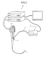
FIG. 2 is a view illustrating a situation in which the optical measurement system according to the embodiment of the present invention is used in an endoscope system. - Hereinafter, preferred embodiments of an optical measurement apparatus and an optical measurement system according to the present invention will be described in detail with reference to the drawings. The present invention is not limited to the embodiments. Further, the same portions will be described by assigning the same reference numerals in the drawings. Furthermore, it needs to be kept in mind that the drawings are schematic, and the relationship between the thickness and the width of each member and the ratio of each member are different from actual members. Still further, there are portions including a different relationship between dimensions and a different ratio even between the drawings.
-
FIG. 1 is a block diagram schematically illustrating a configuration of an optical measurement system according to an embodiment of the present invention. Anoptical measurement system 1 illustrated inFIG. 1 has anoptical measurement apparatus 2 which optically measures a measurement target such as body tissues, which are scatters, and detects the property of the measurement target (characteristics), and ameasurement probe 3 which is used for measurement and which is detachably connected to theoptical measurement apparatus 2 and is inserted into a subject. - First, the
optical measurement apparatus 2 will be described. The living bodyoptical measurement apparatus 2 has apower supply 21, alight source unit 22, aconnection part 23, alight receiving unit 24, aninput unit 25, anoutput unit 26, arecording unit 27 and acontrol unit 28. Thepower supply 21 supplies power to each component of theoptical measurement apparatus 2. - The
light source unit 22 is realized by using, for example, an incoherence light source such as a white LED (Light Emitting Diode), a xenon lamp, a tungsten lamp or a halogen lamp, and one or a plurality of lenses where necessary such as condenser lenses or collimator lenses. Thelight source unit 22 outputs incoherent light which includes at least one spectrum component and which is radiated on a measurement target through theconnection part 23, to themeasurement probe 3. - The
connection part 23 detachably connects aconnector portion 31 of themeasurement probe 3 to theoptical measurement apparatus 2. Theconnection part 23 outputs light emitted from thelight source unit 22, to themeasurement probe 3, and outputs return light of illumination light, which is emitted from themeasurement probe 3 and which is reflected and/or scattered by a measurement target, to thelight receiving unit 24. - Further, the
connection part 23 has aswitch 23a which projects from a surface of theconnection part 23 in which themeasurement probe 3 is attached, and is provided movably with respect to this attaching surface. Theswitch 23a is pushed when themeasurement probe 3 is attached to theconnection part 23, and is pushed in theconnection part 23. When pushed in, theswitch 23a detects that themeasurement probe 3 is attached to theconnection part 23, and causes areset controller 28b to be in an on state which will be described below. - The
light receiving unit 24 receives and measures return light of illumination light which is emitted from themeasurement probe 3 and which is reflected and/or scattered by a measurement target. Thelight receiving unit 24 is realized by using, for example, a plurality of spectrometers and light receiving sensors. More specifically, in thelight receiving unit 24, the number of spectrometers corresponds to the number of light receiving fibers of themeasurement probe 3 which will be described below. Thelight receiving unit 24 measures a spectrum component and an intensity distribution of scattering light incident from themeasurement probe 3, and measures each wavelength. Thelight receiving unit 24 outputs a measurement result to thecontrol unit 28. - The
input unit 25 receives an input of an instruction signal for instructing activation of theoptical measurement apparatus 2 or an instruction signal for instructing other various operations and outputs the instruction signal to thecontrol unit 28. Theinput unit 25 is realized by using, for example, a push-type switch or a touch panel. - The
output unit 26 outputs information related to various processing in theoptical measurement apparatus 2. Further, theoutput unit 26 displays a numerical value such as intensity of light received by the light receiving unit 24 (a characteristic value computed by acomputation unit 28a described below), on a display under control of thecontrol unit 28. Theoutput unit 26 is realized by using, for example, a liquid crystal or organic EL (Electro Luminescence) display and speakers. A configuration may be employed where these numerical values are printed and this printed material is outputted. - The
recording unit 27 is realized by using volatile memory or non-volatile memory, and records various programs for operating the living bodyoptical measurement apparatus 2, and various items of data and various parameters used for optical measurement processing. Therecording unit 27 temporarily records information which is obtained during processing in theoptical measurement apparatus 2. Further, therecording unit 27 associates and records a measurement result obtained by theoptical measurement apparatus 2 and subject information of a subject which is a measurement target (for example, a specimen ID, examination item information and an examination date). Therecording unit 27 may be configured by using, for example, a memory card attached from an outside of theoptical measurement apparatus 2. - The
control unit 28 is configured by using, for example, a CPU (Central Processing Unit). Thecontrol unit 28 controls a processing operation of each unit of the living bodyoptical measurement apparatus 2. Thecontrol unit 28 controls the operation of the living bodyoptical measurement apparatus 2 by, for example, transferring instruction information corresponding to each unit of the living bodyoptical measurement apparatus 2 or data. Thecontrol unit 28 controls the operation of thelight source unit 22, and records the measurement result of thelight receiving unit 24 in therecording unit 27. Thecontrol unit 28 has thecomputation unit 28a and thereset controller 28b. - The
computation unit 28a performs a plurality of computation processing based on the measurement result of thelight receiving unit 24, and computes a characteristic value related to the property of a measurement target. The type of this characteristic value is set according to, for example, an instruction signal received by theinput unit 25. - The
reset controller 28b performs control of deleting and resetting a measurement result in therecording unit 27 in response to an input of a signal from theswitch 23a. Further, thereset controller 28b resets therecording unit 27 when the above-describedswitch 23a is pushed and theswitch 23a causes thereset controller 28b to be in the on state. - Next, the
measurement probe 3 will be described. Themeasurement probe 3 is realized by disposing a plurality of optical fibers inside. More specifically, themeasurement probe 3 is realized by using an illumination fiber which emits illumination light to a measurement target, and a plurality of light receiving fibers on which return light of illumination light reflected and/or scattered by the measurement target is incident at different angles. Themeasurement probe 3 has aconnector portion 31 which is detachably connected to theconnection part 23 of the living bodyoptical measurement apparatus 2, aflexible portion 32 which has flexibility, and atip portion 33 which is provided with an optical element at a tip, and which radiates illumination light supplied from thelight source unit 22 and receives return light from a measurement target. - The
measurement probe 3 has an illumination fiber which radiates illumination light on a measurement target, and light receiving fibers on which return light of the illumination light reflected and/or scattered by the measurement target is incident. Further, the illumination fiber and the light receiving fibers are covered by a glass or resin to prevent damages thereon and fix positions thereof. Furthermore, a covering member adopts a structure in which an outer periphery is covered with a glass or brass to protect the fibers from an external force, and the outer periphery is further covered by a probe outer casing such as SUS. - The illumination fiber is formed by using, for example, a step-index single core fiber. The illumination fiber transmits illumination light outputted from the
light source unit 22, and radiates the illumination light on a measurement target through the optical element. The number of illumination fibers can be adequately changed according to an examination item or a type of a measurement target such as a blood current or a site. - The light receiving fibers are each formed by using, for example, a step-index single core fiber. The light receiving fibers each transmits return light of illumination light which is incident on each tip through the optical element and which is reflected and/or scattered by a measurement target, and outputs the light to the
light receiving unit 24 of the living bodyoptical measurement apparatus 2. The number of light receiving fibers can be adequately changed according to an examination item or a type of a measurement target such as a blood current or a site. - The optical element has a columnar shape, and is formed by using a transmissive glass having a predetermined refractive index. The optical element is formed to fix the distance between the illumination fiber and a measurement target, and radiate light in a state where a spatial coherent length is fixed. Further, the optical element is formed to fix the distances between the light receiving fibers and the measurement target, and stably receive return light at a predetermined scattering angle.
- As illustrated in
FIG. 2 , with theoptical measurement system 1 configured as described above, themeasurement probe 3 is inserted into a subject through atreatment tool channel 111 provided in an endoscope apparatus 110 (endoscope) of anendoscope system 100, the illumination fiber radiates illumination light on a measurement target, and the light receiving fibers each receive return light of illumination light reflected and/or scattered by the measurement target, at different scattering angles and transmit the light to thelight receiving unit 24 of theoptical measurement apparatus 2. Then, thecomputation unit 28a computes a characteristic value of the property of the measurement target based on the measurement result of thelight receiving unit 24. - Meanwhile, when the
measurement probe 3 is replaced, that is, when thenew measurement probe 3 is attached to theoptical measurement apparatus 2, theswitch 23a is pushed. When theswitch 23a is pushed, thereset controller 28b is brought into an on state by theswitch 23a, and deletes a measurement result such as light intensity data recorded in therecording unit 27. - By this means, when the
new measurement probe 3 is attached to perform measurement, a measurement result of a different subject which was previously measured is deleted, so that a measurement result which is currently measured is not associated with a different subject and recorded. - When the
reset controller 28b deletes data in therecording unit 27, setting data related to a processing operation of each unit of theoptical measurement apparatus 2 is preferably left recorded in therecording unit 27 without being deleted. Further, when there is setting data related to themeasurement probe 3, this setting data may be left without being deleted, or the setting data may be deleted and new setting data may be acquired from the attachedmeasurement probe 3. - According to the above-described embodiments of the present invention, the
switch 23a is provided in theconnection part 23 which connects with themeasurement probe 3, when themeasurement probe 3 is attached to theconnection part 23 and theswitch 23a is pushed, theswitch 23a causes thereset controller 28b to be in the on state, and thereset controller 28b which has been brought into the on state deletes and resets a measurement result such as light intensity data recorded in therecording unit 27, so that it is possible to reliably associate subject information with measurement data. - Further, according to the embodiments, the
measurement probe 3 is attachable to and detachable from theoptical measurement apparatus 2, so that themeasurement probe 3 is disposable, themeasurement probe 3 does not need to be sterilized at medical facilities, and themeasurement probe 3 may have comparatively poor durability and, consequently, it is possible to reduce cost of themeasurement probe 3. - Although, when the
switch 23a is pushed, a signal indicating that themeasurement probe 3 is attached is outputted with the above-described embodiments, for example, information unique to this measurement probe 3 (for example, an identification number) may be acquired when themeasurement probe 3 is attached without providing theswitch 23a, and a measurement result in the recording unit may be deleted when this information is inputted in thereset controller 28b. - As described above, an optical measurement apparatus and an optical measurement system according to the present invention are useful in reliably associating subject information with measurement data.
-
- 1
- optical measurement system
- 2
- optical measurement apparatus
- 3
- measurement probe
- 21
- power supply
- 22
- light source unit
- 23
- connection part
- 23a
- switch
- 24
- light receiving unit
- 25
- input unit
- 26
- output unit
- 27
- recording unit
- 28
- control unit
- 28a
- computation unit
- 28b
- reset controller
- 31
- connector portion
- 32
- flexible portion
- 33
- tip portion
- 100
- endoscope system
- 110
- endoscope apparatus
- 111
- treatment tool channel
Claims (3)
- An optical measurement apparatus configured to detachably connect to a measurement probe for performing optical measurement by receiving and outputting light from a tip of the measurement probe, the optical measurement apparatus comprising:a computation unit configured to compute intensity of the light inputted to the measurement probe, and output the intensity as measurement data;a recording unit configured to record the measurement data of at least one subject;a reset controller configured to perform control of deleting the measurement data recorded in the recording unit and resetting the recording unit; anda detector which is provided at a connection part between the optical measurement apparatus and the measurement probe, and which is configured to detect that the measurement probe is attached to the optical measurement apparatus and cause the reset controller to be in an on state according to the detection.
- The optical measurement apparatus according to claim 1, wherein the detector is a switch which is provided movably with respect to a surface of the connection part to which the measurement probe is attached, and, when the measurement probe is attached, the switch is pushed in the connection part and causes the reset controller to be in the on state.
- An optical measurement system comprising:a measurement probe configured to perform optical measurement by receiving and outputting light from a tip of the measurement probe; andan optical measurement apparatus configured to detachably connect to the measurement probe, whereinthe optical measurement apparatus comprises:a computation unit configured to compute intensity of the light inputted to the measurement probe, and output the intensity as measurement data;a recording unit configured to record the measurement data of at least one subject;a reset controller configured to perform control of deleting the measurement data recorded in the recording unit and resetting the recording unit; anda detector which is provided at a connection part between the optical measurement apparatus and the measurement probe, and which is configured to detect that the measurement probe is attached to the optical measurement apparatus and cause the reset controller to be in an on state according to the detection.
Applications Claiming Priority (2)
| Application Number | Priority Date | Filing Date | Title |
|---|---|---|---|
| US201261681386P | 2012-08-09 | 2012-08-09 | |
| PCT/JP2013/068649 WO2014024614A1 (en) | 2012-08-09 | 2013-07-08 | Optical measurement device and optical measurement system |
Publications (2)
| Publication Number | Publication Date |
|---|---|
| EP2884267A1 true EP2884267A1 (en) | 2015-06-17 |
| EP2884267A4 EP2884267A4 (en) | 2016-03-30 |
Family
ID=50067854
Family Applications (1)
| Application Number | Title | Priority Date | Filing Date |
|---|---|---|---|
| EP13827902.1A Withdrawn EP2884267A4 (en) | 2012-08-09 | 2013-07-08 | Optical measurement device and optical measurement system |
Country Status (5)
| Country | Link |
|---|---|
| US (1) | US8842285B2 (en) |
| EP (1) | EP2884267A4 (en) |
| JP (1) | JP5469291B1 (en) |
| CN (1) | CN103857999B (en) |
| WO (1) | WO2014024614A1 (en) |
Families Citing this family (1)
| Publication number | Priority date | Publication date | Assignee | Title |
|---|---|---|---|---|
| EP3261692B1 (en) * | 2015-02-27 | 2020-08-19 | Novo Nordisk A/S | Accessory device with mounting safety feature |
Family Cites Families (18)
| Publication number | Priority date | Publication date | Assignee | Title |
|---|---|---|---|---|
| US4600923A (en) * | 1984-05-04 | 1986-07-15 | American Meter Company | Remote meter display unit |
| DE3543096A1 (en) * | 1984-12-05 | 1986-06-05 | Olympus Optical Co., Ltd., Tokio/Tokyo | DEVICE FOR THE CRUSHING OF STONES, LIKE KIDNEY AND GALLET STONES OR THE LIKE |
| US5219345A (en) * | 1990-03-30 | 1993-06-15 | Health Research, Inc. | Backscatter monitoring system |
| US6573984B2 (en) * | 1998-06-30 | 2003-06-03 | Lj Laboratories Llc | Apparatus and method for measuring optical characteristics of teeth |
| US6308089B1 (en) * | 1999-04-14 | 2001-10-23 | O.B. Scientific, Inc. | Limited use medical probe |
| JP2002291764A (en) | 2001-03-29 | 2002-10-08 | Nidek Co Ltd | Laser therapeutic device |
| FR2854281B1 (en) * | 2003-04-28 | 2005-06-17 | Valeo Equip Electr Moteur | ELECTRICAL CONNECTOR FOR CONNECTING THEM BETWEEN THE TWO ELECTRONIC OVERLAPPED CIRCUITS AND ITS MOUNTING METHOD |
| JP4282436B2 (en) * | 2003-10-29 | 2009-06-24 | オリンパス株式会社 | Stereoscopic observation device |
| KR20060133557A (en) * | 2004-01-08 | 2006-12-26 | 신세다이 가부시끼가이샤 | Adapters, cartridges, computer systems, and entertainment systems |
| JP2006006515A (en) * | 2004-06-24 | 2006-01-12 | Olympus Corp | Electronic endoscope device |
| JP4547243B2 (en) | 2004-12-08 | 2010-09-22 | オリンパス株式会社 | Endoscope system |
| US20060185877A1 (en) * | 2005-02-18 | 2006-08-24 | Aviv Soffer | Wall mounted system with insertable computing apparatus |
| JP4767649B2 (en) * | 2005-10-14 | 2011-09-07 | 富士フイルム株式会社 | Endoscope device |
| JP2009530063A (en) * | 2006-03-22 | 2009-08-27 | コンメッド エンドスコーピック テクノロジーズ インコーポレーテッド | Method and apparatus for measuring movement of long instruments |
| JP2008029521A (en) * | 2006-07-27 | 2008-02-14 | Olympus Medical Systems Corp | Endoscope system |
| JP5226195B2 (en) * | 2006-07-28 | 2013-07-03 | オリンパスメディカルシステムズ株式会社 | Endoscope apparatus and method for operating endoscope apparatus |
| JP2008089416A (en) * | 2006-10-02 | 2008-04-17 | Nikon Corp | Inspection illumination device and image sensor inspection device |
| JP2010286765A (en) * | 2009-06-15 | 2010-12-24 | Olympus Corp | Endoscopic device and program |
-
2013
- 2013-07-08 CN CN201380003356.4A patent/CN103857999B/en not_active Expired - Fee Related
- 2013-07-08 WO PCT/JP2013/068649 patent/WO2014024614A1/en not_active Ceased
- 2013-07-08 JP JP2013552766A patent/JP5469291B1/en not_active Expired - Fee Related
- 2013-07-08 EP EP13827902.1A patent/EP2884267A4/en not_active Withdrawn
- 2013-11-20 US US14/085,132 patent/US8842285B2/en not_active Expired - Fee Related
Also Published As
| Publication number | Publication date |
|---|---|
| JPWO2014024614A1 (en) | 2016-07-25 |
| EP2884267A4 (en) | 2016-03-30 |
| CN103857999A (en) | 2014-06-11 |
| CN103857999B (en) | 2015-12-02 |
| WO2014024614A1 (en) | 2014-02-13 |
| US20140146320A1 (en) | 2014-05-29 |
| JP5469291B1 (en) | 2014-04-16 |
| US8842285B2 (en) | 2014-09-23 |
Similar Documents
| Publication | Publication Date | Title |
|---|---|---|
| JP2019510203A5 (en) | ||
| EP2653854B1 (en) | Optical measuring system and calibration method | |
| US9014517B2 (en) | Fiber unit | |
| EP2526852B1 (en) | Optical measurement device, optical measurement system, and module for correction | |
| US8717571B2 (en) | Optical measurement apparatus and optical measurement system | |
| EP2740399A1 (en) | Measurement probe, bio-optical measurement apparatus and bio-optical measurement system | |
| US9211053B2 (en) | Medical apparatus, disposable medical device, and medical system | |
| EP2759247A1 (en) | Optical measurement apparatus and calibration method | |
| EP2884267A1 (en) | Optical measurement device and optical measurement system | |
| US20160206210A1 (en) | Optical measurement apparatus | |
| US20160183805A1 (en) | Calibrator and calibration apparatus | |
| US10682043B2 (en) | Measurement probe and bio-optical measurement system with contact detection | |
| US20140046135A1 (en) | Measurement probe | |
| JP2020054554A (en) | Sensor probe and sensor system | |
| EP2813171A1 (en) | Bio-optical measurement device and measurement probe | |
| EP2856921A1 (en) | Measuring probe | |
| JP5763285B1 (en) | Optical measuring device | |
| WO2015174543A1 (en) | Measurement probe and optical measurement system | |
| WO2013140690A1 (en) | Measurement probe and bio-optical measurement system | |
| WO2015033914A1 (en) | Calibration module |
Legal Events
| Date | Code | Title | Description |
|---|---|---|---|
| PUAI | Public reference made under article 153(3) epc to a published international application that has entered the european phase |
Free format text: ORIGINAL CODE: 0009012 |
|
| 17P | Request for examination filed |
Effective date: 20150224 |
|
| AK | Designated contracting states |
Kind code of ref document: A1 Designated state(s): AL AT BE BG CH CY CZ DE DK EE ES FI FR GB GR HR HU IE IS IT LI LT LU LV MC MK MT NL NO PL PT RO RS SE SI SK SM TR |
|
| AX | Request for extension of the european patent |
Extension state: BA ME |
|
| RAP1 | Party data changed (applicant data changed or rights of an application transferred) |
Owner name: OLYMPUS CORPORATION |
|
| DAX | Request for extension of the european patent (deleted) | ||
| RA4 | Supplementary search report drawn up and despatched (corrected) |
Effective date: 20160225 |
|
| RIC1 | Information provided on ipc code assigned before grant |
Ipc: A61B 1/00 20060101ALI20160219BHEP Ipc: G01N 21/84 20060101AFI20160219BHEP |
|
| STAA | Information on the status of an ep patent application or granted ep patent |
Free format text: STATUS: THE APPLICATION HAS BEEN WITHDRAWN |
|
| 18W | Application withdrawn |
Effective date: 20160615 |