EP2884247A1 - Spectromètre pour générer un spectre à deux dimensions - Google Patents
Spectromètre pour générer un spectre à deux dimensions Download PDFInfo
- Publication number
- EP2884247A1 EP2884247A1 EP13197479.2A EP13197479A EP2884247A1 EP 2884247 A1 EP2884247 A1 EP 2884247A1 EP 13197479 A EP13197479 A EP 13197479A EP 2884247 A1 EP2884247 A1 EP 2884247A1
- Authority
- EP
- European Patent Office
- Prior art keywords
- main
- spectrometer
- main grating
- grating
- image plane
- Prior art date
- Legal status (The legal status is an assumption and is not a legal conclusion. Google has not performed a legal analysis and makes no representation as to the accuracy of the status listed.)
- Withdrawn
Links
- 238000001228 spectrum Methods 0.000 title claims abstract description 51
- 238000003384 imaging method Methods 0.000 claims abstract description 78
- 230000005855 radiation Effects 0.000 claims abstract description 57
- 239000006185 dispersion Substances 0.000 claims abstract description 55
- 230000003287 optical effect Effects 0.000 claims abstract description 44
- 238000000034 method Methods 0.000 claims abstract description 28
- 230000004075 alteration Effects 0.000 claims abstract description 19
- 230000008859 change Effects 0.000 claims description 2
- 230000003595 spectral effect Effects 0.000 description 11
- 230000008901 benefit Effects 0.000 description 8
- 238000009826 distribution Methods 0.000 description 6
- 238000004519 manufacturing process Methods 0.000 description 4
- 230000001419 dependent effect Effects 0.000 description 3
- 230000000694 effects Effects 0.000 description 2
- 230000008569 process Effects 0.000 description 2
- 238000004458 analytical method Methods 0.000 description 1
- 230000005670 electromagnetic radiation Effects 0.000 description 1
- 238000012986 modification Methods 0.000 description 1
- 230000004048 modification Effects 0.000 description 1
- 239000000523 sample Substances 0.000 description 1
- 238000000926 separation method Methods 0.000 description 1
- 238000007493 shaping process Methods 0.000 description 1
- 238000003860 storage Methods 0.000 description 1
- 230000001052 transient effect Effects 0.000 description 1
Images

Classifications
-
- G—PHYSICS
- G01—MEASURING; TESTING
- G01J—MEASUREMENT OF INTENSITY, VELOCITY, SPECTRAL CONTENT, POLARISATION, PHASE OR PULSE CHARACTERISTICS OF INFRARED, VISIBLE OR ULTRAVIOLET LIGHT; COLORIMETRY; RADIATION PYROMETRY
- G01J3/00—Spectrometry; Spectrophotometry; Monochromators; Measuring colours
- G01J3/28—Investigating the spectrum
- G01J3/2823—Imaging spectrometer
-
- G—PHYSICS
- G01—MEASURING; TESTING
- G01J—MEASUREMENT OF INTENSITY, VELOCITY, SPECTRAL CONTENT, POLARISATION, PHASE OR PULSE CHARACTERISTICS OF INFRARED, VISIBLE OR ULTRAVIOLET LIGHT; COLORIMETRY; RADIATION PYROMETRY
- G01J3/00—Spectrometry; Spectrophotometry; Monochromators; Measuring colours
- G01J3/02—Details
- G01J3/0205—Optical elements not provided otherwise, e.g. optical manifolds, diffusers, windows
- G01J3/0208—Optical elements not provided otherwise, e.g. optical manifolds, diffusers, windows using focussing or collimating elements, e.g. lenses or mirrors; performing aberration correction
-
- G—PHYSICS
- G01—MEASURING; TESTING
- G01J—MEASUREMENT OF INTENSITY, VELOCITY, SPECTRAL CONTENT, POLARISATION, PHASE OR PULSE CHARACTERISTICS OF INFRARED, VISIBLE OR ULTRAVIOLET LIGHT; COLORIMETRY; RADIATION PYROMETRY
- G01J3/00—Spectrometry; Spectrophotometry; Monochromators; Measuring colours
- G01J3/02—Details
- G01J3/0205—Optical elements not provided otherwise, e.g. optical manifolds, diffusers, windows
- G01J3/021—Optical elements not provided otherwise, e.g. optical manifolds, diffusers, windows using plane or convex mirrors, parallel phase plates, or particular reflectors
-
- G—PHYSICS
- G01—MEASURING; TESTING
- G01J—MEASUREMENT OF INTENSITY, VELOCITY, SPECTRAL CONTENT, POLARISATION, PHASE OR PULSE CHARACTERISTICS OF INFRARED, VISIBLE OR ULTRAVIOLET LIGHT; COLORIMETRY; RADIATION PYROMETRY
- G01J3/00—Spectrometry; Spectrophotometry; Monochromators; Measuring colours
- G01J3/02—Details
- G01J3/0256—Compact construction
-
- G—PHYSICS
- G01—MEASURING; TESTING
- G01J—MEASUREMENT OF INTENSITY, VELOCITY, SPECTRAL CONTENT, POLARISATION, PHASE OR PULSE CHARACTERISTICS OF INFRARED, VISIBLE OR ULTRAVIOLET LIGHT; COLORIMETRY; RADIATION PYROMETRY
- G01J3/00—Spectrometry; Spectrophotometry; Monochromators; Measuring colours
- G01J3/02—Details
- G01J3/0291—Housings; Spectrometer accessories; Spatial arrangement of elements, e.g. folded path arrangements
-
- G—PHYSICS
- G01—MEASURING; TESTING
- G01J—MEASUREMENT OF INTENSITY, VELOCITY, SPECTRAL CONTENT, POLARISATION, PHASE OR PULSE CHARACTERISTICS OF INFRARED, VISIBLE OR ULTRAVIOLET LIGHT; COLORIMETRY; RADIATION PYROMETRY
- G01J3/00—Spectrometry; Spectrophotometry; Monochromators; Measuring colours
- G01J3/12—Generating the spectrum; Monochromators
- G01J3/18—Generating the spectrum; Monochromators using diffraction elements, e.g. grating
- G01J3/1809—Echelle gratings
Definitions
- the present disclosure relates to a spectrometer for generating a two dimensional spectrum.
- a spectrometer is an instrument used to probe a property of light as a function of its portion of the electromagnetic spectrum, e.g. for spectrally resolving the light.
- the term 'light' or 'radiation' as used herein includes all forms of electromagnetic radiation such as visible, infrared and/or ultraviolet radiation.
- a spectrometer comprises reflective and/or refractive optics for guiding and shaping the light as well as a dispersion element such as a grating and/or prism for refracting, diffracting and/or dispersing the light in a wavelength dependent angle.
- a dispersion element such as a grating and/or prism for refracting, diffracting and/or dispersing the light in a wavelength dependent angle.
- different spectral components of the light can be imaged at different locations along a spectral axis in an imaging plane of the spectrometer.
- a sensor can be arranged for detecting spectral components of the light in the
- a typical spectrometer In a typical spectrometer, light is dispersed along a single spectral axis.
- a disadvantage of such a spectrometer can be that for measuring a large bandwidth of light with a high resolution, a long (one dimensional) detector is needed to capture the spectral image.
- This can be alleviated by providing a spectrometer that generates a two dimensional spectrum, i.e. projects a two dimensional image wherein light is dispersed along two spectral axes. In this way the spectral image and corresponding detector can be more compact for a relatively high bandwidth and resolution.
- EP1754032 B1 described a spectrometer assembly with a spectrometer for generating a radiation spectrum in a first wavelength range of a light source on a detector.
- the spectrometer comprises an Echelle grating for spectrally dispersing radiation entering the spectrometer assembly in a main dispersion direction.
- the spectrometer further comprises a dispersion element for separating the orders by means of spectrally dispersing the radiation in a lateral dispersion direction forming an angle with the main dispersion direction of the Echelle grating.
- the grating and dispersion element are adapted to generate a two dimensional spectrum with a plurality of separated orders.
- the spectrometer further comprises an imaging optical system for imaging the radiation entering through an entrance slit into the spectrometer assembly in an imaging plane.
- the spectrometer further comprises a detector array with a two-dimensional arrangement of a plurality of detector elements in the imaging plane.
- a first aspect of the present disclosure provides a spectrometer for generating a two dimensional spectrum, the spectrometer comprising a main grating arranged for spectrally dispersing radiation entering the spectrometer along a main dispersion direction; a cross dispersion element arranged for separating diffraction orders of the main grating by means of spectrally dispersing the radiation in a cross dispersion direction forming an angle with the main dispersion direction of the main grating adapted to generate the two dimensional spectrum with a plurality of separated orders; an imaging mirror arranged for reflecting and focussing dispersed radiation from the main grating towards an image plane for imaging the two dimensional spectrum onto the image plane; and a correction lens arranged for correcting optical aberrations in the imaging of the two dimensional spectrum in the image plane; wherein the imaging mirror and the correction lens have a coinciding axis of cylindrical symmetry.
- the spectrum can be imaged in a more compact way.
- the spectrometer design can be relatively compact.
- the combined dispersion/refraction caused by the main grating and cross dispersion element may result in an angular distribution of radiation impinging the imaging mirror which can lead to optical aberrations in the image plane.
- a correction lens By introducing a correction lens, such aberrations can be at least partially counteracted.
- the ability of the correction lens is sensitive to its exact placement with respect to the other optical elements, in particular the imaging mirror. It is found that inexact positioning of the correction lens during manufacturing can lead to deteriorated properties of the spectrometer.
- optical components can become relatively shifted e.g. due to thermal or other stress, which can also deteriorate performance.
- the inventors find that the conventional spectrometer design for generating two dimensional spectra can be improved by introducing symmetries between specific optical elements that are conventionally not considered.
- the imaging mirror and correction lens can be placed such that their axis of cylindrical symmetry coincides, relative placement accuracy of these elements can be improved both during manufacturing and active use of the spectrometer.
- the symmetric arrangement can allow for greater tolerances to e.g. (thermal) shifting and expansion of components.
- the imaging mirror and correction lens can be more easily centred with respect to each other e.g. by mechanical means, for example a common cylindrical housing.
- the components can be placed from one side against a common contact surface. Especially if the components have the same size, they can be positioned with a flush contact surface from one side. In this way, there can also be a simple yet accurate enclosure of the optical components. Accordingly, by these and other aspects of the present disclosure an improved spectrometer for generating a two dimensional spectrum, in particular with regards to manufacturability and stability, can be provided.
- the image of the two dimensional spectrum in the image plane can be flattened.
- a flat detector array can be used to capture the spectral image.
- a detector array with a two-dimensional flat arrangement of a plurality of detector elements can be placed in the imaging plane to register the spectral image.
- Such a typical flat detector array can be especially useful when the image has been flattened.
- the field flattening lens also other correction lenses can be used, e.g.
- each has a coinciding axis of cylindrical symmetry with the imaging mirror, e.g. for similar reasons as noted above.
- a correction lens can be placed between the main grating and the imaging mirror to be traversed twice.
- the main grating By arranging the main grating partially in between the correction lens and the imaging mirror, an angle of incidence of the dispersed radiation onto the cylindrically symmetric imaging mirror can be lowered. By lowering the angle of incidence, optical aberrations of the imaging can be lowered. The more the grating can be positioned in between the correction lens and the imaging mirror, the lower the angle of incidence, and the lower the optical aberrations, particularly for a spherical mirror. On the other hand, the grating can block part of the light between the imaging mirror and correction lens. As a compromise, the main grating can be inserted about half way in between the imaging mirror and correction lens.
- an angle of incidence is preferably below 40 degrees, more preferably below 30 degrees, even more preferable below 20 degrees, e.g. between 5 and 30 degrees.
- the main grating By arranging the main grating in the middle of the axis of cylindrical symmetry along the main dispersion direction, a relatively wide range of diffraction angles can be imaged by the imaging mirror. This may contribute to an improved efficiency of the spectrometer. For example, when light enters the spectrometer beyond a certain acceptance angle and some wavelengths of that light are refracted outside the area of the imaging mirror, efficiency of the spectrometer can be lower.
- the main grating By arranging the main grating with its surface perpendicular to the axis of cylindrical symmetry, the spectrometer can be relatively insensitive to rotation of the grating. Furthermore, placement accuracy of the grating during manufacturing can be improved.
- relative ease of placement combined with the symmetrical design can contribute to the option of easily replacing the grating, e.g. if it is desired to use the spectrometer for a different wavelength range and/or resolution by using another grating having a different line density and/or groove profile.
- the main grating is adapted for projecting relatively low diffraction orders onto the image plane.
- diffraction orders may depend e.g. on the line density of the grating and/or the geometry of the incident radiation.
- the main grating has a line density of at least 150 lines per millimetre, preferably at least 300 lines per millimetre.
- relatively low incidence angles are used as detailed above.
- a prism as the cross dispersion element provides a relatively efficient and simple way of cross-dispersing the radiation and separating otherwise overlapping orders of the diffraction grating. By having the radiation traverse the prism only once losses at the interfaces can be minimized. Furthermore, it allows the prism to be placed outside the path between the grating and imaging mirror thus maintaining the symmetry of the system.
- other cross dispersion elements can be used, e.g. a cross dispersion grating.
- a second aspect of the present disclosure provides a method for generating a two dimensional spectrum, the method comprising using a main grating for spectrally dispersing radiation along a main dispersion direction; using a cross dispersion element for separating diffraction orders of the main grating by means of spectrally dispersing the radiation in a cross dispersion direction forming an angle with the main dispersion direction of the main grating adapted to generate the two dimensional spectrum with a plurality of separated orders; using an imaging mirror for reflecting and focussing dispersed radiation from the main grating towards an image plane for imaging the two dimensional spectrum onto the image plane; and using a correction lens for correcting optical aberrations in the imaging of the two dimensional spectrum in the image plane; wherein the imaging mirror and the correction lens have a coinciding axis of cylindrical symmetry.
- the method can provide similar advantages as the spectrometer.
- an object When an object has cylindrical symmetry, this means the object can be rotated around an axis by any angle without affecting its appearance.
- the axis around which the object is cylindrically symmetric is referred to as the axis of cylindrical symmetry.
- a lens or mirror When a lens or mirror is cylindrically symmetric this means it can be arbitrarily rotated around its axis of cylindrical symmetry without affecting its optical function or performance.
- An optical aberration is a departure of the performance of an optical system from the predictions of paraxial optics.
- monochromatic aberrations can be caused by the geometry of the lens/mirror and can occur both when light is reflected and when it is refracted.
- chromatic aberrations can be caused by the variation of a lens's refractive index with wavelength.
- Some aberration can be corrected by introducing further optical element, e.g. 'correction lenses' that at least partially counteract the effect of the aberration.
- Petzval field curvature describes the optical aberration in which a flat object normal to the optical axis cannot be brought into focus on a flat image plane.
- a field flattening lens counteracts the Petzval field curvature of an optical system by shifting the focal points of the Petzval surface to lie in the same plane thereby countering the field-angle dependence of the focal length of the system.
- a typical flat sensor array can be used in the image plane to correctly register said image.
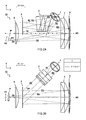
- FIG 1A shows a perspective view of an embodiment of a spectrometer 10.
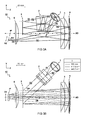
- FIGs 2 and 3 show respective side (XY) and top (YZ) view of the spectrometer 10.
- the figures include simulated optical paths of radiation R0-R5 traversing the spectrometer 10.
- FIG 1B shows an example two dimensional spectrum recorded at the image plane IP of the spectrometer 10.
- the spectrometer 10 is arranged for generating a two dimensional spectrum S.
- the spectrometer 10 comprises a main grating 3 arranged for spectrally dispersing radiation entering the spectrometer along a main dispersion direction A1.
- the spectrometer 10 comprises a cross dispersion element 2 (e.g. prism) arranged for separating diffraction orders Ox of the main grating 3.
- the orders can e.g. be separated by means of spectrally dispersing the radiation in a cross dispersion direction A2 forming an angle with the main dispersion direction A1 of the main grating 3. In this way the two dimensional spectrum S can be generated with a plurality of separated orders Ox.
- the angle between the dispersion directions A1 and A2 is preferably close to ninety degrees, i.e. transverse to one another, to have a good separation of the diffraction orders.
- the cross dispersion element 2 is preferably placed in a light path R1-R2 before the grating 3.
- the light beam R2 impinging the cross dispersion element 2 is collimated, e.g. by collimator R1..
- the spectrometer 10 comprises an imaging mirror 4 arranged for reflecting and focussing dispersed radiation R3 from the main grating 3 towards an image plane IP for imaging the two dimensional spectrum S onto the image plane IP.
- the imaging of spectrally dispersed radiation involves the converting of an angular distribution into a corresponding (in-focus) spatial distribution in the image plane IP, where a detector (not shown) can be placed to record the spectrum by its spatial distribution. While the imaging of the angularly dispersed radiation is mainly effected by the focussing mirror 4, also other optical components can play a role in determining the imaging position, focus and quality.
- the spectrometer 10 comprises a correction lens 6 arranged for correcting optical aberrations in the imaging of the two dimensional spectrum S in the image plane IP.
- the imaging mirror 4 and the correction lens 6 are both cylindrically symmetric.
- rotational shifts of these components do not affect their optical performance.
- the imaging mirror 4 and the correction lens 6 have a coinciding axis of cylindrical symmetry AS e.g. to better compensate relative shift in the system
- the correction lens 6 is arranged in an optical path between the main grating 3 and the image plane IP. In a further embodiment, the correction lens 6 is arranged in an optical path between the imaging mirror 4 and the image plane IP. Accordingly, the correction lens 6 is arranged for correcting radiation R4 reflected off the imaging mirror 4 towards the image plane IP.
- the main grating 3 is arranged partially in between the correction lens 6 and the imaging mirror 4. In other words, at least some paths between parts of the imaging mirror 4 and correction lens 6 are blocked by the main grating 3 therein between.
- the main grating 3 is arranged in the middle of the axis of cylindrical symmetry AS along the main dispersion direction A1, e.g. as shown in FIGs 2B and 3B . It may be surprising that the grating 3 is placed partially in between the optical components 4 and 6 which position may be expected to block optical paths between these components.
- the path of the radiation follows a zigzag direction along the cross dispersion direction A2 which allows the radiation R4, reflected off the imaging mirror 4, to pass the grating 3 and be projected in the image plane IP.
- a maximum angle can be provided for the diffraction along the main dispersion direction A1 in either positive or negative diffraction orders.
- the efficiency and/or acceptance angle of the spectrometer can be improved, e.g. providing an F-number of f/3.3 or better, e.g. in one embodiment the present design can provide an F-number of f/2 for a slit dimension of 25 ⁇ m.
- the main grating 3 is arranged with its surface 3s perpendicular to the axis of cylindrical symmetry AS. This perpendicular arrangement allows a symmetric distribution of positive and negative diffraction orders to be handled by the imaging mirror 4, further improving efficiency.
- the correction lens 6 is a field flattening lens arranged for flattening the image of the two dimensional spectrum S in the image plane IP.
- the field flattening lens can e.g. correct focal distances to produce a planar image of the spectrum.
- the lens may be considered part of the imaging system, e.g. providing a desired optical power to said system.
- a normal vector NV of the image plane IP is at an angle with respect to the axis of cylindrical symmetry AS. In other words, the image plane IP need not be perpendicular to the axis of cylindrical symmetry AS.
- an optical path of the radiation R3,R4 traverses a correction lens 5 once between the main grating 3 and the imaging mirror 4 and once between the imaging mirror 4 and the image plane IP.
- a correction lens twice By using a correction lens twice, its optical power can be enhanced. Embodiments without lens 5 are also possible.
- the spectrometer comprises a detector array with a two-dimensional flat arrangement of a plurality of detector elements in the imaging plane IP. It will be appreciated that a flat detector array can be relatively easy to manufacture e.g. compared to a curved detector array.
- a processor (not shown) is comprised in the instrument to control and read out other components such as the detector array and/or analyse the spectrum.
- the spectrometer 10 comprises a collimating optics 1, arranged for collimating incoming radiation R0.
- the radiation is collimated when traversing the cross dispersion element 2.
- the cross dispersion element 2 comprises a prism.
- the prism is traversed only once by an optical path of the radiation R1,R2.
- the cross dispersion element 2 is placed in a separate arm of the optical setup that guides incoming light towards the main grating 3.
- the spectrometer 10 comprises a first correction lens 6 and a second correction lens 5, wherein both correction lenses 5,6 have a coinciding axis of cylindrical symmetry AS with the imaging mirror 4.
- the first correction lens 6 is arranged (as viewed along the axis of cylindrical symmetry AS) between the grating 3 and the image plane IP while the second correction lens 5 is arranged between the main grating 3 and imaging mirror 4 (viewed along the axis AS).
- the correction lenses may contribute to correcting, e.g. flattening, the image as well as displacing a position of the image plane IP.
- a single correction lens can be used.
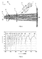
- FIG 4 shows a top view of a second embodiment wherein a single correction lens 6' is used.
- the correction lens 6' has a coinciding axis of cylindrical symmetry AS with the imaging mirror 4.
- the main grating 3 is arranged to have radiation R2 impinge the main grating 3 with an angle of incidence ⁇ 2 below 30 degrees in the cross dispersion direction A2, e.g. as illustrated in FIGs 2A and 3A , preferably even lower, e.g. between 10 and 20 degrees.
- the angle of incidence ⁇ 2 can determine a zigzag angle of the radiation path R2, R3,R4 which angle is preferably as low as possible for having close to normal incidence on the imaging mirror 4 without the back reflected radiation R4 clipping on the main grating 3.
- the main grating 3 is arranged to have radiation R2 impinge the main grating 3 with an angle of incidence ⁇ 1 below 50 degrees in the main dispersion direction A1, e.g. as illustrated in FIGs 2B and 3B , preferably even lower, e.g. between 10 and 40 degrees.
- the lower angle of incidence ⁇ 1 in the main dispersion direction A1 may correspond to lower diffraction orders being used.
- the main grating 3 has a line density of at least 150 lines per millimetre, preferably at least 300 lines per millimetre.
- the main grating 3 is adapted for projecting diffraction orders Ox below order fifteen onto the image plane IP.
- FIG 5 shows a graph of a typical grating efficiency n as a function of wavelength ⁇ for different diffraction orders 06 (order 6) ... O18 (order 18).
- n typically cover a larger wavelength range than higher diffraction orders and may provide a more sensitive system. Accordingly, it is found advantageous to use the lower diffraction orders, to simplify reconstruction of the spectral features from the two dimensional spectral image.
- One aspect of the present disclosure provides a method for generating a two dimensional spectrum S.
- the method comprises using a main grating 3 for spectrally dispersing radiation along a main dispersion direction A1.
- the method further comprises using a cross dispersion element 2 for separating diffraction orders Ox of the main grating 3 by means of spectrally dispersing the radiation in a cross dispersion direction A2 forming an angle with the main dispersion direction A1 of the main grating 3 adapted to generate the two dimensional spectrum S with a plurality of separated orders Ox.
- the method further comprises using an imaging mirror 4 for reflecting and focussing dispersed radiation R3 from the main grating 3 towards an image plane IP for imaging the two dimensional spectrum S onto the image plane IP.
- the method further comprises using a correction lens 6 for correcting optical aberrations in the imaging of the two dimensional spectrum S in the image plane IP.
- the imaging mirror 4 and the correction lens 6 have a coinciding axis of cylindrical symmetry
- the method comprises measuring a first two dimensional spectrum S using a first main grating; replacing the first main grating with a second main grating while keeping the imaging mirror 4, correction lens 6, and image plane IP unchanged; and measuring a second two dimensional spectrum using the second main grating.
- the presently disclosed spectrometer is particularly suitable to allow easy replacement of the grating, e.g. if measuring at another wavelength range is desired using a second main grating having a different line density than the first main grating.
- all components are kept at the same position and a change in bandwidth and resolution is effected by only replacing the grating. This can provide advantages in terms of manufacturability and use.
- radiation R0 from an origin is collimated and reflected by mirror 1 as radiation R1 impinging the prism 2.
- the radiation R2 While traversing the prism 2, the radiation R2 is given a small wavelength dependent angular distribution in the cross dispersion direction A2.
- Said radiation R2 impinges the grating 3 under an angle of incidence ⁇ 1, ⁇ 2 and is refracted in a wavelength dependent direction as radiation R3 towards the focusing mirror 4.
- the radiation R3 passes through a lens 5 before and after impinging the mirror 4.
- the reflected radiation R4 is focussed by the combined optics 4 and 5 as well as additional lens 6 in the imaging plane IP.
- the embodiment of FIG 4 is similar though without the second lens 5.
Priority Applications (4)
| Application Number | Priority Date | Filing Date | Title |
|---|---|---|---|
| EP13197479.2A EP2884247A1 (fr) | 2013-12-16 | 2013-12-16 | Spectromètre pour générer un spectre à deux dimensions |
| US15/104,755 US10288481B2 (en) | 2013-12-16 | 2014-12-16 | Spectrometer for generating a two dimensional spectrum |
| EP14825460.0A EP3084373B1 (fr) | 2013-12-16 | 2014-12-16 | Spectromètre pour générer un spectre à deux dimensions |
| PCT/NL2014/050865 WO2015093944A1 (fr) | 2013-12-16 | 2014-12-16 | Spectromètre générant un spectre bidimensionnel |
Applications Claiming Priority (1)
| Application Number | Priority Date | Filing Date | Title |
|---|---|---|---|
| EP13197479.2A EP2884247A1 (fr) | 2013-12-16 | 2013-12-16 | Spectromètre pour générer un spectre à deux dimensions |
Publications (1)
| Publication Number | Publication Date |
|---|---|
| EP2884247A1 true EP2884247A1 (fr) | 2015-06-17 |
Family
ID=49759218
Family Applications (2)
| Application Number | Title | Priority Date | Filing Date |
|---|---|---|---|
| EP13197479.2A Withdrawn EP2884247A1 (fr) | 2013-12-16 | 2013-12-16 | Spectromètre pour générer un spectre à deux dimensions |
| EP14825460.0A Active EP3084373B1 (fr) | 2013-12-16 | 2014-12-16 | Spectromètre pour générer un spectre à deux dimensions |
Family Applications After (1)
| Application Number | Title | Priority Date | Filing Date |
|---|---|---|---|
| EP14825460.0A Active EP3084373B1 (fr) | 2013-12-16 | 2014-12-16 | Spectromètre pour générer un spectre à deux dimensions |
Country Status (3)
| Country | Link |
|---|---|
| US (1) | US10288481B2 (fr) |
| EP (2) | EP2884247A1 (fr) |
| WO (1) | WO2015093944A1 (fr) |
Cited By (3)
| Publication number | Priority date | Publication date | Assignee | Title |
|---|---|---|---|---|
| WO2018138609A1 (fr) * | 2017-01-25 | 2018-08-02 | Rathore Shubham | Spectromètre et procédé de mesure de caractéristiques spectrales avec celui-ci |
| CN110553733A (zh) * | 2018-06-04 | 2019-12-10 | 耶拿分析仪器股份公司 | 光谱仪设备 |
| WO2020081319A1 (fr) * | 2018-10-17 | 2020-04-23 | Rigaku Analytical Devices, Inc. | Spectromètre bidimensionnel compact |
Families Citing this family (6)
| Publication number | Priority date | Publication date | Assignee | Title |
|---|---|---|---|---|
| US10234694B2 (en) | 2016-07-15 | 2019-03-19 | Canon U.S.A., Inc. | Spectrally encoded probes |
| US11067441B2 (en) | 2017-02-08 | 2021-07-20 | Nederlandse Organisatie Voor Toegepast-Natuurwetenschappelijk Onderzoek Tno | Correction of curved projection of a spectrometer slit line |
| EP3401656A1 (fr) * | 2017-05-11 | 2018-11-14 | Nederlandse Organisatie voor toegepast- natuurwetenschappelijk onderzoek TNO | Correction de projection incurvée d'une ligne à fente de spectromètre |
| DE102019113478A1 (de) * | 2019-05-21 | 2020-11-26 | Analytik Jena Ag | Spektrometeranordnung |
| CN112539836B (zh) * | 2020-11-20 | 2022-03-25 | 中国科学院西安光学精密机械研究所 | 基于前臂补偿和平面光栅的光谱成像系统 |
| CN115790850A (zh) * | 2023-02-09 | 2023-03-14 | 浙江大学 | 一种高动态范围高分辨率分画幅快照式高光谱成像系统 |
Citations (11)
| Publication number | Priority date | Publication date | Assignee | Title |
|---|---|---|---|---|
| US3658423A (en) * | 1971-01-14 | 1972-04-25 | Spectrametrics Inc | Echelle spectrometer |
| US3922089A (en) * | 1972-03-17 | 1975-11-25 | Nils Allan Danielsson | Apparatus and method for the uniform separation of spectral orders |
| US4995721A (en) * | 1990-03-05 | 1991-02-26 | Imo Industries, Inc. | Two-dimensional spectrometer |
| US5018856A (en) * | 1989-10-30 | 1991-05-28 | The United States Of America As Represented By The Secretary Of Agriculture | Continuum source atomic absorption spectrometry |
| US5565983A (en) * | 1995-05-26 | 1996-10-15 | The Perkin-Elmer Corporation | Optical spectrometer for detecting spectra in separate ranges |
| US20060038997A1 (en) * | 2004-08-19 | 2006-02-23 | Julian Jason P | Multi-channel, multi-spectrum imaging spectrometer |
| EP1806606A1 (fr) * | 2006-01-05 | 2007-07-11 | Fujitsu Ltd. | Dispositif de sélection de longueurs d'onde |
| EP1754032B1 (fr) | 2004-06-09 | 2008-05-07 | Gesellschaft zur Förderung angewandter Optik, Optoelektronik, Quantenelektronik und Spektroskopie e.V. | Spectrometre-echelle a mise en valeur amelioree du detecteur par l'utilisation de deux ensembles spectrometres |
| US20090091753A1 (en) * | 2007-10-05 | 2009-04-09 | Burt Jay Beardsley | Three mirror anastigmat spectrograph |
| US20090091754A1 (en) * | 2007-10-05 | 2009-04-09 | Jingyun Zhang | Compact Spectrometer |
| US7595875B1 (en) * | 2005-11-09 | 2009-09-29 | Wavefront Research, Inc. | Alignment systems for spectrometers |
Family Cites Families (6)
| Publication number | Priority date | Publication date | Assignee | Title |
|---|---|---|---|---|
| DD292078A5 (de) * | 1990-02-15 | 1991-07-18 | ���k���������������@����@�����@���@�������������k�� | Fchelle-polychromator |
| US5719672A (en) * | 1996-09-26 | 1998-02-17 | Varian Associates, Inc. | Echelle spectrometer with a shaped oriented slit |
| US20010003035A1 (en) * | 1998-09-10 | 2001-06-07 | Robert G. Ozarski | Diffraction grating and fabrication technique for same |
| TWI305832B (en) * | 2006-12-13 | 2009-02-01 | Ind Tech Res Inst | Multi-channel imaging spectrometer |
| JP5692865B2 (ja) * | 2012-04-11 | 2015-04-01 | 独立行政法人産業技術総合研究所 | 波長クロスコネクト装置 |
| US8922769B2 (en) * | 2013-03-12 | 2014-12-30 | Thermo Scientific Portable Analytical Instruments Inc. | High resolution MEMS-based Hadamard spectroscopy |
-
2013
- 2013-12-16 EP EP13197479.2A patent/EP2884247A1/fr not_active Withdrawn
-
2014
- 2014-12-16 EP EP14825460.0A patent/EP3084373B1/fr active Active
- 2014-12-16 WO PCT/NL2014/050865 patent/WO2015093944A1/fr active Application Filing
- 2014-12-16 US US15/104,755 patent/US10288481B2/en not_active Expired - Fee Related
Patent Citations (11)
| Publication number | Priority date | Publication date | Assignee | Title |
|---|---|---|---|---|
| US3658423A (en) * | 1971-01-14 | 1972-04-25 | Spectrametrics Inc | Echelle spectrometer |
| US3922089A (en) * | 1972-03-17 | 1975-11-25 | Nils Allan Danielsson | Apparatus and method for the uniform separation of spectral orders |
| US5018856A (en) * | 1989-10-30 | 1991-05-28 | The United States Of America As Represented By The Secretary Of Agriculture | Continuum source atomic absorption spectrometry |
| US4995721A (en) * | 1990-03-05 | 1991-02-26 | Imo Industries, Inc. | Two-dimensional spectrometer |
| US5565983A (en) * | 1995-05-26 | 1996-10-15 | The Perkin-Elmer Corporation | Optical spectrometer for detecting spectra in separate ranges |
| EP1754032B1 (fr) | 2004-06-09 | 2008-05-07 | Gesellschaft zur Förderung angewandter Optik, Optoelektronik, Quantenelektronik und Spektroskopie e.V. | Spectrometre-echelle a mise en valeur amelioree du detecteur par l'utilisation de deux ensembles spectrometres |
| US20060038997A1 (en) * | 2004-08-19 | 2006-02-23 | Julian Jason P | Multi-channel, multi-spectrum imaging spectrometer |
| US7595875B1 (en) * | 2005-11-09 | 2009-09-29 | Wavefront Research, Inc. | Alignment systems for spectrometers |
| EP1806606A1 (fr) * | 2006-01-05 | 2007-07-11 | Fujitsu Ltd. | Dispositif de sélection de longueurs d'onde |
| US20090091753A1 (en) * | 2007-10-05 | 2009-04-09 | Burt Jay Beardsley | Three mirror anastigmat spectrograph |
| US20090091754A1 (en) * | 2007-10-05 | 2009-04-09 | Jingyun Zhang | Compact Spectrometer |
Cited By (6)
| Publication number | Priority date | Publication date | Assignee | Title |
|---|---|---|---|---|
| WO2018138609A1 (fr) * | 2017-01-25 | 2018-08-02 | Rathore Shubham | Spectromètre et procédé de mesure de caractéristiques spectrales avec celui-ci |
| CN110553733A (zh) * | 2018-06-04 | 2019-12-10 | 耶拿分析仪器股份公司 | 光谱仪设备 |
| EP3578938A1 (fr) * | 2018-06-04 | 2019-12-11 | Analytik Jena AG | Dispositif formant spectromètre |
| CN110553733B (zh) * | 2018-06-04 | 2022-05-17 | 耶拿分析仪器有限公司 | 光谱仪设备 |
| WO2020081319A1 (fr) * | 2018-10-17 | 2020-04-23 | Rigaku Analytical Devices, Inc. | Spectromètre bidimensionnel compact |
| US11009397B2 (en) | 2018-10-17 | 2021-05-18 | Rigaku Analytical Devices, Inc. | Compact two-dimensional spectrometer |
Also Published As
| Publication number | Publication date |
|---|---|
| WO2015093944A1 (fr) | 2015-06-25 |
| EP3084373A1 (fr) | 2016-10-26 |
| US20170016767A1 (en) | 2017-01-19 |
| US10288481B2 (en) | 2019-05-14 |
| EP3084373B1 (fr) | 2020-08-26 |
Similar Documents
| Publication | Publication Date | Title |
|---|---|---|
| US10288481B2 (en) | Spectrometer for generating a two dimensional spectrum | |
| US8520204B2 (en) | Dyson-type imaging spectrometer having improved image quality and low distortion | |
| US10488254B2 (en) | Spectrometer with two-dimensional spectrum | |
| US9689744B2 (en) | Visible-infrared plane grating imaging spectrometer | |
| US5644396A (en) | Spectrograph with low focal ratio | |
| US10234331B2 (en) | Monolithic spectrometer | |
| JPH0412408B2 (fr) | ||
| JP2003515733A (ja) | 内部鏡面反射を軽減する同心分光計 | |
| JP2006162509A (ja) | 分光器 | |
| CN108051083B (zh) | 一种光谱成像装置 | |
| US10508951B2 (en) | High resolution broadband monolithic spectrometer and method | |
| WO2019035047A1 (fr) | Spectromètre échelle à forme libre compact | |
| TW200825386A (en) | Multi-channel imaging spectrometer | |
| US9677932B2 (en) | Field lens corrected three mirror anastigmat spectrograph | |
| CN115077697B (zh) | 一种高光通量微型光纤光谱仪 | |
| JP6291483B2 (ja) | 単軸光ホモジナイザーを組み込む光画像形成システム | |
| CN110553733A (zh) | 光谱仪设备 | |
| KR102197977B1 (ko) | 능동 거울 및 상기 능동 거울을 모니터링하기 위한 내부 수단을 포함하는 망원경 | |
| US8757822B2 (en) | Astigmatism compensation in spectrometers using non-spherical mirrors | |
| Zhu et al. | Optical design of prism-grating-prism imaging spectrometers | |
| Greco et al. | Optical design of a near-infrared imaging spectropolarimeter for the Advanced Technology Solar Telescope | |
| CN109084895A (zh) | 一种用于光学谱段分离的双光栅光谱仪 | |
| Ji et al. | New design method based on sagittal flat-field equipment of Offner type imaging spectrometer | |
| Spanò | Free-forms optics into astronomical use: the case of an all-mirror anamorphic collimator | |
| CN117053922A (zh) | 高光谱成像系统 |
Legal Events
| Date | Code | Title | Description |
|---|---|---|---|
| PUAI | Public reference made under article 153(3) epc to a published international application that has entered the european phase |
Free format text: ORIGINAL CODE: 0009012 |
|
| 17P | Request for examination filed |
Effective date: 20131216 |
|
| AK | Designated contracting states |
Kind code of ref document: A1 Designated state(s): AL AT BE BG CH CY CZ DE DK EE ES FI FR GB GR HR HU IE IS IT LI LT LU LV MC MK MT NL NO PL PT RO RS SE SI SK SM TR |
|
| AX | Request for extension of the european patent |
Extension state: BA ME |
|
| STAA | Information on the status of an ep patent application or granted ep patent |
Free format text: STATUS: THE APPLICATION IS DEEMED TO BE WITHDRAWN |
|
| 18D | Application deemed to be withdrawn |
Effective date: 20151218 |