EP2884236A1 - Inductive rotational angle and torque sensor with a position sender unit comprising resonant circuits - Google Patents
Inductive rotational angle and torque sensor with a position sender unit comprising resonant circuits Download PDFInfo
- Publication number
- EP2884236A1 EP2884236A1 EP14197720.7A EP14197720A EP2884236A1 EP 2884236 A1 EP2884236 A1 EP 2884236A1 EP 14197720 A EP14197720 A EP 14197720A EP 2884236 A1 EP2884236 A1 EP 2884236A1
- Authority
- EP
- European Patent Office
- Prior art keywords
- voltage
- sensor according
- frequency
- coil
- encoder unit
- Prior art date
- Legal status (The legal status is an assumption and is not a legal conclusion. Google has not performed a legal analysis and makes no representation as to the accuracy of the status listed.)
- Ceased
Links
- 230000001939 inductive effect Effects 0.000 title claims description 15
- 230000005284 excitation Effects 0.000 claims abstract description 17
- 239000004020 conductor Substances 0.000 claims description 10
- 239000003990 capacitor Substances 0.000 claims description 4
- 238000004804 winding Methods 0.000 description 18
- 238000011156 evaluation Methods 0.000 description 4
- 238000005259 measurement Methods 0.000 description 4
- 230000000737 periodic effect Effects 0.000 description 4
- 238000010276 construction Methods 0.000 description 1
- 230000008878 coupling Effects 0.000 description 1
- 238000010168 coupling process Methods 0.000 description 1
- 238000005859 coupling reaction Methods 0.000 description 1
- 230000001419 dependent effect Effects 0.000 description 1
- 230000010355 oscillation Effects 0.000 description 1
Images

Classifications
-
- G—PHYSICS
- G01—MEASURING; TESTING
- G01D—MEASURING NOT SPECIALLY ADAPTED FOR A SPECIFIC VARIABLE; ARRANGEMENTS FOR MEASURING TWO OR MORE VARIABLES NOT COVERED IN A SINGLE OTHER SUBCLASS; TARIFF METERING APPARATUS; MEASURING OR TESTING NOT OTHERWISE PROVIDED FOR
- G01D5/00—Mechanical means for transferring the output of a sensing member; Means for converting the output of a sensing member to another variable where the form or nature of the sensing member does not constrain the means for converting; Transducers not specially adapted for a specific variable
- G01D5/12—Mechanical means for transferring the output of a sensing member; Means for converting the output of a sensing member to another variable where the form or nature of the sensing member does not constrain the means for converting; Transducers not specially adapted for a specific variable using electric or magnetic means
- G01D5/14—Mechanical means for transferring the output of a sensing member; Means for converting the output of a sensing member to another variable where the form or nature of the sensing member does not constrain the means for converting; Transducers not specially adapted for a specific variable using electric or magnetic means influencing the magnitude of a current or voltage
- G01D5/20—Mechanical means for transferring the output of a sensing member; Means for converting the output of a sensing member to another variable where the form or nature of the sensing member does not constrain the means for converting; Transducers not specially adapted for a specific variable using electric or magnetic means influencing the magnitude of a current or voltage by varying inductance, e.g. by a movable armature
- G01D5/204—Mechanical means for transferring the output of a sensing member; Means for converting the output of a sensing member to another variable where the form or nature of the sensing member does not constrain the means for converting; Transducers not specially adapted for a specific variable using electric or magnetic means influencing the magnitude of a current or voltage by varying inductance, e.g. by a movable armature by influencing the mutual induction between two or more coils
-
- G—PHYSICS
- G01—MEASURING; TESTING
- G01L—MEASURING FORCE, STRESS, TORQUE, WORK, MECHANICAL POWER, MECHANICAL EFFICIENCY, OR FLUID PRESSURE
- G01L3/00—Measuring torque, work, mechanical power, or mechanical efficiency, in general
- G01L3/02—Rotary-transmission dynamometers
- G01L3/04—Rotary-transmission dynamometers wherein the torque-transmitting element comprises a torsionally-flexible shaft
- G01L3/10—Rotary-transmission dynamometers wherein the torque-transmitting element comprises a torsionally-flexible shaft involving electric or magnetic means for indicating
- G01L3/109—Rotary-transmission dynamometers wherein the torque-transmitting element comprises a torsionally-flexible shaft involving electric or magnetic means for indicating involving measuring phase difference of two signals or pulse trains
Definitions
- the invention relates to a rotation angle sensor for detecting the rotation angle or a torque of a rotating element according to the preamble of the independent claims.
- an inductive position detector with a first inductive device and a second inductive device wherein the first inductive device comprises a passive resonant circuit and the second inductive device defines the measuring path and comprises at least two receiving windings.
- the second inductive device is configured to induce an alternating current in the passive resonant circuit in use such that the alternating current induced in the passive resonant circuit induces an alternating signal in each receive coil due to the mutual inductance between the receiving turns and the passive resonant circuit, indicative of these signals are for the position of the first inductive device on the measuring path.
- the object of the invention is to develop the known principle for a rotation angle sensor or a torque sensor.
- the invention is based on the basic idea of equipping the position encoder unit with a plurality of resonant circuits, which can be identified by means of the receiver coil on the basis of its natural frequency.
- the relative position of the oscillating circuits relative to one another does not change, so that it is possible to deduce the position of the other oscillating circuits based on a measurement of the position of one oscillating circuit.
- the principle can be used for both a rotational angle and a torque sensor. It is advantageous to use two or more receiver coils. In the following description, reference will therefore be made to a plurality of receiving coils. Subsequent embodiments can in principle also be carried out with a receiver coil.
- the position encoder unit is connected to the element to be measured, for example a rotating shaft or a torsion element, and reflects the movement or deformation of this element. By detecting the absolute position or the relative movement of the moving element to the receiving coils of the corresponding measured variable can be detected via the position encoder unit either relative to the receiving coil or absolute with respect to a reference point.
- the position encoder unit is a separate from the excitation coil and the receiving coil part, which is, for example, arranged in parallel adjacent to the coils.
- An advantageous embodiment of the rotation angle sensor has an encoder unit with a carrier body, where the resonant circuits are arranged uniformly around a point of rotation.
- the measuring range of 360 ° can be divided in this way into several sectors or segments, so that when detecting a resonant circuit, a conclusion can be drawn on the respective circular sector or circular segment.
- An advantageous embodiment of the sensor according to the invention is designed such that the resonant circuit has at least one capacitive and one inductive element.
- An advantageous embodiment of the sensor according to the invention is designed such that the capacitive element is a capacitor and / or the inductive element is a current conductor.
- the capacitor and the inductive element may be embodied as printed on a printed circuit conductor or conductor tracks. This allows, in particular in connection with an annular carrier body of the position encoder unit, a particularly variable utilization of the mounting surface on the carrier body.
- the shape of the oscillating circuits can be variably adapted to the respective requirements.
- An advantageous embodiment of the sensor according to the invention is designed such that the resonant circuits each have a start and end point, wherein the starting and end points of the resonant circuits, preferably along a movement path, are arranged offset from each other. In this way, a particularly clear distinction between the respective resonant circuits is possible.
- An advantageous embodiment of the sensor according to the invention is designed such that the natural frequency of the resonant circuit is determined by means of the shape of the current conductor.
- the history forms can, for example, map a periodic function.
- the current conductors have a sinusoidal, cosine, trapezoidal, triangular, or rectangular profile.
- An advantageous embodiment of the sensor according to the invention is designed such that the natural frequency of the resonant circuit is determined as a function of the exciter frequency. This embodiment is particularly advantageous when the frequency of the AC voltage can not be set arbitrarily.
- An advantageous embodiment of the sensor according to the invention is designed such that the AC voltage has a voltage frequency which is adjustable in different frequencies. In this way it is possible to set the frequency of the AC voltage and thus also the frequency of the exciter field according to the natural frequencies of the resonant circuits.
- An advantageous embodiment of the sensor according to the invention is designed such that the voltage frequency is adjusted by adding a plurality of voltage frequencies.
- An advantageous embodiment of the sensor according to the invention is designed such that the voltage frequency is alternately adjustable in different frequencies. By means of this embodiment, it is possible to detect certain oscillating circuits alternately one behind the other.
- An advantageous embodiment of the sensor according to the invention is designed such that the voltage frequency is set as a function of the natural frequency of the resonant circuits or the natural frequency is set in dependence of the differently adjustable voltage frequencies.
- FIG. 1 shows a circuit arrangement 1 for operating a sensor 2 according to the invention in a schematic representation.
- the circuit arrangement has a voltage source 3, the sensor 2 and an evaluation unit 4.
- the arrangement may, for example, in an electric motor, for. B. DC motor, be installed.
- the voltage source 3 is electrically connected to the excitation coil 20 and supplies it with an AC voltage U ⁇ to generate a field corresponding to the AC voltage U ⁇ exciter field.
- the AC voltage U ⁇ has a voltage frequency f, which is variably adjustable and can be set in different voltage frequencies or frequencies.
- the alternating voltage can be set, for example, alternately in different frequencies. This can be done like this take place that the voltage frequency f is set by adding a plurality of voltage frequencies f1, f2.
- the voltage source 3 initially two AC voltage generators 5a and 5b, each generating an AC voltage in different frequencies f1, f2.
- This embodiment has the advantage that the AC voltage U ⁇ is easily changed by varying the sum of parts.
- the output signals of the voltage generators 5a and 5b are supplied to an adder 6.
- the sum of the output signals are supplied to a driver unit 7, which generates the AC voltage U ⁇ from this signal and supplies it to the exciter coil 20.
- a driver unit 7 which generates the AC voltage U ⁇ from this signal and supplies it to the exciter coil 20.
- the sensor 2 essentially comprises the exciter coil 20, an oscillator unit 30 and two receiver coils 40a, 40b.
- FIG. 1 the arrangement of the excitation coil 20, the position encoder unit 30 and the receiving coils 40a, 40b is shown schematically. In a preferred arrangement, s. FIGS. 4 and 5 , The receiver coil and the exciter coil are arranged on a carrier body and the position encoder unit arranged in parallel adjacent to the coils or their carrier body. This also applies to that FIG. 1 related embodiment accordingly.
- the excitation coil 20 is preferably formed as a printed circuit board printed on a printed circuit board and arranged around the receiving coils 40a, 40b, so that the exciting field generated by the AC voltage induces a voltage in the receiving coils 40a, 40b.
- the excitation coil 20 has a winding 21 which extends over a circle segment.
- an embodiment of the exciter and Receiver coils over a full circumference The winding 21 is wound over two tracks, wherein the connection points 22 are arranged on the outside.
- the exciter coil 20 is connected to the voltage source 3 via the connection points 22.
- the excitation coil 20 in each case has a rectilinear boundary 25a, 25b, which delimit with two circular arc-shaped sections 26a, 26b a region in which the receiver coils 40a, 40b are arranged. In this way, it is ensured that the receiver coils 40a, 40b are inductively coupled to the exciter coil 20.
- the receiving coil 40a, 40b each have a winding 43a, 43b.
- the windings 43a, 43b have a sinusoidal or cosinusoidal course. Also conceivable are other periodic shapes, as shown in the other embodiments.
- the windings 43a, 43b have a starting point 41a, 41b located at one end of the circle segment.
- the windings 43a, 43b run from there according to their periodic shape along the circle segment to the other end of the circle segment. From the other end, the windings 43a, 43b return like a reflected wave to the first end of the circle segment.
- the period length of the windings is designed such that an integer multiple of the period fits within the circular segment, as in the case of the receiving coil 40a.
- the winding 43b is guided inwardly over a substantially portion substantially along the winding of the exciting coil 20. From there, the winding 43b runs according to the predetermined periodic shape. The end of the winding 43a, 43b forms an end point 42a, 42b, respectively. Via the starting and end points 41a, 42a, 41b, 42b, the outgoing voltage Uout1 ⁇ , Uout2 ⁇ is tapped from the receiving coils.
- the receiving coils 40a, 40b have a plurality of measuring fields, in FIG. 2 exemplified by M1, M2.
- the measuring fields each have a winding direction corresponding to the running direction of the windings 43a, 43b.
- the winding directions are indicated by the arrowheads on the windings.
- the exciter coil 20 and the receiver coils 40a, 40b are preferably formed on a printed circuit board by means of printed conductor tracks.
- the carrier body in the case of the printed circuit board, is formed in a circular segment.
- the exciter coil 20 is formed in a circular segment.
- the two receiver coils 40a, 40b (it may also be more) each generate an output voltage Uout1, Uout2 (see. Fig. 1 ), which may have a sinusoidal or cosinusoidal shape.
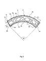
- the voltages Uout1, Uout2 vary as soon as the position encoder unit 30 covers one of the measuring fields M1, M2 of the receiving coils 40a, 40b, as in FIG FIG. 5 shown schematically.
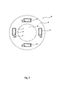
- FIG. 3 an embodiment of the position encoder unit 30 is shown.
- the position encoder unit 30 is provided with, for example, a rotating element (cf. FIGS. 4 and 5 ) and changes their relative position to the receiving coils 40a, 40b by the movement of the rotating element.
- the position encoder unit 30 has a carrier body 31, which may be designed, for example, as a printed circuit board.
- the carrier body 31 is annular. In the middle of the support body 31 has a recess 32 through which the rotating element is feasible.
- the resonant circuits are electromagnetic resonant circuits LC with a capacitor C and a current conductor L as an inductive element.
- the resonant circuit LC can be produced by printed on a printed circuit board tracks. It is preferably a passive resonant circuit LC, which has its own natural frequency. The natural frequencies of the resonant circuits may differ from each other.
- the natural frequency of the resonant circuit LC is the frequency of the exciter field or the AC voltage f.
- the oscillating circuits LC are arranged uniformly spaced around the center of the carrier body. In FIG.
- the resonant circuits do not necessarily have to be arranged within a circle segment or quadrangular. It is also conceivable to provide resonant circuits extending along the circumference of the carrier body, similar to the exciter coil. Furthermore, it is also conceivable to provide a resonant circuit extending around the full circle circumference, wherein the resonant circuits are arranged in different radii.
- the starting and end points of the resonant circuits may have, wherein the starting and end points of the resonant circuits are offset from each other, for example, along the circular path angularly offset.
- each oscillating circuit such that the natural frequency of the oscillating circuits LC differ from each other.
- each resonant circuit can be uniquely identified by means of the natural frequencies, so that it is possible to clearly determine the position of a resonant circuit relative to the measuring fields.
- the frequency of the alternating voltage U ⁇ alternately, for example. Set sequentially in the order of the natural frequencies of the oscillating circuits LC.
- the natural frequency can be set as a function of the differently adjustable AC voltage f.
- the evaluation unit 4 is connected to the receiving coils 40a, 40b and evaluates the output voltages Uout1, Uout2 of the receiving coils 40a, 40b.
- the output voltages Uout1, Uout2 of the receiving coils 40a, 40b are processed by means of demodulators 10.
- the output voltage is usually a sinusoidal or cosinusoidal voltage waveform.
- the amplitude and frequency of the output voltages are excluded by the at least relative angular position of the position encoder unit 30 or of the rotating element.
- FIG. 4 schematically shows the structure of a rotation angle sensor 102.
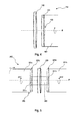
- FIG. 5 the structure of a torque sensor 202 is shown schematically.
- These structures may, for example, with a circuit arrangement 1, as in FIG. 1 shown used. Details of the excitation coil, the receiving coils and the position encoder unit are in the FIGS. 4 and 5 not shown.
- the aforementioned embodiments can be used with these structures.
- the rotation angle sensor 102 off FIG. 4 shows a carrier body 129, on which an excitation coil and two receiving coils are arranged, for example as in FIG. 2 shown.
- the carrier body 129 is attached to a bracket rotatably.
- Adjacent to the carrier body of the excitation coil and the receiving coils is the carrier body 131 of the position encoder unit 130.
- the position encoder unit is mounted on a shaft 180 and rotates with the shaft about the central axis M. This is indicated by the rotating arrow about the central axis M.
- On the outside of the carrier body 131 of the position encoder unit 130 are a plurality of resonant circuits, as in the embodiment of FIG.
- the carrier body 131 of the position encoder unit 130 sits on the end face of the shaft 180.
- the torque sensor 2 has a torsion element 280.
- the torsion element 280 has a first portion 281 a and a second portion 281 b, which are interconnected via a center piece 282.
- the middle piece acts as a kind of torsion spring, so that in the case of an externally applied torque T at one of the sections 281a, 281b, the two sections are rotated relative to each other in torsion angles phi1, phi2 of different magnitudes. Due to the different angles of rotation or torsion angles phi1, phi2 of the first and the second section and the torsional rigidity of the center piece 282, a conclusion on the external torque T can be closed.
- the middle piece 282 passes through a carrier body 229 carrying the excitation coil and the receiving coils (represented by the dashed lines), so that this carrier body 229 is non-rotatably arranged relative to the two portions 281a, 281b of the torsion element 280.
- the position encoder units 230a, 230b each have a carrier body 231a, 231b with recesses through which the center piece 282 is passed to be connected to the respective sections 281a, 281b.
- an encoder unit 230a, 230b which cooperate with the exciter coil and the receiver coils, is arranged on the end faces of the sections 281a, 281b. It may, for example, an encoder unit FIG. 3 be used.
- the coils are arranged on a carrier body 229, which can be arranged between the position transmitter units 230a, 230b. There are two variants of the design possible at this point.
- each position encoder unit 230a, 230b would be associated with an exciter coil and a receiver coil which would be arranged on the opposite side of the carrier body.
- the advantage would be that the position of the position encoder units 230a, 230b could be detected at any time.
- the magnetic influence of the exciter coils on each other and on the receiver coils could lead to a falsification of the measurement results, in particular if the carrier body 229 has a small thickness. This could be prevented by means of a magnetically insulating layer between the respective coil units.
- the disadvantage lies in the fact that the production costs for such a carrier body would be higher.
- the invention is not limited to the aforementioned embodiments.
- the carrier body may be formed, for example, in different shapes. Particularly advantageous are printed circuit boards or films, to which a conductor track can be attached.
- the embodiments can be realized in a simple embodiment with an alternating voltage in one frequency.
- the rotation angle sensor It is also possible to use the rotation angle sensor with a simple circuit arrangement operated at a single AC frequency.
- the evaluation unit 4 is not limited to the above-mentioned embodiment, but can be supplemented by further evaluation electronics.
Abstract
Drehwinkelsensor (2, 102) zum Erfassen der Position eines bewegenden Elements (180), insbesondere Rotors eines elektrischen Motors, aufweisend: - eine Erregerspule (20), welche mit einer Wechselspannung (Uˆ¼) versorgt wird, um ein zur Wechselspannung korrespondierendes Erregerfeld zu erzeugen, - mindestens eine, vorzugsweise zwei, Empfangsspule (40a, 40b), die mit der Erregerspule (20) derart gekoppelt sind, so dass das Erregerfeld in den Emp-fangsspulen (40a, 40b) jeweils eine Spannung (Uout1, Uout2) induziert, und - eine Positionsgebereinheit (30, 130), das mit dem bewegenden Element (180) verbunden ist und mittels dessen die Spannung (Uout1, Uout2) der Empfangsspule beeinflussbar ist, dadurch gekennzeichnet, dass die Positionsgebereinheit (30, 130)mehrere Schwingkreise (LC) mit unterschiedlichen Eigenfrequenzen aufweist.Angle of rotation sensor (2, 102) for detecting the position of a moving element (180), in particular rotor of an electric motor, comprising: - An excitation coil (20), which is supplied with an AC voltage (U¼) to generate a voltage corresponding to the AC voltage exciter field, - At least one, preferably two, receiving coil (40a, 40b) which are coupled to the excitation coil (20) such that the exciter field in the receiving coils (40a, 40b) each induces a voltage (Uout1, Uout2), and - An encoder unit (30, 130) which is connected to the moving element (180) and by means of which the voltage (Uout1, Uout2) of the receiving coil can be influenced, characterized in that the position encoder unit (30, 130) has a plurality of resonant circuits (LC) with different natural frequencies.
Description
Die Erfindung betrifft einen Drehwinkelsensor zum Erfassen des Drehwinkels oder eine Drehmoments eines rotierenden Elements gemäß dem Oberbegriff der unabhängigen Ansprüche.The invention relates to a rotation angle sensor for detecting the rotation angle or a torque of a rotating element according to the preamble of the independent claims.
Aus der
Davon ausgehend liegt der Erfindung die Aufgabe zu Grunde, das bekannte Prinzip für einen Drehwinkelsensor oder einen Drehmomentsensor weiterzubilden.Based on this, the object of the invention is to develop the known principle for a rotation angle sensor or a torque sensor.
Die Aufgabe wird durch die Merkmale der unabhängigen Ansprüche gelöst. Bevorzugte Ausführungsformen sind Gegenstand der abhängigen Ansprüche.The object is solved by the features of the independent claims. Preferred embodiments are subject of the dependent claims.
Der Erfindung liegt der Grundgedanke zu Grunde die Positionsgebereinheit mit mehreren Schwingkreisen zu bestücken, die mittels der Empfangsspule anhand ihrer Eigenfrequenz identifiziert werden können. Die relative Position der Schwingkreise zueinander ändert sich nicht, so dass es möglich ist, anhand einer Messung der Position eines Schwingkreises auf die Position der anderen Schwingkreise zu schließen. Das Prinzip lässt sich dabei sowohl für einen Drehwinkel- als auch für einen Drehmomentsensor nutzen. Vorteilhaft ist es zwei oder mehr Empfangsspulen zu verwenden. In der nachfolgenden Beschreibung wird daher auf mehrere Empfangsspulen Bezug genommen. Nachfolgende Ausführungsformen können im Prinzip auch mit einer Empfangsspule ausgeführt werden.The invention is based on the basic idea of equipping the position encoder unit with a plurality of resonant circuits, which can be identified by means of the receiver coil on the basis of its natural frequency. The relative position of the oscillating circuits relative to one another does not change, so that it is possible to deduce the position of the other oscillating circuits based on a measurement of the position of one oscillating circuit. The principle can be used for both a rotational angle and a torque sensor. It is advantageous to use two or more receiver coils. In the following description, reference will therefore be made to a plurality of receiving coils. Subsequent embodiments can in principle also be carried out with a receiver coil.
Die Positionsgebereinheit ist mit dem zu vermessenden Element, beispielsweise eine rotierende Welle oder ein Torsionselement, verbunden und gibt die Bewegung bzw. Verformung dieses Elements wieder. Durch das Erfassen der absoluten Position oder der relativen Bewegung des bewegenden Elements zu den Empfangsspulen kann der die entsprechende Messgröße über die Positionsgebereinheit entweder relativ zu den Empfangsspulen oder absolut in Bezug auf einen Bezugspunkt erfasst werden. Die Positionsgebereinheit ist ein von der Erregerspule und den Empfangsspulen separates Teil, das bspw. parallel benachbart zu den Spulen angeordnet ist.The position encoder unit is connected to the element to be measured, for example a rotating shaft or a torsion element, and reflects the movement or deformation of this element. By detecting the absolute position or the relative movement of the moving element to the receiving coils of the corresponding measured variable can be detected via the position encoder unit either relative to the receiving coil or absolute with respect to a reference point. The position encoder unit is a separate from the excitation coil and the receiving coil part, which is, for example, arranged in parallel adjacent to the coils.
Eine vorteilhafte Ausführungsform des Drehwinkelsensors weist ein Positionsgebereinheit mit einem Trägerkörper auf, wo die Schwingkreise gleichmäßig um einen Rotationspunkt herum angeordnet sind. Der Messbereich von 360° kann auf diese Weise in mehreren Sektoren bzw. Segmente unterteilt werden, so dass beim erfassen eines Schwingkreises ein Rückschluss auf den jeweiligen Kreissektor bzw. Kreissegment geschlossen werden kann.An advantageous embodiment of the rotation angle sensor has an encoder unit with a carrier body, where the resonant circuits are arranged uniformly around a point of rotation. The measuring range of 360 ° can be divided in this way into several sectors or segments, so that when detecting a resonant circuit, a conclusion can be drawn on the respective circular sector or circular segment.
Die nachfolgenden Ausführungsformen sind sowohl auf den Drehwinkel- als auch auf den Drehmomentsensor anwendbar.The following embodiments are applicable to both the rotation angle and the torque sensor.
Eine vorteilhafte Ausführungsform des erfindungsgemäßen Sensors ist derart ausgebildet, dass der Schwingkreis mindestens ein kapazitives und ein induktives Element aufweist.An advantageous embodiment of the sensor according to the invention is designed such that the resonant circuit has at least one capacitive and one inductive element.
Eine vorteilhafte Ausführungsform des erfindungsgemäßen Sensors ist derart ausgebildet, dass das kapazitive Element ein Kondensator und / oder das induktive Element ein Stromleiter ist. Der Kondensator und das induktive Element können als auf eine Leiterplatine aufgedruckte Leiter oder Leiterbahnen ausgeführt sein. Dies ermöglicht, insbesondere im Zusammenhang mit einem ringförmigen Trägerkörper der Positionsgebereinheit, eine besonders variable Ausnutzung der Anbringfläche auf dem Trägerkörper. Zudem kann die Form der Schwingkreise variabel an den jeweiligen Bedarf angepasst werden.An advantageous embodiment of the sensor according to the invention is designed such that the capacitive element is a capacitor and / or the inductive element is a current conductor. The capacitor and the inductive element may be embodied as printed on a printed circuit conductor or conductor tracks. This allows, in particular in connection with an annular carrier body of the position encoder unit, a particularly variable utilization of the mounting surface on the carrier body. In addition, the shape of the oscillating circuits can be variably adapted to the respective requirements.
Eine vorteilhafte Ausführungsform des erfindungsgemäßen Sensors ist derart ausgebildet, dass die Schwingkreise jeweils einen Anfangs- und Endpunkt aufweisen, wobei die Anfangs- und Endpunkte der Schwingkreise, vorzugsweise entlang einer Bewegungsbahn, versetzt voneinander angeordnet sind. Auf diese Weise ist eine besonders eindeutige Unterscheidung der jeweiligen Schwingkreise voneinander möglich.An advantageous embodiment of the sensor according to the invention is designed such that the resonant circuits each have a start and end point, wherein the starting and end points of the resonant circuits, preferably along a movement path, are arranged offset from each other. In this way, a particularly clear distinction between the respective resonant circuits is possible.
Eine vorteilhafte Ausführungsform des erfindungsgemäßen Sensors ist derart ausgebildet, dass die Eigenfrequenz des Schwingkreises mittels der Verlaufsform des Stromleiters festgelegt wird. Die Verlaufsformen können beispielsweise eine periodische Funktion abbilden. Es ist beispielsweise denkbar, dass der Stromleitern eine sinus-, kosinus-, trapez-, dreiecks-, oder rechteckförmigen Verlauf aufweist.An advantageous embodiment of the sensor according to the invention is designed such that the natural frequency of the resonant circuit is determined by means of the shape of the current conductor. The history forms can, for example, map a periodic function. For example, it is conceivable that the current conductors have a sinusoidal, cosine, trapezoidal, triangular, or rectangular profile.
Eine vorteilhafte Ausführungsform des erfindungsgemäßen Sensors ist derart ausgebildet, dass die Eigenfrequenz des Schwingkreises in Abhängigkeit der Erregerfrequenz festgelegt wird. Diese Ausführungsform ist besonders dann vorteilhaft, wenn die Frequenz der Wechselspannung nicht beliebig festgelegt werden kann.An advantageous embodiment of the sensor according to the invention is designed such that the natural frequency of the resonant circuit is determined as a function of the exciter frequency. This embodiment is particularly advantageous when the frequency of the AC voltage can not be set arbitrarily.
Eine vorteilhafte Ausführungsform des erfindungsgemäßen Sensors ist derart ausgebildet, dass die Wechselspannung eine Spannungsfrequenz aufweist, die in unterschiedliche Frequenzen einstellbar ist. Auf diese Weise ist es möglich, die Frequenz der Wechselspannung und somit auch die Frequenz des Erregerfeldes entsprechend der Eigenfrequenzen der Schwingkreise festzulegen.An advantageous embodiment of the sensor according to the invention is designed such that the AC voltage has a voltage frequency which is adjustable in different frequencies. In this way it is possible to set the frequency of the AC voltage and thus also the frequency of the exciter field according to the natural frequencies of the resonant circuits.
Eine vorteilhafte Ausführungsform des erfindungsgemäßen Sensors ist derart ausgebildet, dass die Spannungsfrequenz mittels Addition mehrerer Spannungsfrequenzen eingestellt wird.An advantageous embodiment of the sensor according to the invention is designed such that the voltage frequency is adjusted by adding a plurality of voltage frequencies.
Eine vorteilhafte Ausführungsform des erfindungsgemäßen Sensors ist derart ausgebildet, dass die Spannungsfrequenz abwechselnd in unterschiedliche Frequenzen einstellbar ist. Mittels dieser Ausführungsform ist es möglich, bestimmte Schwingkreise abwechselnd hintereinander zu erfassen.An advantageous embodiment of the sensor according to the invention is designed such that the voltage frequency is alternately adjustable in different frequencies. By means of this embodiment, it is possible to detect certain oscillating circuits alternately one behind the other.
Eine vorteilhafte Ausführungsform des erfindungsgemäßen Sensors ist derart ausgebildet, dass die Spannungsfrequenz in Abhängigkeit der Eigenfrequenz der Schwingkreise eingestellt wird oder die Eigenfrequenz in Abhängigkeit der unterschiedlich einstellbaren Spannungsfrequenzen festgelegt wird.An advantageous embodiment of the sensor according to the invention is designed such that the voltage frequency is set as a function of the natural frequency of the resonant circuits or the natural frequency is set in dependence of the differently adjustable voltage frequencies.
Die Erfindung wird nachfolgend anhand von Ausführungsbeispielen und Figuren näher beschrieben und es zeigen:
- Die Erfindung umfasst ferner einen Kombination aus einem Drehwinkel- und einem Drehmomentsensor nach einem der vorstehenden Ausführungsformen.
- Fig. 1
- eine schematische Schaltungsanordnung mit einem ersten Ausführungsbeispiel des erfindungsgemäßen Drehwinkelsensors,
- Fig. 2
- eine schematische Darstellung der Erregerspule und der Empfangsspulen,
- Fig. 3
- eine schematische Darstellung der Positionsgebereinheit,
- Fig. 4
- einen schematischen Aufbau eines Drehwinkelsensors, und
- Fig. 5
- einen schematischen Aufbau eines Drehmomentensensors.
- The invention further comprises a combination of a rotational angle and a torque sensor according to one of the preceding embodiments.
- Fig. 1
- a schematic circuit arrangement with a first embodiment of the rotation angle sensor according to the invention,
- Fig. 2
- a schematic representation of the exciter coil and the receiving coil,
- Fig. 3
- a schematic representation of the position encoder unit,
- Fig. 4
- a schematic structure of a rotation angle sensor, and
- Fig. 5
- a schematic structure of a torque sensor.
Die Spannungsquelle 3 ist mit der Erregerspule 20 elektrisch verbunden und versorgt diese mit einer Wechselspannung U~ zum erzeugen eines zur Wechselspannung U~ korrespondierenden Erregerfeldes. Die Wechselspannung U~ weist eine Spannungsfrequenz auf f, die variabel einstellbar ist und in unterschiedliche Spannungsfrequenzen bzw. Frequenzen einstellbar ist. Die Wechselspannung kann beispielsweise abwechselnd in unterschiedliche Frequenzen eingestellt werden. Dies kann derart erfolgen, dass die Spannungsfrequenz f mittels Addition mehrerer Spannungsfrequenzen f1, f2 eingestellt wird. Hierzu weist die Spannungsquelle 3 zunächst zwei Wechselspannungserzeuger 5a und 5b auf, die jeweils eine Wechselspannung in unterschiedlichen Frequenzen f1, f2 erzeugen. Diese Ausgestaltung hat den Vorteil, dass die Wechselspannung U~ leicht durch Variierung der Summenteile veränderbar ist. Die Ausgangssignale der Spannungserzeuger 5a und 5b werden einem Addierer 6 zugeführt. Die Summe der Ausgangssignale werden einer Treibereinheit 7 zugeführt, der aus diesem Signal die Wechselspannung U~ erzeugt und diese der Erregerspule 20 zuführt. Es ist jedoch auch denkbar andere bereits bekannte Lösungen zur Erzeugung einer Wechselspannung in unterschiedlichen Frequenzen zu verwenden.The voltage source 3 is electrically connected to the
Der Sensor 2 umfasst im Wesentlichen die Erregerspule 20, eine Positionsgebereinheit 30 und zwei Empfangsspulen 40a, 40b. In
Die Erregerspule 20 ist vorzugsweise als eine auf einer Leiterplatine aufgedruckte Leiterbahn ausgebildet und um die Empfangsspulen 40a, 40b herum angeordnet, so dass das durch die Wechselspannung erzeugte Erregerfeld eine Spannung in den Empfangsspulen 40a, 40b induziert. Die Erregerspule 20 weist eine Wicklung 21 auf, die einen sich über einen Kreissegment erstreckt. In diesem Ausführungsbeispiel umfasst das Kreissegment im Wesentlichen einen Winkel von alpha=90°. Leichte Abweichungen sind möglich. Denkbar ist auch eine Ausführung der Erreger- und Empfangsspulen über einen vollen Kreisumfang. Die Wicklung 21 ist über zwei Bahnen gewickelt, wobei die Anschlusspunkte 22 außen angeordnet sind. Die Erregerspule 20 ist über die Anschlusspunkte 22 mit der Spannungsquelle 3 verbunden. In radialer Errichtung weist die Erregerspule 20 jeweils eine geradlinige Begrenzung 25a, 25b auf, die mit zwei kreisbogenförmigen Abschnitten 26a, 26b einen Bereich eingrenzen, in der die Empfangsspulen 40a, 40b angeordnet sind. Auf diese Weise wird sichergestellt, dass die Empfangsspulen 40a, 40b mit der Erregerspule 20 induktiv gekoppelt sind.The
Die Empfangsspule 40a, 40b weisen jeweils eine Wicklung 43a, 43b auf. Die Wicklungen 43a, 43b haben einen sinus- bzw. kosinusförmigen Verlauf. Denkbar sind auch andere periodische Formen, wie in den anderen Ausführungsbeispielen gezeigt. Die Wicklungen 43a, 43b haben einen Anfangspunkt 41a, 41b, die an einem Ende des Kreissegments angeordnet sind. Die Wicklungen 43a, 43b laufen von dort entsprechend ihrer periodischer Form entlang des Kreissegments bis zum anderen Ende des Kreissegments. Von dem anderen Ende laufen die Wicklungen 43a, 43b wie eine reflektierte Welle zum ersten Ende des Kreissegments zurück. Vorzugsweise ist die Periodenlänge der Wicklungen derart ausgeführt, dass ein ganzzahliges Vielfaches der Periode innerhalb des Kreissegments hineinpasst, wie im Falle der Empfangsspule 40a. Andernfalls wird das, wie im Falle der Empfangsspule 40b, die Wicklung 43b über einen im Wesentlichen Abschnitt im Wesentlichen entlang der Wicklung der Erregerspule 20 nach innen geführt. Von dort aus verläuft die Wicklung 43b nach der vorgegebenen periodischen Form. Das Ende der Wicklung 43a, 43b bildet jeweils ein Endpunkt 42a, 42b. Über die Anfangs- und Endpunkte 41a, 42a, 41b, 42b wird die Ausgasspannung Uout1~, Uout2~ von den Empfangsspulen abgegriffen.The receiving
Die Empfangsspulen 40a, 40b weisen mehrere Messfelder auf, in
Die Erregerspule 20 und die Empfangsspulen 40a, 40b sind vorzugsweise auf einer Leiterplatine mittels aufgedruckten Leiterbahnen ausgebildet. Der Trägerkörper, in dem Fall die Leiterplatine, ist kreissegmentförmig ausgebildet. Vorteilhafterweise nicht wesentlich größer, das der Bereich, den die Erregerspule 20 einnimmt.The
Aufgrund der induktiven Kopplung mit der Erregerspule 20 erzeugen die zwei Empfangsspulen 40a, 40b (es können auch mehr sein) jeweils eine Ausgangsspannung Uout1, Uout2 (vgl.
In
Die Positionsgebereinheit 30 weist einen Trägerkörper 31 auf, der beispielsweise als eine Leiterplatine ausgeführt sein kann. Der Trägerkörper 31 ist ringförmig ausgebildet. In der Mitte weist der Trägerkörper 31 eine Ausnehmung 32 auf, durch die das rotierende Element durchführbar ist.The
Auf einer Fläche des Trägerkörpers 31 sind mehrere Schwingkreise LC innerhalb des ringförmigen Bereichs angeordnet. Bei den Schwingkreisen handelt es sich um elektromagnetische Schwingkreise LC mit einem Kondensator C und einem Stromleiter L als induktives Element. Der Schwingkreis LC kann mittels auf einer Leiterplatine aufgedruckten Leiterbahnen hergestellt werden. Es handelt sich vorzugsweise um einen passiven Schwingkreis LC, der eine eigene Eigenfrequenz aufweist. Die Eigenfrequenzen der Schwingkreise können sich voneinander unterscheiden. Vorzugsweise beträgt die Eigenfrequenz des Schwingkreis LC der Frequenz des Erregerfeldes bzw. der Wechselspannungsfrequenz f. Vorzugsweise sind die Schwingkreise LC um den Mittelpunkt des Trägerkörper herum gleichmäßig beabstandet angeordnet. In ![]()
ist, wobei alpha der Winkel ist, über den sich das Kreissegment der Erregerspule bzw. Empfangsspulen erstreckt.On one surface of the ![]()
where alpha is the angle through which the circular segment of the excitation coil (s) extends.
Die Schwingkreise müssen nicht zwangsläufig innerhalb eines Kreissegments angeordnet oder viereckig ausgebildet sein. Es ist auch denkbar sich entlang des Umfangs des Trägerkörpers verlaufende Schwingkreise, ähnlich zu der Erregerspule, vorzusehen. Ferner ist es auch denkbar eine um den vollen Kreisumfang verlaufenden Schwingkreis vorzusehen, wobei die Schwingkreise in unterschiedlichen Radien angeordnet sind. Die Anfangs- und Endpunkte der Schwingkreise können dabei aufweisen, wobei die Anfangs- und Endpunkte der Schwingkreise versetzt voneinander angeordnet sein, beispielsweise entlang der Kreisbahn winkelversetzt.The resonant circuits do not necessarily have to be arranged within a circle segment or quadrangular. It is also conceivable to provide resonant circuits extending along the circumference of the carrier body, similar to the exciter coil. Furthermore, it is also conceivable to provide a resonant circuit extending around the full circle circumference, wherein the resonant circuits are arranged in different radii. The starting and end points of the resonant circuits may have, wherein the starting and end points of the resonant circuits are offset from each other, for example, along the circular path angularly offset.
Besonders vorteilhaft ist es, jeden Schwingkreis derart auszulegen, dass sich die Eigenfrequenz der Schwingkreise LC voneinander unterscheiden. Auf diese Weise ist mittels der Eigenfrequenzen jeder Schwingkreis eindeutig identifizierbar, so dass es möglich ist, die Position eines Schwingkreises relativ zu den Messfeldern eindeutig festzustellen. Vorteilhafterweise wird hierzu die Frequenz der Wechselspannung U~ abwechselnd, bspw. nacheinander in der Reihenfolge der Eigenfrequenzen der Schwingkreise LC eingestellt. Alternativ kann die Eigenfrequenz in Abhängigkeit der unterschiedlich einstellbaren Wechselspannungsfrequenzen f festgelegt werden.It is particularly advantageous to design each oscillating circuit such that the natural frequency of the oscillating circuits LC differ from each other. In this way, each resonant circuit can be uniquely identified by means of the natural frequencies, so that it is possible to clearly determine the position of a resonant circuit relative to the measuring fields. Advantageously, for this purpose, the frequency of the alternating voltage U ~ alternately, for example. Set sequentially in the order of the natural frequencies of the oscillating circuits LC. Alternatively, the natural frequency can be set as a function of the differently adjustable AC voltage f.
Die Auswerteeinheit 4 ist mit den Empfangsspulen 40a, 40b verbunden und wertet die Ausgangsspannungen Uout1, Uout2 der Empfangsspulen 40a, 40b aus. Die Ausgangsspannungen Uout1, Uout2 der Empfangsspulen 40a, 40b werden mittels Demodulatoren 10 verarbeitet. Als Ausgangsspannung wird in der Regel ein sinus- oder kosinusförmiger Spannungsverlauf ausgegeben. Die Amplitude und Frequenz der Ausgangsspannungen gibt Ausschluss über die zumindest relative Winkelposition der Positionsgebereinheit 30 bzw. des rotierenden Elements.The evaluation unit 4 is connected to the receiving
Nachfolgend werden die Ausführungsbeispiele aus
Der Drehwinkelsensor 102 aus
Der Drehmomentsensor 2 weist ein Torsionselement 280 auf. Das Torsionselement 280 weist einen ersten Abschnitt 281a und einen zweiten Abschnitt 281b auf, die über ein Mittelstück 282 miteinander verbunden sind. Das Mittelstück wirkt als eine Art Torsionsfeder, so dass bei einem außenanliegenden Drehmoment T an eines der Abschnitte 281a, 281b die zwei Abschnitte in unterschiedlich großen Torsionswinkeln phi1, phi2 zueinander verdreht werden. Aufgrund der unterschiedlichen Verdrehwinkeln bzw. Torsionswinkeln phi1, phi2 des ersten und des zweiten Abschnitts sowie der Torsionssteifigkeit des Mittelstücks 282 kann ein Rückschluss auf das außenanliegende Drehmoment T geschlossen werden.The torque sensor 2 has a
Das Mittelstück 282 geht durch einen die Erregerspule und die Empfangsspulen tragenden Trägerkörper 229 hindurch (dargestellt durch die gestrichelten Linien), so dass dieser Trägerkörper 229 zu den zwei Abschnitten 281a, 281b des Torsionselements 280 drehfest angeordnet ist. Darüber hinaus weisen die Positionsgebereinheiten 230a, 230b jeweils einen Trägerkörper 231a, 231b mit Ausnehmungen auf, durch welche das Mittelstück 282 hindurchgeführt ist, um mit den jeweiligen Abschnitten 281a, 281b verbunden zu sein.The
Hierzu ist an den Stirnseiten der Abschnitte 281a, 281b jeweils eine Positionsgebereinheit 230a, 230b angeordnet, die mit der Erregerspule und den Empfangsspulen zusammenwirken. Es kann beispielsweise eine Positionsgebereinheit aus
Zum einen ist es denkbar auf jede Seiten des Trägerkörpers 229 jeweils eine Erregerspule und mehrere Empfangsspulen anzuordnen. Jeder Positionsgebereinheit 230a, 230b wäre eine Erregerspule und eine Empfangsspule zugeordnet, die auf der gegenüberliegenden Seite des Trägerkörpers angeordnet wären. Der Vorteil wäre, dass die Position der Positionsgebereinheiten 230a, 230b jederzeit erfasst werden könnten. Es wäre jedoch zu bedenken, dass der magnetische Einfluss der Erregerspulen zueinander und zu den Empfangsspulen zu einer Verfälschung der Messergebnisse führen könnte, insbesondere wenn der Trägerkörper 229 eine geringe Dicke aufweist. Dies könnte mittels einer magnetisch isolierenden Schicht zwischen den jeweiligen Spuleneinheiten verhindert werden. Der Nachteil lege darin, dass die Herstellungskosten für einen solchen Trägerkörper höher wären.On the one hand, it is conceivable to arrange an exciter coil and a plurality of receiver coils on each side of the
Alternativ ist es daher auch denkbar, die Position der einzelnen Positionsgebereinheiten 230a, 230b mittels der Ansteuerung der darauf aufgebrachten Schwingkreise zu erfassen. Hierzu würde man die jeweiligen Eigenfrequenzen der Schwingkreise als Wechselspannungsfrequenz einstellen. Die Positionsmessung der jeweiligen Positionsgebereinheit 230a, 230b würde dann gezielt über die Eigenfrequenzen der jeweiligen Schwingkreise zu regeln. Bei entsprechend schneller Umschaltung der Wechselspannungsfrequenz wäre diese Variante eine hinnehmbare Alternative zu einer dauerhaften Messung der Positionsgebereinheiten 231a, 231b. Besonders vorteilhaft wäre es dabei die Wicklungen der Empfangsspulen und / oder der Erregerspulen auf zumindest abschnittsweise auf beiden Seiten des Trägerkörpers 229 anzuordnen.Alternatively, it is therefore also conceivable to detect the position of the individual
Die Erfindung ist nicht auf die vorgenannten Ausführungsbeispiele beschränkt. Der Trägerkörper kann beispielsweise in unterschiedlichen Formen ausgebildet sein. Besonders vorteilhaft sind Leiterplatinen oder Folien, auf die eine Leiterbahn anbringbar ist. Ferner können die Ausführungsbeispiele in einer einfachen Ausführung auch mit einer Wechselspannung in einer Frequenz realisiert werden.The invention is not limited to the aforementioned embodiments. The carrier body may be formed, for example, in different shapes. Particularly advantageous are printed circuit boards or films, to which a conductor track can be attached. Furthermore, the embodiments can be realized in a simple embodiment with an alternating voltage in one frequency.
Es ist ferner möglich, den Drehwinkelsensor mit einer einfachen Schaltungsanordnung zu verwenden, die mit einer einzigen Wechselspannungsfrequenz betrieben wird. Des Weiteren ist die Auswerteeinheit 4 nicht auf das oben genannte Ausführungsbeispiel beschränkt, sondern kann durch weitere Auswerteelektronik ergänzt werden.It is also possible to use the rotation angle sensor with a simple circuit arrangement operated at a single AC frequency. Furthermore, the evaluation unit 4 is not limited to the above-mentioned embodiment, but can be supplemented by further evaluation electronics.
Claims (13)
Applications Claiming Priority (1)
| Application Number | Priority Date | Filing Date | Title |
|---|---|---|---|
| DE102013225921.2A DE102013225921A1 (en) | 2013-12-13 | 2013-12-13 | Inductive rotation angle and torque sensor with a position transducer unit equipped with oscillating circuits |
Publications (1)
| Publication Number | Publication Date |
|---|---|
| EP2884236A1 true EP2884236A1 (en) | 2015-06-17 |
Family
ID=52101144
Family Applications (1)
| Application Number | Title | Priority Date | Filing Date |
|---|---|---|---|
| EP14197720.7A Ceased EP2884236A1 (en) | 2013-12-13 | 2014-12-12 | Inductive rotational angle and torque sensor with a position sender unit comprising resonant circuits |
Country Status (2)
| Country | Link |
|---|---|
| EP (1) | EP2884236A1 (en) |
| DE (1) | DE102013225921A1 (en) |
Cited By (5)
| Publication number | Priority date | Publication date | Assignee | Title |
|---|---|---|---|---|
| CN109383620A (en) * | 2017-08-14 | 2019-02-26 | 丹佛斯动力系统有限公司 | Hydraulic steering |
| CN109952492A (en) * | 2016-09-09 | 2019-06-28 | 罗伯特·博世有限公司 | Rotation angle sensor and stator component for rotation angle sensor |
| CN111819529A (en) * | 2018-05-02 | 2020-10-23 | 普瑞有限公司 | Input device for determining positional information, comprising an operating element and an influence of an electromagnetic alternating field |
| CN113672130A (en) * | 2021-08-24 | 2021-11-19 | 维沃移动通信有限公司 | Shortcut operation method and device, electronic equipment and storage medium |
| EP4151954A1 (en) * | 2021-09-17 | 2023-03-22 | Scania CV AB | Sensor arrangement for determining an angular position of a shaft in a vehicle |
Families Citing this family (5)
| Publication number | Priority date | Publication date | Assignee | Title |
|---|---|---|---|---|
| DE102014212971A1 (en) | 2014-07-03 | 2016-01-07 | Continental Teves Ag & Co. Ohg | Angle encoder unit for an inductive angle sensor with a reference resonant circuit |
| DE102016100260A1 (en) * | 2016-01-08 | 2017-07-13 | Turck Holding Gmbh | Distance sensor with several positionable tracers |
| DE102018213249A1 (en) | 2018-08-07 | 2020-02-13 | Robert Bosch Gmbh | Sensor system for determining at least one rotational property of a rotating element |
| DE102020110666A1 (en) | 2020-04-20 | 2021-10-21 | Schaeffler Technologies AG & Co. KG | Sensor arrangement for detecting a torque and an angular position |
| DE102020212557A1 (en) | 2020-10-05 | 2022-04-07 | Thyssenkrupp Ag | Sensor device for detecting an angle of rotation |
Citations (4)
| Publication number | Priority date | Publication date | Assignee | Title |
|---|---|---|---|---|
| EP1666836A2 (en) * | 2004-11-19 | 2006-06-07 | AB Elektronik GmbH | Torque sensor and rotation detector |
| EP1925914A2 (en) * | 2006-11-22 | 2008-05-28 | AB Elektronik GmbH | Inductive sensor for engaging two switching elements |
| EP1828722B1 (en) | 2004-12-20 | 2011-11-02 | Howard, Mark Anthony | Inductive position sensor |
| GB2493399A (en) * | 2011-08-05 | 2013-02-06 | Tt Electronics Technology Ltd | Inductive position sensor with multiple resonant circuits of differing resonant frequencies |
Family Cites Families (3)
| Publication number | Priority date | Publication date | Assignee | Title |
|---|---|---|---|---|
| GB2394293A (en) * | 2002-10-16 | 2004-04-21 | Gentech Invest Group Ag | Inductive sensing apparatus and method |
| DE202008008477U1 (en) * | 2007-06-27 | 2008-10-09 | Ab Elektronik Gmbh | Rod-shaped linear sensor |
| ES2553890T3 (en) * | 2008-03-26 | 2015-12-14 | Elmos Semiconductor Ag | Inductive position sensor |
-
2013
- 2013-12-13 DE DE102013225921.2A patent/DE102013225921A1/en not_active Withdrawn
-
2014
- 2014-12-12 EP EP14197720.7A patent/EP2884236A1/en not_active Ceased
Patent Citations (4)
| Publication number | Priority date | Publication date | Assignee | Title |
|---|---|---|---|---|
| EP1666836A2 (en) * | 2004-11-19 | 2006-06-07 | AB Elektronik GmbH | Torque sensor and rotation detector |
| EP1828722B1 (en) | 2004-12-20 | 2011-11-02 | Howard, Mark Anthony | Inductive position sensor |
| EP1925914A2 (en) * | 2006-11-22 | 2008-05-28 | AB Elektronik GmbH | Inductive sensor for engaging two switching elements |
| GB2493399A (en) * | 2011-08-05 | 2013-02-06 | Tt Electronics Technology Ltd | Inductive position sensor with multiple resonant circuits of differing resonant frequencies |
Cited By (11)
| Publication number | Priority date | Publication date | Assignee | Title |
|---|---|---|---|---|
| CN109952492A (en) * | 2016-09-09 | 2019-06-28 | 罗伯特·博世有限公司 | Rotation angle sensor and stator component for rotation angle sensor |
| US20190242726A1 (en) * | 2016-09-09 | 2019-08-08 | Robert Bosch Gmbh | Rotary Sensor and Stator Element for Same |
| US10955262B2 (en) | 2016-09-09 | 2021-03-23 | Robert Bosch Gmbh | Rotation angle sensor for a stator |
| CN109952492B (en) * | 2016-09-09 | 2021-07-20 | 罗伯特·博世有限公司 | Rotation angle sensor and stator element for a rotation angle sensor |
| CN109383620A (en) * | 2017-08-14 | 2019-02-26 | 丹佛斯动力系统有限公司 | Hydraulic steering |
| US10862382B2 (en) | 2017-08-14 | 2020-12-08 | Danfoss Power Solutions Aps | Hydraulic steering arrangement |
| CN109383620B (en) * | 2017-08-14 | 2021-04-20 | 丹佛斯动力系统有限公司 | Hydraulic steering device |
| CN111819529A (en) * | 2018-05-02 | 2020-10-23 | 普瑞有限公司 | Input device for determining positional information, comprising an operating element and an influence of an electromagnetic alternating field |
| CN113672130A (en) * | 2021-08-24 | 2021-11-19 | 维沃移动通信有限公司 | Shortcut operation method and device, electronic equipment and storage medium |
| EP4151954A1 (en) * | 2021-09-17 | 2023-03-22 | Scania CV AB | Sensor arrangement for determining an angular position of a shaft in a vehicle |
| WO2023043355A1 (en) * | 2021-09-17 | 2023-03-23 | Scania Cv Ab | Sensor arrangement for determining an angular position of a shaft in a vehicle |
Also Published As
| Publication number | Publication date |
|---|---|
| DE102013225921A1 (en) | 2015-07-02 |
Similar Documents
| Publication | Publication Date | Title |
|---|---|---|
| EP2884236A1 (en) | Inductive rotational angle and torque sensor with a position sender unit comprising resonant circuits | |
| EP3642567B1 (en) | Rotational angle sensor | |
| EP3420316B1 (en) | Rotation angle sensor | |
| DE102006026543B4 (en) | Position encoder and associated method for detecting a position of a rotor of a machine | |
| EP2105713B1 (en) | Positioning device and method for its operation | |
| EP3645977B1 (en) | Sensor system for determining at least one rotation characteristic of a rotating element | |
| EP3029427B1 (en) | Device and algorithm for radial mechanically absolute angle determination for a shaft | |
| EP3555571B1 (en) | Sensor system for determining at least one rotation property of an element rotating about at least one rotational axis | |
| DE102017222063A1 (en) | Inductive position measuring device | |
| DE102013224098A1 (en) | Sensor arrangement for detecting angles of rotation on a rotating component in a vehicle | |
| EP2884238A1 (en) | Inductive rotation angle sensor with a circular segment shaped excitation and receiver coil | |
| DE102019127297A1 (en) | Sensor device for detecting the angular position of a rotatable shaft and steering arrangement of a vehicle | |
| EP2834601B1 (en) | Method and arrangement for determining the position of a component | |
| WO2000046093A1 (en) | Device for detecting the angle position of a motor vehicle steering wheel | |
| EP2884237A1 (en) | Inductive rotation angle sensor | |
| DE102014218982A1 (en) | Sensor arrangement for path and / or angle measurement | |
| WO2017129458A2 (en) | Machine, in particular an electric drive motor and method for wireless data transmission between a rotor and a stator and/or for detecting the speed of the rotor | |
| DE102013215320A1 (en) | Device for detecting the torque in a shaft | |
| EP2884234A1 (en) | Inductive sensor with a measured displacement of any length | |
| DE202006008962U1 (en) | Position generator for detecting the position of the rotor of an engine based on a change in the inductance of an inductive component dependent on movement | |
| DE102004026311A1 (en) | Position indicator has two transmitter coils and one receiver coil with inductive coupling and also one divisional structure whereby transmitter coil windings enclose two overlapping areas which generate different magnetic flow directions | |
| DE102016224854A1 (en) | Sensor system for determining at least one rotational property of an element rotating about at least one axis of rotation | |
| DE102013225873A1 (en) | Inductive sensor based on the vernier principle | |
| DE202015103893U1 (en) | Arrangement of a microgenerator circuit | |
| DE102017222402B4 (en) | Angle of rotation measuring device |
Legal Events
| Date | Code | Title | Description |
|---|---|---|---|
| PUAI | Public reference made under article 153(3) epc to a published international application that has entered the european phase |
Free format text: ORIGINAL CODE: 0009012 |
|
| 17P | Request for examination filed |
Effective date: 20141212 |
|
| AK | Designated contracting states |
Kind code of ref document: A1 Designated state(s): AL AT BE BG CH CY CZ DE DK EE ES FI FR GB GR HR HU IE IS IT LI LT LU LV MC MK MT NL NO PL PT RO RS SE SI SK SM TR |
|
| AX | Request for extension of the european patent |
Extension state: BA ME |
|
| R17P | Request for examination filed (corrected) |
Effective date: 20151217 |
|
| RBV | Designated contracting states (corrected) |
Designated state(s): AL AT BE BG CH CY CZ DE DK EE ES FI FR GB GR HR HU IE IS IT LI LT LU LV MC MK MT NL NO PL PT RO RS SE SI SK SM TR |
|
| 17Q | First examination report despatched |
Effective date: 20180607 |
|
| RAP1 | Party data changed (applicant data changed or rights of an application transferred) |
Owner name: CONTINENTAL TEVES AG & CO. OHG |
|
| STAA | Information on the status of an ep patent application or granted ep patent |
Free format text: STATUS: THE APPLICATION HAS BEEN REFUSED |
|
| 18R | Application refused |
Effective date: 20190118 |