EP3029427B1 - Device and algorithm for radial mechanically absolute angle determination for a shaft - Google Patents
Device and algorithm for radial mechanically absolute angle determination for a shaft Download PDFInfo
- Publication number
- EP3029427B1 EP3029427B1 EP15197409.4A EP15197409A EP3029427B1 EP 3029427 B1 EP3029427 B1 EP 3029427B1 EP 15197409 A EP15197409 A EP 15197409A EP 3029427 B1 EP3029427 B1 EP 3029427B1
- Authority
- EP
- European Patent Office
- Prior art keywords
- magnetic field
- magnetic
- shaft
- signal
- sensor
- Prior art date
- Legal status (The legal status is an assumption and is not a legal conclusion. Google has not performed a legal analysis and makes no representation as to the accuracy of the status listed.)
- Active
Links
- 238000011156 evaluation Methods 0.000 claims description 14
- NCGICGYLBXGBGN-UHFFFAOYSA-N 3-morpholin-4-yl-1-oxa-3-azonia-2-azanidacyclopent-3-en-5-imine;hydrochloride Chemical compound Cl.[N-]1OC(=N)C=[N+]1N1CCOCC1 NCGICGYLBXGBGN-UHFFFAOYSA-N 0.000 claims description 8
- 101100234408 Danio rerio kif7 gene Proteins 0.000 claims description 7
- 101100221620 Drosophila melanogaster cos gene Proteins 0.000 claims description 7
- 101100398237 Xenopus tropicalis kif11 gene Proteins 0.000 claims description 7
- 238000004519 manufacturing process Methods 0.000 claims description 5
- 230000010363 phase shift Effects 0.000 claims description 2
- 238000012937 correction Methods 0.000 description 11
- 230000006870 function Effects 0.000 description 9
- 238000005259 measurement Methods 0.000 description 8
- 238000012545 processing Methods 0.000 description 6
- 230000008859 change Effects 0.000 description 4
- 238000010276 construction Methods 0.000 description 4
- 230000007704 transition Effects 0.000 description 4
- 238000000034 method Methods 0.000 description 3
- 230000008569 process Effects 0.000 description 3
- 230000008901 benefit Effects 0.000 description 2
- 101150118300 cos gene Proteins 0.000 description 2
- 238000009434 installation Methods 0.000 description 2
- 230000033001 locomotion Effects 0.000 description 2
- 230000000737 periodic effect Effects 0.000 description 2
- 238000004364 calculation method Methods 0.000 description 1
- 238000013461 design Methods 0.000 description 1
- 238000011161 development Methods 0.000 description 1
- 238000005516 engineering process Methods 0.000 description 1
- 230000002349 favourable effect Effects 0.000 description 1
- 230000000704 physical effect Effects 0.000 description 1
- 238000007781 pre-processing Methods 0.000 description 1
- 230000009467 reduction Effects 0.000 description 1
- 238000005070 sampling Methods 0.000 description 1
- 230000001953 sensory effect Effects 0.000 description 1
- 238000012360 testing method Methods 0.000 description 1
- 238000012546 transfer Methods 0.000 description 1
Images


Classifications
-
- H—ELECTRICITY
- H02—GENERATION; CONVERSION OR DISTRIBUTION OF ELECTRIC POWER
- H02K—DYNAMO-ELECTRIC MACHINES
- H02K11/00—Structural association of dynamo-electric machines with electric components or with devices for shielding, monitoring or protection
- H02K11/20—Structural association of dynamo-electric machines with electric components or with devices for shielding, monitoring or protection for measuring, monitoring, testing, protecting or switching
- H02K11/21—Devices for sensing speed or position, or actuated thereby
- H02K11/215—Magnetic effect devices, e.g. Hall-effect or magneto-resistive elements
-
- G—PHYSICS
- G01—MEASURING; TESTING
- G01D—MEASURING NOT SPECIALLY ADAPTED FOR A SPECIFIC VARIABLE; ARRANGEMENTS FOR MEASURING TWO OR MORE VARIABLES NOT COVERED IN A SINGLE OTHER SUBCLASS; TARIFF METERING APPARATUS; MEASURING OR TESTING NOT OTHERWISE PROVIDED FOR
- G01D5/00—Mechanical means for transferring the output of a sensing member; Means for converting the output of a sensing member to another variable where the form or nature of the sensing member does not constrain the means for converting; Transducers not specially adapted for a specific variable
- G01D5/12—Mechanical means for transferring the output of a sensing member; Means for converting the output of a sensing member to another variable where the form or nature of the sensing member does not constrain the means for converting; Transducers not specially adapted for a specific variable using electric or magnetic means
- G01D5/244—Mechanical means for transferring the output of a sensing member; Means for converting the output of a sensing member to another variable where the form or nature of the sensing member does not constrain the means for converting; Transducers not specially adapted for a specific variable using electric or magnetic means influencing characteristics of pulses or pulse trains; generating pulses or pulse trains
- G01D5/24471—Error correction
- G01D5/2449—Error correction using hard-stored calibration data
Definitions
- the present invention relates to a vehicle, a rotary machine and a device for the mechanical absolute angle determination of a shaft of a rotary machine.
- the present invention relates to a low-cost sensor concept for rotor position determination, which also allows a simple flexible construction.
- rotor position information is required for the control and regulation of EC motors in automotive electronics as well as in electrically propelled means of locomotion (for example pedelecs and e-bikes). This is determined by an angular position in which the motor shaft is located. Depending on the requirements of the product, the angle must be measured with a high degree of accuracy (less than 0.5 °).
- electrically absolute angle measurement only the angle change within a pole pair change of the motor is considered.
- mechanical absolute angle measurement an angle change over 360 ° of the motor shaft is detected (regardless of the number of motor poles).
- the sensor system consists of a sensor magnet (magnetic field sensor) and a magnetoresistive sensor (such as AMR, GMR or TMR). These systems are designed axially, ie, the sensor magnet is at the motor shaft end fixed axially. The sensor is usually positioned parallel to the sensor magnet. Such a construction will be described in connection with FIG. 1 received.
- Such a mechanical arrangement raises the requirement for the electronics to be placed above the motor shaft. This fact forces products in which the main electronics for the motor control is not outside the motor shaft to more effort and more cost to place the sensor above the shaft end. Therefore, radial placement of the sensors to the motor shaft would be of great importance as an alternative.
- DE 10 2010 040 861 A1 discloses an electronically commutated electric motor with a rotor position sensor, which shows a radial sensing, which starts from an integer ratio between the donor magnet and the rotor magnet pole pair number.
- the arrangement shown can therefore make only an electrically absolute angle determination.
- DE 10 2011 079 962 A1 discloses an electric motor with a rotor position sensor in which the stray field of the rotor is detected and used for angular position determination. Again, only an electrically absolute angular position is determined.
- EP 2 559 971 A1 discloses an absolute rotation detector with two magnetic field sensors offset by 90 °, the absolute angle determination taking advantage of the known pole width variation.
- such products should be equipped with a motor control electronics parallel to the motor shaft.
- a cost-effective, mechanically absolute angle measurement with a measurement inaccuracy of less than 1% is to be made possible.
- the above-identified object is achieved by a device for mechanically absolute angle determination of a shaft of a rotary machine according to claim 1.
- the device comprises a magnetic ring with a plurality of magnetic poles.
- the magnetic ring is used exclusively for angle determination and can preferably (exclusively) comprise permanent magnets.
- a first magnetic field sensor and a second magnetic field sensor and an evaluation unit are provided.
- the Magnetic ring is set up, in particular in the azimuthal extension direction on / on the shaft of the rotary machine (for example an electric motor, an electric generator or the like) to be arranged.
- the magnetic field sensors are arranged to detect the magnetic fields provided by the magnetic rim as they move past the magnetic field sensors as the shaft rotates.
- the evaluation unit is set up to compare signals based on magnetic field signals of the magnetic field sensors.
- the electrical signals provided by the magnetic field sensors provide information on the basis of which the evaluation unit carries out a comparison.
- a preprocessing of the electrical signals of the magnetic field sensors is therefore expressly considered to be possible within the scope of the present invention.
- An unambiguous assignment of properties of the analyzed signals to a mechanically absolute angular position is effected according to the invention by identifying production-related irregularities of the magnetic ring or its magnetic poles (eg scattered in the azimuthal direction (rotational direction) or the like), in order to obtain a mechanically absolute basis by means of identified irregularities Determine the angle of the shaft.
- the use of two sensors on one and the same magnetic rim makes such a differentiated examination of the magnetic fields possible that, as it were, a "magnetic fingerprint" of the magnetic rim example can be created and compared with a predefined reference. Based on the reference, the signals generated by the magnetic field sensors can thus be used to determine a mechanically absolute angular position of the shaft. In the prior art usual expenses for the mechanical absolute angle determination can therefore be omitted according to the invention.
- the radial arrangement of the sensors allows a simple construction of the device according to the invention and thus a cost-effective and space-optimized design of appropriately equipped rotary machines.
- the evaluation unit of the device is further configured to compare the signals of the magnetic field sensors with each other by forming a difference between a signal of the first magnetic field sensor and a signal of the second magnetic field sensor.
- Both the signal of The first magnetic field sensor as well as the signal of the second magnetic field sensor can each be based on a multiplicity of individual signals and generated by their combination.
- a plurality of sensor heads or sensor units may be provided in the magnetic field sensors used. Due to the difference identical components are suppressed in the sensor signals and production-related irregularities of the magnetic ring occur particularly favorable in appearance.
- the first magnetic field sensor will emit two signals, wherein a phase shift between the first magnetic field signal and the second magnetic field signal may exist.
- the magnetic field signals essentially have the properties of a sine function or a cosine function
- arctangent functions can be created / calculated from both magnetic field signals in a particularly simple manner, which represent a substantially section-wise linear representation of the angle of the rotary machine or its shaft.
- a third or a fourth magnetic field signal which are generated by the second magnetic field sensor.
- the arctangent functions of the first magnetic field sensor or of the second magnetic field sensor produced as described above are subtracted from one another in order to generate an angle signal from the sensor signal.
- This angle is clearly over a magnetic pole pair of the ring magnet (electrically absolute angle).
- a clear angle signal over 360 ° mechanical rotation of the magnet, the difference between the two angle signals from the sensor 1 and sensor 2 is formed.
- the difference signal is not periodic over the respective pole pairs and can therefore be used to generate a unique characteristic for the respective magnetic pole pair.
- the magnetic ring is adapted to enclose the shaft of the rotary machine in the radial direction.
- the magnetic ring extends in the azimuthal direction to the shaft and in particular is not arranged on one end face (an extreme point in the axial direction). In this way, rotary machines equipped with a device according to the invention can obtain a cost-effective and space-optimized construction.
- the magnetic ring may have at least eight magnetic poles. Since in this case an ideal magnetic pole shape (100% homogeneity of the magnetic poles) does not provide identical magnetic pole transitions in each case, a device according to the invention can utilize production-related irregularities in order to distinguish the substantially identical magnetic pole transitions from each other. Accordingly, a cost angle determination can be realized at the same time high angular resolution.
- the first magnetic field sensor and the second magnetic field sensor are preferably arranged at predefined and known angular positions in the direction of rotation relative to one another. In other words, it is known how many degrees in the direction of rotation the position of the first magnetic field sensor deviates from the position of the second magnetic field sensor. In this way, a rapid and cost-effective transfer of the signals of the first magnetic field sensor in the coordinate system of the second magnetic field sensor (or vice versa) take place. Accordingly, even fine irregularities, which are found in the difference signal between the signal of the first magnetic field sensor and the signal of the second magnetic field sensor, can be resolved for angle determination.
- the two magnetic field sensors can of course also be arranged at one and the same angular position.
- the signals can also be shifted to each other in circuit technology and / or by means of digital signal processing in order to generate a suitable difference signal.
- peaks in the difference may be used as signal range boundaries for comparison of the signal with stored references.
- the first magnetic field sensor and / or the second magnetic field sensor can be configured as Hall and / or XMR sensors.
- the use of one or more of the aforementioned sensor principles can be done inexpensively by standard elements and has also been proven in tests.
- the evaluation unit can be set up to read out a reference (for example from a data memory), by means of which the identified irregularities can be classified.
- a reference for example from a data memory
- the "magnetic fingerprint" of the magnetic ring is determined and compared with references to which a respective rotational angular position of the shaft is assigned.
- a comparison with the references can be made and the one angular position assumed to be the present case, which determined the lowest Distance (eg mathematical deviation).
- a rotary machine which has a shaft, a housing and a device according to the invention.
- the shaft is at least partially disposed within a housing wall of the housing.
- the shaft extends through the housing wall completely, while the magnetic ring of the device is disposed within the housing.
- the device according to the invention is located in the region of that housing volume in which the magnetically relevant components (for example rotor and stator) of the rotary machine are also arranged.
- a magnetic rim extended in the azimuthal direction ie in the circumferential direction
- This is particularly cost-effective, allows a flexible shape of the rotary machine and according to the invention nevertheless an angle determination with a maximum tolerance of less than 1 °, in particular less than 0.5 °.
- a vehicle which is designed, for example, as an electrically drivable bicycle (pedelec, e-bike or the like).
- a device according to the invention or a rotary machine according to the invention is proposed.
- FIG. 1 shows a rotary machine 10 with an electric drive unit 3, which outputs mechanical power to a shaft 2.
- the shaft 2 is driven by the electric drive unit 3 in the direction of two arrows P.
- the shaft 2 has a magnetic rim 4 for axial angle determination, whose magnetic field is detected by a magnetic field sensor 5 on a printed circuit board (PCB) 7 and reported to an evaluation unit (not shown).
- PCB printed circuit board
- a magnetic ring 4 has only two magnetic poles.
- FIG. 2 represents an inventive embodiment of a rotary machine 10 with a device 1 according to the invention for the mechanical absolute angle determination of a shaft 2.
- the magnetic ring 4 is arranged within a housing 11 of the rotary machine 10 and surrounds the shaft 2 azimuthally (in the circumferential direction).
- a board 7 has two magnetic field sensors 5, 6 which are arranged at different azimuthal positions outside the magnetic ring 4.
- the shaft 2 is mounted on the right side in a wall of the housing 11.
- FIG. 3 shows an alternative embodiment of a rotary machine 10 according to the invention with a device according to the invention for mechanically absolute angle determination of the shaft 2.
- the magnetic rim 4 has four pairs of poles (each 4xN (ordpol), 4xS (üdpol)), so that in principle four identical Transitions from S to N or four identical transitions from N to S.
- the magnetic field sensors 5, 6 which are not arranged on a common board 7 (in this embodiment) report the signals received from the magnetic rim 4 to an evaluation unit 8 which determines a mechanically absolute angle determination according to the invention
- the magnetic field sensors 5, 6 or their respective boards are arranged in the azimuthal direction at an angle ⁇ of 90 ° in succession.
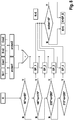
- FIG. 4 shows the signal processing of the signals of two magnetic field sensors 5, 6, which each have two sensor units (not shown).
- a sinusoidal signal sin1 or sin2 and a cosine signal cos1 or cos2 are respectively generated in a sensory region I.
- the sine and cosine signals of a respective sensor 5, 6 are converted in a signal processing unit II into a respective arctan signal arctan1 and arctan2, respectively.
- the respective signals are plotted over the angle.
- the arctangent signals become Difference signal ⁇ arctan generated, which is divided for a subsequent comparison in four contiguous sections K1, K2, K3, K4.
- the range limits substantially coincide with the steep edges of the difference signal ⁇ arctan. These signal ranges are compared (for example, based on (for example, summing) a predefined number of sampling values) with predefined references and thus used for assignment to a mechanical absolute angle of the shaft.
- FIG. 5 shows a representation of the two arctan functions arctan1, arctan2, as in the signal processing area II in FIG. 4 have been presented. Specifically, the electrical angle ⁇ E is plotted against the mechanical angle ⁇ M. The deviation of the two arctangent functions, which results from the apparent small difference ⁇ ⁇ E , is reported in FIG. 6 for the four signal ranges K1, K2, K3, K4 applied over the mechanical angle ⁇ M.
- FIG. 6 shows a representation of the difference ⁇ ⁇ E of in FIG. 5 shown arctan functions arctan1, arctan2 over the mechanical angle ⁇ M.
- Each of the signal areas K1, K2, K3, K4 has two peaks whose relative position and / or amplitude and amplitude differ from the corresponding peak of each other area K1, K2, K3, K4. Accordingly, it is possible to determine the signals of the regions K1, K2, K3, K4 with corresponding stored references (eg by calculating a mathematical distance of the signal regions from the references) and to use them for angle determination.
- the main physical effects that are useful are magnetic errors, such as pole width variation and inhomogeneity of the ring magnet, which are different from pole pair to pole pair.
- each sensor is located on two different poles / pole pairs at the same time.
- four values can be calculated that are unique to the respective pole pair. These values are used to calculate a correction of the angular content.
- the arctangent angle is added to the expression x • (360 ° / magnet pole pair number).
- the addition takes place in each case at the sign change of the angle signal.
- the multiplier x is determined by the calculated characteristic.
- the characteristic (K1) for an eight-pole magnet in the range between 0 ° and 90 ° is interpreted as the value 0 for x. For the range 90 ° to 180 ° the value is 1, for the range 180 ° to 270 ° the value is 2 and for the range 270 ° to 360 ° the value is 3. In this way one obtains an unambiguous angle signal.
- FIG. 7 describes the calculation of the result angle by the correction of the arctangent signal of a magnetic field sensor 5, 6.
- the arctan signal arctan1 of the first magnetic field sensor 5 is plotted as a sawtooth-shaped signal over the mechanical angle ⁇ M.
- the in FIG. 7 Correction signal Korr added added, resulting in the shaft of the mechanically absolute angle ⁇ Mres .
- the sensor system therefore needs a "teach-in phase" to generate the correction signal Korr, which corresponds to the Figures 5/6 will be charged.
- the result angle (mechanically absolute angle) is thus obtained by using the correction signal Korr for the arctangent course of the signal of a magnetic field sensor.
- FIG. 8 shows a flowchart for collecting the correction signal from the four sensor signals sin1, cos1, sin2, cos2 and a reference signal x.
- the magnetic field sensors sin1, cos1, sin2, cos2 are detected by the magnetic field sensors, then the arctan signals arctan1, arctan2 determined and then subtracted from each other.
- the reference angle x ie the mechanical angle ⁇ M of the shaft
- the difference signal of the arctangent signals and the reference angle x becomes a first one arctan1 is less than 0 °.
- the inventive concept can for example provide a defined distance of the magnetic field sensors from one another and a defined distance of the magnetic field sensors to the magnetic ring (also called “magnetic ring").
- the sensor system is arbitrarily variable in terms of the number of magnetic poles and in terms of the angle between the magnetic field sensors.
- a possible parameter for the functionality of the device is the fulfillment of the specification of the magnetic field sensors according to the respective data sheet.
- the concept may provide an angle between the magnetic field sensors corresponding to the number of pole pairs (e.g., 360 ° / pole pair number) between the sensors and use an air gap between the magnetic rim and the magnetic field sensors of 2mm. In this way, the rotating magnetic ring generates a periodic, sinusoidal waveform at the magnetic field sensors.
- the invention thus represents an alternative concept to the axial angle sensor.
- the installation position in the azimuthal direction is relatively arbitrary, since a mechanical absolute angle measurement takes place.
- costs can be reduced by using inexpensive sensors and mass by magnetic rings of molded Hartferrittechnikstoff.
- the possibility of a learning process for the device according to the invention high installation tolerances can be accepted, thereby simplifying the production.
- the small magnets and magnetic field sensors also require a small space requirement.
- the sensors on the electronics motherboard of the rotary machine can be arranged with a recess for the motor shaft, whereby additional cost savings and component variety reduction is possible.
- a speed and rotational speed measurement is possible by a device according to the invention.
- the angle determination is to be evaluated on the basis of a time signal.
Description
Die vorliegende Erfindung betrifft ein Fahrzeug, eine Rotationsmaschine sowie eine Vorrichtung zur mechanisch absoluten Winkelbestimmung einer Welle einer Rotationsmaschine. Insbesondere betrifft die vorliegende Erfindung ein kostengünstiges Sensorkonzept zur Rotorlagebestimmung, welches zudem eine einfache flexible Konstruktion ermöglicht.The present invention relates to a vehicle, a rotary machine and a device for the mechanical absolute angle determination of a shaft of a rotary machine. In particular, the present invention relates to a low-cost sensor concept for rotor position determination, which also allows a simple flexible construction.
Für die Ansteuerung und Regelung von EC-Motoren in der Automobilelektronik sowie in elektrisch antreibbaren Fortbewegungsmitteln (z.B. Pedelecs und E-Bikes) wird je nach Motoransteuerung eine Rotorlageinformation benötigt. Diese wird anhand einer Winkelposition, in welcher sich die Motorwelle befindet, ermittelt. Der Winkel muss je nach Anforderung des Produktes mit einer hohen Genauigkeit (kleiner 0,5°) gemessen werden. Es wird unterschieden zwischen elektrisch absoluter und mechanisch absoluter Winkelmessung. Bei der elektrisch absoluten Winkelmessung wird nur die Winkelveränderung innerhalb eines Polpaarwechsels des Motors betrachtet. Bei der mechanisch absoluten Winkelmessung wird eine Winkelveränderung über 360° der Motorwelle (unabhängig von der Anzahl von Motorpolen) festgestellt.Depending on the motor control, rotor position information is required for the control and regulation of EC motors in automotive electronics as well as in electrically propelled means of locomotion (for example pedelecs and e-bikes). This is determined by an angular position in which the motor shaft is located. Depending on the requirements of the product, the angle must be measured with a high degree of accuracy (less than 0.5 °). A distinction is made between electrically absolute and mechanically absolute angle measurement. In the case of the electrically absolute angle measurement, only the angle change within a pole pair change of the motor is considered. In the case of the mechanical absolute angle measurement, an angle change over 360 ° of the motor shaft is detected (regardless of the number of motor poles).
Aktuell werden hauptsächlich mechanisch absolute Sensorsysteme in Produkten wie Wischersystemen, elektrisch antreibbaren Fahrrädern oder elektrischen Stellern eingesetzt. Bei der mechanisch absoluten Winkelmessung wird der Winkel überwiegend über magnetoresistive Sensorsysteme gemessen. Das Sensorsystem besteht aus einem Sensormagneten (Magnetfeldgeber) und einem magnetoresistiven Sensor (wie z.B. AMR, GMR oder TMR). Diese Systeme sind axial ausgelegt, d.h., der Sensormagnet wird am Motorwellenende axial befestigt. Der Sensor wird dabei üblicherweise parallel zum Sensormagneten positioniert. Auf einen derartigen Aufbau wird in Verbindung mit
Es ist eine Aufgabe der vorliegenden Erfindung, ein alternatives, kostengünstiges Sensorkonzept zur aktuellen axialen Rotorlagebestimmung aufzuzeigen. Insbesondere sollen derart ausgestattete Produkte mit einer Motorsteuerelektronik parallel zur Motorwelle ausgestattet werden können. Insbesondere soll eine kostengünstige, mechanisch absolute Winkelmessung mit einer Messungenauigkeit kleiner als 1% ermöglicht werden.It is an object of the present invention to provide an alternative, cost-effective sensor concept for current axial rotor position determination. In particular, such products should be equipped with a motor control electronics parallel to the motor shaft. In particular, a cost-effective, mechanically absolute angle measurement with a measurement inaccuracy of less than 1% is to be made possible.
Die vorstehend identifizierte Aufgabe wird erfindungsgemäß durch eine Vorrichtung zur mechanisch absoluten Winkelbestimmung einer Welle einer Rotationsmaschine gemäß Anspruch 1 gelöst. Die Vorrichtung umfasst einen Magnetkranz mit einer Vielzahl magnetischer Pole. Der Magnetkranz dient insbesondere ausschließlich der Winkelbestimmung und kann bevorzugt (ausschließlich) Permanentmagneten umfassen. Zusätzlich sind ein erster Magnetfeldsensor und ein zweiter Magnetfeldsensor sowie eine Auswerteeinheit vorgesehen. Der Magnetkranz ist eingerichtet, insbesondere in azimutaler Erstreckungsrichtung an/auf der Welle der Rotationsmaschine (z.B. ein Elektromotor, ein elektrischer Generator o.Ä.) angeordnet zu werden. Die Magnetfeldsensoren sind eingerichtet, die Magnetfelder, welche durch den Magnetkranz bereitgestellt werden, zu detektieren, wenn sie sich im Zuge einer Rotation der Welle an den Magnetfeldsensoren vorbeibewegen. Die Auswerteeinheit ist eingerichtet, auf Magnetfeldsignalen der Magnetfeldsensoren basierende Signale miteinander zu vergleichen. Mit anderen Worten liefern die von den Magnetfeldsensoren bereitgestellten elektrischen Signale Informationen, auf Basis welcher die Auswerteeinheit einen Vergleich ausführt. Eine Vorverarbeitung der elektrischen Signale der Magnetfeldsensoren ist also ausdrücklich als im Rahmen der vorliegenden Erfindung möglich zu betrachten. Eine eindeutige Zuordnung von Eigenschaften der analysierten Signale zu einer mechanisch absoluten Winkelposition erfolgt erfindungsgemäß durch die Identifikation fertigungsbedingter Unregelmäßigkeiten des Magnetkranzes bzw. seiner magnetischen Pole (z.B. in azimutaler Richtung (Drehrichtung) verteilte Streuungen o.Ä.), um anhand identifizierter Unregelmäßigkeiten eine mechanisch absolute Winkelbestimmung der Welle vorzunehmen. Im Unterschied zum Stand der Technik wird durch die Verwendung zweier Sensoren an ein und demselben Magnetkranz eine derart differenzierte Untersuchung der Magnetfelder möglich, dass sozusagen ein "magnetischer Fingerabdruck" des Magnetkranzexemplars erstellt und mit einer vordefinierten Referenz verglichen werden kann. Auf Basis der Referenz können die von den Magnetfeldsensoren erzeugten Signale somit zur Bestimmung einer mechanisch absoluten Winkelposition der Welle verwendet werden. Im Stand der Technik übliche Aufwände zur mechanisch absoluten Winkelbestimmung können daher erfindungsgemäß entfallen. Zudem ermöglicht die radiale Anordnung der Sensoren einen einfachen Aufbau der erfindungsgemäßen Vorrichtung und somit eine kostengünstige und bauraumoptimierte Auslegung entsprechend ausgestatteter Rotationsmaschinen.The above-identified object is achieved by a device for mechanically absolute angle determination of a shaft of a rotary machine according to
Die Auswerteeinheit der erfindungsgemäßen Vorrichtung ist weiter eingerichtet die Signale der Magnetfeldsensoren dadurch miteinander zu vergleichen, dass sie eine Differenz zwischen einem Signal des ersten Magnetfeldsensors und einem Signal des zweiten Magnetfeldsensors bildet. Sowohl das Signal des ersten Magnetfeldsensors als auch das Signal des zweiten Magnetfeldsensors kann jeweils auf einer Vielzahl einzelner Signale basieren und durch deren Kombination erzeugt werden. Hierzu können beispielsweise mehrere Sensorköpfe oder Sensoreinheiten in den verwendeten Magnetfeldsensoren vorgesehen sein. Durch die Differenz werden identische Anteile in den Sensorsignalen unterdrückt und fertigungsbedingte Unregelmäßigkeiten des Magnetkranzes treten besonders günstig in Erscheinung.The evaluation unit of the device according to the invention is further configured to compare the signals of the magnetic field sensors with each other by forming a difference between a signal of the first magnetic field sensor and a signal of the second magnetic field sensor. Both the signal of The first magnetic field sensor as well as the signal of the second magnetic field sensor can each be based on a multiplicity of individual signals and generated by their combination. For this purpose, for example, a plurality of sensor heads or sensor units may be provided in the magnetic field sensors used. Due to the difference identical components are suppressed in the sensor signals and production-related irregularities of the magnetic ring occur particularly favorable in appearance.
Der erste Magnetfeldsensor wird erfindungsgemäß zwei Signale abgeben, wobei eine Phasenverschiebung zwischen dem ersten Magnetfeldsignal und dem zweiten Magnetfeldsignal existieren kann. Weisen die Magnetfeldsignale im Wesentlichen die Eigenschaften einer Sinusfunktion bzw. einer Cosinus-Funktion auf, können aus beiden Magnetfeldsignalen in besonders einfacher Weise Arkustangens-Funktionen erstellt/errechnet werden, welche eine im Wesentlichen abschnittsweise lineare Abbildung des Winkels der Rotationsmaschine bzw. ihrer Welle darstellen. Entsprechendes gilt für ein drittes bzw. ein viertes Magnetfeldsignal, welche von dem zweiten Magnetfeldsensor erzeugt werden. Erfindungsgemäß werden die wie zuvor beschrieben erzeugten Arkustangens-Funktionen des ersten Magnetfeldsensors bzw. der zweiten Magnetfeldsensors voneinander abgezogen um aus dem Sensorsignal ein Winkelsignal zu generieren. Dieser Winkel ist eindeutig über ein Magnetpolpaar des Ringmagneten (elektrisch absoluter Winkel). Um aus dem eindeutigen Winkel über ein Polpaar des Magneten ein eindeutiges Winkelsignal über 360° mechanischer Umdrehung des Magneten zu erhalten, wird die Differenz der beiden Winkelsignale vom Sensor 1 und Sensor 2 gebildet. Das Differenzsignal ist nicht periodisch über die jeweiligen Polpaare und kann daher genutzt werden, um eine eindeutige Kenngröße für das jeweilige Magnetpolpaar zu erzeugen.According to the invention, the first magnetic field sensor will emit two signals, wherein a phase shift between the first magnetic field signal and the second magnetic field signal may exist. If the magnetic field signals essentially have the properties of a sine function or a cosine function, arctangent functions can be created / calculated from both magnetic field signals in a particularly simple manner, which represent a substantially section-wise linear representation of the angle of the rotary machine or its shaft. The same applies to a third or a fourth magnetic field signal, which are generated by the second magnetic field sensor. According to the invention, the arctangent functions of the first magnetic field sensor or of the second magnetic field sensor produced as described above are subtracted from one another in order to generate an angle signal from the sensor signal. This angle is clearly over a magnetic pole pair of the ring magnet (electrically absolute angle). In order to obtain from the unique angle over a pole pair of the magnet a clear angle signal over 360 ° mechanical rotation of the magnet, the difference between the two angle signals from the
Bevorzugt ist der Magnetkranz eingerichtet, die Welle der Rotationsmaschine in radialer Richtung zu umschließen. Mit anderen Worten erstreckt sich der Magnetkranz in azimutaler Richtung, um die Welle und ist insbesondere nicht an einer Stirnseite (einem Extrempunkt in axialer Richtung) angeordnet. Auf diese Weise können mit einer erfindungsgemäßen Vorrichtung ausgestattete Rotationsmaschinen eine kostengünstige und bauraumoptimierte Konstruktion erhalten.Preferably, the magnetic ring is adapted to enclose the shaft of the rotary machine in the radial direction. In other words, the magnetic ring extends in the azimuthal direction to the shaft and in particular is not arranged on one end face (an extreme point in the axial direction). In this way, rotary machines equipped with a device according to the invention can obtain a cost-effective and space-optimized construction.
Beispielsweise kann der Magnetkranz mindestens acht magnetische Pole aufweisen. Da in diesem Fall bei einer erfindungsgemäß nicht vorgesehenen idealen Magnetpolgestalt (100%-ige Homogenität der Magnetpole) jeweils zwei Magnetpolübergänge identische Signale liefern, kann eine erfindungsgemäße Vorrichtung fertigungsbedingte Unregelmäßigkeiten ausnutzen, um die im Wesentlichen identischen Magnetpolübergänge voneinander zu unterscheiden. Entsprechend kann eine kostengünstige Winkelbestimmung bei gleichzeitig hoher Winkelauflösung realisiert werden.For example, the magnetic ring may have at least eight magnetic poles. Since in this case an ideal magnetic pole shape (100% homogeneity of the magnetic poles) does not provide identical magnetic pole transitions in each case, a device according to the invention can utilize production-related irregularities in order to distinguish the substantially identical magnetic pole transitions from each other. Accordingly, a cost angle determination can be realized at the same time high angular resolution.
Der erste Magnetfeldsensor und der zweite Magnetfeldsensor sind bevorzugt an vordefinierten und bekannten Winkelpositionen in Rotationsrichtung zueinander angeordnet. Mit anderen Worten ist bekannt, um wieviel Grad in Drehrichtung die Position des ersten Magnetfeldsensors von der Position des zweiten Magnetfeldsensors abweicht. Auf diese Weise kann eine rasche und kostengünstige Überführung der Signale des ersten Magnetfeldsensors in das Koordinatensystem des zweiten Magnetfeldsensors (oder umgekehrt) erfolgen. Entsprechend können auch feine Unregelmäßigkeiten, welche sich im Differenzsignal zwischen dem Signal des ersten Magnetfeldsensors und dem Signal des zweiten Magnetfeldsensors wiederfinden, zur Winkelbestimmung aufgelöst werden.The first magnetic field sensor and the second magnetic field sensor are preferably arranged at predefined and known angular positions in the direction of rotation relative to one another. In other words, it is known how many degrees in the direction of rotation the position of the first magnetic field sensor deviates from the position of the second magnetic field sensor. In this way, a rapid and cost-effective transfer of the signals of the first magnetic field sensor in the coordinate system of the second magnetic field sensor (or vice versa) take place. Accordingly, even fine irregularities, which are found in the difference signal between the signal of the first magnetic field sensor and the signal of the second magnetic field sensor, can be resolved for angle determination.
In der vorgenannten Anordnung können die beiden Magnetfeldsensoren selbstverständlich auch an ein und derselben Winkelposition angeordnet sein.In the aforementioned arrangement, the two magnetic field sensors can of course also be arranged at one and the same angular position.
Insbesondere können die Signale auch schaltungstechnisch und/oder unter Vermittlung digitaler Signalverarbeitung zueinander verschoben werden, um ein geeignetes Differenzsignal zu erzeugen. Insbesondere können sich durch die Verschiebung der Arkustangens-Funktionen gegeneinander ergebenden Peaks in der Differenz als Signalbereichsgrenzen zum Vergleich des Signals mit abgespeicherten Referenzen verwendet werden.In particular, the signals can also be shifted to each other in circuit technology and / or by means of digital signal processing in order to generate a suitable difference signal. In particular, by shifting the arctangent functions against each other, peaks in the difference may be used as signal range boundaries for comparison of the signal with stored references.
Der erste Magnetfeldsensor und/oder der zweite Magnetfeldsensor kann bzw. können als Hall- und/oder XMR-Sensoren ausgestaltet sein. Die Verwendung eines oder mehrerer der vorgenannten Sensorprinzipien kann kostengünstig durch Standardelemente erfolgen und hat sich zudem in Versuchen bewährt.The first magnetic field sensor and / or the second magnetic field sensor can be configured as Hall and / or XMR sensors. The use of one or more of the aforementioned sensor principles can be done inexpensively by standard elements and has also been proven in tests.
Zur Winkelbestimmung der Welle kann die Auswerteeinheit eingerichtet sein, eine Referenz (z.B. aus einem Datenspeicher) auszulesen, anhand welcher die identifizierten Unregelmäßigkeiten klassifiziert werden können. Mit anderen Worten wird der "magnetische Fingerabdruck" des Magnetkranzes ermittelt und mit Referenzen verglichen, welchen eine jeweilige Drehwinkelposition der Welle zugeordnet ist. Beispielsweise durch die mathematische Bestimmung eines Abstandes eines erfassten (vorverarbeiteten) Magnetsignals, welches insbesondere zwischen zwei steilen Flanken des Arkustangens-Signals auftritt, kann ein Vergleich mit den Referenzen angestellt werden und diejenige Winkelposition als aktuell vorliegend angenommen bzw. gemeldet werden, welche den geringsten ermittelten Abstand (z.B. mathematische Abweichung) aufweist.For determining the angle of the shaft, the evaluation unit can be set up to read out a reference (for example from a data memory), by means of which the identified irregularities can be classified. In other words, the "magnetic fingerprint" of the magnetic ring is determined and compared with references to which a respective rotational angular position of the shaft is assigned. For example, by the mathematical determination of a distance of a detected (preprocessed) magnetic signal, which occurs in particular between two steep edges of the arctangent signal, a comparison with the references can be made and the one angular position assumed to be the present case, which determined the lowest Distance (eg mathematical deviation).
Gemäß einem zweiten Aspekt der vorliegenden Erfindung wird eine Rotationsmaschine vorgeschlagen, welche eine Welle, ein Gehäuse und eine erfindungsgemäße Vorrichtung aufweist. Die Welle ist zumindest teilweise innerhalb einer Gehäusewandung des Gehäuses angeordnet. Bevorzugt durchragt die Welle die Gehäusewandung vollständig, während der Magnetkranz der Vorrichtung innerhalb des Gehäuses angeordnet ist. Mit anderen Worten befindet sich die erfindungsgemäße Vorrichtung im Bereich desjenigen Gehäusevolumens, in welchem auch die magnetisch relevanten Bauteile (z.B. Rotor und Stator) der Rotationsmaschine angeordnet sind. Auf diese Weise wird ein in azimutaler Richtung (also in Umfangsrichtung) erstreckter Magnetkranz für die erfindungsgemäße Winkelbestimmung der Rotationsmaschine verwendet. Diese ist besonders kostengünstig, ermöglicht eine flexible Gestalt der Rotationsmaschine und erfindungsgemäß dennoch eine Winkelbestimmung mit einer maximalen Toleranz kleiner 1°, insbesondere kleiner 0,5°.According to a second aspect of the present invention, a rotary machine is proposed, which has a shaft, a housing and a device according to the invention. The shaft is at least partially disposed within a housing wall of the housing. Preferably, the shaft extends through the housing wall completely, while the magnetic ring of the device is disposed within the housing. In other words, the device according to the invention is located in the region of that housing volume in which the magnetically relevant components (for example rotor and stator) of the rotary machine are also arranged. In this way, a magnetic rim extended in the azimuthal direction (ie in the circumferential direction) is used for the angle determination of the rotary machine according to the invention. This is particularly cost-effective, allows a flexible shape of the rotary machine and according to the invention nevertheless an angle determination with a maximum tolerance of less than 1 °, in particular less than 0.5 °.
Gemäß einem dritten Aspekt der vorliegenden Erfindung wird ein Fahrzeug vorgeschlagen, welches beispielsweise als elektrisch antreibbares Fahrrad (Pedelec, e-Bike o.Ä.) ausgestaltet ist. Zur Winkelbestimmung der Welle der Rotationsmaschine des Fahrzeugs, welche für regelungstechnische Vorgänge eine entscheidende Rolle spielt, wird eine erfindungsgemäße Vorrichtung bzw. eine erfindungsgemäße Rotationsmaschine vorgeschlagen. Es ergeben sich die Merkmale, Merkmalskombinationen und die Vorteile der vorgenannten Erfindungsaspekte entsprechend, so dass zur Vermeidung von Wiederholungen auf die obigen Ausführungen verwiesen wird.According to a third aspect of the present invention, a vehicle is proposed which is designed, for example, as an electrically drivable bicycle (pedelec, e-bike or the like). For determining the angle of the shaft of the rotary machine of the vehicle, which plays a decisive role for control processes, a device according to the invention or a rotary machine according to the invention is proposed. The features, feature combinations and the advantages of the aforementioned aspects of the invention result accordingly, so that reference is made to the above statements to avoid repetition.
Nachfolgend werden bevorzugte Ausführungsformen der vorliegenden Erfindung anhand der beigefügten Zeichnungen beschrieben. Es zeigen:
Figur 1- eine schematische Darstellung einer Rotationsmaschine mit einer in axialer Richtung angeordneten Winkelsensorik;
Figur 2- eine erfindungsgemäße Weiterbildung der in
Figur 1 - Figur 3
- eine alternative Darstellung einer erfindungsgemäßen Vorrichtung mit zwei separaten Magnetfeldsensorplatinen;
Figur 4- eine schematische Veranschaulichung der Signalverarbeitung in einem Ausführungsbeispiel einer erfindungsgemäßen Vorrichtung;
Figur 5- eine schematische Veranschaulichung der Signale zweier Magnetfeldsensoren (Arkustangens-Funktionen);
Figur 6- eine Darstellung eines magnetischen Fingerabdrucks (Arkustangens-Differenzsignal) der in
Figur 5 Figur 7- eine schematische Darstellung von Signalen zur erfindungsgemäßen Winkelbestimmung; und
- Figur 8
- ein alternatives Flussdiagramm zur Veranschaulichung einer Klassifikation ermittelter Arkustangens-Differenzsignale zur erfindungsgemäßen Winkelbestimmung.
- FIG. 1
- a schematic representation of a rotary machine with an arranged in the axial direction angle sensor;
- FIG. 2
- an inventive development of in
FIG. 1 arrangement shown; - FIG. 3
- an alternative illustration of a device according to the invention with two separate magnetic field sensor boards;
- FIG. 4
- a schematic illustration of the signal processing in an embodiment of a device according to the invention;
- FIG. 5
- a schematic illustration of the signals of two magnetic field sensors (arctangent functions);
- FIG. 6
- a representation of a magnetic fingerprint (arctangent difference signal) of
FIG. 5 shown time signals; - FIG. 7
- a schematic representation of signals for angle determination according to the invention; and
- FIG. 8
- an alternative flowchart for the purpose of illustrating a classification of determined arctangent difference signals for angle determination according to the invention.

Das Sensorsystem braucht daher eine "Einlernphase", um das Korrektursignal Korr zu erzeugen, welches entsprechend den
Das erfindungsgemäße Konzept kann beispielsweise einen definierten Abstand der Magnetfeldsensoren zueinander sowie einen definierten Abstand der Magnetfeldsensoren zum Magnetkranz (auch "Magnetring") vorsehen. Das Sensorsystem ist hinsichtlich der Anzahl der Magnetpole sowie hinsichtlich des Winkels zwischen den Magnetfeldsensoren beliebig variabel. Ein möglicher Parameter für die Funktionstüchtigkeit der Vorrichtung ist die Erfüllung der Spezifikation der Magnetfeldsensoren gemäß dem jeweiligen Datenblatt. Das Konzept kann beispielsweise einen Winkel zwischen den Magnetfeldsensoren entsprechend der Polpaarzahl (z.B. 360°/Polpaarzahl) zwischen den Sensoren vorsehen und einen Luftspalt zwischen dem Magnetkranz und den Magnetfeldsensoren von 2 mm verwenden. Auf diese Weise erzeugt der rotierende Magnetkranz einen periodischen, sinusähnlichen Signalverlauf an den Magnetfeldsensoren.The inventive concept can for example provide a defined distance of the magnetic field sensors from one another and a defined distance of the magnetic field sensors to the magnetic ring (also called "magnetic ring"). The sensor system is arbitrarily variable in terms of the number of magnetic poles and in terms of the angle between the magnetic field sensors. A possible parameter for the functionality of the device is the fulfillment of the specification of the magnetic field sensors according to the respective data sheet. For example, the concept may provide an angle between the magnetic field sensors corresponding to the number of pole pairs (e.g., 360 ° / pole pair number) between the sensors and use an air gap between the magnetic rim and the magnetic field sensors of 2mm. In this way, the rotating magnetic ring generates a periodic, sinusoidal waveform at the magnetic field sensors.
Die Erfindung stellt somit ein Alternativkonzept zur axialen Winkelsensorik dar. Die Einbauposition in azimutaler Richtung ist relativ beliebig, da eine mechanische Absolutwinkelmessung erfolgt. Zudem können Kosten durch Verwendung preiswerter Sensoren und Masse durch Magnetkränze aus gespritztem Hartferritwerkstoff verringert werden. Durch die Möglichkeit eines Einlernvorgangs für die erfindungsgemäße Vorrichtung können hohe Einbautoleranzen in Kauf genommen werden, wodurch sich die Fertigung vereinfacht. Die kleinen Magnete und Magnetfeldsensoren bedingen zudem einen geringen Bauraumbedarf. Beispielsweise können auch die Sensoren auf der Elektronik-Hauptplatine der Rotationsmaschine mit einer Aussparung für die Motorwelle angeordnet werden, wodurch eine zusätzliche Kostenersparnis und Bauteilvielzahlreduktion möglich ist. Auch eine Geschwindigkeits- und Drehzahlmessung ist durch eine erfindungsgemäße Vorrichtung möglich. Hierzu ist die Winkelbestimmung anhand eines Zeitsignals auszuwerten. Zudem ist eine Bestimmung des Absolutwinkels auch ohne eine Bewegung der Welle möglich, das (nach einem Einlernvorgang) ein eindeutiger Korrekturwert und -winkel vorliegt. Auch eine Temperaturkompensation ist durch die Verwendung zweier Sensoren möglich, wodurch auch eine Redundanz geschaffen wird.The invention thus represents an alternative concept to the axial angle sensor. The installation position in the azimuthal direction is relatively arbitrary, since a mechanical absolute angle measurement takes place. In addition, costs can be reduced by using inexpensive sensors and mass by magnetic rings of molded Hartferritwerkstoff. The possibility of a learning process for the device according to the invention high installation tolerances can be accepted, thereby simplifying the production. The small magnets and magnetic field sensors also require a small space requirement. For example, the sensors on the electronics motherboard of the rotary machine can be arranged with a recess for the motor shaft, whereby additional cost savings and component variety reduction is possible. A speed and rotational speed measurement is possible by a device according to the invention. For this purpose, the angle determination is to be evaluated on the basis of a time signal. In addition, a determination of the absolute angle is possible even without a movement of the shaft, which (after a teach-in process) a clear correction value and angle is present. Also, a temperature compensation is possible by the use of two sensors, whereby a redundancy is created.
Claims (9)
- Device for mechanically absolute angle determination of a shaft (2) of a rotary machine (3), comprising:- a magnetic ring (4) having a multiplicity of magnetic poles (N, S),- a first magnetic field sensor (5),- a second magnetic field sensor (6), and- an evaluation unit (8),where- the magnetic ring (4) is set up to be arranged on the shaft (2) of the rotary machine (3),- the magnetic field sensors (5) are set up to detect the magnetic fields of the poles of the magnetic ring (4) passing in the course of a rotation of the shaft (2), and- the evaluation unit (8) is set upcharacterized in that- to compare with one another signals based on magnetic field signals (sin1, cos1, sin2, cos2) from the magnetic field sensors (5),- to identify production-induced irregularities in the magnetic ring (4), and- to perform a mechanically absolute angle determination of the shaft (2) by using the identified irregularities,
the first magnetic field sensor (5) is set up to output a first magnetic field signal (sin1) and a second magnetic field signal (cos1), and
the second magnetic field sensor (6) is set up to output a third magnetic field signal (sin2) and a fourth magnetic field signal (cos2), wherein the first magnetic field signal (sin1) and the second magnetic field signal (cos1) and, respectively, the third magnetic field signal (sin2) and the fourth magnetic field signal (cos2) have a respective phase shift relative to each other, which is substantially 90°, and wherein
the evaluation unit (8) is set up to generate a respective arctan signal (arctan1, arctan2) from the first magnetic field signal (sin1) and the second magnetic field signal (cos1) and from the third magnetic field signal (sin2) and the fourth magnetic field signal (cos2), wherein the evaluation unit (8) is further set up to form a difference between the respective arctan signal from the first magnetic field sensor (5) and from the second magnetic field sensor (6) in order to compare the signals from the magnetic field sensors (5, 6). - Device according to one of the preceding claims, wherein the magnetic ring (4) is set up to enclose the shaft (2) in the radial direction.
- Device according to one of the preceding claims, wherein the magnetic ring (4) has eight magnetic poles (N, S).
- Device according to one of the preceding claims, wherein the first magnetic field sensor (5) and the second magnetic field sensor (6) are arranged in relation to each other at a predefined and in particular known angle (ϑ) in the direction of rotation (P).
- Device according to one of the preceding claims, wherein the first magnetic field sensor (5) and/or the second magnetic field sensor (6) is or are configured as Hall, AMR, GMR, TMR or XMR sensors.
- Device according to one of the preceding claims, wherein the evaluation unit (8) is further set up to read a reference (K1, K2, K3, K4) in order to perform an angle determination of the shaft (2) by using the identified irregularity.
- Device according to one of the preceding claims, wherein the evaluation unit (8) is set up- to evaluate a predetermined multiplicity of values within predetermined ranges of the magnetic field signals or the signals from the magnetic field sensors (5, 6), and- to compare the result of the evaluation with an association between a mechanical angle of the shaft (2) and predefined signals from the magnetic field sensors (5, 6).
- Rotary machine (10) comprising- a shaft (2),- a housing (11) and- a device (1) according to one of the preceding claims, wherein- the shaft (2) projects through at least part of a housing wall of the housing (11), and- the magnetic ring (4) of the device is arranged inside the housing (11).
- Vehicle, in particular electrically driven bicycle, comprising a device (4) according to one of the preceding Claims 1 to 7 or a rotary machine (3) according to Claim 8.
Applications Claiming Priority (1)
| Application Number | Priority Date | Filing Date | Title |
|---|---|---|---|
| DE102014224961.9A DE102014224961A1 (en) | 2014-12-05 | 2014-12-05 | Device and Algorythmik for the radial mechanical absolute angle determination of a wave |
Publications (2)
| Publication Number | Publication Date |
|---|---|
| EP3029427A1 EP3029427A1 (en) | 2016-06-08 |
| EP3029427B1 true EP3029427B1 (en) | 2017-09-13 |
Family
ID=54783401
Family Applications (1)
| Application Number | Title | Priority Date | Filing Date |
|---|---|---|---|
| EP15197409.4A Active EP3029427B1 (en) | 2014-12-05 | 2015-12-02 | Device and algorithm for radial mechanically absolute angle determination for a shaft |
Country Status (2)
| Country | Link |
|---|---|
| EP (1) | EP3029427B1 (en) |
| DE (1) | DE102014224961A1 (en) |
Families Citing this family (9)
| Publication number | Priority date | Publication date | Assignee | Title |
|---|---|---|---|---|
| GB2552385B (en) * | 2016-07-22 | 2021-09-15 | Cmr Surgical Ltd | Calibrating position sensor readings |
| DE102016226293A1 (en) * | 2016-12-29 | 2018-07-05 | Robert Bosch Gmbh | Brushless electric machine |
| CN110601609A (en) * | 2018-06-12 | 2019-12-20 | 舍弗勒技术股份两合公司 | Position detection system of automobile motor and automobile |
| DE102020105256A1 (en) | 2020-02-28 | 2021-09-02 | Schaeffler Technologies AG & Co. KG | Method for determining a rotational angle position of a shaft; Measuring arrangement; as well as actuator with measuring arrangement |
| DE102020105253A1 (en) | 2020-02-28 | 2021-09-02 | Schaeffler Technologies AG & Co. KG | Method for determining an angular position of a shaft in the presence of an interference field |
| DE102020105254A1 (en) | 2020-02-28 | 2021-09-02 | Schaeffler Technologies AG & Co. KG | Method for determining an angular position of a shaft |
| DE102020107229A1 (en) | 2020-03-17 | 2021-09-23 | Balluff Gmbh | Method for operating an absolute measuring position detection system with a single-track magnetic code object |
| DE102020133150A1 (en) | 2020-11-09 | 2022-05-12 | TDK Europe GmbH | Angle determination component and method |
| DE102021005044A1 (en) | 2021-10-08 | 2023-04-13 | Baumer Germany Gmbh & Co. Kg | Measurement data processor, position measuring device and computer-implemented method |
Family Cites Families (8)
| Publication number | Priority date | Publication date | Assignee | Title |
|---|---|---|---|---|
| DE10062223A1 (en) * | 2000-12-13 | 2002-06-20 | Zahnradfabrik Friedrichshafen | Determination of rotational velocity of a motor-vehicle gear shaft and its angular position by use of a magnetic signaling ring arranged around the shaft with a corresponding sensor |
| WO2006035055A2 (en) * | 2004-09-30 | 2006-04-06 | Continental Teves Ag & Co. Ohg | Magnetic absolute position sensor featuring a variable length of the individual encoding segments |
| DE102006033525A1 (en) * | 2005-07-26 | 2007-02-01 | Ebm-Papst St. Georgen Gmbh & Co. Kg | Electric motor with absolute encoder for generating absolute value for an angle of rotation comprises stator, rotor with sensor magnet and evaluation device which determines absolute value for rotational position of rotor |
| DE102006051720A1 (en) * | 2006-03-02 | 2007-09-06 | Continental Teves Ag & Co. Ohg | Sensor arrangement for use in e.g. steering angle sensor system for motor vehicle, has magnetic field sensors that are shiftably arranged with respect to cylinder axis of encoder around defined angle amount to each other |
| DE102007008870A1 (en) * | 2007-02-21 | 2008-09-04 | Hl-Planar Technik Gmbh | Arrangement and method for the absolute determination of the linear position or the angular position expressed by an angle |
| JP5725377B2 (en) * | 2010-04-16 | 2015-05-27 | 株式会社ジェイテクト | Rotation angle detector |
| DE102010040861A1 (en) | 2010-09-16 | 2012-03-22 | Robert Bosch Gmbh | Electronically commutated electric motor with a rotor position sensor |
| DE102011079962A1 (en) | 2011-07-28 | 2013-01-31 | Robert Bosch Gmbh | Electric motor with a rotor position sensor |
-
2014
- 2014-12-05 DE DE102014224961.9A patent/DE102014224961A1/en not_active Withdrawn
-
2015
- 2015-12-02 EP EP15197409.4A patent/EP3029427B1/en active Active
Non-Patent Citations (1)
| Title |
|---|
| None * |
Also Published As
| Publication number | Publication date |
|---|---|
| DE102014224961A1 (en) | 2016-06-09 |
| EP3029427A1 (en) | 2016-06-08 |
Similar Documents
| Publication | Publication Date | Title |
|---|---|---|
| EP3029427B1 (en) | Device and algorithm for radial mechanically absolute angle determination for a shaft | |
| AT510377B1 (en) | METHOD AND EMBODIMENTS FOR THE ABSOLUTE POSITION DETERMINATION BY MEANS OF TWO HALL SENSORS | |
| DE102009044542B3 (en) | Rolling bearing with a sensor unit | |
| EP2929297B1 (en) | Sensor apparatus for determining at least one rotation property of a rotating element | |
| WO2019001811A1 (en) | Sensor system for determining at least one rotation characteristic of a rotating element | |
| EP3555571B1 (en) | Sensor system for determining at least one rotation property of an element rotating about at least one rotational axis | |
| DE102017113861A1 (en) | Angle sensor and angle sensor system | |
| EP3884239B1 (en) | Angle sensor with multipole magnet for motor vehicle steering | |
| DE102013224098A1 (en) | Sensor arrangement for detecting angles of rotation on a rotating component in a vehicle | |
| DE102018211216A1 (en) | Encoder wheel arrangement and method for determining an absolute angle position and a direction of rotation | |
| EP2597429B1 (en) | Method and assembly for determining the dynamic status of an electric motor | |
| EP3721175B1 (en) | Sensor system for determining at least one rotational property of an element rotating around at least one rotation axis | |
| DE102013207621A1 (en) | Angle measurement, in particular contactless, with individual sensors | |
| EP3833936B1 (en) | Sensor system for determining at least one rotation characteristic of a rotating element | |
| DE102016206773A1 (en) | Motor control electronics for a brushless DC motor | |
| WO2013072219A2 (en) | Control module for a drive motor | |
| WO2013092369A1 (en) | Apparatus and method for determining a position of an element | |
| WO2020030319A1 (en) | Sensor system for determining at least one rotation characteristic of a rotating element | |
| DE102018213649A1 (en) | Sensor system for determining at least one rotational property of a rotating element | |
| DE102017126271A1 (en) | Positioning of motors by means of capacitive measurement | |
| DE102018007952B4 (en) | Device for sensory detection of rotational movements | |
| DE102014224295B3 (en) | Angle sensor and arrangement for determining unbalance and / or load | |
| DE102021210255A1 (en) | Sensor device and method for detecting an angular position and/or a speed of a rotatable object | |
| EP3146297B1 (en) | Method for ascertaining a movement of an object | |
| DE102017221761A1 (en) | Sensor system for determining at least one rotational property of an element rotating about at least one axis of rotation |
Legal Events
| Date | Code | Title | Description |
|---|---|---|---|
| PUAI | Public reference made under article 153(3) epc to a published international application that has entered the european phase |
Free format text: ORIGINAL CODE: 0009012 |
|
| AK | Designated contracting states |
Kind code of ref document: A1 Designated state(s): AL AT BE BG CH CY CZ DE DK EE ES FI FR GB GR HR HU IE IS IT LI LT LU LV MC MK MT NL NO PL PT RO RS SE SI SK SM TR |
|
| AX | Request for extension of the european patent |
Extension state: BA ME |
|
| 17P | Request for examination filed |
Effective date: 20161208 |
|
| RBV | Designated contracting states (corrected) |
Designated state(s): AL AT BE BG CH CY CZ DE DK EE ES FI FR GB GR HR HU IE IS IT LI LT LU LV MC MK MT NL NO PL PT RO RS SE SI SK SM TR |
|
| GRAP | Despatch of communication of intention to grant a patent |
Free format text: ORIGINAL CODE: EPIDOSNIGR1 |
|
| INTG | Intention to grant announced |
Effective date: 20170616 |
|
| GRAS | Grant fee paid |
Free format text: ORIGINAL CODE: EPIDOSNIGR3 |
|
| GRAA | (expected) grant |
Free format text: ORIGINAL CODE: 0009210 |
|
| AK | Designated contracting states |
Kind code of ref document: B1 Designated state(s): AL AT BE BG CH CY CZ DE DK EE ES FI FR GB GR HR HU IE IS IT LI LT LU LV MC MK MT NL NO PL PT RO RS SE SI SK SM TR |
|
| REG | Reference to a national code |
Ref country code: GB Ref legal event code: FG4D Free format text: NOT ENGLISH |
|
| REG | Reference to a national code |
Ref country code: CH Ref legal event code: EP |
|
| REG | Reference to a national code |
Ref country code: IE Ref legal event code: FG4D Free format text: LANGUAGE OF EP DOCUMENT: GERMAN |
|
| REG | Reference to a national code |
Ref country code: AT Ref legal event code: REF Ref document number: 928606 Country of ref document: AT Kind code of ref document: T Effective date: 20171015 |
|
| REG | Reference to a national code |
Ref country code: DE Ref legal event code: R096 Ref document number: 502015001890 Country of ref document: DE |
|
| REG | Reference to a national code |
Ref country code: NL Ref legal event code: FP |
|
| REG | Reference to a national code |
Ref country code: LT Ref legal event code: MG4D |
|
| PG25 | Lapsed in a contracting state [announced via postgrant information from national office to epo] |
Ref country code: LT Free format text: LAPSE BECAUSE OF FAILURE TO SUBMIT A TRANSLATION OF THE DESCRIPTION OR TO PAY THE FEE WITHIN THE PRESCRIBED TIME-LIMIT Effective date: 20170913 Ref country code: SE Free format text: LAPSE BECAUSE OF FAILURE TO SUBMIT A TRANSLATION OF THE DESCRIPTION OR TO PAY THE FEE WITHIN THE PRESCRIBED TIME-LIMIT Effective date: 20170913 Ref country code: HR Free format text: LAPSE BECAUSE OF FAILURE TO SUBMIT A TRANSLATION OF THE DESCRIPTION OR TO PAY THE FEE WITHIN THE PRESCRIBED TIME-LIMIT Effective date: 20170913 Ref country code: NO Free format text: LAPSE BECAUSE OF FAILURE TO SUBMIT A TRANSLATION OF THE DESCRIPTION OR TO PAY THE FEE WITHIN THE PRESCRIBED TIME-LIMIT Effective date: 20171213 Ref country code: FI Free format text: LAPSE BECAUSE OF FAILURE TO SUBMIT A TRANSLATION OF THE DESCRIPTION OR TO PAY THE FEE WITHIN THE PRESCRIBED TIME-LIMIT Effective date: 20170913 |
|
| PG25 | Lapsed in a contracting state [announced via postgrant information from national office to epo] |
Ref country code: GR Free format text: LAPSE BECAUSE OF FAILURE TO SUBMIT A TRANSLATION OF THE DESCRIPTION OR TO PAY THE FEE WITHIN THE PRESCRIBED TIME-LIMIT Effective date: 20171214 Ref country code: ES Free format text: LAPSE BECAUSE OF FAILURE TO SUBMIT A TRANSLATION OF THE DESCRIPTION OR TO PAY THE FEE WITHIN THE PRESCRIBED TIME-LIMIT Effective date: 20170913 Ref country code: RS Free format text: LAPSE BECAUSE OF FAILURE TO SUBMIT A TRANSLATION OF THE DESCRIPTION OR TO PAY THE FEE WITHIN THE PRESCRIBED TIME-LIMIT Effective date: 20170913 Ref country code: BG Free format text: LAPSE BECAUSE OF FAILURE TO SUBMIT A TRANSLATION OF THE DESCRIPTION OR TO PAY THE FEE WITHIN THE PRESCRIBED TIME-LIMIT Effective date: 20171213 Ref country code: LV Free format text: LAPSE BECAUSE OF FAILURE TO SUBMIT A TRANSLATION OF THE DESCRIPTION OR TO PAY THE FEE WITHIN THE PRESCRIBED TIME-LIMIT Effective date: 20170913 |
|
| PG25 | Lapsed in a contracting state [announced via postgrant information from national office to epo] |
Ref country code: CZ Free format text: LAPSE BECAUSE OF FAILURE TO SUBMIT A TRANSLATION OF THE DESCRIPTION OR TO PAY THE FEE WITHIN THE PRESCRIBED TIME-LIMIT Effective date: 20170913 Ref country code: RO Free format text: LAPSE BECAUSE OF FAILURE TO SUBMIT A TRANSLATION OF THE DESCRIPTION OR TO PAY THE FEE WITHIN THE PRESCRIBED TIME-LIMIT Effective date: 20170913 Ref country code: PL Free format text: LAPSE BECAUSE OF FAILURE TO SUBMIT A TRANSLATION OF THE DESCRIPTION OR TO PAY THE FEE WITHIN THE PRESCRIBED TIME-LIMIT Effective date: 20170913 |
|
| PG25 | Lapsed in a contracting state [announced via postgrant information from national office to epo] |
Ref country code: SM Free format text: LAPSE BECAUSE OF FAILURE TO SUBMIT A TRANSLATION OF THE DESCRIPTION OR TO PAY THE FEE WITHIN THE PRESCRIBED TIME-LIMIT Effective date: 20170913 Ref country code: IT Free format text: LAPSE BECAUSE OF FAILURE TO SUBMIT A TRANSLATION OF THE DESCRIPTION OR TO PAY THE FEE WITHIN THE PRESCRIBED TIME-LIMIT Effective date: 20170913 Ref country code: IS Free format text: LAPSE BECAUSE OF FAILURE TO SUBMIT A TRANSLATION OF THE DESCRIPTION OR TO PAY THE FEE WITHIN THE PRESCRIBED TIME-LIMIT Effective date: 20180113 Ref country code: EE Free format text: LAPSE BECAUSE OF FAILURE TO SUBMIT A TRANSLATION OF THE DESCRIPTION OR TO PAY THE FEE WITHIN THE PRESCRIBED TIME-LIMIT Effective date: 20170913 Ref country code: SK Free format text: LAPSE BECAUSE OF FAILURE TO SUBMIT A TRANSLATION OF THE DESCRIPTION OR TO PAY THE FEE WITHIN THE PRESCRIBED TIME-LIMIT Effective date: 20170913 |
|
| REG | Reference to a national code |
Ref country code: DE Ref legal event code: R097 Ref document number: 502015001890 Country of ref document: DE |
|
| PLBE | No opposition filed within time limit |
Free format text: ORIGINAL CODE: 0009261 |
|
| STAA | Information on the status of an ep patent application or granted ep patent |
Free format text: STATUS: NO OPPOSITION FILED WITHIN TIME LIMIT |
|
| PG25 | Lapsed in a contracting state [announced via postgrant information from national office to epo] |
Ref country code: DK Free format text: LAPSE BECAUSE OF FAILURE TO SUBMIT A TRANSLATION OF THE DESCRIPTION OR TO PAY THE FEE WITHIN THE PRESCRIBED TIME-LIMIT Effective date: 20170913 |
|
| 26N | No opposition filed |
Effective date: 20180614 |
|
| REG | Reference to a national code |
Ref country code: IE Ref legal event code: MM4A |
|
| PG25 | Lapsed in a contracting state [announced via postgrant information from national office to epo] |
Ref country code: LU Free format text: LAPSE BECAUSE OF NON-PAYMENT OF DUE FEES Effective date: 20171202 Ref country code: MT Free format text: LAPSE BECAUSE OF FAILURE TO SUBMIT A TRANSLATION OF THE DESCRIPTION OR TO PAY THE FEE WITHIN THE PRESCRIBED TIME-LIMIT Effective date: 20170913 |
|
| REG | Reference to a national code |
Ref country code: FR Ref legal event code: ST Effective date: 20180831 |
|
| REG | Reference to a national code |
Ref country code: BE Ref legal event code: MM Effective date: 20171231 |
|
| PG25 | Lapsed in a contracting state [announced via postgrant information from national office to epo] |
Ref country code: IE Free format text: LAPSE BECAUSE OF NON-PAYMENT OF DUE FEES Effective date: 20171202 Ref country code: FR Free format text: LAPSE BECAUSE OF NON-PAYMENT OF DUE FEES Effective date: 20180102 |
|
| PG25 | Lapsed in a contracting state [announced via postgrant information from national office to epo] |
Ref country code: BE Free format text: LAPSE BECAUSE OF NON-PAYMENT OF DUE FEES Effective date: 20171231 Ref country code: SI Free format text: LAPSE BECAUSE OF FAILURE TO SUBMIT A TRANSLATION OF THE DESCRIPTION OR TO PAY THE FEE WITHIN THE PRESCRIBED TIME-LIMIT Effective date: 20170913 |
|
| PG25 | Lapsed in a contracting state [announced via postgrant information from national office to epo] |
Ref country code: MC Free format text: LAPSE BECAUSE OF FAILURE TO SUBMIT A TRANSLATION OF THE DESCRIPTION OR TO PAY THE FEE WITHIN THE PRESCRIBED TIME-LIMIT Effective date: 20170913 Ref country code: HU Free format text: LAPSE BECAUSE OF FAILURE TO SUBMIT A TRANSLATION OF THE DESCRIPTION OR TO PAY THE FEE WITHIN THE PRESCRIBED TIME-LIMIT; INVALID AB INITIO Effective date: 20151202 |
|
| PG25 | Lapsed in a contracting state [announced via postgrant information from national office to epo] |
Ref country code: CY Free format text: LAPSE BECAUSE OF FAILURE TO SUBMIT A TRANSLATION OF THE DESCRIPTION OR TO PAY THE FEE WITHIN THE PRESCRIBED TIME-LIMIT Effective date: 20170913 |
|
| PG25 | Lapsed in a contracting state [announced via postgrant information from national office to epo] |
Ref country code: MK Free format text: LAPSE BECAUSE OF FAILURE TO SUBMIT A TRANSLATION OF THE DESCRIPTION OR TO PAY THE FEE WITHIN THE PRESCRIBED TIME-LIMIT Effective date: 20170913 |
|
| PG25 | Lapsed in a contracting state [announced via postgrant information from national office to epo] |
Ref country code: TR Free format text: LAPSE BECAUSE OF FAILURE TO SUBMIT A TRANSLATION OF THE DESCRIPTION OR TO PAY THE FEE WITHIN THE PRESCRIBED TIME-LIMIT Effective date: 20170913 |
|
| PG25 | Lapsed in a contracting state [announced via postgrant information from national office to epo] |
Ref country code: PT Free format text: LAPSE BECAUSE OF FAILURE TO SUBMIT A TRANSLATION OF THE DESCRIPTION OR TO PAY THE FEE WITHIN THE PRESCRIBED TIME-LIMIT Effective date: 20170913 |
|
| PG25 | Lapsed in a contracting state [announced via postgrant information from national office to epo] |
Ref country code: AL Free format text: LAPSE BECAUSE OF FAILURE TO SUBMIT A TRANSLATION OF THE DESCRIPTION OR TO PAY THE FEE WITHIN THE PRESCRIBED TIME-LIMIT Effective date: 20170913 |
|
| GBPC | Gb: european patent ceased through non-payment of renewal fee |
Effective date: 20191202 |
|
| PG25 | Lapsed in a contracting state [announced via postgrant information from national office to epo] |
Ref country code: GB Free format text: LAPSE BECAUSE OF NON-PAYMENT OF DUE FEES Effective date: 20191202 |
|
| PGFP | Annual fee paid to national office [announced via postgrant information from national office to epo] |
Ref country code: CH Payment date: 20230103 Year of fee payment: 8 |
|
| PGFP | Annual fee paid to national office [announced via postgrant information from national office to epo] |
Ref country code: DE Payment date: 20230223 Year of fee payment: 8 |
|
| PGFP | Annual fee paid to national office [announced via postgrant information from national office to epo] |
Ref country code: NL Payment date: 20231219 Year of fee payment: 9 Ref country code: AT Payment date: 20231214 Year of fee payment: 9 |