EP2884238A1 - Inductive rotation angle sensor with a circular segment shaped excitation and receiver coil - Google Patents
Inductive rotation angle sensor with a circular segment shaped excitation and receiver coil Download PDFInfo
- Publication number
- EP2884238A1 EP2884238A1 EP14197736.3A EP14197736A EP2884238A1 EP 2884238 A1 EP2884238 A1 EP 2884238A1 EP 14197736 A EP14197736 A EP 14197736A EP 2884238 A1 EP2884238 A1 EP 2884238A1
- Authority
- EP
- European Patent Office
- Prior art keywords
- angle
- rotation sensor
- coil
- voltage
- winding
- Prior art date
- Legal status (The legal status is an assumption and is not a legal conclusion. Google has not performed a legal analysis and makes no representation as to the accuracy of the status listed.)
- Ceased
Links
- 230000005284 excitation Effects 0.000 title claims abstract description 18
- 230000001939 inductive effect Effects 0.000 title claims description 14
- 238000004804 winding Methods 0.000 claims description 56
- 230000000737 periodic effect Effects 0.000 claims description 6
- 239000004020 conductor Substances 0.000 description 6
- 238000011156 evaluation Methods 0.000 description 4
- 239000003990 capacitor Substances 0.000 description 3
- 238000009434 installation Methods 0.000 description 2
- 241000826860 Trapezium Species 0.000 description 1
- 230000006978 adaptation Effects 0.000 description 1
- 238000010276 construction Methods 0.000 description 1
- 230000008878 coupling Effects 0.000 description 1
- 238000010168 coupling process Methods 0.000 description 1
- 238000005859 coupling reaction Methods 0.000 description 1
- 230000001419 dependent effect Effects 0.000 description 1
- 230000001771 impaired effect Effects 0.000 description 1
- 230000010355 oscillation Effects 0.000 description 1
- 230000010363 phase shift Effects 0.000 description 1
Images


Classifications
-
- G—PHYSICS
- G01—MEASURING; TESTING
- G01D—MEASURING NOT SPECIALLY ADAPTED FOR A SPECIFIC VARIABLE; ARRANGEMENTS FOR MEASURING TWO OR MORE VARIABLES NOT COVERED IN A SINGLE OTHER SUBCLASS; TARIFF METERING APPARATUS; MEASURING OR TESTING NOT OTHERWISE PROVIDED FOR
- G01D5/00—Mechanical means for transferring the output of a sensing member; Means for converting the output of a sensing member to another variable where the form or nature of the sensing member does not constrain the means for converting; Transducers not specially adapted for a specific variable
- G01D5/12—Mechanical means for transferring the output of a sensing member; Means for converting the output of a sensing member to another variable where the form or nature of the sensing member does not constrain the means for converting; Transducers not specially adapted for a specific variable using electric or magnetic means
- G01D5/14—Mechanical means for transferring the output of a sensing member; Means for converting the output of a sensing member to another variable where the form or nature of the sensing member does not constrain the means for converting; Transducers not specially adapted for a specific variable using electric or magnetic means influencing the magnitude of a current or voltage
- G01D5/20—Mechanical means for transferring the output of a sensing member; Means for converting the output of a sensing member to another variable where the form or nature of the sensing member does not constrain the means for converting; Transducers not specially adapted for a specific variable using electric or magnetic means influencing the magnitude of a current or voltage by varying inductance, e.g. by a movable armature
- G01D5/204—Mechanical means for transferring the output of a sensing member; Means for converting the output of a sensing member to another variable where the form or nature of the sensing member does not constrain the means for converting; Transducers not specially adapted for a specific variable using electric or magnetic means influencing the magnitude of a current or voltage by varying inductance, e.g. by a movable armature by influencing the mutual induction between two or more coils
Definitions
- the invention relates to a rotation angle sensor for detecting the angle of rotation of a rotating element according to the preamble of claim 1.
- an inductive position detector with a first inductive device and a second inductive device wherein the first inductive device comprises a passive resonant circuit and the second inductive device defines the measuring path and comprises at least two receiving windings.
- the second inductive device is configured to induce an alternating current in the passive resonant circuit in use such that the alternating current induced in the passive resonant circuit induces an alternating signal in each receive coil due to the mutual inductance between the receiving turns and the passive resonant circuit, indicative of these signals are for the position of the first inductive device on the measuring path.
- the invention is therefore based on the object to show a rotation angle sensor for detecting the rotation angle of a rotating element, which is as compact as possible executable.
- the invention is based on the basic idea of reducing the installation space through the design of the receiver coils along a circular segment. For measuring a rotation angle of the rotating element, therefore, a full circumference is not required for installation of the receiving coil. Instead, the receiving coil extends only over a part of a circumference or over a circle segment. Thus, the receiving coil can be made very compact and easier in small spaces, such as a motor integrated. It is advantageous to use two or more receiver coils. In the following description, reference will therefore be made to a plurality of receiving coils. Subsequent embodiments can in principle also be carried out with a receiver coil.
- the circular segment with the receiving coils was positioned variably relative to the entire circumference. It can be arranged at any part of a circumference.
- the exciter coil which is also executed on a circle segment. The unit of the receiving coil and the exciting coil therefore both occupy only the space on a circle segment.
- the angle encoder unit is connected to the rotating element, for example a shaft, and reflects the movement of the rotating element. By detecting the absolute position or the relative movement of the rotating element to the receiving coils, the rotational angle of the rotating element can be detected by means of the angle encoder unit either relative to the receiving coils or absolutely with respect to a reference point.
- the angle encoder unit is one of the exciter coil and the receiving coil separate part, which is, for example, arranged in parallel adjacent to the coils.
- An advantageous embodiment of the rotation angle sensor according to the invention is designed such that the circular segment extends substantially over an angle of about 360 ° / (2 * n), in particular 45 °, where n is an even number.
- the embodiment is particularly advantageous for use in combination with an electric motor having multiple pole pairs.
- the number of pole pairs can be used. For example, in an eight-pole motor, it is sufficient to arrange the exciting coil and the receiving coils over a circle segment extending over 45 °.
- An advantageous embodiment of the rotation angle sensor according to the invention is designed such that each receiving coil has a winding which has a periodic course.
- the windings of the receiver coils are arranged phase shifted from each other.
- An advantageous embodiment of the rotation angle sensor according to the invention is designed such that the winding has a plurality of winding sections which each define a measuring field bounded by winding sections.
- the measuring fields define individual essentially closed areas. The limits of such a range are defined by the respective winding sections.
- An advantageous embodiment of the rotation angle sensor according to the invention is designed such that the measuring fields are arranged uniformly spaced around a common point of rotation.
- An advantageous embodiment of the rotation angle sensor according to the invention is designed such that the winding has a substantially triangular or trapezoidal shape.
- An advantageous embodiment of the rotation angle sensor according to the invention is designed such that each receiving coil has winding sections which are arranged in different planes.
- the rotation angle sensor it is particularly advantageous to further develop the rotation angle sensor according to the invention such that the winding sections of the receiver coils are distributed substantially uniformly over two planes.
- the angle encoder unit is usually arranged parallel to the receiver coils. With this embodiment it is achieved that the winding sections of the receiving coils are each arranged alternately with a larger and a smaller distance to the angle encoder unit. The distance distribution from the windings of the receiving coils to the angle encoder unit is thereby divided equally. As a result, a qualitatively equivalent signal quality is achieved with both receiver coils.
- An advantageous embodiment of the rotation angle sensor according to the invention is designed such that the exciter coil and the receiver coils are arranged on a carrier body, which is formed in a circular segment.
- the carrier body may be formed, for example, as a printed circuit board.
- An advantageous embodiment of the rotation angle sensor according to the invention is designed such that the carrier body is annular. This embodiment allows a particularly compact design of the receiving coils and the exciter coil, in particular in connection with a carrier segment formed in the shape of a circle segment.
- An advantageous embodiment of the rotation angle sensor according to the invention is designed such that the angle encoder unit has an electronic resonant circuit with at least one capacitive and at least one inductive element.
- An advantageous embodiment of the rotation angle sensor according to the invention is designed such that the capacitive element is a capacitor and / or the inductive element is a current conductor.
- the capacitor and the inductive element may be embodied as printed on a printed circuit conductor or conductor tracks. This allows, in particular in connection with an annular carrier body of the angle encoder unit, a particularly variable utilization of the mounting surface on the carrier body.
- the shape of the oscillating circuits can be variably adapted to the respective requirements.
- An advantageous embodiment of the rotation angle sensor according to the invention is designed such that the angle encoder unit has a plurality of oscillating circuits.
- the embodiment is particularly useful when the sensor signals of the rotation angle sensor are used for controlling an electric motor, for example, a brushless DC motor.
- An advantageous embodiment of the rotation angle sensor according to the invention is designed such that each resonant circuit has its own natural frequency.
- the natural frequency By means of the natural frequency, it is possible to identify each resonant circuit as soon as it is within the circle segment of the receiver coils. It is thus possible to detect the absolute angle of rotation of the rotating element or the angle encoder unit.
- all oscillating circuits In the simplest case, all oscillating circuits have the same natural frequency.
- An advantageous embodiment of the rotation angle sensor according to the invention is designed such that the excitation frequency or the frequency of the alternating voltage is determined as a function of the natural frequency of a resonant circuit or one of the resonant circuits.
- the excitation frequency corresponding to the natural frequency of a resonant circuit or the resonant circuits it is possible to detect the rotation angle of a special resonant circuit.
- the receiver coils can, for example, be specially adjusted to those resonant circuits that are located within the circular segment of the receiver coils.
- An advantageous embodiment of the rotation angle sensor according to the invention is designed such that the angle encoder unit has a carrier body and the resonant circuits are arranged uniformly around a point of rotation.
- An advantageous embodiment of the rotation angle sensor according to the invention is designed such that the resonant circuit or the resonant circuits is / are arranged within an annular region of the carrier body.
- the angle encoder unit can be adapted to different shapes of the rotating element.
- the angle encoder unit can also be used with a shaft with a larger diameter.
- the invention further comprises an electric motor, in particular a brushless DC motor, with a rotation angle sensor according to one of the preceding embodiments.
- FIG. 1 shows a circuit arrangement 1 with a first embodiment of the rotation angle sensor 2 according to the invention in a schematic representation.
- the circuit arrangement has a voltage source 3, the rotation angle sensor 2 and an evaluation unit 4.
- the arrangement may, for example, in an electric motor, for. B. DC motor, be installed.
- the voltage source 3 is electrically connected to the exciter coil 20 and supplies it with an AC voltage U ⁇ to generate a field corresponding to the AC voltage U ⁇ field of excitation.
- the AC voltage U ⁇ has a voltage frequency f, which is variably adjustable and can be set in different voltage frequencies or frequencies.
- the alternating voltage can be set, for example, alternately in different frequencies. This can be done in such a way that the voltage frequency f is adjusted by adding a plurality of voltage frequencies f1, f2.
- the voltage source 3 initially two AC voltage generators 5a and 5b, each generating an AC voltage in different frequencies f1, f2.
- This embodiment has the advantage that the AC voltage U ⁇ is easily changed by varying the sum of parts.
- the output signals of the voltage generators 5a and 5b are supplied to an adder 6.
- the sum of the output signals are supplied to a driver unit 7, which generates the AC voltage U ⁇ from this signal and supplies it to the exciter coil 20.
- a driver unit 7 which generates the AC voltage U ⁇ from this signal and supplies it to the exciter coil 20.
- the rotation angle sensor 2 essentially comprises the exciter coil 20, an angle encoder unit 30 and two receiver coils 40a, 40b.
- FIG. 1 the arrangement of the excitation coil 20, the angle encoder unit 30 and the receiving coils 40a, 40b is shown schematically.
- the receiver coils and the exciter coil are arranged on a carrier body and the angle encoder unit is arranged parallel adjacent to the coils or their carrier body. This also applies to the following embodiments accordingly.
- the excitation coil 20 is preferably formed as a conductor printed on a printed circuit board and arranged around the receiving coils 40a, 40b, so that the exciting field generated by the AC voltage induces a voltage in the receiving coils 40a, 40b.
- the winding 21 is wound over two tracks, wherein the connection points 22 are arranged on the outside.
- the exciter coil 20 is connected to the voltage source 3 via the connection points 22.
- the excitation coil 20 in each case has a rectilinear boundary 25a, 25b, which delimit with two circular arc-shaped sections 26a, 26b a region in which the receiver coils 40a, 40b are arranged. In this way, it is ensured that the receiver coils 40a, 40b are inductively coupled to the exciter coil 20.
- the receiving coils 40a, 40b each have a winding 43a, 43b.
- the windings 43a, 43b have a sinusoidal or cosinusoidal course. Also conceivable are other periodic shapes, as shown in the other embodiments.
- the windings 43a, 43b have a starting point 41a, 41b located at one end of the circle segment.
- the windings 43a, 43b run from there according to their periodic shape of the circle segment to the other end of the circle segment. It is advantageous to provide the windings 43a, 43b of the receiving coils 40a, 40b with a distance from the end portion of the exciting coil 20, since otherwise the measuring accuracy in this range can be impaired. It has proven to be advantageous to maintain a distance which corresponds approximately to the radius of the exciter coil.
- the windings 43a, 43b return like a reflected wave to the first end of the circle segment.
- the period length of the windings is designed such that an integer multiple of the period fits within the circular segment, as in the case of the receiving coil 40a.
- the winding 43b is guided inwardly over a substantially portion substantially along the winding of the exciting coil 20. From there, the winding 43b runs according to the predetermined periodic shape.
- the end of the winding 43a, 43b forms an end point 42a, 42b, respectively. Via the starting and end points 41a, 42a, 41b, 42b, the outgoing voltage Uout1 ⁇ , Uout2 ⁇ is tapped from the receiving coils.
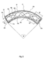
- the receiving coils 40a, 40b have a plurality of measuring fields, in FIG. 2 exemplified by M1, M2.
- the measuring fields each have a winding direction corresponding to the running direction of the windings 43a, 43b.
- the winding directions are indicated by the arrowheads on the windings.
- the exciter coil 20 and the receiver coils 40a, 40b are preferably formed on a printed circuit board by means of printed conductor tracks.
- the carrier body in the case of the printed circuit board, is formed in a circular segment.
- the exciter coil 20 is formed in a circular segment.
- the two receiver coils 40a, 40b (it may also be more) each generate an output voltage Uout1, Uout2 (see. Fig. 1 ), which may have a sinusoidal or cosinusoidal shape.
- the voltages Uout1, Uout2 vary as soon as the angle encoder unit 30 covers one of the measuring fields M1, M2 of the receiving coils 40a, 40b, as in FIG FIG. 5 shown schematically.
- the evaluation unit 4 is connected to the receiving coils 40a, 40b and evaluates the output voltages Uout1, Uout2 of the receiving coils 40a, 40b.
- the output voltages Uout1, Uout2 of the receiving coils 40a, 40b are processed by means of demodulators 10.
- As output voltage a sinusoidal or cosinusoidal voltage curve is usually output.
- the amplitude and frequency of the output voltages are excluded by the at least relative angular position of the angle encoder unit 30 or of the rotating element.
- FIG. 3 an embodiment of the angle encoder unit 30 is shown.
- the angle encoder unit 30 is connected to a rotating element and changes its relative position to the receiving coils 40a, 40b by the movement of the rotating element.
- the angle encoder unit 30 has a carrier body 31, which may be designed, for example, as a printed circuit board.
- the carrier body 31 is annular. In the middle of the support body 31 has a recess 32 through which the rotating element is feasible.
- the oscillating circuits are electromagnetic oscillating circuits LC with a capacitor C and a conductor L as inductive element.
- the resonant circuit LC can be produced by printed on a printed circuit board tracks. It is preferably a passive resonant circuit LC, which has its own natural frequency. The natural frequencies of the resonant circuits may differ from each other.
- the natural frequency of the resonant circuit LC is the frequency of the exciter field or the AC voltage f.
- the oscillating circuits LC are arranged uniformly spaced around the center of the carrier body. In FIG.
- each oscillating circuit in such a way that the natural frequency of the oscillating circuits LC differs from one another.
- each resonant circuit can be uniquely identified by means of the natural frequencies, so that it is possible to clearly determine the position of a resonant circuit relative to the measuring fields.
- the frequency of the alternating voltage U ⁇ is advantageously set alternately, for example, successively in the order of the natural frequencies of the oscillating circuits LC.
- the natural frequency can be set as a function of the differently adjustable AC voltage f.
- the resonant circuits may be designed such that they have the same natural frequency.
- the absolute rotation angle can be detected by a corresponding counting of the voltage periods of the receiving coils.
- FIGS. 4a, 4b a second embodiment is shown. This embodiment differs essentially by the course of the winding of the receiving coil.
- the figures each show only a section of the receiving coils 240a, 240b and are shown in a straight line for a schematic representation. In the actual embodiment, the receiving coils 240a, 240b and the exciting coil 220 extend over a circular segment.
- the windings 243a, 243b of the receiving coils 240a, 240b have a substantially trapezoidal shape.
- the trapezoidal winding 243a, 243b is, as in FIG. 4b represented by a receiving coil 240a, 240b, divided into a plurality of sections 246a, 247b.
- the sections are arranged in different planes E1, E2.
- this feature is shown schematically in the side view.
- the front and back sides of the carrier body 270 form the two planes E1 and E1.
- a portion 246 a of the winding is arranged on one side of the carrier body 270 and the other portion 247 a is arranged on the opposite side of the carrier body 270.
- the connection of the winding sections 246a, 247a takes place through the carrier body 270.
- the winding sections each have connection points 248, which are connected to one another by means of a connection 249 extending through the carrier body.
- each receiving coil is carried out with winding sections which are located in two different planes.
- each receiving coil has approximately the same number of winding sections with a small spacing d1 from the angle encoder unit and the same number of winding sections with a large spacing d2 from the angle encoder unit 30.
- FIG. 12 shows another winding pattern of the receiving coils 340a, 340b according to a third embodiment.
- the windings 343a, 343b are applied to one another with a small phase shift on the carrier body.
- the windings 343a, 343b are substantially immediately adjacent and parallel to each other. The distance can be in the range of a few millimeters, depending on the application.
- the windings 343a, 343b have a trapezoidal basic pattern with the bases of the trapezium angled inwardly toward the legs of the trap.
- the receiving coils 340a, 340b have winding portions 346a, 346b, 347a, 347b arranged in two different planes.
- the mutually parallel winding sections are meanwhile arranged on the same plane. In this way, a crossover execution of the winding is easily implemented.
- the patterns mentioned here from the FIGS. 4a, 4b and 5 have proven in experiments as particularly advantageous embodiments with respect to the signal quality of the output voltage Uout1, Uout2. In addition, it has been found that these patterns are particularly easy to produce.
- the invention also includes other periodic winding patterns that can be imaged within a circle segment.
- the invention is not limited to the aforementioned embodiments.
- the aforementioned embodiments of the excitation coil, receiving coils can be combined as desired with the exemplary embodiments of the angle encoder unit.
- the resonant circuits do not necessarily have to be arranged within a circle segment or quadrangular. It is also conceivable to provide resonant circuits extending along the circumference of the carrier body, similar to the exciter coil. Furthermore, it is also conceivable to provide a resonant circuit extending around the full circle circumference, wherein the resonant circuits are arranged in different radii.
- the starting and end points of the resonant circuits may have, wherein the starting and end points of the resonant circuits are offset from each other, for example, along the circular path angularly offset.
- the rotation angle sensor is also possible to use the rotation angle sensor with a simple circuit arrangement operated at a single AC frequency.
- the evaluation unit 4 is not limited to the above-mentioned embodiment, but can be supplemented by further evaluation electronics.
- the embodiments can be realized in a simple embodiment with an alternating voltage in one frequency.
Abstract
Drehwinkelsensor (2) zum Erfassen der Position eines rotierenden Elements, insbesondere Rotors eines elektrischen Motors, aufweisend: - eine Erregerspule (20), welche mit einer Wechselspannung (Uˆ¼) versorgt wird, um ein zur Wechselspannung (Uˆ¼) korrespondierendes Erregerfeld zu erzeugen, - mindestens zwei Empfangsspulen (40a, 40b, 240a, 240b, 340a, 340b), die mit der Erregerspule (20) derart gekoppelt sind, so dass das Erregerfeld in den Emp-fangsspulen (40a, 40b, 240a, 240b, 340a, 340b) jeweils eine Spannung (Uout1, Uout2) induziert, und - ein Winkelgebereinheit (30), das mit dem rotierenden Element verbindbar ist und mittels dessen die Spannung der Empfangsspulen (40a, 40b, 240a, 240b, 340a, 340b) beeinflussbar ist, dadurch gekennzeichnet, dass die Erregerspule (20) und die Empfangsspulen (40a, 40b, 240a, 240b, 340a, 340b) entlang eines Kreissegment angeordnet sind.Angle of rotation sensor (2) for detecting the position of a rotating element, in particular rotor of an electric motor, comprising: - An excitation coil (20) which is supplied with an AC voltage (U¼) to generate a corresponding to the AC voltage (U¼) exciter field, - At least two receiving coils (40a, 40b, 240a, 240b, 340a, 340b) which are coupled to the excitation coil (20) such that the excitation field in the receiving coils (40a, 40b, 240a, 240b, 340a, 340b ) each induces a voltage (Uout1, Uout2), and an angle encoder unit which can be connected to the rotating element and by means of which the voltage of the receiver coils can be influenced characterized in that the exciter coil (20) and the receiver coils (40a, 40b, 240a, 240b, 340a, 340b) are arranged along a circular segment.
Description
Die Erfindung betrifft einen Drehwinkelsensor zum Erfassen des Drehwinkels eines rotierenden Elements gemäß dem Oberbegriff des Anspruchs 1.The invention relates to a rotation angle sensor for detecting the angle of rotation of a rotating element according to the preamble of claim 1.
Aus der
Davon ausgehend liegt der Erfindung daher die Aufgabe zu Grunde, einen Drehwinkelsensor zum erfassen des Drehwinkel eines rotierenden Elements aufzuzeigen, der möglichst kompakt ausführbar ist.On this basis, the invention is therefore based on the object to show a rotation angle sensor for detecting the rotation angle of a rotating element, which is as compact as possible executable.
Die Aufgabe wird durch die Merkmale des unabhängigen Anspruchs gelöst. Bevorzugte Ausführungsformen sind Gegenstand der abhängigen Ansprüche.The object is solved by the features of the independent claim. Preferred embodiments are subject of the dependent claims.
Der Erfindung liegt der Grundgedanke zu Grunde, den Bauraum durch die Ausführung der Empfangsspulen entlang eines Kreissegments zu verringern. Zum Messen eines Drehwinkels des rotierenden Elements wird daher nicht ein voller Kreisumfang zum Einbau der Empfangsspule benötigt. Stattdessen erstreckt sich die Empfangsspule lediglich sich über einen Teil eines Kreisumfangs bzw. über ein Kreissegment. Damit kann die Empfangsspule sehr kompakt ausgeführt werden und leichter in kleine Bauräume, beispielsweise an einem Motor, integriert werden. Vorteilhaft ist es zwei oder mehr Empfangsspulen zu verwenden. In der nachfolgenden Beschreibung wird daher auf mehrere Empfangsspulen Bezug genommen. Nachfolgende Ausführungsformen können im Prinzip auch mit einer Empfangsspule ausgeführt werden.The invention is based on the basic idea of reducing the installation space through the design of the receiver coils along a circular segment. For measuring a rotation angle of the rotating element, therefore, a full circumference is not required for installation of the receiving coil. Instead, the receiving coil extends only over a part of a circumference or over a circle segment. Thus, the receiving coil can be made very compact and easier in small spaces, such as a motor integrated. It is advantageous to use two or more receiver coils. In the following description, reference will therefore be made to a plurality of receiving coils. Subsequent embodiments can in principle also be carried out with a receiver coil.
Ein weiterer Vorteil der Erfindung liegt darin, dass das Kreissegment mit den Empfangsspulen relativ zum gesamten Kreisumfang variabel positioniert war ist. Es kann an irgendeinem Teilbereich eines Kreisumfangs angeordnet werden. Die Erregerspule, die ist ebenfalls auf einem Kreissegment ausgeführt. Die Einheit aus den Empfangsspulen und der Erregerspule nehmen daher beide nur den Raum auf einem Kreissegment ein.Another advantage of the invention is that the circular segment with the receiving coils was positioned variably relative to the entire circumference. It can be arranged at any part of a circumference. The exciter coil, which is also executed on a circle segment. The unit of the receiving coil and the exciting coil therefore both occupy only the space on a circle segment.
Die Winkelgebereinheit ist mit dem rotierenden Element, beispielsweise eine Welle, verbunden und gibt die Bewegung des rotierenden Elements wieder. Durch das Erfassen der absoluten Position oder der relativen Bewegung des rotierenden Elements zu den Empfangsspulen kann der Drehwinkel des rotierenden Elements mittels der Winkelgebereinheit entweder relativ zu den Empfangsspulen oder absolut in Bezug auf einen Bezugspunkt erfasst werden. Die Winkelgebereinheit ist ein von der Erregerspule und den Empfangsspulen separates Teil, das bspw. parallel benachbart zu den Spulen angeordnet ist.The angle encoder unit is connected to the rotating element, for example a shaft, and reflects the movement of the rotating element. By detecting the absolute position or the relative movement of the rotating element to the receiving coils, the rotational angle of the rotating element can be detected by means of the angle encoder unit either relative to the receiving coils or absolutely with respect to a reference point. The angle encoder unit is one of the exciter coil and the receiving coil separate part, which is, for example, arranged in parallel adjacent to the coils.
Eine vorteilhafte Ausführungsform des erfindungsgemäßen Drehwinkelsensors ist derart ausgebildet, dass sich das Kreissegment im Wesentlichen über einen Winkel von etwa 360°/ (2*n), insbesondere 45°, erstreckt, wobei n eine gerade Zahl ist. Die Ausführungsform ist besonders vorteilhaft zur Verwendung in Kombination mit einem elektrischen Motor, der mehrere Polpaare besitzt. Hier kann statt 2*n die Anzahl der Polpaare eingesetzt werden. Bei einem achtpoligen Motor beispielsweise ist es ausreichend, die Erregerspule und die Empfangsspulen über ein Kreissegment anzuordnen, das sich über 45° erstreckt.An advantageous embodiment of the rotation angle sensor according to the invention is designed such that the circular segment extends substantially over an angle of about 360 ° / (2 * n), in particular 45 °, where n is an even number. The embodiment is particularly advantageous for use in combination with an electric motor having multiple pole pairs. Here, instead of 2 * n, the number of pole pairs can be used. For example, in an eight-pole motor, it is sufficient to arrange the exciting coil and the receiving coils over a circle segment extending over 45 °.
Eine vorteilhafte Ausführungsform des erfindungsgemäßen Drehwinkelsensors ist derart ausgebildet, dass jede Empfangsspule eine Wicklung aufweist, die einen periodischen Verlauf aufweist. Die Wicklungen der Empfangsspulen sind dabei Phasen verschoben zueinander angeordnet.An advantageous embodiment of the rotation angle sensor according to the invention is designed such that each receiving coil has a winding which has a periodic course. The windings of the receiver coils are arranged phase shifted from each other.
Eine vorteilhafte Ausführungsform des erfindungsgemäßen Drehwinkelsensors ist derart ausgebildet, dass die Wicklung mehrere Wicklungsabschnitte aufweist, die jeweils ein von Wicklungsabschnitten eingegrenztes Messfeld definieren. Die Messfelder definieren einzelne in sich im Wesentlichen geschlossene Bereiche. Die Grenzen eines solchen Bereiches werden durch die jeweiligen Wicklungsabschnitte definiert.An advantageous embodiment of the rotation angle sensor according to the invention is designed such that the winding has a plurality of winding sections which each define a measuring field bounded by winding sections. The measuring fields define individual essentially closed areas. The limits of such a range are defined by the respective winding sections.
Eine vorteilhafte Ausführungsform des erfindungsgemäßen Drehwinkelsensors ist derart ausgebildet, dass die Messfelder um einen gemeinsamen Rotationspunkt gleichmäßig beabstandet angeordnet sind.An advantageous embodiment of the rotation angle sensor according to the invention is designed such that the measuring fields are arranged uniformly spaced around a common point of rotation.
Eine vorteilhafte Ausführungsform des erfindungsgemäßen Drehwinkelsensors ist derart ausgebildet, dass die Wicklung einen im Wesentlichen dreiecks- oder trapezförmigen Verlauf aufweist. Mit dieser Form der Empfangsspulen konnte bei Versuchen eine besonders gute Signalgüte der von den Empfangsspulen ausgegebenen Spannungen erreicht werden. Ferner ermöglicht diese Form eine besonders einfache Herstellung der Empfangsspulen.An advantageous embodiment of the rotation angle sensor according to the invention is designed such that the winding has a substantially triangular or trapezoidal shape. With this form of receiving coils, a particularly good signal quality of the voltages output by the receiving coils could be achieved in experiments. Furthermore, this form allows a particularly simple production of the receiving coils.
Eine vorteilhafte Ausführungsform des erfindungsgemäßen Drehwinkelsensors ist derart ausgebildet, dass jede Empfangsspule Wicklungsabschnitte aufweist, die in unterschiedlichen Ebenen angeordnet sind.An advantageous embodiment of the rotation angle sensor according to the invention is designed such that each receiving coil has winding sections which are arranged in different planes.
Es ist besonders vorteilhaft den erfindungsgemäßen Drehwinkelsensors derart weiterzubilden, dass die Wicklungsabschnitte der Empfangsspulen im Wesentlichen gleichmäßig auf zwei Ebenen verteilt angeordnet sind. Die Winkelgebereinheit ist üblicherweise parallel zu den Empfangsspulen angeordnet. Mit dieser Ausführungsform wird erreicht, dass die Wicklungsabschnitte der Empfangsspulen jeweils abwechselnd mit einem größeren und einem kleineren Abstand zu der Winkelgebereinheit angeordnet sind. Die Abstandsverteilung von den Wicklungen der Empfangsspulen zu der Winkelgebereinheit wird dadurch gleichmäßig aufgeteilt. Dadurch wird mit beiden Empfangsspulen eine qualitativ gleichwertige Signalgüte erreicht.It is particularly advantageous to further develop the rotation angle sensor according to the invention such that the winding sections of the receiver coils are distributed substantially uniformly over two planes. The angle encoder unit is usually arranged parallel to the receiver coils. With this embodiment it is achieved that the winding sections of the receiving coils are each arranged alternately with a larger and a smaller distance to the angle encoder unit. The distance distribution from the windings of the receiving coils to the angle encoder unit is thereby divided equally. As a result, a qualitatively equivalent signal quality is achieved with both receiver coils.
Eine vorteilhafte Ausführungsform des erfindungsgemäßen Drehwinkelsensors ist derart ausgebildet, dass die Erregerspule und die Empfangsspulen auf einem Trägerkörper angeordnet sind, der kreissegmentförmig ausgebildet ist. Der Trägerkörper kann beispielsweise als eine Leiterplatine ausgebildet sein.An advantageous embodiment of the rotation angle sensor according to the invention is designed such that the exciter coil and the receiver coils are arranged on a carrier body, which is formed in a circular segment. The carrier body may be formed, for example, as a printed circuit board.
Eine vorteilhafte Ausführungsform des erfindungsgemäßen Drehwinkelsensors ist derart ausgebildet, dass der Trägerkörper ringförmig ausgebildet ist. Diese Ausführungsform ermöglicht insbesondere in Zusammenhang mit einem kreissegmentförmig ausgebildeten Trägerkörper eine besonders kompakte Bauweise der Empfangsspulen und der Erregerspule.An advantageous embodiment of the rotation angle sensor according to the invention is designed such that the carrier body is annular. This embodiment allows a particularly compact design of the receiving coils and the exciter coil, in particular in connection with a carrier segment formed in the shape of a circle segment.
Eine vorteilhafte Ausführungsform des erfindungsgemäßen Drehwinkelsensors ist derart ausgebildet, dass die Winkelgebereinheit einen elektronischen Schwingkreis mit mindestens einem kapazitiven und mindestens einem induktiven Element aufweist.An advantageous embodiment of the rotation angle sensor according to the invention is designed such that the angle encoder unit has an electronic resonant circuit with at least one capacitive and at least one inductive element.
Eine vorteilhafte Ausführungsform des erfindungsgemäßen Drehwinkelsensors ist derart ausgebildet, dass das kapazitive Element ein Kondensator und / oder das induktive Element ein Stromleiter ist. Der Kondensator und das induktive Element können als auf eine Leiterplatine aufgedruckte Leiter oder Leiterbahnen ausgeführt sein. Dies ermöglicht, insbesondere im Zusammenhang mit einem ringförmigen Trägerkörper der Winkelgebereinheit, eine besonders variable Ausnutzung der Anbringfläche auf dem Trägerkörper. Zudem kann die Form der Schwingkreise variabel an den jeweiligen Bedarf angepasst werden.An advantageous embodiment of the rotation angle sensor according to the invention is designed such that the capacitive element is a capacitor and / or the inductive element is a current conductor. The capacitor and the inductive element may be embodied as printed on a printed circuit conductor or conductor tracks. This allows, in particular in connection with an annular carrier body of the angle encoder unit, a particularly variable utilization of the mounting surface on the carrier body. In addition, the shape of the oscillating circuits can be variably adapted to the respective requirements.
Eine vorteilhafte Ausführungsform des erfindungsgemäßen Drehwinkelsensors ist derart ausgebildet, dass die Winkelgebereinheit eine Vielzahl von Schwingkreisen aufweist.An advantageous embodiment of the rotation angle sensor according to the invention is designed such that the angle encoder unit has a plurality of oscillating circuits.
Eine vorteilhafte Ausführungsform des erfindungsgemäßen Drehwinkelsensors ist derart ausgebildet, dass die Anzahl m der Schwingkreise gleich ![]()
ist, wobei alpha der Winkel ist, über den sich das Kreissegment der Erregerspule bzw. Empfangsspulen erstrecken. Die Ausführungsform ist insbesondere dann sinnvoll, wenn die Sensorsignale des Drehwinkelsensors zum Steuern eines elektrischen Motors verwendet werden, bspw. eines bürstenlosen Gleichstrommotors.An advantageous embodiment of the rotation angle sensor according to the invention is designed such that the number m of the resonant circuits equal ![]()
where alpha is the angle through which the circular segment of the exciter coil (s) extend. The embodiment is particularly useful when the sensor signals of the rotation angle sensor are used for controlling an electric motor, for example, a brushless DC motor.
Eine vorteilhafte Ausführungsform des erfindungsgemäßen Drehwinkelsensors ist derart ausgebildet, dass jeder Schwingkreis eine eigene Eigenfrequenz aufweist. Mittels der Eigenfrequenz ist es möglich, jeden Schwingkreis zu identifizieren, sobald es sich innerhalb des Kreissegments der Empfangsspulen befindet. So ist es möglich, den absoluten Drehwinkel des rotierenden Elements bzw. der Winkelgebereinheit zu erfassen. Im einfachsten Fall weisen alle Schwingkreise dieselbe Eigenfrequenz auf.An advantageous embodiment of the rotation angle sensor according to the invention is designed such that each resonant circuit has its own natural frequency. By means of the natural frequency, it is possible to identify each resonant circuit as soon as it is within the circle segment of the receiver coils. It is thus possible to detect the absolute angle of rotation of the rotating element or the angle encoder unit. In the simplest case, all oscillating circuits have the same natural frequency.
Eine vorteilhafte Ausführungsform des erfindungsgemäßen Drehwinkelsensors ist derart ausgebildet, dass die Erregerfrequenz bzw. die Frequenz der Wechselspannung in Abhängigkeit der Eigenfrequenz eines Schwingkreises oder eines der Schwingkreise festgelegt wird. Durch das Einstellen der Erregerfrequenz entsprechend zur Eigenfrequenz eines Schwingkreises oder der Schwingkreise ist es möglich, den Drehwinkel eines speziellen Schwingkreises zu erfassen. Durch abwechselnde Erregerfrequenzen kann der Drehwinkel mehrerer Schwingkreise gezielt erfasst werden. Auf diese Weise können die Empfangsspulen bspw. speziell auf diejenigen Schwingkreise eingestellt werden, die sich innerhalb des Kreissegments der Empfangsspulen befinden.An advantageous embodiment of the rotation angle sensor according to the invention is designed such that the excitation frequency or the frequency of the alternating voltage is determined as a function of the natural frequency of a resonant circuit or one of the resonant circuits. By adjusting the excitation frequency corresponding to the natural frequency of a resonant circuit or the resonant circuits, it is possible to detect the rotation angle of a special resonant circuit. By alternating exciter frequencies, the angle of rotation of several resonant circuits can be specifically detected. In this way, the receiver coils can, for example, be specially adjusted to those resonant circuits that are located within the circular segment of the receiver coils.
Eine vorteilhafte Ausführungsform des erfindungsgemäßen Drehwinkelsensors ist derart ausgebildet, dass die Winkelgebereinheit einen Trägerkörper aufweist und die Schwingkreise gleichmäßig um einen Rotationspunkt herum angeordnet sind.An advantageous embodiment of the rotation angle sensor according to the invention is designed such that the angle encoder unit has a carrier body and the resonant circuits are arranged uniformly around a point of rotation.
Eine vorteilhafte Ausführungsform des erfindungsgemäßen Drehwinkelsensors ist derart ausgebildet, dass der Schwingkreis oder die Schwingkreise innerhalb eines ringförmigen Bereichs des Trägerkörpers angeordnet ist / sind. Auf diese Weise kann die Winkelgebereinheit an unterschiedliche Formen des rotierenden Elements angepasst werden. Insbesondere kann die Winkelgebereinheit auch mit einer Welle mit einem größeren Durchmesser verwendet werden.An advantageous embodiment of the rotation angle sensor according to the invention is designed such that the resonant circuit or the resonant circuits is / are arranged within an annular region of the carrier body. In this way, the angle encoder unit can be adapted to different shapes of the rotating element. In particular, the angle encoder unit can also be used with a shaft with a larger diameter.
Die Erfindung umfasst ferner einen elektrischen Motor, insbesondere einen bürstenlosen Gleichstrommotor, mit einem Drehwinkelsensor nach einem der vorstehenden Ausführungsformen.The invention further comprises an electric motor, in particular a brushless DC motor, with a rotation angle sensor according to one of the preceding embodiments.
Die Erfindung wird nachfolgend anhand eines Ausführungsbeispiels und Figuren näher beschrieben. Es zeigen:
- Fig. 1
- eine schematische Schaltungsanordnung mit einem ersten Ausführungsbeispiel des erfindungsgemäßen Drehwinkelsensors,
- Fig. 2
- eine schematische Darstellung der Erregerspule und der Empfangsspulen gemäß dem ersten Ausführungsbeispiels,
- Fig. 3
- eine schematische Darstellung der Winkelgebereinheit gemäß dem ersten Ausführungsbeispiel,
- Fig. 4a
- eine schematische Darstellung eines Ausschnitts der Erregerspule und der Empfangsspulen gemäß einem zweiten Ausführungsbeispiel,
- Fig. 4b
- eine vergrößerte Darstellung einer einzelnen Wicklung einer Empfangsspule aus
Figur 4a , - Fig. 5
- eine schematische seitliche Teilansicht der Empfangsspule neben einer Winkelgebereinheit, und
- Fig. 6
- eine alternative Wicklungsform der Empfangsspulen gemäß einem dritten Ausführungsbeispiel.
- Fig. 1
- a schematic circuit arrangement with a first embodiment of the rotation angle sensor according to the invention,
- Fig. 2
- a schematic representation of the excitation coil and the receiving coil according to the first embodiment,
- Fig. 3
- a schematic representation of the angle encoder unit according to the first embodiment,
- Fig. 4a
- a schematic representation of a section of the excitation coil and the receiving coil according to a second embodiment,
- Fig. 4b
- an enlarged view of a single winding of a receiving coil
FIG. 4a . - Fig. 5
- a schematic partial side view of the receiving coil in addition to an angle encoder unit, and
- Fig. 6
- an alternative winding form of the receiving coil according to a third embodiment.
Die Spannungsquelle 3 ist mit der Erregerspule 20 elektrisch verbunden und versorgt diese mit einer Wechselspannung U∼ zum erzeugen eines zur Wechselspannung U∼ korrespondierenden Erregerfeldes. Die Wechselspannung U∼ weist eine Spannungsfrequenz auf f, die variabel einstellbar ist und in unterschiedliche Spannungsfrequenzen bzw. Frequenzen einstellbar ist. Die Wechselspannung kann beispielsweise abwechselnd in unterschiedliche Frequenzen eingestellt werden. Dies kann derart erfolgen, dass die Spannungsfrequenz f mittels Addition mehrerer Spannungsfrequenzen f1, f2 eingestellt wird. Hierzu weist die Spannungsquelle 3 zunächst zwei Wechselspannungserzeuger 5a und 5b auf, die jeweils eine Wechselspannung in unterschiedlichen Frequenzen f1, f2 erzeugen. Diese Ausgestaltung hat den Vorteil, dass die Wechselspannung U∼ leicht durch Variierung der Summenteile veränderbar ist. Die Ausgangssignale der Spannungserzeuger 5a und 5b werden einem Addierer 6 zugeführt. Die Summe der Ausgangssignale werden einer Treibereinheit 7 zugeführt, der aus diesem Signal die Wechselspannung U∼ erzeugt und diese der Erregerspule 20 zuführt. Es ist jedoch auch denkbar andere bereits bekannte Lösungen zur Erzeugung einer Wechselspannung in unterschiedlichen Frequenzen zu verwenden.The
Der Drehwinkelsensor 2 umfasst im Wesentlichen die Erregerspule 20, eine Winkelgebereinheit 30 und zwei Empfangsspulen 40a, 40b. In
Die Erregerspule 20 ist vorzugsweise als eine auf einer Leiterplatine aufgedruckte Leiterbahn ausgebildet und um die Empfangsspulen 40a, 40b herum angeordnet, so dass das durch die Wechselspannung erzeugte Erregerfeld eine Spannung in den Empfangsspulen 40a, 40b induziert. Die Erregerspule 20 weist eine Wicklung 21 auf, die einen sich über einen Kreissegment erstreckt. In diesem Ausführungsbeispiel umfasst das Kreissegment im Wesentlichen einen Winkel von alpha=90°. Leichte Abweichungen sind möglich. Die Wicklung 21 ist über zwei Bahnen gewickelt, wobei die Anschlusspunkte 22 außen angeordnet sind. Die Erregerspule 20 ist über die Anschlusspunkte 22 mit der Spannungsquelle 3 verbunden. In radialer Errichtung weist die Erregerspule 20 jeweils eine geradlinige Begrenzung 25a, 25b auf, die mit zwei kreisbogenförmigen Abschnitten 26a, 26b einen Bereich eingrenzen, in der die Empfangsspulen 40a, 40b angeordnet sind. Auf diese Weise wird sichergestellt, dass die Empfangsspulen 40a, 40b mit der Erregerspule 20 induktiv gekoppelt sind.The
Die Empfangsspulen 40a, 40b weisen jeweils eine Wicklung 43a, 43b auf. Die Wicklungen 43a, 43b haben einen sinus- bzw. kosinusförmigen Verlauf. Denkbar sind auch andere periodische Formen, wie in den anderen Ausführungsbeispielen gezeigt. Die Wicklungen 43a, 43b haben einen Anfangspunkt 41a, 41b, die an einem Ende des Kreissegments angeordnet sind. Die Wicklungen 43a, 43b laufen von dort entsprechend ihrer periodischer Form entlang des Kreissegments bis zum anderen Ende des Kreissegments. Es ist vorteilhaft die Wicklungen 43a, 43b der Empfangsspulen 40a, 40b mit einem Abstand von dem Endabschnitt der Erregerspule 20 zu versehen, da ansonsten die Messgenauigkeit in diesem Bereich beeinträchtigt werden kann. Es hat sich als vorteilhaft herausgestellt einen Abstand einzuhalten, der in etwa dem Radius der Erregerspule entspricht. Von dem anderen Ende laufen die Wicklungen 43a, 43b wie eine reflektierte Welle zum ersten Ende des Kreissegments zurück. Vorzugsweise ist die Periodenlänge der Wicklungen derart ausgeführt, dass ein ganzzahliges Vielfaches der Periode innerhalb des Kreissegments hineinpasst, wie im Falle der Empfangsspule 40a. Andernfalls wird das, wie im Falle der Empfangsspule 40b, die Wicklung 43b über einen im Wesentlichen Abschnitt im Wesentlichen entlang der Wicklung der Erregerspule 20 nach innen geführt. Von dort aus verläuft die Wicklung 43b nach der vorgegebenen periodischen Form. Das Ende der Wicklung 43a, 43b bildet jeweils ein Endpunkt 42a, 42b. Über die Anfangs- und Endpunkte 41a, 42a, 41b, 42b wird die Ausgasspannung Uout1∼, Uout2∼ von den Empfangsspulen abgegriffen.The receiving
Die Empfangsspulen 40a, 40b weisen mehrere Messfelder auf, in
Die Erregerspule 20 und die Empfangsspulen 40a, 40b sind vorzugsweise auf einer Leiterplatine mittels aufgedruckten Leiterbahnen ausgebildet. Der Trägerkörper, in dem Fall die Leiterplatine, ist kreissegmentförmig ausgebildet. Vorteilhafterweise nicht wesentlich größer, das der Bereich, den die Erregerspule 20 einnimmt.The
Aufgrund der induktiven Kopplung mit der Erregerspule 20 erzeugen die zwei Empfangsspulen 40a, 40b (es können auch mehr sein) jeweils eine Ausgangsspannung Uout1, Uout2 (vgl.
Die Auswerteeinheit 4 ist mit den Empfangsspulen 40a, 40b verbunden und wertet die Ausgangsspannungen Uout1, Uout2 der Empfangsspulen 40a, 40b aus. Die Ausgangsspannungen Uout1, Uout2 der Empfangsspulen 40a, 40b werden mittels Demodulatoren 10 verarbeitet. Als Ausgangsspannung wird in der Regel ein sinusoder kosinusförmiger Spannungsverlauf ausgegeben. Die Amplitude und Frequenz der Ausgangsspannungen gibt Ausschluss über die zumindest relative Winkelposition der Winkelgebereinheit 30 bzw. des rotierenden Elements.The evaluation unit 4 is connected to the receiving
In
Die Winkelgebereinheit 30 weist einen Trägerkörper 31 auf, der beispielsweise als eine Leiterplatine ausgeführt sein kann. Der Trägerkörper 31 ist ringförmig ausgebildet. In der Mitte weist der Trägerkörper 31 eine Ausnehmung 32 auf, durch die das rotierende Element durchführbar ist.The
Auf einer Fläche des Trägerkörpers 31 sind mehrere Schwingkreise LC innerhalb des ringförmigen Bereichs angeordnet. Bei den Schwingkreisen handelt es sich um elektromagnetische Schwingkreise LC mit einem Kondensator C und einem Stromleiter L als induktives Element. Der Schwingkreis LC kann mittels auf einer Leiterplatine aufgedruckten Leiterbahnen hergestellt werden. Es handelt sich vorzugsweise um einen passiven Schwingkreis LC, der eine eigene Eigenfrequenz aufweist. Die Eigenfrequenzen der Schwingkreise können sich voneinander unterscheiden. Vorzugsweise beträgt die Eigenfrequenz des Schwingkreis LC der Frequenz des Erregerfeldes bzw. der Wechselspannungsfrequenz f. Vorzugsweise sind die Schwingkreise LC um den Mittelpunkt des Trägerkörper herum gleichmäßig beabstandet angeordnet. In ![]()
ist, wobei alpha der Winkel ist, über den sich das Kreissegment der Erregerspule bzw. Empfangsspulen erstreckt.On one surface of the ![]()
where alpha is the angle through which the circular segment of the excitation coil (s) extends.
Besonders vorteilhaft ist es, jeden Schwingkreis derart auszulegen, dass sich die Eigenfrequenz der Schwingkreise LC voneinander unterscheiden. Auf diese Weise ist mittels der Eigenfrequenzen jeder Schwingkreis eindeutig identifizierbar, so dass es möglich ist, die Position eines Schwingkreises relativ zu den Messfeldern eindeutig festzustellen. Vorteilhafterweise wird hierzu die Frequenz der Wechselspannung U∼ abwechselnd, bspw. nacheinander in der Reihenfolge der Eigenfrequenzen der Schwingkreise LC eingestellt. Alternativ kann die Eigenfrequenz in Abhängigkeit der unterschiedlich einstellbaren Wechselspannungsfrequenzen f festgelegt werden.It is particularly advantageous to design each oscillating circuit in such a way that the natural frequency of the oscillating circuits LC differs from one another. In this way, each resonant circuit can be uniquely identified by means of the natural frequencies, so that it is possible to clearly determine the position of a resonant circuit relative to the measuring fields. For this purpose, the frequency of the alternating voltage U~ is advantageously set alternately, for example, successively in the order of the natural frequencies of the oscillating circuits LC. Alternatively, the natural frequency can be set as a function of the differently adjustable AC voltage f.
Alternativ dazu können die Schwingkreise derart ausgelegt sein, dass sie dieselbe Eigenfrequenz aufweisen. In solch einem Fall kann der absolute Drehwinkel durch ein entsprechendes Zählen der Spannungsperioden der Empfangsspulen erfasst werden.Alternatively, the resonant circuits may be designed such that they have the same natural frequency. In such a case, the absolute rotation angle can be detected by a corresponding counting of the voltage periods of the receiving coils.
In den
Die Wicklungen 243a, 243b der Empfangsspulen 240a, 240b weisen eine im wesentlichen trapezförmige Form auf. Die trapezförmige Wicklung 243a, 243b ist, wie in
Ein Abschnitt 246a der Wicklung ist auf einer Seite des Trägerkörpers 270 angeordnet und der andere Abschnitt 247a ist auf der gegenüberliegenden Seite des Trägerkörpers 270 angeordnet. Die Verbindung der Wicklungsabschnitte 246a, 247a erfolgt durch den Trägerkörper 270 hindurch. Hierzu weisen die Wicklungsabschnitte jeweils Anschlusspunkte 248 auf, die mittels einer durch die Trägerkörper verlaufende Verbindung 249 miteinander verbunden sind.A
In den
In
Die hier genannten Muster aus den
Die Erfindung ist nicht auf die vorgenannten Ausführungsbeispiele beschränkt. Die vorgenannten Ausführungsbeispiele der Erregerspule, Empfangsspulen sind mit den Ausführungsbeispielen der Winkelgebereinheit beliebig kombinierbar.The invention is not limited to the aforementioned embodiments. The aforementioned embodiments of the excitation coil, receiving coils can be combined as desired with the exemplary embodiments of the angle encoder unit.
Die Schwingkreise müssen nicht zwangsläufig innerhalb eines Kreissegments angeordnet oder viereckig ausgebildet sein. Es ist auch denkbar sich entlang des Umfangs des Trägerkörpers verlaufende Schwingkreise, ähnlich zu der Erregerspule, vorzusehen. Ferner ist es auch denkbar eine um den vollen Kreisumfang verlaufenden Schwingkreis vorzusehen, wobei die Schwingkreise in unterschiedlichen Radien angeordnet sind. Die Anfangs- und Endpunkte der Schwingkreise können dabei aufweisen, wobei die Anfangs- und Endpunkte der Schwingkreise versetzt voneinander angeordnet sein, beispielsweise entlang der Kreisbahn winkelversetzt.The resonant circuits do not necessarily have to be arranged within a circle segment or quadrangular. It is also conceivable to provide resonant circuits extending along the circumference of the carrier body, similar to the exciter coil. Furthermore, it is also conceivable to provide a resonant circuit extending around the full circle circumference, wherein the resonant circuits are arranged in different radii. The starting and end points of the resonant circuits may have, wherein the starting and end points of the resonant circuits are offset from each other, for example, along the circular path angularly offset.
Es ist ferner möglich, den Drehwinkelsensor mit einer einfachen Schaltungsanordnung zu verwenden, die mit einer einzigen Wechselspannungsfrequenz betrieben wird. Des Weiteren ist die Auswerteeinheit 4 nicht auf das oben genannte Ausführungsbeispiel beschränkt, sondern kann durch weitere Auswerteelektronik ergänzt werden. Ferner können die Ausführungsbeispiele in einer einfachen Ausführung auch mit einer Wechselspannung in einer Frequenz realisiert werden.It is also possible to use the rotation angle sensor with a simple circuit arrangement operated at a single AC frequency. Furthermore, the evaluation unit 4 is not limited to the above-mentioned embodiment, but can be supplemented by further evaluation electronics. Furthermore, the embodiments can be realized in a simple embodiment with an alternating voltage in one frequency.
Claims (15)
dadurch gekennzeichnet, dass die Erregerspule (20) und die Empfangsspule (40a, 40b, 240a, 240b, 340a, 340b) entlang eines Kreissegment angeordnet sind.
characterized in that the exciter coil (20) and the receiver coil (40a, 40b, 240a, 240b, 340a, 340b) are arranged along a circular segment.
ist, wobei alpha der Winkel ist, über den sich das Kreissegment der Erregerspule (20) bzw. Empfangsspulen (40a, 40b, 240a, 240b, 340a, 340b) erstreckt.Angle of rotation sensor (2) according to one of the preceding claims, characterized in that the number m of the oscillating circuits (LC) is the same
where alpha is the angle through which the circular segment of the exciter coil (20) or receiver coils (40a, 40b, 240a, 240b, 340a, 340b) extends.
Applications Claiming Priority (1)
| Application Number | Priority Date | Filing Date | Title |
|---|---|---|---|
| DE102013225918.2A DE102013225918A1 (en) | 2013-12-13 | 2013-12-13 | Inductive rotation angle sensor with a circular segment-shaped exciter and receiver coil |
Publications (1)
| Publication Number | Publication Date |
|---|---|
| EP2884238A1 true EP2884238A1 (en) | 2015-06-17 |
Family
ID=52101146
Family Applications (1)
| Application Number | Title | Priority Date | Filing Date |
|---|---|---|---|
| EP14197736.3A Ceased EP2884238A1 (en) | 2013-12-13 | 2014-12-12 | Inductive rotation angle sensor with a circular segment shaped excitation and receiver coil |
Country Status (2)
| Country | Link |
|---|---|
| EP (1) | EP2884238A1 (en) |
| DE (1) | DE102013225918A1 (en) |
Cited By (4)
| Publication number | Priority date | Publication date | Assignee | Title |
|---|---|---|---|---|
| CN107747956A (en) * | 2017-08-30 | 2018-03-02 | 中国科学院上海技术物理研究所 | A kind of data fusion method of round induction synchrometer |
| CN111337569A (en) * | 2020-04-16 | 2020-06-26 | 中国科学院海洋研究所 | Novel pulse near-field and far-field combined eddy current sensor |
| EP3792600A1 (en) * | 2019-09-12 | 2021-03-17 | TE Connectivity Belgium BVBA | Sensor device for measuring the rotational position of an element |
| EP4151954A1 (en) * | 2021-09-17 | 2023-03-22 | Scania CV AB | Sensor arrangement for determining an angular position of a shaft in a vehicle |
Families Citing this family (1)
| Publication number | Priority date | Publication date | Assignee | Title |
|---|---|---|---|---|
| DE102014212971A1 (en) | 2014-07-03 | 2016-01-07 | Continental Teves Ag & Co. Ohg | Angle encoder unit for an inductive angle sensor with a reference resonant circuit |
Citations (4)
| Publication number | Priority date | Publication date | Assignee | Title |
|---|---|---|---|---|
| EP0182085A2 (en) * | 1984-10-19 | 1986-05-28 | Kollmorgen Corporation | Position and speed sensors |
| WO2005098370A1 (en) * | 2004-04-09 | 2005-10-20 | Ksr International Co. | Inductive position sensor |
| US20050270040A1 (en) * | 2004-02-17 | 2005-12-08 | Stridsberg Innovation Ab | Redundant compact encoders |
| EP1828722B1 (en) | 2004-12-20 | 2011-11-02 | Howard, Mark Anthony | Inductive position sensor |
Family Cites Families (4)
| Publication number | Priority date | Publication date | Assignee | Title |
|---|---|---|---|---|
| US7538544B2 (en) * | 2004-04-09 | 2009-05-26 | Ksr Technologies Co. | Inductive position sensor |
| US7449878B2 (en) * | 2005-06-27 | 2008-11-11 | Ksr Technologies Co. | Linear and rotational inductive position sensor |
| DE102008000630A1 (en) * | 2008-03-12 | 2009-09-17 | Robert Bosch Gmbh | Method and device for monitoring and checking a measuring device |
| DE102011004348A1 (en) * | 2011-02-17 | 2012-08-23 | Beckhoff Automation Gmbh | Method and position detection device for detecting a position of a movable element of a drive device |
-
2013
- 2013-12-13 DE DE102013225918.2A patent/DE102013225918A1/en not_active Withdrawn
-
2014
- 2014-12-12 EP EP14197736.3A patent/EP2884238A1/en not_active Ceased
Patent Citations (4)
| Publication number | Priority date | Publication date | Assignee | Title |
|---|---|---|---|---|
| EP0182085A2 (en) * | 1984-10-19 | 1986-05-28 | Kollmorgen Corporation | Position and speed sensors |
| US20050270040A1 (en) * | 2004-02-17 | 2005-12-08 | Stridsberg Innovation Ab | Redundant compact encoders |
| WO2005098370A1 (en) * | 2004-04-09 | 2005-10-20 | Ksr International Co. | Inductive position sensor |
| EP1828722B1 (en) | 2004-12-20 | 2011-11-02 | Howard, Mark Anthony | Inductive position sensor |
Cited By (6)
| Publication number | Priority date | Publication date | Assignee | Title |
|---|---|---|---|---|
| CN107747956A (en) * | 2017-08-30 | 2018-03-02 | 中国科学院上海技术物理研究所 | A kind of data fusion method of round induction synchrometer |
| EP3792600A1 (en) * | 2019-09-12 | 2021-03-17 | TE Connectivity Belgium BVBA | Sensor device for measuring the rotational position of an element |
| US11441885B2 (en) | 2019-09-12 | 2022-09-13 | Te Connectivity Germany Gmbh | Sensor device for measuring the rotational position of an element |
| CN111337569A (en) * | 2020-04-16 | 2020-06-26 | 中国科学院海洋研究所 | Novel pulse near-field and far-field combined eddy current sensor |
| EP4151954A1 (en) * | 2021-09-17 | 2023-03-22 | Scania CV AB | Sensor arrangement for determining an angular position of a shaft in a vehicle |
| WO2023043355A1 (en) * | 2021-09-17 | 2023-03-23 | Scania Cv Ab | Sensor arrangement for determining an angular position of a shaft in a vehicle |
Also Published As
| Publication number | Publication date |
|---|---|
| DE102013225918A1 (en) | 2015-06-18 |
Similar Documents
| Publication | Publication Date | Title |
|---|---|---|
| EP2884236A1 (en) | Inductive rotational angle and torque sensor with a position sender unit comprising resonant circuits | |
| DE102006026543B4 (en) | Position encoder and associated method for detecting a position of a rotor of a machine | |
| DE102017210655B4 (en) | Rotation angle sensor | |
| EP2884238A1 (en) | Inductive rotation angle sensor with a circular segment shaped excitation and receiver coil | |
| EP3365634B1 (en) | Rotation angle sensor | |
| EP0334854B1 (en) | Measurement system for rotation angle and/or rotation speed | |
| EP0909955A2 (en) | Inductive angular sensor | |
| DE102015220615A1 (en) | Rotation angle sensor | |
| DE102013218768A1 (en) | Inductive position measuring device | |
| DE102017222063A1 (en) | Inductive position measuring device | |
| EP3555571B1 (en) | Sensor system for determining at least one rotation property of an element rotating about at least one rotational axis | |
| DE102015220617A1 (en) | Rotation angle sensor | |
| DE112021003215T5 (en) | Torque sensing device and method | |
| EP2834601B1 (en) | Method and arrangement for determining the position of a component | |
| EP2884237A1 (en) | Inductive rotation angle sensor | |
| WO2016045816A1 (en) | Sensor arrangement for path and/or angle measurement | |
| EP2884234A1 (en) | Inductive sensor with a measured displacement of any length | |
| DE102004026311B4 (en) | locator | |
| DE202006008962U1 (en) | Position generator for detecting the position of the rotor of an engine based on a change in the inductance of an inductive component dependent on movement | |
| DE102016204016A1 (en) | Tilt-tolerant displacement sensor | |
| DE102022208112A1 (en) | INDUCTIVE ANGLE MEASUREMENT DEVICE | |
| EP3904836B1 (en) | Inductive position measurement device | |
| EP2884235A1 (en) | Inductive sensor based on the nonius principle | |
| DE102016224854A1 (en) | Sensor system for determining at least one rotational property of an element rotating about at least one axis of rotation | |
| EP3975211B1 (en) | Unification of resolver and inductive rotor supply in one magnetic circuit |
Legal Events
| Date | Code | Title | Description |
|---|---|---|---|
| PUAI | Public reference made under article 153(3) epc to a published international application that has entered the european phase |
Free format text: ORIGINAL CODE: 0009012 |
|
| 17P | Request for examination filed |
Effective date: 20141212 |
|
| AK | Designated contracting states |
Kind code of ref document: A1 Designated state(s): AL AT BE BG CH CY CZ DE DK EE ES FI FR GB GR HR HU IE IS IT LI LT LU LV MC MK MT NL NO PL PT RO RS SE SI SK SM TR |
|
| AX | Request for extension of the european patent |
Extension state: BA ME |
|
| R17P | Request for examination filed (corrected) |
Effective date: 20151217 |
|
| RBV | Designated contracting states (corrected) |
Designated state(s): AL AT BE BG CH CY CZ DE DK EE ES FI FR GB GR HR HU IE IS IT LI LT LU LV MC MK MT NL NO PL PT RO RS SE SI SK SM TR |
|
| 17Q | First examination report despatched |
Effective date: 20180522 |
|
| RAP1 | Party data changed (applicant data changed or rights of an application transferred) |
Owner name: CONTINENTAL TEVES AG & CO. OHG |
|
| STAA | Information on the status of an ep patent application or granted ep patent |
Free format text: STATUS: THE APPLICATION HAS BEEN REFUSED |
|
| 18R | Application refused |
Effective date: 20190809 |