EP2884208B1 - Vacuum insulation panel and refrigerator including a vacuum insulation panel - Google Patents
Vacuum insulation panel and refrigerator including a vacuum insulation panel Download PDFInfo
- Publication number
- EP2884208B1 EP2884208B1 EP14188779.4A EP14188779A EP2884208B1 EP 2884208 B1 EP2884208 B1 EP 2884208B1 EP 14188779 A EP14188779 A EP 14188779A EP 2884208 B1 EP2884208 B1 EP 2884208B1
- Authority
- EP
- European Patent Office
- Prior art keywords
- layer
- sheathing material
- getter
- insulation panel
- vacuum insulation
- Prior art date
- Legal status (The legal status is an assumption and is not a legal conclusion. Google has not performed a legal analysis and makes no representation as to the accuracy of the status listed.)
- Active
Links
Images







Classifications
-
- F—MECHANICAL ENGINEERING; LIGHTING; HEATING; WEAPONS; BLASTING
- F25—REFRIGERATION OR COOLING; COMBINED HEATING AND REFRIGERATION SYSTEMS; HEAT PUMP SYSTEMS; MANUFACTURE OR STORAGE OF ICE; LIQUEFACTION SOLIDIFICATION OF GASES
- F25D—REFRIGERATORS; COLD ROOMS; ICE-BOXES; COOLING OR FREEZING APPARATUS NOT OTHERWISE PROVIDED FOR
- F25D23/00—General constructional features
- F25D23/06—Walls
- F25D23/065—Details
-
- B—PERFORMING OPERATIONS; TRANSPORTING
- B32—LAYERED PRODUCTS
- B32B—LAYERED PRODUCTS, i.e. PRODUCTS BUILT-UP OF STRATA OF FLAT OR NON-FLAT, e.g. CELLULAR OR HONEYCOMB, FORM
- B32B5/00—Layered products characterised by the non- homogeneity or physical structure, i.e. comprising a fibrous, filamentary, particulate or foam layer; Layered products characterised by having a layer differing constitutionally or physically in different parts
- B32B5/02—Layered products characterised by the non- homogeneity or physical structure, i.e. comprising a fibrous, filamentary, particulate or foam layer; Layered products characterised by having a layer differing constitutionally or physically in different parts characterised by structural features of a fibrous or filamentary layer
-
- B—PERFORMING OPERATIONS; TRANSPORTING
- B32—LAYERED PRODUCTS
- B32B—LAYERED PRODUCTS, i.e. PRODUCTS BUILT-UP OF STRATA OF FLAT OR NON-FLAT, e.g. CELLULAR OR HONEYCOMB, FORM
- B32B15/00—Layered products comprising a layer of metal
- B32B15/04—Layered products comprising a layer of metal comprising metal as the main or only constituent of a layer, which is next to another layer of the same or of a different material
- B32B15/043—Layered products comprising a layer of metal comprising metal as the main or only constituent of a layer, which is next to another layer of the same or of a different material of metal
-
- B—PERFORMING OPERATIONS; TRANSPORTING
- B32—LAYERED PRODUCTS
- B32B—LAYERED PRODUCTS, i.e. PRODUCTS BUILT-UP OF STRATA OF FLAT OR NON-FLAT, e.g. CELLULAR OR HONEYCOMB, FORM
- B32B15/00—Layered products comprising a layer of metal
- B32B15/14—Layered products comprising a layer of metal next to a fibrous or filamentary layer
-
- B—PERFORMING OPERATIONS; TRANSPORTING
- B32—LAYERED PRODUCTS
- B32B—LAYERED PRODUCTS, i.e. PRODUCTS BUILT-UP OF STRATA OF FLAT OR NON-FLAT, e.g. CELLULAR OR HONEYCOMB, FORM
- B32B15/00—Layered products comprising a layer of metal
- B32B15/20—Layered products comprising a layer of metal comprising aluminium or copper
-
- B—PERFORMING OPERATIONS; TRANSPORTING
- B32—LAYERED PRODUCTS
- B32B—LAYERED PRODUCTS, i.e. PRODUCTS BUILT-UP OF STRATA OF FLAT OR NON-FLAT, e.g. CELLULAR OR HONEYCOMB, FORM
- B32B17/00—Layered products essentially comprising sheet glass, or glass, slag, or like fibres
- B32B17/06—Layered products essentially comprising sheet glass, or glass, slag, or like fibres comprising glass as the main or only constituent of a layer, next to another layer of a specific material
- B32B17/061—Layered products essentially comprising sheet glass, or glass, slag, or like fibres comprising glass as the main or only constituent of a layer, next to another layer of a specific material of metal
-
- F—MECHANICAL ENGINEERING; LIGHTING; HEATING; WEAPONS; BLASTING
- F16—ENGINEERING ELEMENTS AND UNITS; GENERAL MEASURES FOR PRODUCING AND MAINTAINING EFFECTIVE FUNCTIONING OF MACHINES OR INSTALLATIONS; THERMAL INSULATION IN GENERAL
- F16L—PIPES; JOINTS OR FITTINGS FOR PIPES; SUPPORTS FOR PIPES, CABLES OR PROTECTIVE TUBING; MEANS FOR THERMAL INSULATION IN GENERAL
- F16L59/00—Thermal insulation in general
- F16L59/06—Arrangements using an air layer or vacuum
- F16L59/065—Arrangements using an air layer or vacuum using vacuum
-
- F—MECHANICAL ENGINEERING; LIGHTING; HEATING; WEAPONS; BLASTING
- F25—REFRIGERATION OR COOLING; COMBINED HEATING AND REFRIGERATION SYSTEMS; HEAT PUMP SYSTEMS; MANUFACTURE OR STORAGE OF ICE; LIQUEFACTION SOLIDIFICATION OF GASES
- F25D—REFRIGERATORS; COLD ROOMS; ICE-BOXES; COOLING OR FREEZING APPARATUS NOT OTHERWISE PROVIDED FOR
- F25D23/00—General constructional features
- F25D23/06—Walls
-
- B—PERFORMING OPERATIONS; TRANSPORTING
- B32—LAYERED PRODUCTS
- B32B—LAYERED PRODUCTS, i.e. PRODUCTS BUILT-UP OF STRATA OF FLAT OR NON-FLAT, e.g. CELLULAR OR HONEYCOMB, FORM
- B32B2250/00—Layers arrangement
- B32B2250/03—3 layers
-
- B—PERFORMING OPERATIONS; TRANSPORTING
- B32—LAYERED PRODUCTS
- B32B—LAYERED PRODUCTS, i.e. PRODUCTS BUILT-UP OF STRATA OF FLAT OR NON-FLAT, e.g. CELLULAR OR HONEYCOMB, FORM
- B32B2262/00—Composition or structural features of fibres which form a fibrous or filamentary layer or are present as additives
- B32B2262/10—Inorganic fibres
- B32B2262/101—Glass fibres
-
- B—PERFORMING OPERATIONS; TRANSPORTING
- B32—LAYERED PRODUCTS
- B32B—LAYERED PRODUCTS, i.e. PRODUCTS BUILT-UP OF STRATA OF FLAT OR NON-FLAT, e.g. CELLULAR OR HONEYCOMB, FORM
- B32B2307/00—Properties of the layers or laminate
- B32B2307/30—Properties of the layers or laminate having particular thermal properties
- B32B2307/304—Insulating
-
- B—PERFORMING OPERATIONS; TRANSPORTING
- B32—LAYERED PRODUCTS
- B32B—LAYERED PRODUCTS, i.e. PRODUCTS BUILT-UP OF STRATA OF FLAT OR NON-FLAT, e.g. CELLULAR OR HONEYCOMB, FORM
- B32B2307/00—Properties of the layers or laminate
- B32B2307/70—Other properties
- B32B2307/724—Permeability to gases, adsorption
-
- B—PERFORMING OPERATIONS; TRANSPORTING
- B32—LAYERED PRODUCTS
- B32B—LAYERED PRODUCTS, i.e. PRODUCTS BUILT-UP OF STRATA OF FLAT OR NON-FLAT, e.g. CELLULAR OR HONEYCOMB, FORM
- B32B2311/00—Metals, their alloys or their compounds
- B32B2311/24—Aluminium
-
- B—PERFORMING OPERATIONS; TRANSPORTING
- B32—LAYERED PRODUCTS
- B32B—LAYERED PRODUCTS, i.e. PRODUCTS BUILT-UP OF STRATA OF FLAT OR NON-FLAT, e.g. CELLULAR OR HONEYCOMB, FORM
- B32B2457/00—Electrical equipment
-
- B—PERFORMING OPERATIONS; TRANSPORTING
- B32—LAYERED PRODUCTS
- B32B—LAYERED PRODUCTS, i.e. PRODUCTS BUILT-UP OF STRATA OF FLAT OR NON-FLAT, e.g. CELLULAR OR HONEYCOMB, FORM
- B32B2509/00—Household appliances
- B32B2509/10—Refrigerators or refrigerating equipment
-
- F—MECHANICAL ENGINEERING; LIGHTING; HEATING; WEAPONS; BLASTING
- F25—REFRIGERATION OR COOLING; COMBINED HEATING AND REFRIGERATION SYSTEMS; HEAT PUMP SYSTEMS; MANUFACTURE OR STORAGE OF ICE; LIQUEFACTION SOLIDIFICATION OF GASES
- F25D—REFRIGERATORS; COLD ROOMS; ICE-BOXES; COOLING OR FREEZING APPARATUS NOT OTHERWISE PROVIDED FOR
- F25D2201/00—Insulation
- F25D2201/10—Insulation with respect to heat
- F25D2201/14—Insulation with respect to heat using subatmospheric pressure
-
- Y—GENERAL TAGGING OF NEW TECHNOLOGICAL DEVELOPMENTS; GENERAL TAGGING OF CROSS-SECTIONAL TECHNOLOGIES SPANNING OVER SEVERAL SECTIONS OF THE IPC; TECHNICAL SUBJECTS COVERED BY FORMER USPC CROSS-REFERENCE ART COLLECTIONS [XRACs] AND DIGESTS
- Y10—TECHNICAL SUBJECTS COVERED BY FORMER USPC
- Y10T—TECHNICAL SUBJECTS COVERED BY FORMER US CLASSIFICATION
- Y10T428/00—Stock material or miscellaneous articles
- Y10T428/12—All metal or with adjacent metals
- Y10T428/12493—Composite; i.e., plural, adjacent, spatially distinct metal components [e.g., layers, joint, etc.]
- Y10T428/12535—Composite; i.e., plural, adjacent, spatially distinct metal components [e.g., layers, joint, etc.] with additional, spatially distinct nonmetal component
- Y10T428/12597—Noncrystalline silica or noncrystalline plural-oxide component [e.g., glass, etc.]
-
- Y—GENERAL TAGGING OF NEW TECHNOLOGICAL DEVELOPMENTS; GENERAL TAGGING OF CROSS-SECTIONAL TECHNOLOGIES SPANNING OVER SEVERAL SECTIONS OF THE IPC; TECHNICAL SUBJECTS COVERED BY FORMER USPC CROSS-REFERENCE ART COLLECTIONS [XRACs] AND DIGESTS
- Y10—TECHNICAL SUBJECTS COVERED BY FORMER USPC
- Y10T—TECHNICAL SUBJECTS COVERED BY FORMER US CLASSIFICATION
- Y10T428/00—Stock material or miscellaneous articles
- Y10T428/12—All metal or with adjacent metals
- Y10T428/12493—Composite; i.e., plural, adjacent, spatially distinct metal components [e.g., layers, joint, etc.]
- Y10T428/12535—Composite; i.e., plural, adjacent, spatially distinct metal components [e.g., layers, joint, etc.] with additional, spatially distinct nonmetal component
- Y10T428/12611—Oxide-containing component
-
- Y—GENERAL TAGGING OF NEW TECHNOLOGICAL DEVELOPMENTS; GENERAL TAGGING OF CROSS-SECTIONAL TECHNOLOGIES SPANNING OVER SEVERAL SECTIONS OF THE IPC; TECHNICAL SUBJECTS COVERED BY FORMER USPC CROSS-REFERENCE ART COLLECTIONS [XRACs] AND DIGESTS
- Y10—TECHNICAL SUBJECTS COVERED BY FORMER USPC
- Y10T—TECHNICAL SUBJECTS COVERED BY FORMER US CLASSIFICATION
- Y10T428/00—Stock material or miscellaneous articles
- Y10T428/12—All metal or with adjacent metals
- Y10T428/12493—Composite; i.e., plural, adjacent, spatially distinct metal components [e.g., layers, joint, etc.]
- Y10T428/12736—Al-base component
- Y10T428/12764—Next to Al-base component
Definitions
- the present invention relates to a vacuum insulation panel having an improved structure to improve its insulating properties and a refrigerator including the same.
- a conventional insulation panel such as polyurethane, has a thermal conductivity of about 20mW/m.K.
- the thickness of the outer wall of the refrigerator is increased which reduces the storage capacity of the refrigerator. Consequently, it may be necessary to use a vacuum insulation panel exhibiting high heat insulation performance.
- JP 2011 122739 discloses a vacuum heat insulating panel for a refrigerator.
- JP 2008 008353 discloses a vacuum hear insulating panel for a refrigerator.
- a heat bridge phenomenon (a phenomenon in which heat flows along the edge of the vacuum insulation panel) of the vacuum insulation panel conflicts with durability of the vacuum insulation panel. As a result, manufacturing an efficient vacuum insulation panel is limited.
- a vacuum insulation panel includes a core material, a first sheathing material disposed outside the core material, and a second sheathing material having different thermal conductivity from the first sheathing material, the second sheathing material being coupled to the first sheathing material to form a receiving space to receive the core material.
- the first sheathing material and the second sheathing material may be coupled to form an extension extending outward from the receiving space.
- the first sheathing material may have lower thermal conductivity than the second sheathing material, and the extension may be bent such that the second sheathing material is located between the core material and the first sheathing material.
- the first sheathing material may include an aluminium deposited sheathing material
- the second sheathing material may include an aluminium foil sheathing material
- the core material may include glass fibres, and each glass fibre may have a diameter of 3 to 6 ⁇ m and a length of 20 to 70 mm.
- the vacuum insulation panel includes further a getter provided in the core material to adsorb at least one selected from between gas and moisture introduced into the core material, wherein the getter may include at least one selected from between a gas getter and a moisture getter.
- the gas getter may include at least one selected from among Ba, Li, Al, Ti, V, Fe, Co, Zr, Pd, Mg, and Nb.
- 3 to 10g of the moisture getter may be contained in a volume of 0.1 m3 of the first sheathing material.
- the moisture getter may include a chemical getter and a physical getter, the chemical getter may include at least one selected from among CaO, BaO, MgO, and CaCl2, and the physical getter may include at least one selected from among molecular sieve, active carbon, zeolite, active alumina, and MgCO3.
- the chemical getter may have a specific surface area of 10m2/g or more, and the physical getter may have a specific surface area of 50m2/g or more.
- the getter includes a catalyst to improve activity of the getter, and the catalyst may include at least one selected from among CeO2, CuO, Co 3 O 4 , PdO, and SeO2.
- the first sheathing material includes fusion layer and a plurality of blocking layers stacked outside the fusion layer, and each of the blocking layers includes a base layer and a deposition layer provided on the base layer to block gas and moisture introduced toward the core material.
- the blocking layer includes a plurality of blocking layers, and the blocking layers are stacked such that the base layer and the deposition layer located on the base layer are opposite to each other.
- a first blocking layer, of the blocking layers, facing the fusion layer includes a first base layer to surround the fusion layer and a first deposition layer located outside the first base layer.
- a second blocking layer, of the blocking layers, facing the first blocking layer includes a second deposition layer facing the first deposition layer and a second base layer located outside the second deposition layer.
- the deposition layer may have a thickness of 10 to 100nm.
- the second sheathing material may include a sealing layer to surround the core material, an inner layer provided outside the sealing layer, a prevention layer located between the sealing layer and the inner layer, and a protection layer disposed outside the inner layer to absorb external impact.
- a refrigerator in accordance with another aspect of the present invention, includes an outer liner forming an external appearance thereof, inner liner provided in the outer liner to form a storage compartment, and a vacuum insulation panel located between the outer liner and the inner liner, wherein the vacuum insulation panel includes a core material including glass fibres, a getter provided in the core material to adsorb at least one selected from between gas and moisture introduced into the core material, a first sheathing material disposed outside the core material so as to face an inner surface of the outer liner, and a second sheathing material having higher thermal conductivity than the first sheathing material, the second sheathing material being coupled to the first sheathing material so as to face an outer surface of the inner liner to form a receiving space to receive the core material.
- the vacuum insulation panel includes a core material including glass fibres, a getter provided in the core material to adsorb at least one selected from between gas and moisture introduced into the core material, a first sheathing material disposed outside the core material so as to face an
- the first sheathing material and the second sheathing material may be coupled to form an extension extending outward from the receiving space, and the extension may be bent toward the inner liner such that the second sheathing material is located between the core material and the first sheathing material.
- Each glass fibre may have a diameter of 3 to 6 ⁇ m and a length of 20 to 70 mm.
- the getter may include a gas getter and a moisture getter
- the gas getter may include at least one selected from among Ba, Li, Al, Ti, V, Fe, Co, Zr, Pd, Mg, and Nb
- the moisture getter may include a chemical getter including at least one selected from among CaO, BaO, MgO, and CaCl2
- a physical getter including at least one selected from among molecular sieve, active carbon, zeolite, active alumina, and MgCO3.
- the getter 2. includes a catalyst to improve activity of the getter, and the catalyst includes at least one selected from among CeO2, CuO, Co 3 O 4 , PdO, and SeO2.
- the first sheathing material may include an aluminium deposited sheathing material, the first sheathing material may include a fusion layer to surround the core material and a blocking layer stacked outside the fusion layer, and the blocking layer may include a base layer and a deposition layer provided on the base layer to block gas and moisture introduced toward the core material.
- the deposition layer may have a thickness of 10 to 100nm.
- the deposition layer may be formed by physical deposition including evaporation, sputtering, and aerosol deposition or chemical deposition including chemical vapor deposition (CVD).
- the first sheathing material may be coupled to the inner surface of the outer liner.
- a vacuum insulation panel includes a core material including glass fibres, a getter provided in the core material to adsorb gas and moisture introduced into the core material such that a vacuum state of the core material is maintained, an aluminium deposited sheathing material disposed outside the core material, and an aluminium foil sheathing material coupled to the aluminium deposited sheathing material to form a receiving space to receive the core material, wherein the aluminium deposited sheathing material and the aluminium foil sheathing material are coupled to form an extension extending outward from the receiving space.
- the extension may be bent such that the aluminium deposited sheathing material having low thermal conductivity is located outside the aluminium foil sheathing material.
- the aluminium deposited sheathing material may include a fusion layer facing the core material and a blocking layer stacked outside the fusion layer.
- the aluminium foil sheathing material may include a sealing layer to surround the core material, an inner layer provided outside the sealing layer, a prevention layer located between the sealing layer and the inner layer, and a protection layer disposed outside the inner layer to absorb external impact.
- the fusion layer and the sealing layer may be in contact with each other at the extension.
- a vacuum insulation panel includes a core material, a getter provided in the core material to adsorb gas and moisture introduced into the core material, a first sheathing material disposed outside the core material, and a second sheathing material having a different stack structure from the first sheathing material, the second sheathing material being coupled to the first sheathing material to form a receiving space to receive the core material.
- Pores of about 30 - 80 ⁇ m are formed between the glass fibres.
- the first sheathing material is made from a material that is different than the second sheathing material.
- a thickness of the first sheathing material is different that a thickness of the second sheathing material.
- the refrigerator 1 may include a main body 10 forming the external appearance thereof and a storage compartment 20 provided in the main body 10 with the front being open.
- the main body 10 includes an inner liner 11 forming the storage compartment 20 and an outer liner 13 forming the external appearance thereof.
- the main body 10 further includes a cool air supply device to supply cool air to the storage compartment 20.
- the cool air supply device may include a compressor C, a condenser (not shown), an expansion valve (not shown), an evaporator 26, and a blowing fan 27. Between the inner liner 11 and the outer liner 13 of the main body 10 is interposed a foamed insulation panel 15 to prevent leakage of cool air from the storage compartment 20.
- a machinery compartment 23 in which the compressor C to compress refrigerant and the condenser to condense the compressed refrigerant are installed.
- the storage compartment 20 is partitioned into left and right sides by a partition 17.
- a refrigerating compartment 21 is provided at one area of the main body 10 and a freezing compartment 22 is provided at another area of the main body 10.
- the refrigerator 10 may further include a door 30 to open and close the storage compartment 20.
- the refrigerating compartment 21 and the freezing compartment 22 are opened and closed by a refrigerating compartment door 31 and a freezing compartment door 33 hinged to the main body 10, respectively.
- a plurality of bins 35, in which foods are received, is provided at the rears of the refrigerating compartment door 31 and the freezing compartment door 33.
- a plurality of shelves 24 is provided in the storage compartment 20 to partition the storage compartment 20 into a plurality of spaces. Foods are loaded on each shelf 24.
- a plurality of storage boxes 25 is provided in the storage compartment 20 such that the storage boxes 25 may be inserted into or removed from the storage compartment 20 in a sliding fashion.
- the refrigerator 1 may further include a hinge module 40 including an upper hinge 41 and a lower hinge 43, by which the door 30 is hinged to the main body 10.
- a foam space S is provided between the inner liner 11 forming the storage compartment 20 and the outer liner 13 coupled to the outside of the inner liner 11 to form the external appearance of the main body 10.
- the foam space S is filled with the foamed insulation panel 15.
- the foam space S may be filled with a vacuum insulation panel (VIP) 100 in addition to the foamed insulation panel 15.
- VIP vacuum insulation panel
- the vacuum insulation panel 100 includes a core material 110 and sheathing materials 130 and 140.
- the sheathing materials 130 and 140 prevent gas and moisture from penetrating the vacuum insulation panel 100 to maintain the life span of the vacuum insulation panel 100.
- the sheathing materials 130 and 140 of the vacuum insulation panel 100 includes a first sheathing material 130 and a second sheathing material 140.
- the first sheathing material 130 and the second sheathing material 140 have different thermal conductivities. Specifically, the first sheathing material 130 having low thermal conductivity may be disposed outside the core material 110 so as to face an inner surface 13a of the outer liner 13. The second sheathing material 140 having high thermal conductivity may be disposed outside the core material 110 so as to face an outer surface 11a of the inner liner 11 or may be coupled to the first sheathing material 130 to define a receiving space (not shown) to receive the core material 110.
- the first sheathing material 130 may be in tight contact with inner surface 13a of the outer liner 13. Since the first sheathing material 130 having low thermal conductivity is in tight contact with the inner surface 13a of the outer liner 13, heat insulation performance may be improved and external moisture and gas may be prevented from being introduced into the vacuum insulation panel 100. In addition, since the outer surface of the first sheathing material 130 facing the inner surface 13a of the outer liner 13 is flat, the outer surface of the first sheathing material 130 may easily come into tight contact with the inner surface 13a of the outer liner 13. Since an extension 150 (see FIG.
- the outer surface of the second sheathing material 140 may not be flat.
- first sheathing material 130 is not limited to being in tight contact with the inner surface 13a of the outer liner 13.
- the second sheathing material 140 may be in tight contact with the inner surface 13a of the outer liner 13.
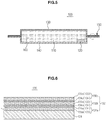
- FIG. 5 is a sectional view showing a state of the extension of the vacuum insulation panel according to an embodiment of the present invention before the extension is bent
- FIG. 6 is an enlarged sectional view showing the first sheathing material of the vacuum insulation panel according to an embodiment of the present invention
- FIG. 7 is an enlarged sectional view showing the second sheathing material of the vacuum insulation panel according to an embodiment of the present invention
- FIG. 8 is an enlarged sectional view showing the extension of the vacuum insulation panel according to an embodiment of the present invention.
- the first sheathing material 130 may include an aluminium deposited sheathing material and the second sheathing material 140 may include an aluminium foil sheathing material.
- the first sheathing material 130 will be referred to as an aluminium deposited sheathing material and the second sheathing material 140 will be referred to as an aluminium foil sheathing material for the convenience of description.
- the aluminium foil sheathing material 140 has low moisture and gas permeability but causes a heat bridge phenomenon (a phenomenon in which heat flows along the edge of the vacuum insulation panel), whereby heat insulation performance of the aluminium foil sheathing material may be lowered.
- the aluminium deposited sheathing material 130 has a thinner aluminium layer than the aluminium foil sheathing material, thereby preventing the occurrence of the heat bridge phenomenon.
- the aluminium deposited sheathing material 130 has high moisture and gas permeability, whereby durability of the aluminium deposited sheathing material 130 is lowered.
- the vacuum insulation panel 100 which prevents the occurrence of the heat bridge phenomenon while having improved durability, will be described.
- top means the surface directed outwardly of the vacuum insulation panel and “bottom” means the surface directed inwardly of the vacuum insulation panel, i.e. toward the core material of the vacuum insulation panel.
- bottom means the surface directed inwardly of the vacuum insulation panel, i.e. toward the core material of the vacuum insulation panel.
- the vacuum insulation panel 100 includes the core material 110, the first sheathing material 130, the second sheathing material 140, and a getter 120.
- the core material 110 may include glass fibres having an excellent heat insulation property. When panels formed of thinner glass fibres are stacked, a higher heat insulation effect may be obtained. Specifically, when a pore between the respective glass fibres is small, radiation, which is a heat insulation property, may be minimized, thereby achieving a high heat insulation effect.
- Each glass fibre may have a diameter of 3 to 6 ⁇ m and a length of 20 to 70 mm. In addition, the pore between the respective glass fibres may be 30 to 80 ⁇ m. However, the diameter and length of each glass fibre and the pore between the respective glass fibres are not limited thereto.
- the getter 120 is provided in the core material 110 to adsorb gas and/or moisture introduced into the core material 110 such that a vacuum state of the core material 110 is maintained.
- the getter 120 may be powder or have a shape, such as a predetermined block or rectangular parallelepiped.
- the getter 120 may be coated on the inner surface of the first sheathing material 130 and/or the second sheathing material 140 or the surface of the core material 110 or inserted into the core material 110.
- the getter 120 may include a gas getter and/or a moisture getter.
- the getter 120 may include 50% or less of a gas getter and/or 50% or more of a moisture getter.
- the gas getter may include a metal component.
- the gas getter may include at least one selected from among Ba, Li, Al, Ti, V, Fe, Co, Zr, Pd, Mg, and Nb.
- 0.4 to 5g of a gas getter may be contained in a volume of 0.1 m 3 of the first sheathing material 130.
- the moisture getter adsorbs and removes residual moisture in the vacuum insulation panel 100 and moisture permeated into the vacuum insulation panel 100. From 3 to 10g of a moisture getter may be contained in a volume of 0.1 m3 of the first sheathing material 130. In other words, the amount of moisture getter per unit volume is 30 - 100g/m 3 . If less than 3g of a moisture getter is used, the life span of the vacuum insulation panel 100 may be shortened. If more than 10g of a moisture getter is used, the area occupied by the getter 120 may be increased, thereby increasing thermal conductivity and manufacturing cost.
- the moisture getter may include a chemical getter including at least one selected from among CaO, BaO, MgO, and CaCl2 and a physical getter including at least one selected from among molecular sieve, active carbon, zeolite, active alumina, and MgCO3.
- the chemical getter may have a specific surface area of 10m2/g or more and the physical getter may have a specific surface area of 50m2/g or more.
- the getter 120 further includes a catalyst.
- the catalyst serves to convert gas introduced into the core material 110 into a state in which the gas is easily adsorbed by a metal component of the gas getter.
- the catalyst includes at least one selected from among CeO2, CuO, Co3O4, PdO, and SeO2.
- the first sheathing material 130 is disposed at one side of the core material 110 and the second sheathing material 140 is disposed at the other side of the core material 110 such that the second sheathing material 140 is coupled to the first sheathing material 130 to define a receiving space 160 to receive the core material 110.
- the first sheathing material 130 and the second sheathing material 140 have different thermal conductivities.
- the first sheathing material 130 and the second sheathing material 140 may be formed of different materials to have different thermal conductivities.
- the first sheathing material 130 and the second sheathing material 140 may have different thicknesses to have different thermal conductivities.
- the first sheathing material 130 and the second sheathing material 140 may have different stack structures. Specifically, the first sheathing material 130 and the second sheathing material 140 may have different layers. Although the layers constituting the first sheathing material 130 and the second sheathing material 140 are the same, the layers of the first sheathing material 130 and the second sheathing material 140 may be differently arranged.
- the first sheathing material 130 and the second sheathing material 140 may be coupled to form the extension 150 extending outward from the receiving space 160.
- the extension 150 may extend from opposite sides of the core material 110 outward.
- the first sheathing material 130 and the second sheathing material 140 are in tight contact with each other at the extension 150 to maintain a vacuum state of the receiving space 160, in which the core material 110 is received.
- the first sheathing material 130 includes a fusion layer 131 and a plurality of blocking layers 132.
- the fusion layer 131 may be in tight contact with the surface of the core material 110.
- the fusion layer 131 may include at least one selected from among linear low-density polyethylene (LLDPE), low density polyethylene (LDPE), high density polyethylene (HDPE), and casting polypropylene (CPP), which have high sealability.
- LLDPE linear low-density polyethylene
- LDPE low density polyethylene
- HDPE high density polyethylene
- CPP casting polypropylene
- the fusion layer 131 may be formed of a film.
- the blocking layers 132 may be stacked at the top of the fusion layer 131.
- the blocking layers 132 may include a base layer 133 and a deposition layer 134.
- the deposition layer 134 may be formed by physical deposition including evaporation, sputtering, and aerosol deposition or chemical deposition including chemical vapor deposition (CVD).
- the blocking layers 132 include a first blocking layer 132a, a second blocking layer 132b, and a third blocking layer 132c.
- the first blocking layer 132a located at the top of the fusion layer 131 so as to face the fusion layer 131 includes a first base layer 133a to surround the fusion layer 131 and a first deposition layer 134a disposed at the top of the first base layer 133a.
- the second blocking layer 132b located at the top of the first blocking layer 132a so as to face the first blocking layer 132a includes a second base layer 133b disposed at the top of the first deposition layer 134a and a second deposition layer 134b located between the first deposition layer 134a and the second base layer 133b. That is, the second blocking layer 132b is stacked at the top of the first blocking layer 132a such that the first deposition layer 134a and the second deposition layer 134b face each other.
- the third blocking layer 132c located at the top of the second blocking layer 132b includes a third deposition layer 134c disposed at the top of the second base layer 133b and a third base layer 133c located at the top of the third deposition layer 134c so as to be disposed at the outermost side of the first sheathing material 130.
- the second blocking layer 132b is stacked at the top of the first blocking layer 132a such that the first deposition layer 134a and the second deposition layer 134b face each other in order to prevent cracks from being generated in the first deposition layer 134a.
- first deposition layer 134a is in tight contact with the fusion layer 131, cracks may be generated in the first deposition layer 134a due to properties of the fusion layer 131.
- second blocking layer 132b is stacked at the top of the first blocking layer 132a such that the first deposition layer 134a and the second deposition layer 134b face each other.
- the blocking layers 132 has a structure in which the base layer 133 and the deposition layer 134 located at the top of the base layer 133 are opposite to each other.
- the second sheathing material 140 may include a sealing layer 141, an inner layer 142, a prevention layer 143, and a protection layer 144.
- the sealing layer 141 may be in tight contact with the surface of the core material 110 to surround the core material 110 together with the fusion layer 131 of the first sheathing material 130.
- the sealing layer 141 may include at least one selected from among linear low-density polyethylene (LLDPE), low density polyethylene (LDPE), high density polyethylene (HDPE), and casting polypropylene (CPP), which have high sealability.
- LLDPE linear low-density polyethylene
- LDPE low density polyethylene
- HDPE high density polyethylene
- CPP casting polypropylene
- the sealing layer 141 may have a thickness of 10 to 50 ⁇ m.
- the inner layer 142 may be located at the top of the sealing layer 141.
- the inner layer 142 may include at least one selected from among polyethylene phthalate (PET), vacuum metalized polyethylene phthalate (VMPET), ethylene vinyl alcohol (EVOH), and nylon.
- PET polyethylene phthalate
- VMPET vacuum metalized polyethylene phthalate
- EVOH ethylene vinyl alcohol
- nylon nylon
- the inner layer 142 may have a thickness of 5 to 30 ⁇ m.
- the prevention layer 143 may be provided between the sealing layer 141 and the inner layer 142.
- the prevention layer 143 may include aluminium (Al).
- the prevention layer 143 may have a thickness of 5 to 30 ⁇ m.
- the protection layer 144 absorbs and disperses external impact to protect the surface of the vacuum insulation panel 100 or the core material 110 in the vacuum insulation panel 100 from the external impact. To this end, the protection layer 144 is formed of a high impact resistant material.
- the protection layer 144 may be disposed at the top of the inner layer 142. That is, the protection layer 144 may be located at the outermost side of the second sheathing material 140.
- the protection layer 144 may include at least one selected from among polyethylene phthalate (PET), oriented polypropylene (OPP), nylon, and oriented nylon.
- PET polyethylene phthalate
- OPP oriented polypropylene
- nylon oriented nylon
- the protection layer 144 may have a thickness of 10 to 30 ⁇ m.
- the first sheathing material 130 and the second sheathing material 140 may be in tight contact with each other at the extension 150 such that the fusion layer 131 and the sealing layer 141 contact each other.
- FIG. 9 is a sectional view showing a bent state of the extension of the vacuum insulation panel according to the embodiment of the present invention. For reference numerals which are not shown, see FIGS. 1 to 8 .
- the extension 150 of the vacuum insulation panel 100 may be bent.
- the extension 150 may be bent such that the second sheathing material 140 is located between the core material 110 and the first sheathing material 130. That is, the extension 150 may be bent such that the first sheathing material 130 having low thermal conductivity is located outside the second sheathing material 140 having high thermal conductivity. As previously described with reference to FIGS.i to 4, the first sheathing material 130 may be disposed between the inner liner 11 and the outer liner 13 so as to be in tight contact with the inner side of the outer liner 13. In addition, the extension 150 is bent such that the second sheathing material 140 having high thermal conductivity is far from the outer liner 13, thereby improving heat insulation performance of the vacuum insulation panel 100.
- FIG. 10 is a graph showing thermal conductivities in a case in which no getter is used (first example), in a case in which a chemical moisture getter is used (second example), and in a case in which a chemical moisture getter and a gas getter are used (third example).
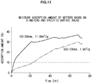
- FIG. 11 is a graph showing moisture adsorption amounts of getters having different diameters and specific surface areas
- FIG. 12 is a graph showing thermal conductivities of vacuum insulation panels using getters having different diameters and specific surface areas shown in FIG. 11 .
- the graph of FIG. 11 suggests that a getter having a smaller diameter and a larger specific surface area absorbs a larger amount of moisture than a getter having a larger diameter and a smaller specific surface area.
- the graph of FIG. 11 suggests that a vacuum insulation panel using a getter having a smaller diameter and a larger specific surface area has lower thermal conductivity than a vacuum insulation panel using a getter having a larger diameter and a smaller specific surface area. That is, as shown in FIGS. 11 and 12 , the specific surface area of the getter is inversely proportional to the thermal conductivity of the vacuum insulation panel. A vacuum insulation panel using a larger specific surface area getter exhibits lower thermal conductivity and thus excellent heat insulation performance.
- FIG. 13 is a graph showing initial thermal conductivities of the vacuum insulation panel according to an embodiment of the present invention and a conventional vacuum insulation panel (a vacuum insulation panel using only an aluminium foil sheathing material).
- the initial thermal conductivity of the vacuum insulation panel according to an embodiment of the present invention is 77.7% lower than that of the conventional vacuum insulation panel when the size of the vacuum insulation panel is 290mm x 410mm and is 73.8% lower than that of the conventional vacuum insulation panel when the size of the vacuum insulation panel is 300mm x 960mm.
- the vacuum insulation panel 100 according to the present invention may be used for various products requiring heat insulation in addition to the refrigerator.
- a vacuum insulation panel uses a hybrid sheathing material formed by a first sheathing material and a second sheathing material having different thermal conductivities when being coupled such that a glass fibre core material is received in the hybrid sheathing material, thereby reducing moisture and gas permeability and, at the same time, preventing the occurrence of a heat bridge phenomenon.
- a thin vacuum insulation panel having high heat insulation performance is used between an outer liner and an inner liner of a refrigerator, thereby embodying a slim refrigerator and, at the same time, increasing storage capacity of the refrigerator.
Landscapes
- Engineering & Computer Science (AREA)
- General Engineering & Computer Science (AREA)
- Mechanical Engineering (AREA)
- Chemical & Material Sciences (AREA)
- Combustion & Propulsion (AREA)
- Physics & Mathematics (AREA)
- Thermal Sciences (AREA)
- Thermal Insulation (AREA)
- Refrigerator Housings (AREA)
- Laminated Bodies (AREA)
Description
- The present invention relates to a vacuum insulation panel having an improved structure to improve its insulating properties and a refrigerator including the same.
- Energy is limited and global warming caused by carbon dioxide generated during the use of energy is one of the most critical problems with an energy crisis. As a result, energy regulations have been gradually strengthened in every country and an energy rating system for electric home appliances is a task to be settled by manufacturers. The energy rating system, which is provided to achieve the maximum efficiency using a small amount of energy, coincides with consumers' demand, such as high capacity and low power consumption. In particular, much research has been conducted into rendering refrigerators more efficient for the last several decades. Research for improvement in efficiency of a refrigeration cycle, a compressor, and heat exchanger has reached the limit. In recent years, therefore, research has been mainly conducted into heat loss and various attempts to improve energy efficiency by enhancing heat insulation performance of the refrigerator have been made.
- A conventional insulation panel, such as polyurethane, has a thermal conductivity of about 20mW/m.K. When this insulation panel is used, the thickness of the outer wall of the refrigerator is increased which reduces the storage capacity of the refrigerator. Consequently, it may be necessary to use a vacuum insulation panel exhibiting high heat insulation performance.
-
JP 2011 122739 -
JP 2008 008353 - However, a heat bridge phenomenon (a phenomenon in which heat flows along the edge of the vacuum insulation panel) of the vacuum insulation panel conflicts with durability of the vacuum insulation panel. As a result, manufacturing an efficient vacuum insulation panel is limited.
- It is an aspect of the present invention to provide a vacuum insulation panel having an improved structure to prevent the occurrence of a heat bridge phenomenon and a refrigerator including the same.
- It is another aspect of the present invention to provide a vacuum insulation panel having an improved structure to prevent the occurrence of a heat bridge phenomenon and to improve durability and a refrigerator including the same.
- It is a further aspect of the present invention to provide a vacuum insulation panel having an improved structure to improve a heat insulation effect and to reduce the size thereof and a refrigerator including the same.
- Additional aspects of the invention will be set forth in part in the description which follows and, in part, will be obvious from the description, or may be learned by practice of the invention.
- According to an aspect of the present invention, there is provided a vacuum insulation panel according to
claim 1. - Optional features are set out in the dependent claims.
- According to the present invention, a vacuum insulation panel includes a core material, a first sheathing material disposed outside the core material, and a second sheathing material having different thermal conductivity from the first sheathing material, the second sheathing material being coupled to the first sheathing material to form a receiving space to receive the core material.
- The first sheathing material and the second sheathing material may be coupled to form an extension extending outward from the receiving space.
- The first sheathing material may have lower thermal conductivity than the second sheathing material, and the extension may be bent such that the second sheathing material is located between the core material and the first sheathing material.
- The first sheathing material may include an aluminium deposited sheathing material, and the second sheathing material may include an aluminium foil sheathing material.
- The core material may include glass fibres, and each glass fibre may have a diameter of 3 to 6 µm and a length of 20 to 70 mm.
- The vacuum insulation panel includes further a getter provided in the core material to adsorb at least one selected from between gas and moisture introduced into the core material, wherein the getter may include at least one selected from between a gas getter and a moisture getter.
- The gas getter may include at least one selected from among Ba, Li, Al, Ti, V, Fe, Co, Zr, Pd, Mg, and Nb.
- 3 to 10g of the moisture getter may be contained in a volume of 0.1 m3 of the first sheathing material.
- The moisture getter may include a chemical getter and a physical getter, the chemical getter may include at least one selected from among CaO, BaO, MgO, and CaCl2, and the physical getter may include at least one selected from among molecular sieve, active carbon, zeolite, active alumina, and MgCO3.
- The chemical getter may have a specific surface area of 10m2/g or more, and the physical getter may have a specific surface area of 50m2/g or more.
- The getter includes a catalyst to improve activity of the getter, and the catalyst may include at least one selected from among CeO2, CuO, Co3O4, PdO, and SeO2.
- The first sheathing material includes fusion layer and a plurality of blocking layers stacked outside the fusion layer, and each of the blocking layers includes a base layer and a deposition layer provided on the base layer to block gas and moisture introduced toward the core material.
- The blocking layer includes a plurality of blocking layers, and the blocking layers are stacked such that the base layer and the deposition layer located on the base layer are opposite to each other.
- A first blocking layer, of the blocking layers, facing the fusion layer includes a first base layer to surround the fusion layer and a first deposition layer located outside the first base layer.
- A second blocking layer, of the blocking layers, facing the first blocking layer includes a second deposition layer facing the first deposition layer and a second base layer located outside the second deposition layer.
- The deposition layer may have a thickness of 10 to 100nm.
- The second sheathing material may include a sealing layer to surround the core material, an inner layer provided outside the sealing layer, a prevention layer located between the sealing layer and the inner layer, and a protection layer disposed outside the inner layer to absorb external impact.
- In accordance with another aspect of the present invention, a refrigerator includes an outer liner forming an external appearance thereof, inner liner provided in the outer liner to form a storage compartment, and a vacuum insulation panel located between the outer liner and the inner liner, wherein the vacuum insulation panel includes a core material including glass fibres, a getter provided in the core material to adsorb at least one selected from between gas and moisture introduced into the core material, a first sheathing material disposed outside the core material so as to face an inner surface of the outer liner, and a second sheathing material having higher thermal conductivity than the first sheathing material, the second sheathing material being coupled to the first sheathing material so as to face an outer surface of the inner liner to form a receiving space to receive the core material.
- The first sheathing material and the second sheathing material may be coupled to form an extension extending outward from the receiving space, and the extension may be bent toward the inner liner such that the second sheathing material is located between the core material and the first sheathing material.
- Each glass fibre may have a diameter of 3 to 6 µm and a length of 20 to 70 mm.
- The getter may include a gas getter and a moisture getter, the gas getter may include at least one selected from among Ba, Li, Al, Ti, V, Fe, Co, Zr, Pd, Mg, and Nb, and the moisture getter may include a chemical getter including at least one selected from among CaO, BaO, MgO, and CaCl2, and a physical getter including at least one selected from among molecular sieve, active carbon, zeolite, active alumina, and MgCO3.
- The
getter 2. includes a catalyst to improve activity of the getter, and the catalyst includes at least one selected from among CeO2, CuO, Co3O4, PdO, and SeO2. The first sheathing material may include an aluminium deposited sheathing material, the first sheathing material may include a fusion layer to surround the core material and a blocking layer stacked outside the fusion layer, and the blocking layer may include a base layer and a deposition layer provided on the base layer to block gas and moisture introduced toward the core material. - The deposition layer may have a thickness of 10 to 100nm.
- The deposition layer may be formed by physical deposition including evaporation, sputtering, and aerosol deposition or chemical deposition including chemical vapor deposition (CVD).
- The first sheathing material may be coupled to the inner surface of the outer liner.
- In accordance with another aspect of the present invention, a vacuum insulation panel includes a core material including glass fibres, a getter provided in the core material to adsorb gas and moisture introduced into the core material such that a vacuum state of the core material is maintained, an aluminium deposited sheathing material disposed outside the core material, and an aluminium foil sheathing material coupled to the aluminium deposited sheathing material to form a receiving space to receive the core material, wherein the aluminium deposited sheathing material and the aluminium foil sheathing material are coupled to form an extension extending outward from the receiving space.
- The extension may be bent such that the aluminium deposited sheathing material having low thermal conductivity is located outside the aluminium foil sheathing material.
- The aluminium deposited sheathing material may include a fusion layer facing the core material and a blocking layer stacked outside the fusion layer.
- The aluminium foil sheathing material may include a sealing layer to surround the core material, an inner layer provided outside the sealing layer, a prevention layer located between the sealing layer and the inner layer, and a protection layer disposed outside the inner layer to absorb external impact.
- The fusion layer and the sealing layer may be in contact with each other at the extension.
- In accordance with a further aspect of the present invention, a vacuum insulation panel includes a core material, a getter provided in the core material to adsorb gas and moisture introduced into the core material, a first sheathing material disposed outside the core material, and a second sheathing material having a different stack structure from the first sheathing material, the second sheathing material being coupled to the first sheathing material to form a receiving space to receive the core material.
- Pores of about 30 - 80 µm are formed between the glass fibres.
- The first sheathing material is made from a material that is different than the second sheathing material.
- A thickness of the first sheathing material is different that a thickness of the second sheathing material.
- These and/or other aspects of the invention will become apparent and more readily appreciated from the following description of the embodiments, taken in conjunction with the accompanying drawings in which:
-
FIG. 1 is a perspective view showing an external appearance of a refrigerator according to an embodiment of the present invention; -
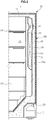
FIG. 2 is a sectional view showing the refrigerator according to an embodiment of the present invention; -
FIG. 3 is a partially enlarged sectional view ofFIG. 2 ; -
FIG. 4 is a perspective view showing a vacuum insulation panel according to an embodiment of the present invention; -
FIG. 5 is a sectional view showing a state of an extension of the vacuum insulation panel according to the embodiment of the present invention before the extension is bent; -
FIG. 6 is an enlarged sectional view showing a first sheathing material of the vacuum insulation panel according to an embodiment of the present invention; -
FIG. 7 is an enlarged sectional view showing a second sheathing material of the vacuum insulation panel according to an embodiment of the present invention; -
FIG. 8 is an enlarged sectional view showing the extension of the vacuum insulation panel ofFIG. 5 according to an embodiment of the present invention; -
FIG. 9 is a sectional view showing a bent state of the extension of the vacuum insulation panel according to an embodiment of the present invention; -
FIG. 10 is a graph showing thermal conductivities in a case in which no getter is used (first example), in a case in which a chemical moisture getter is used (second example), and in a case in which a chemical moisture getter and a gas getter are used (third example); -
FIG. 11 is a graph showing moisture adsorption amounts of getters having different diameters and specific surface areas; -
FIG. 12 is a graph showing thermal conductivities of vacuum insulation panels using the getters having different diameters and specific surface areas shown inFIG. 11 ; and -
FIG. 13 is a graph showing initial thermal conductivities of the vacuum insulation panel according to the embodiment of the present invention and a conventional vacuum insulation panel. - Now, preferred embodiments of the present invention will be described in detail with reference to the annexed drawings. Terms such as "upper part," "lower part," "upper end," and "lower end" are defined based on the drawings and do not limit shapes and positions of components.
- As shown in
FIGS. 1 to 4 , therefrigerator 1 may include amain body 10 forming the external appearance thereof and astorage compartment 20 provided in themain body 10 with the front being open. - The
main body 10 includes aninner liner 11 forming thestorage compartment 20 and anouter liner 13 forming the external appearance thereof. In addition, themain body 10 further includes a cool air supply device to supply cool air to thestorage compartment 20. - The cool air supply device may include a compressor C, a condenser (not shown), an expansion valve (not shown), an
evaporator 26, and a blowingfan 27. Between theinner liner 11 and theouter liner 13 of themain body 10 is interposed a foamedinsulation panel 15 to prevent leakage of cool air from thestorage compartment 20. - At the rear lower side of the
main body 10 is provided amachinery compartment 23, in which the compressor C to compress refrigerant and the condenser to condense the compressed refrigerant are installed. - The
storage compartment 20 is partitioned into left and right sides by apartition 17. A refrigeratingcompartment 21 is provided at one area of themain body 10 and a freezingcompartment 22 is provided at another area of themain body 10. - The
refrigerator 10 may further include adoor 30 to open and close thestorage compartment 20. - The refrigerating
compartment 21 and the freezingcompartment 22 are opened and closed by a refrigeratingcompartment door 31 and a freezingcompartment door 33 hinged to themain body 10, respectively. A plurality ofbins 35, in which foods are received, is provided at the rears of the refrigeratingcompartment door 31 and the freezingcompartment door 33. - A plurality of
shelves 24 is provided in thestorage compartment 20 to partition thestorage compartment 20 into a plurality of spaces. Foods are loaded on eachshelf 24. - In addition, a plurality of
storage boxes 25 is provided in thestorage compartment 20 such that thestorage boxes 25 may be inserted into or removed from thestorage compartment 20 in a sliding fashion. - The
refrigerator 1 may further include ahinge module 40 including anupper hinge 41 and alower hinge 43, by which thedoor 30 is hinged to themain body 10. - A foam space S is provided between the
inner liner 11 forming thestorage compartment 20 and theouter liner 13 coupled to the outside of theinner liner 11 to form the external appearance of themain body 10. The foam space S is filled with the foamedinsulation panel 15. - In order to improve insulativity of the foamed
insulation panel 15, the foam space S may be filled with a vacuum insulation panel (VIP) 100 in addition to the foamedinsulation panel 15. - The
vacuum insulation panel 100 includes acore material 110 andsheathing materials sheathing materials vacuum insulation panel 100 to maintain the life span of thevacuum insulation panel 100. - The
sheathing materials vacuum insulation panel 100 includes afirst sheathing material 130 and asecond sheathing material 140. - The
first sheathing material 130 and thesecond sheathing material 140 have different thermal conductivities. Specifically, thefirst sheathing material 130 having low thermal conductivity may be disposed outside thecore material 110 so as to face aninner surface 13a of theouter liner 13. Thesecond sheathing material 140 having high thermal conductivity may be disposed outside thecore material 110 so as to face anouter surface 11a of theinner liner 11 or may be coupled to thefirst sheathing material 130 to define a receiving space (not shown) to receive thecore material 110. - The
first sheathing material 130 may be in tight contact withinner surface 13a of theouter liner 13. Since thefirst sheathing material 130 having low thermal conductivity is in tight contact with theinner surface 13a of theouter liner 13, heat insulation performance may be improved and external moisture and gas may be prevented from being introduced into thevacuum insulation panel 100. In addition, since the outer surface of thefirst sheathing material 130 facing theinner surface 13a of theouter liner 13 is flat, the outer surface of thefirst sheathing material 130 may easily come into tight contact with theinner surface 13a of theouter liner 13. Since an extension 150 (seeFIG. 5 ), formed by thefirst sheathing material 130 and thesecond sheathing material 140 when being coupled, is bent toward theinner liner 11 such that thefirst sheathing material 130 having low thermal conductivity is located outside thesecond sheathing material 140, the outer surface of thesecond sheathing material 140 may not be flat. - However, the
first sheathing material 130 is not limited to being in tight contact with theinner surface 13a of theouter liner 13. Instead of thefirst sheathing material 130, thesecond sheathing material 140 may be in tight contact with theinner surface 13a of theouter liner 13. -
FIG. 5 is a sectional view showing a state of the extension of the vacuum insulation panel according to an embodiment of the present invention before the extension is bent,FIG. 6 is an enlarged sectional view showing the first sheathing material of the vacuum insulation panel according to an embodiment of the present invention,FIG. 7 is an enlarged sectional view showing the second sheathing material of the vacuum insulation panel according to an embodiment of the present invention,FIG. 8 is an enlarged sectional view showing the extension of the vacuum insulation panel according to an embodiment of the present invention. - The
first sheathing material 130 may include an aluminium deposited sheathing material and thesecond sheathing material 140 may include an aluminium foil sheathing material. Hereinafter, thefirst sheathing material 130 will be referred to as an aluminium deposited sheathing material and thesecond sheathing material 140 will be referred to as an aluminium foil sheathing material for the convenience of description. The aluminiumfoil sheathing material 140 has low moisture and gas permeability but causes a heat bridge phenomenon (a phenomenon in which heat flows along the edge of the vacuum insulation panel), whereby heat insulation performance of the aluminium foil sheathing material may be lowered. On the other hand, the aluminium depositedsheathing material 130 has a thinner aluminium layer than the aluminium foil sheathing material, thereby preventing the occurrence of the heat bridge phenomenon. However, the aluminium depositedsheathing material 130 has high moisture and gas permeability, whereby durability of the aluminium depositedsheathing material 130 is lowered. - Hereinafter, the
vacuum insulation panel 100 according to the embodiment of the present invention, which prevents the occurrence of the heat bridge phenomenon while having improved durability, will be described. - In the following description, the term "top" means the surface directed outwardly of the vacuum insulation panel and "bottom" means the surface directed inwardly of the vacuum insulation panel, i.e. toward the core material of the vacuum insulation panel. For reference numerals which are not shown, see
FIGS. 1 to 4 . - As shown in
FIGS. 5 to 8 , thevacuum insulation panel 100 includes thecore material 110, thefirst sheathing material 130, thesecond sheathing material 140, and agetter 120. - The
core material 110 may include glass fibres having an excellent heat insulation property. When panels formed of thinner glass fibres are stacked, a higher heat insulation effect may be obtained. Specifically, when a pore between the respective glass fibres is small, radiation, which is a heat insulation property, may be minimized, thereby achieving a high heat insulation effect. Each glass fibre may have a diameter of 3 to 6 µm and a length of 20 to 70 mm. In addition, the pore between the respective glass fibres may be 30 to 80 µm. However, the diameter and length of each glass fibre and the pore between the respective glass fibres are not limited thereto. - The
getter 120 is provided in thecore material 110 to adsorb gas and/or moisture introduced into thecore material 110 such that a vacuum state of thecore material 110 is maintained. Thegetter 120 may be powder or have a shape, such as a predetermined block or rectangular parallelepiped. In addition, thegetter 120 may be coated on the inner surface of thefirst sheathing material 130 and/or thesecond sheathing material 140 or the surface of thecore material 110 or inserted into thecore material 110. - The
getter 120 may include a gas getter and/or a moisture getter. When thegetter 120 includes both the gas getter and the moisture getter, thegetter 120 may include 50% or less of a gas getter and/or 50% or more of a moisture getter. - The gas getter may include a metal component. Specifically, the gas getter may include at least one selected from among Ba, Li, Al, Ti, V, Fe, Co, Zr, Pd, Mg, and Nb. 0.4 to 5g of a gas getter may be contained in a volume of 0.1 m3 of the
first sheathing material 130. - The moisture getter adsorbs and removes residual moisture in the
vacuum insulation panel 100 and moisture permeated into thevacuum insulation panel 100. From 3 to 10g of a moisture getter may be contained in a volume of 0.1 m3 of thefirst sheathing material 130. In other words, the amount of moisture getter per unit volume is 30 - 100g/m3. If less than 3g of a moisture getter is used, the life span of thevacuum insulation panel 100 may be shortened. If more than 10g of a moisture getter is used, the area occupied by thegetter 120 may be increased, thereby increasing thermal conductivity and manufacturing cost. - The moisture getter may include a chemical getter including at least one selected from among CaO, BaO, MgO, and CaCl2 and a physical getter including at least one selected from among molecular sieve, active carbon, zeolite, active alumina, and MgCO3. The higher the specific surface area is, the higher the adsorption performance of the
getter 120 is. The chemical getter may have a specific surface area of 10m2/g or more and the physical getter may have a specific surface area of 50m2/g or more. - The
getter 120 further includes a catalyst. - The catalyst serves to convert gas introduced into the
core material 110 into a state in which the gas is easily adsorbed by a metal component of the gas getter. The catalyst includes at least one selected from among CeO2, CuO, Co3O4, PdO, and SeO2. - The
first sheathing material 130 is disposed at one side of thecore material 110 and thesecond sheathing material 140 is disposed at the other side of thecore material 110 such that thesecond sheathing material 140 is coupled to thefirst sheathing material 130 to define a receivingspace 160 to receive thecore material 110. As previously described, thefirst sheathing material 130 and thesecond sheathing material 140 have different thermal conductivities. - The
first sheathing material 130 and thesecond sheathing material 140 may be formed of different materials to have different thermal conductivities. In addition, thefirst sheathing material 130 and thesecond sheathing material 140 may have different thicknesses to have different thermal conductivities. - The
first sheathing material 130 and thesecond sheathing material 140 may have different stack structures. Specifically, thefirst sheathing material 130 and thesecond sheathing material 140 may have different layers. Although the layers constituting thefirst sheathing material 130 and thesecond sheathing material 140 are the same, the layers of thefirst sheathing material 130 and thesecond sheathing material 140 may be differently arranged. - The
first sheathing material 130 and thesecond sheathing material 140 may be coupled to form theextension 150 extending outward from the receivingspace 160. Theextension 150 may extend from opposite sides of thecore material 110 outward. Thefirst sheathing material 130 and thesecond sheathing material 140 are in tight contact with each other at theextension 150 to maintain a vacuum state of the receivingspace 160, in which thecore material 110 is received. - The
first sheathing material 130 includes afusion layer 131 and a plurality of blocking layers 132. - The
fusion layer 131 may be in tight contact with the surface of thecore material 110. Thefusion layer 131 may include at least one selected from among linear low-density polyethylene (LLDPE), low density polyethylene (LDPE), high density polyethylene (HDPE), and casting polypropylene (CPP), which have high sealability. In addition, thefusion layer 131 may be formed of a film. - The blocking layers 132 may be stacked at the top of the
fusion layer 131. The blocking layers 132 may include abase layer 133 and adeposition layer 134. - The
deposition layer 134 may be formed by physical deposition including evaporation, sputtering, and aerosol deposition or chemical deposition including chemical vapor deposition (CVD). - Aluminium (Al) may be deposited on the
deposition layer 134. However, other metals may be deposited on thedeposition layer 134. In addition, thedeposition layer 134 may have a thickness of 10 to 100nm. According to the present invention, the blockinglayers 132 include afirst blocking layer 132a, asecond blocking layer 132b, and athird blocking layer 132c. - The
first blocking layer 132a located at the top of thefusion layer 131 so as to face thefusion layer 131 includes afirst base layer 133a to surround thefusion layer 131 and afirst deposition layer 134a disposed at the top of thefirst base layer 133a. - The
second blocking layer 132b located at the top of thefirst blocking layer 132a so as to face thefirst blocking layer 132a includes asecond base layer 133b disposed at the top of thefirst deposition layer 134a and asecond deposition layer 134b located between thefirst deposition layer 134a and thesecond base layer 133b. That is, thesecond blocking layer 132b is stacked at the top of thefirst blocking layer 132a such that thefirst deposition layer 134a and thesecond deposition layer 134b face each other. - The
third blocking layer 132c located at the top of thesecond blocking layer 132b includes athird deposition layer 134c disposed at the top of thesecond base layer 133b and athird base layer 133c located at the top of thethird deposition layer 134c so as to be disposed at the outermost side of thefirst sheathing material 130. - The
second blocking layer 132b is stacked at the top of thefirst blocking layer 132a such that thefirst deposition layer 134a and thesecond deposition layer 134b face each other in order to prevent cracks from being generated in thefirst deposition layer 134a. Specifically, if thefirst deposition layer 134a is in tight contact with thefusion layer 131, cracks may be generated in thefirst deposition layer 134a due to properties of thefusion layer 131. If cracks are generated in thefirst deposition layer 134a, gas and moisture may be introduced into thevacuum insulation panel 100 through the cracks, thereby lowering heat insulation performance of thevacuum insulation panel 100. For this reason, thesecond blocking layer 132b is stacked at the top of thefirst blocking layer 132a such that thefirst deposition layer 134a and thesecond deposition layer 134b face each other. - The blocking layers 132 has a structure in which the
base layer 133 and thedeposition layer 134 located at the top of thebase layer 133 are opposite to each other. - The
second sheathing material 140 may include asealing layer 141, aninner layer 142, aprevention layer 143, and aprotection layer 144. - The
sealing layer 141 may be in tight contact with the surface of thecore material 110 to surround thecore material 110 together with thefusion layer 131 of thefirst sheathing material 130. Thesealing layer 141 may include at least one selected from among linear low-density polyethylene (LLDPE), low density polyethylene (LDPE), high density polyethylene (HDPE), and casting polypropylene (CPP), which have high sealability. In addition, thesealing layer 141 may have a thickness of 10 to 50 µm. - The
inner layer 142 may be located at the top of thesealing layer 141. Theinner layer 142 may include at least one selected from among polyethylene phthalate (PET), vacuum metalized polyethylene phthalate (VMPET), ethylene vinyl alcohol (EVOH), and nylon. Theinner layer 142 may have a thickness of 5 to 30 µm. - The
prevention layer 143 may be provided between thesealing layer 141 and theinner layer 142. Theprevention layer 143 may include aluminium (Al). Theprevention layer 143 may have a thickness of 5 to 30 µm. - The
protection layer 144 absorbs and disperses external impact to protect the surface of thevacuum insulation panel 100 or thecore material 110 in thevacuum insulation panel 100 from the external impact. To this end, theprotection layer 144 is formed of a high impact resistant material. - The
protection layer 144 may be disposed at the top of theinner layer 142. That is, theprotection layer 144 may be located at the outermost side of thesecond sheathing material 140. Theprotection layer 144 may include at least one selected from among polyethylene phthalate (PET), oriented polypropylene (OPP), nylon, and oriented nylon. Theprotection layer 144 may have a thickness of 10 to 30 µm. - The
first sheathing material 130 and thesecond sheathing material 140 may be in tight contact with each other at theextension 150 such that thefusion layer 131 and thesealing layer 141 contact each other. -
FIG. 9 is a sectional view showing a bent state of the extension of the vacuum insulation panel according to the embodiment of the present invention. For reference numerals which are not shown, seeFIGS. 1 to 8 . - As shown in
FIG. 9 , theextension 150 of thevacuum insulation panel 100 may be bent. - The
extension 150 may be bent such that thesecond sheathing material 140 is located between thecore material 110 and thefirst sheathing material 130. That is, theextension 150 may be bent such that thefirst sheathing material 130 having low thermal conductivity is located outside thesecond sheathing material 140 having high thermal conductivity. As previously described with reference to FIGS.i to 4, thefirst sheathing material 130 may be disposed between theinner liner 11 and theouter liner 13 so as to be in tight contact with the inner side of theouter liner 13. In addition, theextension 150 is bent such that thesecond sheathing material 140 having high thermal conductivity is far from theouter liner 13, thereby improving heat insulation performance of thevacuum insulation panel 100. -
FIG. 10 is a graph showing thermal conductivities in a case in which no getter is used (first example), in a case in which a chemical moisture getter is used (second example), and in a case in which a chemical moisture getter and a gas getter are used (third example). - As shown in
FIG. 10 , in a case in which no getter is used (first example), initial thermal conductivity and even long-term thermal conductivity are higher than in cases in which a getter(s) is used (second and third examples), whereby heat insulation performance is lowered. In each case, a glass fibre core material is used. In a case in which both a chemical moisture getter and a gas getter are used to adsorb both moisture and gas (third example), thermal conductivity is lower than in either the case in which no getter is used (first example) and the case in which only a moisture getter is used (second example). -
FIG. 11 is a graph showing moisture adsorption amounts of getters having different diameters and specific surface areas andFIG. 12 is a graph showing thermal conductivities of vacuum insulation panels using getters having different diameters and specific surface areas shown inFIG. 11 . - The graph of
FIG. 11 suggests that a getter having a smaller diameter and a larger specific surface area absorbs a larger amount of moisture than a getter having a larger diameter and a smaller specific surface area. - The graph of
FIG. 11 suggests that a vacuum insulation panel using a getter having a smaller diameter and a larger specific surface area has lower thermal conductivity than a vacuum insulation panel using a getter having a larger diameter and a smaller specific surface area. That is, as shown inFIGS. 11 and12 , the specific surface area of the getter is inversely proportional to the thermal conductivity of the vacuum insulation panel. A vacuum insulation panel using a larger specific surface area getter exhibits lower thermal conductivity and thus excellent heat insulation performance. -
FIG. 13 is a graph showing initial thermal conductivities of the vacuum insulation panel according to an embodiment of the present invention and a conventional vacuum insulation panel (a vacuum insulation panel using only an aluminium foil sheathing material). - As shown in
FIG. 13 , the initial thermal conductivity of the vacuum insulation panel according to an embodiment of the present invention is 77.7% lower than that of the conventional vacuum insulation panel when the size of the vacuum insulation panel is 290mm x 410mm and is 73.8% lower than that of the conventional vacuum insulation panel when the size of the vacuum insulation panel is 300mm x 960mm. - The
vacuum insulation panel 100 according to the present invention may be used for various products requiring heat insulation in addition to the refrigerator. - As is apparent from the above description, a vacuum insulation panel according to the present invention uses a hybrid sheathing material formed by a first sheathing material and a second sheathing material having different thermal conductivities when being coupled such that a glass fibre core material is received in the hybrid sheathing material, thereby reducing moisture and gas permeability and, at the same time, preventing the occurrence of a heat bridge phenomenon.
- A thin vacuum insulation panel having high heat insulation performance is used between an outer liner and an inner liner of a refrigerator, thereby embodying a slim refrigerator and, at the same time, increasing storage capacity of the refrigerator.
- Although a few embodiments of the present invention have been shown and described, it would be appreciated by those skilled in the art that changes may be made in these embodiments without departing from the principles of the invention, the scope of which is defined in the claims.
Claims (9)
- A vacuum insulation panel (100) comprising:a core material (110);a first sheathing material (130) disposed outside the core material (110);a second sheathing material (140) having different thermal conductivity from the first sheathing material (130), the second sheathing material (140) being coupled to the first sheathing material (130) to form a receiving space (160) to receive the core material (110); andwherein the first sheathing material (130) includes a fusion layer (131) and a plurality of blocking layers (132a, 132b, 132c) that are stacked outside the fusion layer (131), the blocking layers (132a, 132b, 132c) including a first blocking layer (132a) facing the fusion layer (131), a second blocking layer (132b) facing the first blocking layer (132a),wherein the first blocking layer (132a) includes:a first base layer (133a) surrounding the fusion layer (131); anda first deposition layer (134a) located outside and opposite to the first base layer (133a) to block gas and moisture introduced into the core material (110),wherein the second blocking layer (132b) includes:a second deposition layer (134b) facing the first deposition layer (134a) to block gas and moisture introduced into the core material (110); anda second base layer (133b) located outside and opposite to the second deposition layer (134b),characterized in that the vacuum insulation panel further comprises a getter (120) provided in the core material (110) to adsorb gas and/or moisture introduced into the core material (110), wherein the getter (120) includes a gas getter and/or a moisture getter and a catalyst to improve activity of the getter (120), and the catalyst includes at least one selected from CeO2, CuO, CO3O4, PdO and SeO2, wherein the first sheathing material further includes a third blocking layer (132c) located outside the second blocking layer (132b), wherein the third blocking layer (132c) includes:a third deposition layer (134c) located outside and opposite to the second base layer (133b); anda third base layer (133c) disposed outside the third deposition layer (134c).
- The vacuum insulation panel (100) according to claim 1, wherein the first sheathing material (130) and the second sheathing material (140) are coupled to form an extension (150) extending outwards from the receiving space (160).
- The vacuum insulation panel (100) according to claim 2, wherein
the first sheathing material (130) has lower thermal conductivity than the second sheathing material (140), and
the extension (150) is bent such that the second sheathing material (140) is located between the core material (110) and the first sheathing material (130). - The vacuum insulation panel (100) according to any one of the preceding claims, wherein
the first sheathing material (130) comprises an aluminium deposited sheathing material, and
the second sheathing material (140) comprises an aluminium foil sheathing material; and/or wherein
the core material (110) comprises glass fibres, and/or wherein
each of the glass fibres has a diameter of 3 to 6 µm and a length of 20 to 70 mm. - The vacuum insulation panel (100) according to claim 1, wherein the gas getter comprises at least one selected from Ba, Li, Al, Ti, V, Fe, Co, Zr, Pd, Mg, and Nb, wherein the first sheathing material (130) may contain 30 - 100g/m3 of the moisture getter.
- The vacuum insulation panel (100) according to claim 1 or 5, wherein
the moisture getter includes a chemical getter and/or a physical getter,
the chemical getter includes at least one selected from CaO, BaO, MgO, and CaCl2, and
the physical getter includes at least one selected from molecular sieve, active carbon, zeolite, active alumina and MgCO3, and/or wherein
the chemical getter has a specific surface area of 10m2/g or more, and
the physical getter has a specific surface area of 50m2/g or more. - The vacuum insulation panel (100) according to any one of the preceding claims, wherein the deposition layer (134a, 134b, 134c) has a thickness of 10 to 100 nm.
- The vacuum insulation panel (100) according to any one of the preceding claims, wherein the second sheathing material (140) comprises:a sealing layer (141) to surround the core material (110);an inner layer (142) provided outside the sealing layer (141);a prevention layer (143) located between the sealing layer (141) and the inner layer (142); anda protection layer (144) disposed outside the inner layer (142) to absorb external impact.
- A refrigerator (1) comprising:an outer liner (13) forming an external appearance of the refrigerator (1);an inner liner (11) provided in the outer liner (13) to form a storage compartment (20); anda vacuum insulation panel (100) according to any one of the preceding claims located between the outer liner (13) and the inner liner (11),wherein the first sheathing material (130) is arranged to face an inner surface (13a) of the outer liner (13); andthe second sheathing material (140) has higher thermal conductivity than the first sheathing material (130) and is arranged to face an outer surface (11a) of the inner liner (11).
Applications Claiming Priority (1)
| Application Number | Priority Date | Filing Date | Title |
|---|---|---|---|
| KR1020130152885A KR101752669B1 (en) | 2013-12-10 | 2013-12-10 | Vacuum heat insulating material and refrigerator including the same |
Publications (2)
| Publication Number | Publication Date |
|---|---|
| EP2884208A1 EP2884208A1 (en) | 2015-06-17 |
| EP2884208B1 true EP2884208B1 (en) | 2021-04-21 |
Family
ID=51743292
Family Applications (1)
| Application Number | Title | Priority Date | Filing Date |
|---|---|---|---|
| EP14188779.4A Active EP2884208B1 (en) | 2013-12-10 | 2014-10-14 | Vacuum insulation panel and refrigerator including a vacuum insulation panel |
Country Status (8)
| Country | Link |
|---|---|
| US (1) | US9404684B2 (en) |
| EP (1) | EP2884208B1 (en) |
| JP (1) | JP2017501350A (en) |
| KR (1) | KR101752669B1 (en) |
| CN (1) | CN104696669B (en) |
| AU (1) | AU2014360996B2 (en) |
| CA (1) | CA2933154C (en) |
| WO (1) | WO2015088241A1 (en) |
Families Citing this family (21)
| Publication number | Priority date | Publication date | Assignee | Title |
|---|---|---|---|---|
| KR20150106306A (en) * | 2014-03-11 | 2015-09-21 | 삼성전자주식회사 | Vacuum heat insulating material and refrigerator including the same |
| KR102442973B1 (en) | 2015-08-03 | 2022-09-14 | 엘지전자 주식회사 | Vacuum insulator and refrigerator |
| KR102525550B1 (en) | 2015-08-03 | 2023-04-25 | 엘지전자 주식회사 | Vacuum adiabatic body and refrigerator |
| KR102466469B1 (en) | 2015-08-03 | 2022-11-11 | 엘지전자 주식회사 | Vacuum adiabatic body and refrigerator |
| KR20170016188A (en) | 2015-08-03 | 2017-02-13 | 엘지전자 주식회사 | Vacuum adiabatic body and refrigerator |
| KR102529852B1 (en) | 2015-08-03 | 2023-05-08 | 엘지전자 주식회사 | Vacuum adiabatic body and refrigerator |
| KR102456642B1 (en) | 2015-08-03 | 2022-10-19 | 엘지전자 주식회사 | Vacuum adiabatic body and refrigerator |
| US10907887B2 (en) | 2015-08-03 | 2021-02-02 | Lg Electronics Inc. | Vacuum adiabatic body and refrigerator |
| KR102447245B1 (en) | 2015-08-03 | 2022-09-27 | 엘지전자 주식회사 | Vacuum insulator and refrigerator |
| KR102466470B1 (en) | 2015-08-04 | 2022-11-11 | 엘지전자 주식회사 | Vacuum adiabatic body and refrigerator |
| KR101787281B1 (en) * | 2016-08-31 | 2017-10-18 | 씨제이제일제당 (주) | covering material for vacuum insulating panel |
| JP2018141902A (en) * | 2017-02-28 | 2018-09-13 | エルジー ディスプレイ カンパニー リミテッド | Getter granular body and display device |
| KR102529094B1 (en) | 2018-04-05 | 2023-05-08 | 엘지전자 주식회사 | Vacuum adiabatic body and refrigerator |
| CN112188852B (en) * | 2018-05-23 | 2023-01-03 | 惠而浦公司 | Electric appliance hinge assembly |
| CN109692652A (en) * | 2019-02-20 | 2019-04-30 | 西华大学 | A kind of normal-temperature nano composite getter |
| CN110200696A (en) * | 2019-06-13 | 2019-09-06 | 北京阳光易帮医疗科技有限公司 | Vacuum heat-insulation device, its manufacturing method and cryoablation needle |
| KR20210100447A (en) * | 2020-02-06 | 2021-08-17 | 삼성전자주식회사 | Vacuum heat insulating material, the method of manufacturing the same and refrigerator including the same |
| US20210372691A1 (en) * | 2020-05-29 | 2021-12-02 | Whirlpool Corporation | Appliance liner system |
| CN111911723B (en) * | 2020-07-07 | 2021-10-08 | 山东顺发重工有限公司 | Magnetic traction type tap water pipe orifice ice resistance resisting flange ring |
| CN114834112B (en) * | 2022-05-19 | 2024-03-29 | 青岛新材料科技工业园发展有限公司 | Puncture-resistant high-heat-insulation vacuum insulation panel and preparation method thereof |
| US12320577B2 (en) * | 2023-02-21 | 2025-06-03 | Whirlpool Corporation | Refrigerator cabinet with a trim breaker and vacuum insulated panel associated with the trim breaker |
Citations (3)
| Publication number | Priority date | Publication date | Assignee | Title |
|---|---|---|---|---|
| JP2000310392A (en) * | 1999-04-28 | 2000-11-07 | Matsushita Electric Ind Co Ltd | Vacuum insulation |
| US20030134078A1 (en) * | 1999-06-30 | 2003-07-17 | Matsushita Electric Industrial Co., Ltd. | Vacuum heat insulator, hot insulating device using vacuum heat insulator, and electric water heater |
| JP2008008353A (en) * | 2006-06-28 | 2008-01-17 | Toppan Printing Co Ltd | Vacuum insulation |
Family Cites Families (23)
| Publication number | Priority date | Publication date | Assignee | Title |
|---|---|---|---|---|
| US5091233A (en) * | 1989-12-18 | 1992-02-25 | Whirlpool Corporation | Getter structure for vacuum insulation panels |
| IT1263965B (en) | 1993-02-24 | 1996-09-05 | Getters Spa | VACUUM INSULATED SHIRT SUITABLE FOR THERMAL CONTAINERS CONTAINING LIQUIDS AND IN PARTICULAR AQUOUS AND / OR ORGANIC LIQUIDS |
| US5532034A (en) | 1994-12-06 | 1996-07-02 | Whirlpool Corporation | Getter system for vacuum insulation panel |
| JP4017713B2 (en) * | 1997-09-12 | 2007-12-05 | 松下冷機株式会社 | Vacuum insulator, refrigerator, heat insulating panel, and method for manufacturing vacuum insulator |
| KR20030072717A (en) | 2002-03-06 | 2003-09-19 | 삼성전자주식회사 | The vacuum heat insulator and process for preparing the same |
| AU2003235312A1 (en) | 2002-04-22 | 2003-11-03 | Matsushita Refrigeration Company | Refrigerator |
| US20040180176A1 (en) * | 2003-03-14 | 2004-09-16 | Rusek Stanley J. | Vaccum insulation article |
| JP2005106312A (en) | 2003-09-29 | 2005-04-21 | Hitachi Home & Life Solutions Inc | Refrigerator, vacuum insulation panel and method for manufacturing the same |
| JP3856008B2 (en) | 2004-04-16 | 2006-12-13 | 松下電器産業株式会社 | Manufacturing method of vacuum insulation |
| JP4449630B2 (en) * | 2004-07-28 | 2010-04-14 | パナソニック株式会社 | VACUUM INSULATOR AND REFRIGERATOR HAVING VACUUM INSULATOR |
| JP2006118636A (en) * | 2004-10-22 | 2006-05-11 | Matsushita Electric Ind Co Ltd | Vacuum insulation and refrigerator using vacuum insulation |
| EP1851050B1 (en) | 2005-02-17 | 2011-08-03 | SAES GETTERS S.p.A. | Flexible multi-layered getter |
| JP4752422B2 (en) * | 2005-09-26 | 2011-08-17 | パナソニック株式会社 | Method for manufacturing vacuum insulator |
| JP2008126191A (en) | 2006-11-24 | 2008-06-05 | Dainippon Printing Co Ltd | Microreactor |
| JP2010065711A (en) * | 2008-09-08 | 2010-03-25 | Hitachi Appliances Inc | Vacuum heat insulating material and refrigerator using the same |
| JP2011005835A (en) * | 2009-06-29 | 2011-01-13 | Dainippon Printing Co Ltd | Gas-barrier laminated film, laminate, and vacuum heat insulating material using the same |
| EP2491324B1 (en) | 2009-10-23 | 2015-05-27 | LG Hausys, Ltd. | Vacuum insulation panel |
| JP5337681B2 (en) * | 2009-12-08 | 2013-11-06 | 株式会社東芝 | refrigerator |
| JP5398604B2 (en) * | 2010-03-17 | 2014-01-29 | 三菱電機株式会社 | Vacuum insulation material and manufacturing method thereof |
| KR101417249B1 (en) * | 2011-02-21 | 2014-07-16 | (주)엘지하우시스 | Material for vacuum insulation pannel and method for fabricating the same |
| KR101386938B1 (en) | 2011-10-18 | 2014-05-02 | 하호 | Vacumm Insulation Panel and getter-compound therefor |
| CN102494226A (en) * | 2011-12-01 | 2012-06-13 | 蔡财木 | Vacuum insulation panel with embedded parts and preparation method for vacuum heat insulation plate |
| KR101447767B1 (en) | 2011-12-02 | 2014-10-07 | (주)엘지하우시스 | Vacuum insulation panel for high operating temperature |
-
2013
- 2013-12-10 KR KR1020130152885A patent/KR101752669B1/en not_active Expired - Fee Related
-
2014
- 2014-08-28 US US14/471,018 patent/US9404684B2/en active Active
- 2014-10-14 EP EP14188779.4A patent/EP2884208B1/en active Active
- 2014-12-01 CN CN201410715032.XA patent/CN104696669B/en not_active Expired - Fee Related
- 2014-12-10 AU AU2014360996A patent/AU2014360996B2/en not_active Ceased
- 2014-12-10 CA CA2933154A patent/CA2933154C/en active Active
- 2014-12-10 JP JP2016537473A patent/JP2017501350A/en active Pending
- 2014-12-10 WO PCT/KR2014/012120 patent/WO2015088241A1/en not_active Ceased
Patent Citations (3)
| Publication number | Priority date | Publication date | Assignee | Title |
|---|---|---|---|---|
| JP2000310392A (en) * | 1999-04-28 | 2000-11-07 | Matsushita Electric Ind Co Ltd | Vacuum insulation |
| US20030134078A1 (en) * | 1999-06-30 | 2003-07-17 | Matsushita Electric Industrial Co., Ltd. | Vacuum heat insulator, hot insulating device using vacuum heat insulator, and electric water heater |
| JP2008008353A (en) * | 2006-06-28 | 2008-01-17 | Toppan Printing Co Ltd | Vacuum insulation |
Non-Patent Citations (1)
| Title |
|---|
| DATABASE WPI Week 200114, Derwent World Patents Index; AN 2001-127854 * |
Also Published As
| Publication number | Publication date |
|---|---|
| JP2017501350A (en) | 2017-01-12 |
| EP2884208A1 (en) | 2015-06-17 |
| AU2014360996B2 (en) | 2017-04-06 |
| CN104696669B (en) | 2018-09-11 |
| CA2933154C (en) | 2018-07-10 |
| CN104696669A (en) | 2015-06-10 |
| US9404684B2 (en) | 2016-08-02 |
| AU2014360996A1 (en) | 2016-06-30 |
| KR101752669B1 (en) | 2017-06-30 |
| CA2933154A1 (en) | 2015-06-18 |
| WO2015088241A1 (en) | 2015-06-18 |
| KR20150067473A (en) | 2015-06-18 |
| US20150159937A1 (en) | 2015-06-11 |
Similar Documents
| Publication | Publication Date | Title |
|---|---|---|
| CA2933154C (en) | Vacuum insulation panel and refrigerator including the same | |
| KR101830374B1 (en) | Vacuum heat insulating material, the method of manufacturing the same and refrigerator including the same | |
| KR102163292B1 (en) | Vacuum heat insulating material and refrigerator including the same | |
| KR102487261B1 (en) | Vacuum heat insulating material, the method of manufacturing the same and refrigerator including the same | |
| KR101495127B1 (en) | Vacuum heat insulation member and refrigerator using same | |
| JP2017511445A5 (en) | ||
| KR20030007544A (en) | Heat insulation box, and vacuum heat insulation material used therefor | |
| JP5401258B2 (en) | refrigerator | |
| US20180339490A1 (en) | Vacuum insulation material, vacuum insulation material manufacturing method, and refrigerator including vacuum insulation material | |
| EP3078926B1 (en) | Vacuum insulation panel | |
| JP2015001290A (en) | Vacuum heat insulation material and refrigerator |
Legal Events
| Date | Code | Title | Description |
|---|---|---|---|
| PUAI | Public reference made under article 153(3) epc to a published international application that has entered the european phase |
Free format text: ORIGINAL CODE: 0009012 |
|
| 17P | Request for examination filed |
Effective date: 20141014 |
|
| AK | Designated contracting states |
Kind code of ref document: A1 Designated state(s): AL AT BE BG CH CY CZ DE DK EE ES FI FR GB GR HR HU IE IS IT LI LT LU LV MC MK MT NL NO PL PT RO RS SE SI SK SM TR |
|
| AX | Request for extension of the european patent |
Extension state: BA ME |
|
| R17P | Request for examination filed (corrected) |
Effective date: 20151217 |
|
| RBV | Designated contracting states (corrected) |
Designated state(s): AL AT BE BG CH CY CZ DE DK EE ES FI FR GB GR HR HU IE IS IT LI LT LU LV MC MK MT NL NO PL PT RO RS SE SI SK SM TR |
|
| STAA | Information on the status of an ep patent application or granted ep patent |
Free format text: STATUS: EXAMINATION IS IN PROGRESS |
|
| 17Q | First examination report despatched |
Effective date: 20180419 |
|
| GRAP | Despatch of communication of intention to grant a patent |
Free format text: ORIGINAL CODE: EPIDOSNIGR1 |
|
| STAA | Information on the status of an ep patent application or granted ep patent |
Free format text: STATUS: GRANT OF PATENT IS INTENDED |
|
| INTG | Intention to grant announced |
Effective date: 20201102 |
|
| GRAS | Grant fee paid |
Free format text: ORIGINAL CODE: EPIDOSNIGR3 |
|
| GRAA | (expected) grant |
Free format text: ORIGINAL CODE: 0009210 |
|
| STAA | Information on the status of an ep patent application or granted ep patent |
Free format text: STATUS: THE PATENT HAS BEEN GRANTED |
|
| RAP3 | Party data changed (applicant data changed or rights of an application transferred) |
Owner name: SAMSUNG ELECTRONICS CO., LTD. |
|
| AK | Designated contracting states |
Kind code of ref document: B1 Designated state(s): AL AT BE BG CH CY CZ DE DK EE ES FI FR GB GR HR HU IE IS IT LI LT LU LV MC MK MT NL NO PL PT RO RS SE SI SK SM TR |
|
| REG | Reference to a national code |
Ref country code: GB Ref legal event code: FG4D |
|
| REG | Reference to a national code |
Ref country code: CH Ref legal event code: EP |
|
| REG | Reference to a national code |
Ref country code: DE Ref legal event code: R096 Ref document number: 602014076735 Country of ref document: DE |
|
| REG | Reference to a national code |
Ref country code: IE Ref legal event code: FG4D |
|
| REG | Reference to a national code |
Ref country code: AT Ref legal event code: REF Ref document number: 1385063 Country of ref document: AT Kind code of ref document: T Effective date: 20210515 |
|
| REG | Reference to a national code |
Ref country code: LT Ref legal event code: MG9D |
|
| REG | Reference to a national code |
Ref country code: AT Ref legal event code: MK05 Ref document number: 1385063 Country of ref document: AT Kind code of ref document: T Effective date: 20210421 |
|
| REG | Reference to a national code |
Ref country code: NL Ref legal event code: MP Effective date: 20210421 |
|
| PG25 | Lapsed in a contracting state [announced via postgrant information from national office to epo] |
Ref country code: LT Free format text: LAPSE BECAUSE OF FAILURE TO SUBMIT A TRANSLATION OF THE DESCRIPTION OR TO PAY THE FEE WITHIN THE PRESCRIBED TIME-LIMIT Effective date: 20210421 Ref country code: NL Free format text: LAPSE BECAUSE OF FAILURE TO SUBMIT A TRANSLATION OF THE DESCRIPTION OR TO PAY THE FEE WITHIN THE PRESCRIBED TIME-LIMIT Effective date: 20210421 Ref country code: FI Free format text: LAPSE BECAUSE OF FAILURE TO SUBMIT A TRANSLATION OF THE DESCRIPTION OR TO PAY THE FEE WITHIN THE PRESCRIBED TIME-LIMIT Effective date: 20210421 Ref country code: AT Free format text: LAPSE BECAUSE OF FAILURE TO SUBMIT A TRANSLATION OF THE DESCRIPTION OR TO PAY THE FEE WITHIN THE PRESCRIBED TIME-LIMIT Effective date: 20210421 Ref country code: BG Free format text: LAPSE BECAUSE OF FAILURE TO SUBMIT A TRANSLATION OF THE DESCRIPTION OR TO PAY THE FEE WITHIN THE PRESCRIBED TIME-LIMIT Effective date: 20210721 Ref country code: HR Free format text: LAPSE BECAUSE OF FAILURE TO SUBMIT A TRANSLATION OF THE DESCRIPTION OR TO PAY THE FEE WITHIN THE PRESCRIBED TIME-LIMIT Effective date: 20210421 |
|
| PGFP | Annual fee paid to national office [announced via postgrant information from national office to epo] |
Ref country code: FR Payment date: 20210910 Year of fee payment: 8 |
|
| PG25 | Lapsed in a contracting state [announced via postgrant information from national office to epo] |
Ref country code: IS Free format text: LAPSE BECAUSE OF FAILURE TO SUBMIT A TRANSLATION OF THE DESCRIPTION OR TO PAY THE FEE WITHIN THE PRESCRIBED TIME-LIMIT Effective date: 20210821 Ref country code: GR Free format text: LAPSE BECAUSE OF FAILURE TO SUBMIT A TRANSLATION OF THE DESCRIPTION OR TO PAY THE FEE WITHIN THE PRESCRIBED TIME-LIMIT Effective date: 20210722 Ref country code: LV Free format text: LAPSE BECAUSE OF FAILURE TO SUBMIT A TRANSLATION OF THE DESCRIPTION OR TO PAY THE FEE WITHIN THE PRESCRIBED TIME-LIMIT Effective date: 20210421 Ref country code: PL Free format text: LAPSE BECAUSE OF FAILURE TO SUBMIT A TRANSLATION OF THE DESCRIPTION OR TO PAY THE FEE WITHIN THE PRESCRIBED TIME-LIMIT Effective date: 20210421 Ref country code: PT Free format text: LAPSE BECAUSE OF FAILURE TO SUBMIT A TRANSLATION OF THE DESCRIPTION OR TO PAY THE FEE WITHIN THE PRESCRIBED TIME-LIMIT Effective date: 20210823 Ref country code: NO Free format text: LAPSE BECAUSE OF FAILURE TO SUBMIT A TRANSLATION OF THE DESCRIPTION OR TO PAY THE FEE WITHIN THE PRESCRIBED TIME-LIMIT Effective date: 20210721 Ref country code: ES Free format text: LAPSE BECAUSE OF FAILURE TO SUBMIT A TRANSLATION OF THE DESCRIPTION OR TO PAY THE FEE WITHIN THE PRESCRIBED TIME-LIMIT Effective date: 20210421 Ref country code: RS Free format text: LAPSE BECAUSE OF FAILURE TO SUBMIT A TRANSLATION OF THE DESCRIPTION OR TO PAY THE FEE WITHIN THE PRESCRIBED TIME-LIMIT Effective date: 20210421 Ref country code: SE Free format text: LAPSE BECAUSE OF FAILURE TO SUBMIT A TRANSLATION OF THE DESCRIPTION OR TO PAY THE FEE WITHIN THE PRESCRIBED TIME-LIMIT Effective date: 20210421 |
|
| REG | Reference to a national code |
Ref country code: DE Ref legal event code: R097 Ref document number: 602014076735 Country of ref document: DE |
|
| PG25 | Lapsed in a contracting state [announced via postgrant information from national office to epo] |
Ref country code: RO Free format text: LAPSE BECAUSE OF FAILURE TO SUBMIT A TRANSLATION OF THE DESCRIPTION OR TO PAY THE FEE WITHIN THE PRESCRIBED TIME-LIMIT Effective date: 20210421 Ref country code: SK Free format text: LAPSE BECAUSE OF FAILURE TO SUBMIT A TRANSLATION OF THE DESCRIPTION OR TO PAY THE FEE WITHIN THE PRESCRIBED TIME-LIMIT Effective date: 20210421 Ref country code: SM Free format text: LAPSE BECAUSE OF FAILURE TO SUBMIT A TRANSLATION OF THE DESCRIPTION OR TO PAY THE FEE WITHIN THE PRESCRIBED TIME-LIMIT Effective date: 20210421 Ref country code: CZ Free format text: LAPSE BECAUSE OF FAILURE TO SUBMIT A TRANSLATION OF THE DESCRIPTION OR TO PAY THE FEE WITHIN THE PRESCRIBED TIME-LIMIT Effective date: 20210421 Ref country code: DK Free format text: LAPSE BECAUSE OF FAILURE TO SUBMIT A TRANSLATION OF THE DESCRIPTION OR TO PAY THE FEE WITHIN THE PRESCRIBED TIME-LIMIT Effective date: 20210421 Ref country code: EE Free format text: LAPSE BECAUSE OF FAILURE TO SUBMIT A TRANSLATION OF THE DESCRIPTION OR TO PAY THE FEE WITHIN THE PRESCRIBED TIME-LIMIT Effective date: 20210421 |
|
| PGFP | Annual fee paid to national office [announced via postgrant information from national office to epo] |
Ref country code: GB Payment date: 20211018 Year of fee payment: 8 Ref country code: DE Payment date: 20211027 Year of fee payment: 8 |
|
| PLBE | No opposition filed within time limit |
Free format text: ORIGINAL CODE: 0009261 |
|
| STAA | Information on the status of an ep patent application or granted ep patent |
Free format text: STATUS: NO OPPOSITION FILED WITHIN TIME LIMIT |
|
| 26N | No opposition filed |
Effective date: 20220124 |
|
| REG | Reference to a national code |
Ref country code: CH Ref legal event code: PL |
|
| PG25 | Lapsed in a contracting state [announced via postgrant information from national office to epo] |
Ref country code: IS Free format text: LAPSE BECAUSE OF FAILURE TO SUBMIT A TRANSLATION OF THE DESCRIPTION OR TO PAY THE FEE WITHIN THE PRESCRIBED TIME-LIMIT Effective date: 20210821 Ref country code: AL Free format text: LAPSE BECAUSE OF FAILURE TO SUBMIT A TRANSLATION OF THE DESCRIPTION OR TO PAY THE FEE WITHIN THE PRESCRIBED TIME-LIMIT Effective date: 20210421 |
|
| REG | Reference to a national code |
Ref country code: BE Ref legal event code: MM Effective date: 20211031 |
|
| PG25 | Lapsed in a contracting state [announced via postgrant information from national office to epo] |
Ref country code: MC Free format text: LAPSE BECAUSE OF FAILURE TO SUBMIT A TRANSLATION OF THE DESCRIPTION OR TO PAY THE FEE WITHIN THE PRESCRIBED TIME-LIMIT Effective date: 20210421 |
|
| PG25 | Lapsed in a contracting state [announced via postgrant information from national office to epo] |
Ref country code: LU Free format text: LAPSE BECAUSE OF NON-PAYMENT OF DUE FEES Effective date: 20211014 Ref country code: IT Free format text: LAPSE BECAUSE OF FAILURE TO SUBMIT A TRANSLATION OF THE DESCRIPTION OR TO PAY THE FEE WITHIN THE PRESCRIBED TIME-LIMIT Effective date: 20210421 Ref country code: BE Free format text: LAPSE BECAUSE OF NON-PAYMENT OF DUE FEES Effective date: 20211031 |
|
| PG25 | Lapsed in a contracting state [announced via postgrant information from national office to epo] |
Ref country code: LI Free format text: LAPSE BECAUSE OF NON-PAYMENT OF DUE FEES Effective date: 20211031 Ref country code: CH Free format text: LAPSE BECAUSE OF NON-PAYMENT OF DUE FEES Effective date: 20211031 |
|
| PG25 | Lapsed in a contracting state [announced via postgrant information from national office to epo] |
Ref country code: IE Free format text: LAPSE BECAUSE OF NON-PAYMENT OF DUE FEES Effective date: 20211014 |
|
| REG | Reference to a national code |
Ref country code: DE Ref legal event code: R119 Ref document number: 602014076735 Country of ref document: DE |
|
| PG25 | Lapsed in a contracting state [announced via postgrant information from national office to epo] |
Ref country code: HU Free format text: LAPSE BECAUSE OF FAILURE TO SUBMIT A TRANSLATION OF THE DESCRIPTION OR TO PAY THE FEE WITHIN THE PRESCRIBED TIME-LIMIT; INVALID AB INITIO Effective date: 20141014 |
|
| GBPC | Gb: european patent ceased through non-payment of renewal fee |
Effective date: 20221014 |
|
| PG25 | Lapsed in a contracting state [announced via postgrant information from national office to epo] |
Ref country code: CY Free format text: LAPSE BECAUSE OF FAILURE TO SUBMIT A TRANSLATION OF THE DESCRIPTION OR TO PAY THE FEE WITHIN THE PRESCRIBED TIME-LIMIT Effective date: 20210421 |
|
| PG25 | Lapsed in a contracting state [announced via postgrant information from national office to epo] |
Ref country code: FR Free format text: LAPSE BECAUSE OF NON-PAYMENT OF DUE FEES Effective date: 20221031 Ref country code: DE Free format text: LAPSE BECAUSE OF NON-PAYMENT OF DUE FEES Effective date: 20230503 |
|
| PG25 | Lapsed in a contracting state [announced via postgrant information from national office to epo] |
Ref country code: GB Free format text: LAPSE BECAUSE OF NON-PAYMENT OF DUE FEES Effective date: 20221014 |
|
| PG25 | Lapsed in a contracting state [announced via postgrant information from national office to epo] |
Ref country code: MK Free format text: LAPSE BECAUSE OF FAILURE TO SUBMIT A TRANSLATION OF THE DESCRIPTION OR TO PAY THE FEE WITHIN THE PRESCRIBED TIME-LIMIT Effective date: 20210421 |
|
| PG25 | Lapsed in a contracting state [announced via postgrant information from national office to epo] |
Ref country code: TR Free format text: LAPSE BECAUSE OF FAILURE TO SUBMIT A TRANSLATION OF THE DESCRIPTION OR TO PAY THE FEE WITHIN THE PRESCRIBED TIME-LIMIT Effective date: 20210421 |
|
| PG25 | Lapsed in a contracting state [announced via postgrant information from national office to epo] |
Ref country code: MT Free format text: LAPSE BECAUSE OF FAILURE TO SUBMIT A TRANSLATION OF THE DESCRIPTION OR TO PAY THE FEE WITHIN THE PRESCRIBED TIME-LIMIT Effective date: 20210421 |