EP2884128B1 - Cage for a rolling bearing, and roller bearing with a cage - Google Patents
Cage for a rolling bearing, and roller bearing with a cage Download PDFInfo
- Publication number
- EP2884128B1 EP2884128B1 EP14198039.1A EP14198039A EP2884128B1 EP 2884128 B1 EP2884128 B1 EP 2884128B1 EP 14198039 A EP14198039 A EP 14198039A EP 2884128 B1 EP2884128 B1 EP 2884128B1
- Authority
- EP
- European Patent Office
- Prior art keywords
- cage
- recess
- rolling
- diameter
- bearing
- Prior art date
- Legal status (The legal status is an assumption and is not a legal conclusion. Google has not performed a legal analysis and makes no representation as to the accuracy of the status listed.)
- Active
Links
Images

Classifications
-
- F—MECHANICAL ENGINEERING; LIGHTING; HEATING; WEAPONS; BLASTING
- F16—ENGINEERING ELEMENTS AND UNITS; GENERAL MEASURES FOR PRODUCING AND MAINTAINING EFFECTIVE FUNCTIONING OF MACHINES OR INSTALLATIONS; THERMAL INSULATION IN GENERAL
- F16C—SHAFTS; FLEXIBLE SHAFTS; ELEMENTS OR CRANKSHAFT MECHANISMS; ROTARY BODIES OTHER THAN GEARING ELEMENTS; BEARINGS
- F16C33/00—Parts of bearings; Special methods for making bearings or parts thereof
- F16C33/30—Parts of ball or roller bearings
- F16C33/46—Cages for rollers or needles
- F16C33/4617—Massive or moulded cages having cage pockets surrounding the rollers, e.g. machined window cages
- F16C33/4623—Massive or moulded cages having cage pockets surrounding the rollers, e.g. machined window cages formed as one-piece cages, i.e. monoblock cages
- F16C33/4635—Massive or moulded cages having cage pockets surrounding the rollers, e.g. machined window cages formed as one-piece cages, i.e. monoblock cages made from plastic, e.g. injection moulded window cages
-
- F—MECHANICAL ENGINEERING; LIGHTING; HEATING; WEAPONS; BLASTING
- F16—ENGINEERING ELEMENTS AND UNITS; GENERAL MEASURES FOR PRODUCING AND MAINTAINING EFFECTIVE FUNCTIONING OF MACHINES OR INSTALLATIONS; THERMAL INSULATION IN GENERAL
- F16C—SHAFTS; FLEXIBLE SHAFTS; ELEMENTS OR CRANKSHAFT MECHANISMS; ROTARY BODIES OTHER THAN GEARING ELEMENTS; BEARINGS
- F16C33/00—Parts of bearings; Special methods for making bearings or parts thereof
- F16C33/30—Parts of ball or roller bearings
- F16C33/66—Special parts or details in view of lubrication
- F16C33/6603—Special parts or details in view of lubrication with grease as lubricant
- F16C33/6629—Details of distribution or circulation inside the bearing, e.g. grooves on the cage or passages in the rolling elements
-
- F—MECHANICAL ENGINEERING; LIGHTING; HEATING; WEAPONS; BLASTING
- F16—ENGINEERING ELEMENTS AND UNITS; GENERAL MEASURES FOR PRODUCING AND MAINTAINING EFFECTIVE FUNCTIONING OF MACHINES OR INSTALLATIONS; THERMAL INSULATION IN GENERAL
- F16C—SHAFTS; FLEXIBLE SHAFTS; ELEMENTS OR CRANKSHAFT MECHANISMS; ROTARY BODIES OTHER THAN GEARING ELEMENTS; BEARINGS
- F16C33/00—Parts of bearings; Special methods for making bearings or parts thereof
- F16C33/30—Parts of ball or roller bearings
- F16C33/66—Special parts or details in view of lubrication
- F16C33/6637—Special parts or details in view of lubrication with liquid lubricant
- F16C33/6681—Details of distribution or circulation inside the bearing, e.g. grooves on the cage or passages in the rolling elements
-
- F—MECHANICAL ENGINEERING; LIGHTING; HEATING; WEAPONS; BLASTING
- F16—ENGINEERING ELEMENTS AND UNITS; GENERAL MEASURES FOR PRODUCING AND MAINTAINING EFFECTIVE FUNCTIONING OF MACHINES OR INSTALLATIONS; THERMAL INSULATION IN GENERAL
- F16C—SHAFTS; FLEXIBLE SHAFTS; ELEMENTS OR CRANKSHAFT MECHANISMS; ROTARY BODIES OTHER THAN GEARING ELEMENTS; BEARINGS
- F16C19/00—Bearings with rolling contact, for exclusively rotary movement
- F16C19/22—Bearings with rolling contact, for exclusively rotary movement with bearing rollers essentially of the same size in one or more circular rows, e.g. needle bearings
- F16C19/24—Bearings with rolling contact, for exclusively rotary movement with bearing rollers essentially of the same size in one or more circular rows, e.g. needle bearings for radial load mainly
- F16C19/26—Bearings with rolling contact, for exclusively rotary movement with bearing rollers essentially of the same size in one or more circular rows, e.g. needle bearings for radial load mainly with a single row of rollers
-
- F—MECHANICAL ENGINEERING; LIGHTING; HEATING; WEAPONS; BLASTING
- F16—ENGINEERING ELEMENTS AND UNITS; GENERAL MEASURES FOR PRODUCING AND MAINTAINING EFFECTIVE FUNCTIONING OF MACHINES OR INSTALLATIONS; THERMAL INSULATION IN GENERAL
- F16C—SHAFTS; FLEXIBLE SHAFTS; ELEMENTS OR CRANKSHAFT MECHANISMS; ROTARY BODIES OTHER THAN GEARING ELEMENTS; BEARINGS
- F16C2240/00—Specified values or numerical ranges of parameters; Relations between them
- F16C2240/40—Linear dimensions, e.g. length, radius, thickness, gap
- F16C2240/70—Diameters; Radii
- F16C2240/80—Pitch circle diameters [PCD]
- F16C2240/82—Degree of filling, i.e. sum of diameters of rolling elements in relation to PCD
- F16C2240/84—Degree of filling, i.e. sum of diameters of rolling elements in relation to PCD with full complement of balls or rollers, i.e. sum of clearances less than diameter of one rolling element
-
- F—MECHANICAL ENGINEERING; LIGHTING; HEATING; WEAPONS; BLASTING
- F16—ENGINEERING ELEMENTS AND UNITS; GENERAL MEASURES FOR PRODUCING AND MAINTAINING EFFECTIVE FUNCTIONING OF MACHINES OR INSTALLATIONS; THERMAL INSULATION IN GENERAL
- F16C—SHAFTS; FLEXIBLE SHAFTS; ELEMENTS OR CRANKSHAFT MECHANISMS; ROTARY BODIES OTHER THAN GEARING ELEMENTS; BEARINGS
- F16C2300/00—Application independent of particular apparatuses
- F16C2300/10—Application independent of particular apparatuses related to size
- F16C2300/12—Small applications, e.g. miniature bearings
-
- F—MECHANICAL ENGINEERING; LIGHTING; HEATING; WEAPONS; BLASTING
- F16—ENGINEERING ELEMENTS AND UNITS; GENERAL MEASURES FOR PRODUCING AND MAINTAINING EFFECTIVE FUNCTIONING OF MACHINES OR INSTALLATIONS; THERMAL INSULATION IN GENERAL
- F16C—SHAFTS; FLEXIBLE SHAFTS; ELEMENTS OR CRANKSHAFT MECHANISMS; ROTARY BODIES OTHER THAN GEARING ELEMENTS; BEARINGS
- F16C2361/00—Apparatus or articles in engineering in general
- F16C2361/61—Toothed gear systems, e.g. support of pinion shafts
Definitions
- Embodiments relate to a cage for a roller bearing and a roller bearing with the cage.
- full complement roller and cage assemblies or roller bearings are used as roller bearings with a high load rating.
- full complement rolling bearings result in the highest load rating.
- many rolling elements are arranged in the rolling bearing that the sum of the individual diameters of the rolling elements results in almost a pitch circle diameter of the rolling bearing.
- Many conventional full complement rolling bearings do not use a cage for this purpose.
- the rollers touch each other. So there could be some friction between the rollers. The risk of so-called smearings on the rollers could increase. This can lead to a reduction in the service life of the rolling bearing.
- Such full complement roller bearings or roller and cage assemblies are used, for example, to support the planets in a mobile planetary gear unit.
- So-called high-capacity cylindrical roller bearings are used for other applications in the field of wind power gearboxes. These can also have a full complement or have a maximum number of rollers. In these conventional cylindrical roller bearings, however, the rolling elements are kept at a minimum distance by a shoulder or raceway-guided cage. In this way, the risk of smearing due to direct roller-roller contact could be avoided. Sheet steel or solid brass cages are used for large cylindrical roller bearings, such as those used in wind power gears and large planetary gears.
- DE 101 52 847 A1 describes a roller bearing having an inner ring having an outer surface, an outer ring having an inner surface, a plurality of roller elements rotatably disposed between the inner ring and the outer ring, and a retainer for holding the roller elements .
- the retainer is made of a resin material, and it is positioned with respect to the inner surface of the outer ring or the outer surface of the inner ring.
- the retainer includes a pair of annular portions arranged axially in parallel and a columnar part connecting the annular portions.
- Embodiments relate to a cage for a roller bearing, the roller bearing being a cylindrical roller bearing.
- the cage comprises a first and a second side ring arranged in a circumferential direction.
- the cage also has a plurality of webs.
- the bars connect the side rings.
- a plurality of pockets for receiving rolling elements is formed.
- the webs are arranged on a different diameter than a pitch circle diameter of the roller bearing.
- the cage has at least one guide surface.
- the guide surface is designed to radially guide the cage on a running surface of the roller bearing.
- the cage is not self-retaining, with an inner diameter of the web being larger than the pitch circle diameter of the roller bearing in the case of a cage guided on the outer ring and an outer diameter in the case of a cage guided in the inner ring of the web is smaller than the pitch diameter of the rolling bearing.
- the cage also includes a recess in the guide surface. The recess does not penetrate the cage in the radial direction. In the axial direction, the recess extends at least in sections from an axial end edge of the side ring over a width of the cage, so that a flow of lubricant along the recess onto the pockets is possible.
- the cage and a material of the cage are designed in such a way that the rolling elements do not touch each other in all normal operating states.
- the at least one recess is arranged in the region of the webs, and outside the at least one recess a surface of the side rings is designed as a guide surface. Furthermore, the recess has a width in a region of the web which corresponds to a width of the web.
- the rolling elements can be positioned at a distance from one another in a rolling bearing and still have a sufficient flow of oil or lubricant on the running surfaces of the rolling elements and on the running surfaces of the outer or Inner ring can be made possible. This could be the case if the lubricant is introduced laterally in the axial direction between the inner and outer rings. In these cases, the lubricant can flow from the axial end edge of the side ring along the recess. When the rolling elements and the cage move in the circumferential direction, the lubricant is transported along the running surfaces.
- a pitch circle diameter is a diameter on which the center points of the rolling elements are arranged.
- the majority of the webs can be arranged completely outside of the pitch circle in the radial direction, at least along an axial extension of the rolling body.
- the webs can possibly also be arranged completely outside of the pitch circle along their entire axial extent.
- the webs are arranged parallel to one another and parallel to an axial direction of the cage.
- the cage can be used to guide the rolling elements in a cylindrical roller bearing.
- the roller bearing can be a roller ring.
- the axial end edge of the side ring is a surface that is directed in an axial direction of the cage.
- the front edge can also be inclined at an angle with respect to the axial direction.
- the angle lies in a range of values.
- the range of values has a start value and an end value.
- the start value and / or the end value can be 0 °, 1 °, 2 °, 5 ° or 10 °. In some exemplary embodiments, this makes it possible for the lubricating medium to be guided into an interior of the bearing when the cage rotates. This can be brought about, for example, by a pumping action or centrifugal forces.
- the recess extends completely over a width of the cage.
- a width of the cage is an extension of the cage in an axial direction.
- the lubricant only has to be introduced into the roller bearing from one side and lubricates the roller bearing along its entire width along the recess, which extends over the entire width of the cage.
- the recess can only be arranged on the webs or overlapping in the circumferential direction with the webs and on the side rings only in an area which adjoins the web in the axial direction.
- a surface of the side rings that faces the running surface can be designed entirely as a guide surface.
- the surface of the side rings facing the running surface can be free of depressions outside the recess and / or have a uniform diameter.
- the recess can be interrupted by a rib.
- the rib can have the same diameter as the side rings.
- the lubricant or lubricant can be introduced from two sides.
- the cage is designed to be guided on an inner raceway of the cylindrical roller bearing. As a result, the cage has a smaller diameter than a cage guided on the outside of the raceway. The weight of the cage could then also be reduced.
- the recess is arranged at least in sections in the radial direction within the web. As a result, in some exemplary embodiments, sufficient lubrication on the inner ring raceway can be made possible.
- the cage is designed to be guided on an outer raceway of the cylindrical roller bearing.
- the cage could have a larger diameter than a cage guided on the inside of the track.
- a stability of the cage could thus be increased and / or the number of rolling elements could be increased compared to a cage guided by an inner ring raceway with the same pitch circle and the same rolling element dimensions.
- the recess has a width in a region of the web which corresponds to a width of the web.
- the width of the recess is an extension of the recess in a circumferential direction.
- the width of the web is an extension of the web in a circumferential direction of the cage.
- the recess can be arranged in a plurality of webs.
- the recess can be arranged in each of the webs or only in every second, every third, every fourth or every fifth, etc. web. Because, for example, not all webs have the recess, the stability of the cage can be increased in some exemplary embodiments and a sufficient flow of lubricant can still be made possible.
- the recess can also have a width in the region of the at least one side ring which corresponds to the width of the recess in the region of the web.
- the cage has a diameter which lies in a range of values.
- the range of values has a start and an end value.
- the start and end values of the value range can be 10 mm, 20 mm, 30 mm, 40 mm, 50 mm, 55 mm, 60 mm, 70 mm, 80 mm, 100 mm, 150 mm, 200 mm and / or 250 mm.
- a cage for a bearing with a relative small diameter can be provided here.
- such bearings can be used for the rotatable mounting of small mobile planetary gears.
- the flow of lubricant could also be made possible in full complement bearings with small diameters.
- the cage is constructed from at least one plastic injection-molded part.
- the manufacture of the cage can thus be simplified in some cases.
- the cage can be formed from a plurality of cage segments. In other words, the cage can be segmented. This could, for example, simplify the assembly of the cage.
- the recess has a depth that is less than a thickness of the side ring.
- a depth of the recess is an extension of the recess in a radial direction.
- a thickness of the side ring is an extension of the side ring in a radial direction.
- the side rings can have different thicknesses.
- the recess can have a depth which is less than a thickness of the side ring with the smaller thickness.
- the recess can have a depth that corresponds to a maximum of 50% of the thickness of the side ring.
- At least one of the side rings has a continuous material region that lies on a diameter.
- the cage can thus be given sufficient stability.
- a radially inward or radially outward facing surface of the side ring can have the same diameter throughout.
- the webs starting from the side rings, extend in the radial direction away from the guide surface, and further in a radial direction from the side rings. In some exemplary embodiments, the stability of the cage can thus be increased. This may possibly be possible because the webs have the largest possible cross-section. In some exemplary embodiments, the webs only extend so far in the radial direction that the rolling bearings are not spaced unnecessarily far from one another.
- the webs become thinner and thinner at their ends pointing towards the rolling element center point. This could enable a distance between the rolling elements to be kept as small as possible. For example, the distance can be selected so that the rolling elements just do not touch one another.
- the webs in some exemplary embodiments extend only so far as far as the center point of the rolling elements or have a corresponding wall thickness as long as this can be easily demolded or manufactured.
- the cage and a material of the cage are designed in such a way that the rolling elements do not touch each other in all normal operating states. It can thus be made possible that so many rolling elements can be accommodated in the rolling bearing that the sum of the individual diameters of the rolling elements almost corresponds to a diameter on which the centers of the rolling bearings are arranged. For example, a minimum distance between two rolling elements arranged directly next to one another can be greater than or equal to 1% of the rolling element diameter.
- the cage is designed to space the rolling elements in a full complement bearing from one another in such a way that they do not smear or rub against one another.
- Normal operating states can be operating states with different temperatures, which could, for example, cause the cage to expand.
- normal operating states can also include different forces which could possibly lead to uneven loading of the cage and / or the bearing.
- the cage and the material of the cage are designed with regard to their deformation properties in such a way that they can hold the rolling elements at the distances described.
- Some exemplary embodiments relate to a cylindrical roller bearing with a cage according to at least one of the exemplary embodiments described.
- the cage is guided on one of the raceways of the roller bearing.
- the cage is designed to accommodate a maximum number of rolling elements.
- a roller bearing with a high load rating and an increased service life could be provided. This could be possible be because, in some exemplary embodiments, the rolling elements can be prevented from touching one another.
- the maximum number of rolling elements here means the amount of rolling elements that can be accommodated in the rolling bearing without touching one another. This means that so many rolling elements could be arranged in the bearing that the sum of the diameters of the rolling elements almost corresponds to a diameter on which the centers of the rolling elements run.
- the sum can be a little less in order to provide enough space that the rolling elements do not just touch each other.
- the raceway can be located, for example, on a rim-free component, for example a bearing ring or a housing, or in a bore.
- the cage can be guided on a radially outer running surface.
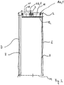
- Fig. 1 shows a schematic representation of a perspective view of a cage for a roller bearing according to an embodiment.
- a cage for a roller bearing (not shown) comprises a first side ring 2 and a second side ring 3.
- the cage 1 also comprises a plurality of webs 4.
- the webs 4 connect the side rings 2 and 3. This creates a plurality of pockets 5 for receiving formed by rolling elements, not shown.
- the webs 4 are arranged on a different diameter than a pitch circle diameter of the roller bearing.
- the cage 1 comprises at least one guide surface 7.
- the guide surface 7 is designed to radially guide the cage 1 on a running surface, not shown, of the roller bearing, not shown.
- the cage 1 also has at least one recess 8 in the guide surface 7.
- the recess 8 does not penetrate the cage 1 in the radial direction. In the axial direction, the recess 8 extends at least in sections from an axial end edge 9 over a width B of the cage 1, so that a flow of lubricant along the recess 8 onto the pockets 5 is possible.
- the recess 8 extends in the embodiment of FIG Fig. 1 completely over a width of the cage 1.
- the recess 8 has a width b which corresponds to a width b of the web 4.
- a width b of the web 4 is an extension of the web in a circumferential direction.
- the recess 8 has a width K in each case.
- the width K of the recess 8 in the area of the side rings 2 and 3 is greater than a width b of the web 4.
- the cage 1 of the embodiment of FIG Figure 1 is designed to be guided on a raceway of an outer ring, not shown, of a roller bearing.
- the guide surface 7 rests against the raceway of the outer ring.
- the recess 8 has a depth t.
- a depth t of the recess 8 is an extension of the recess in a radial direction.
- the depth t is designed to be less than a thickness d of at least one of the side rings 2 or 3.
- the thickness d is an extension of one of the side rings 2 or 3 in a radial direction.
- the side rings 2 and 3 are each designed so that their radially inwardly directed surface lies on a common diameter.
- the webs 4 have in the embodiment of Fig. 1 a substantially trapezoidal cross-section.
- a radially inwardly facing surface 10 of the web 4 has a smaller width u than the width b of the web 4. This could make it possible that the webs 4 have a high stability.
- the rolling elements are only spaced from one another so far that they just no longer touch one another.
- the webs 4 can have a triangular shape and protrude almost as far as a center point of the rolling bodies.
- the side rings 2 and 3 extend radially inwards to a lesser extent than the webs 4.
- Fig. 2 shows a schematic cross-sectional representation of a roller and cage assembly with two cages according to the embodiment.
- a plurality of rolling elements 11 can be arranged in two rows on a mounting sleeve 12 in the case of a roller ring 13.
- Each row of rolling elements 11 is guided with a cage 1a and 1b according to the exemplary embodiment.
- the cages 1a and 1b are arranged next to one another in the axial direction.
- cages can also be used individually. A roller and cage assembly can then only have a number of rolling elements.
- the rolling elements 11 run on an inner running surface with a diameter f.
- the diameter f can be in a range between 30 mm and 40 mm.
- the cage 1a has an outer diameter E.
- the outside diameter E is approximately 54.75 mm.
- the rolling elements 11 run on an outer running surface with a diameter D.
- the diameter D is approximately 55 mm.
- the cage 1 thus has a smaller diameter than a running surface on which it is guided.
- the difference between the outer diameter of the cage E and the diameter of the outer running surface D is provided in order to enable the cage to grow with an increase in temperature.
- the cage has an inside diameter F between 40 mm and 50 mm.
- an inner diameter of the cage, an outer diameter of the cage and / or the raceways can have a diameter which lies in a range of values.
- the range of values has a start value and an end value.
- the initial value and / or the Final value 5 mm, 10 mm, 20 mm, 30 mm, 40 mm, 50 mm, 55 mm, 60 mm, 70 mm 80 mm, 100 mm, 150 mm, 200 mm and / or 250 mm.
- the cage 1 is a distributor cage guided on the outer ring raceway, in which the rollers or rolling elements are held outside in the cage 1.
- the cage 1 according to the embodiment of FIG Fig. 1 and 2 is suitable for a cylindrical roller bearing or a roller cage.
- the rolling elements 11 are cylindrical rollers.
- the cage 1 can be used, for example, in bearings of small mobile planetary gears that are produced in large numbers. Due to the recesses on the diameter and the recessed side rings 2 and 3 in comparison to the cage bars 4, sufficient free space for a sufficient oil flow can be made possible in some exemplary embodiments, even if the bearing has a small diameter and the space is limited as a result.
- the cage 1 is a plastic cage guided on the outer ring raceway.
- the cage 1 is not self-retaining. This means that an inner diameter of the cage web 4 is greater than the pitch circle diameter of the roller bearing. In this way, the maximum number of rolling elements can be achieved. The maximum possible number of rolling elements can therefore be made possible by a special cage design. Due to the recesses on the outer diameter of the side rings or cage side rings 2 and 3 and an enlarged inner diameter of the side rings 2 and 3, a sufficient or even optimal oil flow can be made possible in some exemplary embodiments. Since the cage 1 keeps the rolling elements at a distance, a risk of smearing due to roller-to-roller contact can also be avoided. A high-capacity cylindrical roller bearing cage made of a plastic material could therefore be provided. These can be produced, for example, by an injection molding process.
- Cages according to the exemplary embodiments can be used in all possible applications.
- cages are suitable for roller and cage assemblies or roller bearings with small roller and pitch circle diameters. In this way, for example, inexpensive and technically feasible solutions could be provided.
- a special application of the cage can be as an outer ring raceway-guided cage for a cylindrical roller bearing.
- the cage can be used in all possible rolling bearings. Rolling bearings with the cage can be used, for example, for planetary gear bearings. Further applications can be all possible applications in vehicles (e.g. trucks, passenger cars), machine tools or work machines.
- the cages are also suitable for use in small roller and cage assemblies or bearings with a cage diameter of up to approx. 250 mm. Another area of application can be in transmissions of any kind.
Description
Ausführungsbeispiele beziehen sich auf einen Käfig für ein Wälzlager und ein Wälzlager mit dem Käfig.Embodiments relate to a cage for a roller bearing and a roller bearing with the cage.
Als Wälzlager mit einer hohen Tragzahl werden sogenannte vollrollige Rollenkränze oder Rollenlager verwendet. Vollrollige Wälzlager ergeben rechnerisch die höchste Tragzahl. Bei einem vollrolligen Lager sind so viele Wälzkörper in dem Wälzlager angeordnet, dass die Summe der Einzeldurchmesser der Wälzkörper fast einen Teilkreisdurchmesser des Wälzlagers ergibt. Dazu wird bei vielen konventionellen vollrolligen Wälzlagern kein Käfig verwendet. Bei vollrolligen Lagern berühren sich die Rollen. Es könnte also eine Reibung zwischen den Rollen auftreten. Die Gefahr einer sog. Anschmierungen der Rollen könnte sich erhöhen. Dies kann u.U. zu einer Verkürzung der Lebensdauer des Wälzlagers führen. Solche vollrolligen Wälzlager oder Rollenkränze werden beispielsweise zur Lagerung der Planeten in einem mobilen Planetenradgetriebe eingesetzt.So-called full complement roller and cage assemblies or roller bearings are used as roller bearings with a high load rating. Mathematically, full complement rolling bearings result in the highest load rating. In a full complement bearing, so many rolling elements are arranged in the rolling bearing that the sum of the individual diameters of the rolling elements results in almost a pitch circle diameter of the rolling bearing. Many conventional full complement rolling bearings do not use a cage for this purpose. In the case of full complement bearings, the rollers touch each other. So there could be some friction between the rollers. The risk of so-called smearings on the rollers could increase. This can lead to a reduction in the service life of the rolling bearing. Such full complement roller bearings or roller and cage assemblies are used, for example, to support the planets in a mobile planetary gear unit.
Für andere Anwendungen im Bereich der Windkraftgetriebe werden sog. High-Capacity-Zylinderrollenlager (von engl.: "hohe dynamische Tragfähigkeit") eingesetzt. Diese können ebenfalls vollrollig ausgebildet bzw. eine maximale Rollenzahl aufweisen. Die Wälzkörper sind aber bei diesen konventionellem Zylinderrollenlager durch einen schulter- oder laufbahngeführten Käfig auf einem minimalen Abstand gehalten. Dadurch könnte ein Anschmierungsrisiko durch einen direkten Rolle-Rolle-Kontakt vermieden werden. Für große Zylinderrollenlager, wie sie beispielsweise in Windkraftgetrieben und großen Planetenradgetrieben zum Einsatz kommen, werden dazu Stahlblech- oder Messingmassivkäfige verwendet.So-called high-capacity cylindrical roller bearings (from English: "high dynamic load capacity") are used for other applications in the field of wind power gearboxes. These can also have a full complement or have a maximum number of rollers. In these conventional cylindrical roller bearings, however, the rolling elements are kept at a minimum distance by a shoulder or raceway-guided cage. In this way, the risk of smearing due to direct roller-roller contact could be avoided. Sheet steel or solid brass cages are used for large cylindrical roller bearings, such as those used in wind power gears and large planetary gears.
Für kleine Lager sind die konventionellen Lösungen zum einen unwirtschaftlich. Zum anderen führt das Verkleinern konventioneller vollrolliger Lager mit einem laufbahngeführten Käfig, wie sie in großen Dimensionen im Bereich der Windkraftgetriebe eingesetzt werden dazu, dass kein ausreichender Öl- oder Schmiermittelfluss mehr möglich ist. Dieser Effekt ist unerwünscht.On the one hand, the conventional solutions are uneconomical for small warehouses. On the other hand, the reduction in size of conventional full complement bearings with a raceway-guided cage, as used in large dimensions in the field of wind power gearboxes, means that an adequate flow of oil or lubricant is no longer possible. This effect is undesirable.
Es besteht daher ein Bedarf daran, einen Kompromiss zwischen einer Erhöhung der Tragfähigkeit eines Wälzlagers, dem Vermeiden dass Wälzköper aneinander reiben und einer ausreichenden Schmiermittelzufuhr zu verbessern. Diesem Bedarf tragen die unabhängigen Ansprüche 1 und 8 Rechnung.There is therefore a need to find a compromise between increasing the load-bearing capacity of a rolling bearing, preventing rolling elements from rubbing against one another, and improving an adequate supply of lubricant. The independent claims 1 and 8 take this need into account.
Ausführungsbeispiele betreffen einen Käfig für ein Wälzlager, wobei das Wälzlager ein Zylinderrollenlager ist. Der Käfig umfasst einen ersten und einen zweiten in eine Umfangsrichtung angeordneten Seitenring. Ferner weist der Käfig eine Mehrzahl von Stegen auf. Die Stege verbinden die Seitenringe. Dabei wird eine Mehrzahl von Taschen zur Aufnahme von Wälzkörpern ausgebildet. Die Stege sind auf einem anderen Durchmesser als einem Teilkreisdurchmesser des Wälzlagers angeordnet. Ferner weist der Käfig zumindest eine Führungsfläche auf. Die Führungsfläche ist ausgebildet, um den Käfig an einer Lauffläche des Wälzlagers radial zu führen. Der Käfig ist nicht selbsthaltend, wobei bei einem außenringgeführten Käfig ein Innendurchmesser des Stegs größer ist als der Teilkreisdurchmesser des Wälzlagers und bei einem innenringgeführten Käfig ein Außendurchmesser des Stegs kleiner ist als der Teilkreisdurchmesser des Wälzlagers. Der Käfig umfasst auch eine Ausnehmung in der Führungsfläche. Die Ausnehmung durchdringt den Käfig in radialer Richtung nicht. In axialer Richtung erstreckt sich die Ausnehmung zumindest abschnittsweise von einer axialen Stirnkante des Seitenrings über eine Breite des Käfigs, sodass ein Schmiermittelfluss entlang der Ausnehmung auf die Taschen möglich ist. Dabei sind der Käfig und ein Material des Käfigs so ausgebildet, dass sich die Wälzkörper in allen normalen Betriebszuständen gerade nicht berühren. Ferner ist die zumindest eine Ausnehmung im Bereich der Stege angeordnet, und außerhalb der zumindest einen Ausnehmung ist eine Oberfläche der Seitenringe als Führungsfläche ausgebildet. Des Weiteren weist die Ausnehmung in einem Bereich des Stegs eine Breite auf, die einer Breite des Stegs entspricht.Embodiments relate to a cage for a roller bearing, the roller bearing being a cylindrical roller bearing. The cage comprises a first and a second side ring arranged in a circumferential direction. The cage also has a plurality of webs. The bars connect the side rings. In this case, a plurality of pockets for receiving rolling elements is formed. The webs are arranged on a different diameter than a pitch circle diameter of the roller bearing. Furthermore, the cage has at least one guide surface. The guide surface is designed to radially guide the cage on a running surface of the roller bearing. The cage is not self-retaining, with an inner diameter of the web being larger than the pitch circle diameter of the roller bearing in the case of a cage guided on the outer ring and an outer diameter in the case of a cage guided in the inner ring of the web is smaller than the pitch diameter of the rolling bearing. The cage also includes a recess in the guide surface. The recess does not penetrate the cage in the radial direction. In the axial direction, the recess extends at least in sections from an axial end edge of the side ring over a width of the cage, so that a flow of lubricant along the recess onto the pockets is possible. The cage and a material of the cage are designed in such a way that the rolling elements do not touch each other in all normal operating states. Furthermore, the at least one recess is arranged in the region of the webs, and outside the at least one recess a surface of the side rings is designed as a guide surface. Furthermore, the recess has a width in a region of the web which corresponds to a width of the web.
Dadurch, dass der Käfig an der Führungsfläche eine Ausnehmung aufweist, kann bei manchen Ausführungsbeispielen ermöglicht werden, dass die Wälzkörper in einem Wälzlager voneinander beabstandet positioniert werden können und trotzdem ein ausreichender Ölfluss oder Schmiermittelfluss an den Laufflächen der Wälzkörper und an den Laufflächen des Außen- oder Innenrings ermöglicht werden kann. Dies könnte dann der Fall sein, wenn das Schmiermittel in axialer Richtung seitlich zwischen den Innen- und Außenring eingebracht wird. In diesen Fällen kann das Schmiermittel von der axialen Stirnkante des Seitenrings entlang der Ausnehmung fließen. Wenn sich die Wälzkörper und der Käfig in Umfangsrichtung bewegen, wird das Schmiermittel entlang den Laufflächen transportiert.Because the cage has a recess on the guide surface, it can be made possible in some exemplary embodiments that the rolling elements can be positioned at a distance from one another in a rolling bearing and still have a sufficient flow of oil or lubricant on the running surfaces of the rolling elements and on the running surfaces of the outer or Inner ring can be made possible. This could be the case if the lubricant is introduced laterally in the axial direction between the inner and outer rings. In these cases, the lubricant can flow from the axial end edge of the side ring along the recess. When the rolling elements and the cage move in the circumferential direction, the lubricant is transported along the running surfaces.
Ein Teilkreisdurchmesser ist dabei ein Durchmesser, auf dem die Mittelpunkte der Wälzkörper angeordnet sind. Beispielsweise kann die Mehrzahl der Stege in radialer Richtung, zumindest entlang einer axialen Ausdehnung des Wälzkörpers, vollständig außerhalb des Teilkreises angeordnet sein. Die Stege können eventuell auch entlang ihrer gesamten axialen Ausdehnung vollständig außerhalb des Teilkreise angeordnet sein.A pitch circle diameter is a diameter on which the center points of the rolling elements are arranged. For example, the majority of the webs can be arranged completely outside of the pitch circle in the radial direction, at least along an axial extension of the rolling body. The webs can possibly also be arranged completely outside of the pitch circle along their entire axial extent.
Bei einigen weiteren Ausführungsbeispielen sind die Stege parallel zueinander und parallel zu einer axialen Richtung des Käfigs angeordnet. Beispielsweise kann der Käfig zum Führen der Wälzkörper in einem Zylinderrollenlager eingesetzt werden.In some further exemplary embodiments, the webs are arranged parallel to one another and parallel to an axial direction of the cage. For example, the cage can be used to guide the rolling elements in a cylindrical roller bearing.
Bei einigen weiteren Ausführungsbeispielen kann das Wälzlager ein Rollenkranz sein.In some further exemplary embodiments, the roller bearing can be a roller ring.
Bei der axialen Stirnkante des Seitenrings handelt es sich um eine Fläche, die in eine axiale Richtung des Käfigs gerichtet ist. Beispielsweise kann die Stirnkante auch um einen Winkel gegenüber der axialen Richtung geneigt sein. Der Winkel liegt in einem Wertebereich. Der Wertebereich weist einen Anfangswert und einen Endwert auf. Beispielsweise können der Anfangswert und/oder der Endwert 0°, 1°, 2°, 5°oder 10° betragen. Dadurch kann bei manchen Ausführungsbeispielen ermöglicht werden, dass bei einer Rotation des Käfigs das Schmiermedium in ein Inneres des Lagers geleitet wird. Dies kann beispielsweise durch eine Pumpwirkung bzw. Fliehkräfte bewirkt werden.The axial end edge of the side ring is a surface that is directed in an axial direction of the cage. For example, the front edge can also be inclined at an angle with respect to the axial direction. The angle lies in a range of values. The range of values has a start value and an end value. For example, the start value and / or the end value can be 0 °, 1 °, 2 °, 5 ° or 10 °. In some exemplary embodiments, this makes it possible for the lubricating medium to be guided into an interior of the bearing when the cage rotates. This can be brought about, for example, by a pumping action or centrifugal forces.
Bei einigen weiteren Ausführungsbeispielen erstreckt sich die Ausnehmung vollständig über eine Breite des Käfigs. Eine Breite des Käfigs ist eine Ausdehnung des Käfigs in eine axiale Richtung. So kann bei manchen Ausführungsbeispielen ermöglicht werden, dass das Schmiermittel nur von einer Seite in das Wälzlager eingebracht werden muss und entlang der Ausnehmung, die sich über die gesamte Breite des Käfigs erstreckt, das Wälzlager entlang seiner gesamten Breite schmiert. Beispielsweise kann die Ausnehmung nur an den Stegen bzw. in Umfangsrichtung überlappend mit den Stegen und an den Seitenringen nur in einem Bereich, der in axialer Richtung an den Steg anschließt, angeordnet sein. Außerhalb der Ausnehmung kann eine Oberfläche der Seitenringe, die zu der Lauffläche gewandt ist, vollständig als Führungsfläche ausgebildet sein. Dazu kann die Oberfläche der Seitenringe, die der Lauffläche zugewandt ist, außerhalb der Ausnehmung frei von Vertiefungen sein und/oder einen einheitlichen Durchmesser aufweisen.In some further exemplary embodiments, the recess extends completely over a width of the cage. A width of the cage is an extension of the cage in an axial direction. In some exemplary embodiments, it can be made possible that the lubricant only has to be introduced into the roller bearing from one side and lubricates the roller bearing along its entire width along the recess, which extends over the entire width of the cage. For example, the recess can only be arranged on the webs or overlapping in the circumferential direction with the webs and on the side rings only in an area which adjoins the web in the axial direction. Outside the recess, a surface of the side rings that faces the running surface can be designed entirely as a guide surface. For this purpose, the surface of the side rings facing the running surface can be free of depressions outside the recess and / or have a uniform diameter.
Bei einigen weiteren Ausführungsbeispielen kann die Ausnehmung durch eine Rippe unterbrochen sein. Die Rippe kann den gleichen Durchmesser wie die Seitenringe aufweisen. So kann bei manchen Ausführungsbeispielen beispielsweise ermöglicht werden, dass die Rippe zu einer zusätzlichen Führung auf der Laufbahn genutzt werden kann. Beispielsweise kann in diesen Fällen das Schmiermedium bzw. das Schmiermittel von zwei Seiten eingebracht werden.In some further exemplary embodiments, the recess can be interrupted by a rib. The rib can have the same diameter as the side rings. In some exemplary embodiments, for example, it can be made possible that the rib can be used for additional guidance on the track. For example, in these cases the lubricant or lubricant can be introduced from two sides.
Bei einigen weiteren Ausführungsbeispielen ist der Käfig ausgebildet, um an einer Innenlaufbahn des Zylinderrollenlagers geführt zu werden. Dadurch weist der Käfig einen kleineren Durchmesser auf als ein außenlaufbahngeführter Käfig. Auch ein Gewicht des Käfigs könnte dann reduziert sein.In some further exemplary embodiments, the cage is designed to be guided on an inner raceway of the cylindrical roller bearing. As a result, the cage has a smaller diameter than a cage guided on the outside of the raceway. The weight of the cage could then also be reduced.
Bei einigen weiteren Ausführungsbeispielen ist die Ausnehmung in radialer Richtung zumindest abschnittsweise innerhalb des Stegs angeordnet. Dadurch kann bei manchen Ausführungsbeispielen eine ausreichende Schmierung an der Innenringlaufbahn ermöglicht werden.In some further exemplary embodiments, the recess is arranged at least in sections in the radial direction within the web. As a result, in some exemplary embodiments, sufficient lubrication on the inner ring raceway can be made possible.
Bei einigen weiteren Ausführungsbeispielen ist der Käfig ausgebildet, um an einer Außenlaufbahn des Zylinderrollenlagers geführt zu werden. Dadurch könnte der Käfig einen größeren Durchmesser aufweisen als ein innenlaufbahngeführter Käfig. Eine Stabilität des Käfigs könnte so erhöht werden und/oder auch die Anzahl der Wälzkörper im Vergleich zu einem Innenringlaufbahn geführten Käfig bei gleichem Teilkreis und gleichen Wälzkörperabmessungen.In some further exemplary embodiments, the cage is designed to be guided on an outer raceway of the cylindrical roller bearing. As a result, the cage could have a larger diameter than a cage guided on the inside of the track. A stability of the cage could thus be increased and / or the number of rolling elements could be increased compared to a cage guided by an inner ring raceway with the same pitch circle and the same rolling element dimensions.
Ferner weist die Ausnehmung in einem Bereich des Stegs eine Breite auf, die einer Breite des Stegs entspricht. Dabei ist die Breite der Ausnehmung eine Ausdehnung der Ausnehmung in eine Umfangsrichtung. Analog ist die Breite des Stegs eine Ausdehnung des Stegs in eine Umfangsrichtung des Käfigs. So kann bei manchen Ausführungsbeispielen ermöglicht werden, dass das Schmiermittel von dem Steg direkt in die Tasche laufen kann..Furthermore, the recess has a width in a region of the web which corresponds to a width of the web. The width of the recess is an extension of the recess in a circumferential direction. Analogously, the width of the web is an extension of the web in a circumferential direction of the cage. In some exemplary embodiments, it can thus be made possible that the lubricant can run from the web directly into the pocket.
Bei einigen weiteren Ausführungsbeispielen kann die Ausnehmung in einer Mehrzahl von Stegen angeordnet sein. Beispielsweise kann die Ausnehmung in jedem der Stege oder auch nur in jedem zweiten, jedem dritten, jedem vierten oder jedem fünftem, etc. Steg angeordnet sein. Dadurch, dass beispielsweise nicht alle Stege die Ausnehmung aufweisen, kann bei manchen Ausführungsbeispielen eine Stabilität des Käfigs erhöht sein und trotzdem noch ein ausreichender Schmiermittelfluss ermöglicht werden.In some further exemplary embodiments, the recess can be arranged in a plurality of webs. For example, the recess can be arranged in each of the webs or only in every second, every third, every fourth or every fifth, etc. web. Because, for example, not all webs have the recess, the stability of the cage can be increased in some exemplary embodiments and a sufficient flow of lubricant can still be made possible.
Ergänzend oder alternativ kann die Ausnehmung auch in dem Bereich des zumindest einen Seitenrings eine Breite aufweisen, die der Breite der Ausnehmung in dem Bereich des Stegs entspricht.In addition or as an alternative, the recess can also have a width in the region of the at least one side ring which corresponds to the width of the recess in the region of the web.
Bei einigen weiteren Ausführungsbeispielen weist der Käfig einen Durchmesser auf, der in einem Wertebereich liegt. Der Wertebereich weist einen Anfangs- und einen Endwert auf. Anfangs- und Endwerte des Wertebereichs können 10 mm, 20 mm, 30 mm, 40 mm, 50 mm, 55 mm, 60 mm, 70 mm, 80 mm, 100 mm, 150 mm, 200 mm und/oder 250 mm sein. So kann bei manchen Ausführungsbeispielen ein Käfig für ein Lager mit einem relativ kleinen Durchmesser hier bereitgestellt werden. Beispielsweise können solche Lager zum drehbaren Lagern von kleinen mobilen Planetengetrieben eingesetzt werden. Beispielsweise könnte so der Schmiermittelfluss auch in vollrolligen Lagern mit kleinen Durchmessern ermöglicht werden.In some further exemplary embodiments, the cage has a diameter which lies in a range of values. The range of values has a start and an end value. The start and end values of the value range can be 10 mm, 20 mm, 30 mm, 40 mm, 50 mm, 55 mm, 60 mm, 70 mm, 80 mm, 100 mm, 150 mm, 200 mm and / or 250 mm. In some exemplary embodiments, a cage for a bearing with a relative small diameter can be provided here. For example, such bearings can be used for the rotatable mounting of small mobile planetary gears. For example, the flow of lubricant could also be made possible in full complement bearings with small diameters.
Bei einigen weiteren Ausführungsbeispielen ist der Käfig aus wenigstens einem Kunststoffspritzgussteil aufgebaut. So kann in manchen Fällen die Herstellung des Käfigs vereinfacht sein. Ferner kann der Käfig bei manchen Ausführungsbeispielen aus einer Mehrzahl von Käfigsegmenten ausgebildet sein. Mit anderen Worten ausgedrückt, kann der Käfig segmentiert ausgebildet sein. Dadurch könnte beispielsweise eine Montierbarkeit des Käfigs vereinfacht werden.In some further exemplary embodiments, the cage is constructed from at least one plastic injection-molded part. The manufacture of the cage can thus be simplified in some cases. Furthermore, in some exemplary embodiments, the cage can be formed from a plurality of cage segments. In other words, the cage can be segmented. This could, for example, simplify the assembly of the cage.
Bei einigen weiteren Ausführungsbeispielen weist die Ausnehmung eine Tiefe auf, die geringer ist als eine Dicke des Seitenrings. Dabei ist eine Tiefe der Ausnehmung eine Ausdehnung der Ausnehmung in eine radiale Richtung. Analog ist eine Dicke des Seitenrings eine Ausdehnung des Seitenrings in eine radiale Richtung. Beispielsweise können die Seitenringe unterschiedliche Dicken aufweisen. Bei diesen Ausführungsbeispielen kann die Ausnehmung eine Tiefe aufweisen, die geringer ist als eine Dicke des Seitenrings mit der geringeren Dicke. Beispielsweise kann die Ausnehmung eine Tiefe aufweisen, die maximal 50% der Dicke des Seitenrings entspricht. So kann bei manchen Ausführungsbeispielen ein Kompromiss zwischen einer Stabilität des Seitenrings und einer ausreichend großen Ausnehmung für einen benötigten Schmiermittelfluss verbessert sein.In some further exemplary embodiments, the recess has a depth that is less than a thickness of the side ring. A depth of the recess is an extension of the recess in a radial direction. Analogously, a thickness of the side ring is an extension of the side ring in a radial direction. For example, the side rings can have different thicknesses. In these exemplary embodiments, the recess can have a depth which is less than a thickness of the side ring with the smaller thickness. For example, the recess can have a depth that corresponds to a maximum of 50% of the thickness of the side ring. Thus, in some exemplary embodiments, a compromise between a stability of the side ring and a sufficiently large recess for a required flow of lubricant can be improved.
Bei einigen weiteren Ausführungsbeispielen weist zumindest einer der Seitenringe einen durchgängigen Materialbereich auf, der auf einem Durchmesser liegt. So kann bei manchen Ausführungsbeispielen der Käfig eine ausreichende Stabilität erhalten. Mit anderen Worten ausgedrückt, kann beispielsweise eine nach radial innen oder eine nach radial außen zeigende Fläche des Seitenrings durchgehend den gleichen Durchmesser aufweisen.In some further exemplary embodiments, at least one of the side rings has a continuous material region that lies on a diameter. In some exemplary embodiments, the cage can thus be given sufficient stability. In other words, for example, a radially inward or radially outward facing surface of the side ring can have the same diameter throughout.
Bei einigen weiteren Ausführungsbeispielen erstrecken sich die Stege ausgehend von den Seitenringen in radialer Richtung weg von der Führungsfläche, weiter in eine radiale Richtung von den Seitenringen. So kann bei manchen Ausführungsbeispielen eine Stabilität des Käfigs erhöht sein. Dies kann ggf. möglich sein, weil die Stege einen möglichst großen Querschnitt aufweisen. Bei manchen Ausführungsbeispielen erstrecken sich die Stege nur soweit in die radiale Richtung, dass sie die Wälzlager nicht unnötig weit voneinander beabstanden.In some further exemplary embodiments, the webs, starting from the side rings, extend in the radial direction away from the guide surface, and further in a radial direction from the side rings. In some exemplary embodiments, the stability of the cage can thus be increased. This may possibly be possible because the webs have the largest possible cross-section. In some exemplary embodiments, the webs only extend so far in the radial direction that the rolling bearings are not spaced unnecessarily far from one another.
Ferner werden die Stege bei einigen weiteren Ausführungsbeispielen an ihren zu dem Wälzkörpermittelpunkt zeigenden Enden immer dünner. Dadurch könnte ermöglicht werden, dass ein Abstand zwischen den Wälzkörpern so klein wie möglich gehalten werden kann. Beispielsweise kann der Abstand so gewählt sein, dass sich die Wälzkörper gerade noch nicht berühren. Aus fertigungstechnischen Gründen erstrecken sich die Stege bei manchen Ausführungsbeispielen nur so weit bis zu dem Mittelpunkt der Wälzkörper bzw. weisen eine entsprechende Wandstärke auf, solange diese gut zu entformen bzw. herzustellen ist.Furthermore, in some further exemplary embodiments, the webs become thinner and thinner at their ends pointing towards the rolling element center point. This could enable a distance between the rolling elements to be kept as small as possible. For example, the distance can be selected so that the rolling elements just do not touch one another. For reasons of manufacturing technology, the webs in some exemplary embodiments extend only so far as far as the center point of the rolling elements or have a corresponding wall thickness as long as this can be easily demolded or manufactured.
Dabei sind der Käfig und ein Material des Käfigs so ausgebildet, dass sich die Wälzkörper in allen normalen Betriebszuständen gerade nicht berühren. So kann ermöglicht werden, dass so viele Wälzkörper in dem Wälzlager aufgenommen werden können, dass die Summe der einzelnen Durchmesser der Wälzkörper fast einem Durchmesser entspricht, auf dem die Mittelpunkte der Wälzlager angeordnet sind. Beispielsweise kann ein minimaler Abstand zwischen zwei direkt nebeneinander angeordneten Wälzkörpern größer gleich 1% des Wälzkörperdurchmessers sein. Mit anderen Worten ausgedrückt, ist der Käfig ausgebildet, um die Wälzkörper in einem vollrolligen Lager so voneinander zu beabstanden, dass sie nicht aneinander anschmieren oder reiben. Normale Betriebszustände können dabei Betriebszustände mit unterschiedlichen Temperaturen sein, die beispielsweise eine Ausdehnung des Käfigs bewirken könnten. Ferner können normale Betriebszustände auch unterschiedliche Kräfte umfassen, die ggf. zu einer ungleichmäßigen Belastung des Käfigs und/oder des Lagers führen könnten. Mit anderen Worten ausgedrückt, sind der Käfig und das Material des Käfigs bei manchen Ausführungsbeispielen hinsichtlich ihrer Deformationseigenschaften so ausgebildet, dass sie die Wälzkörper in den beschriebenen Abständen halten können.The cage and a material of the cage are designed in such a way that the rolling elements do not touch each other in all normal operating states. It can thus be made possible that so many rolling elements can be accommodated in the rolling bearing that the sum of the individual diameters of the rolling elements almost corresponds to a diameter on which the centers of the rolling bearings are arranged. For example, a minimum distance between two rolling elements arranged directly next to one another can be greater than or equal to 1% of the rolling element diameter. In other words, the cage is designed to space the rolling elements in a full complement bearing from one another in such a way that they do not smear or rub against one another. Normal operating states can be operating states with different temperatures, which could, for example, cause the cage to expand. Furthermore, normal operating states can also include different forces which could possibly lead to uneven loading of the cage and / or the bearing. In other words, in some exemplary embodiments, the cage and the material of the cage are designed with regard to their deformation properties in such a way that they can hold the rolling elements at the distances described.
Einige Ausführungsbeispiele betreffen ein Zylinderrollenlager mit einem Käfig nach zumindest einem der beschriebenen Ausführungsbeispiele. Der Käfig ist an einer der Laufbahnen des Rollenlagers geführt. Ferner ist der Käfig so ausgebildet, um eine maximale Anzahl an Wälzkörpern aufzunehmen. So könnte beispielsweise ein Rollenlager mit einer hohen Tragzahl und einer erhöhten Lebensdauer bereitgestellt werden. Dies könnte möglich sein, weil bei manchen Ausführungsbeispielen verhindert werden kann, dass die Wälzkörper sich gegenseitig berühren. Mit maximaler Anzahl an Wälzkörpern ist dabei die Menge an Wälzkörpern gemeint, die in dem Wälzlager untergebracht werden können, ohne sich gegenseitig zu berühren. Das heißt, es könnten so viele Wälzkörper in dem Lager angeordnet sein, dass die Summe der Durchmesser der Wälzkörper fast einem Durchmesser, auf dem die Mittelpunkte der Wälzkörper laufen, entspricht. Die Summe kann etwas geringer sein, um so viel Abstand vorzusehen, dass sich die Wälzkörper gerade nicht berühren. Die Laufbahn kann sich beispielweise an einem bordfreien Bauteil, beispielsweise einem Lagerring oder einem Gehäuse oder in einer Bohrung befinden. Beispielsweise kann der Käfig an einer radial außenliegenden Lauffläche geführt sein.
Weitere vorteilhafte Ausgestaltungen werden nachfolgendend anhand von in den Zeichnungen dargestellten Ausführungsbeispielen, auf welche Ausführungsbeispiele jedoch nicht beschränkt sind, näher beschrieben.Some exemplary embodiments relate to a cylindrical roller bearing with a cage according to at least one of the exemplary embodiments described. The cage is guided on one of the raceways of the roller bearing. Furthermore, the cage is designed to accommodate a maximum number of rolling elements. For example, a roller bearing with a high load rating and an increased service life could be provided. This could be possible be because, in some exemplary embodiments, the rolling elements can be prevented from touching one another. The maximum number of rolling elements here means the amount of rolling elements that can be accommodated in the rolling bearing without touching one another. This means that so many rolling elements could be arranged in the bearing that the sum of the diameters of the rolling elements almost corresponds to a diameter on which the centers of the rolling elements run. The sum can be a little less in order to provide enough space that the rolling elements do not just touch each other. The raceway can be located, for example, on a rim-free component, for example a bearing ring or a housing, or in a bore. For example, the cage can be guided on a radially outer running surface.
Further advantageous configurations are described in more detail below with reference to the exemplary embodiments shown in the drawings, to which exemplary embodiments are, however, not limited.
So zeigen die Figuren schematisch die nachfolgenden Ansichten.
-
Fig. 1 zeigt eine schematische Darstellung einer perspektivischen Ansicht eines Käfigs für ein Wälzlager gemäß einem Ausführungsbeispiel; und -
Fig. 2 zeigt eine schematische Querschnittsdarstellung eines Rollenkranzes gemäß einem weiteren Ausführungsbeispiel.
-
Fig. 1 shows a schematic representation of a perspective view of a cage for a roller bearing according to an embodiment; and -
Fig. 2 shows a schematic cross-sectional illustration of a roller and cage assembly according to a further exemplary embodiment.
Bei der nachfolgenden Beschreibung der beigefügten Darstellungen bezeichnen gleiche Bezugszeichen gleiche oder vergleichbare Komponenten. Ferner werden zusammenfassende Bezugszeichen für Komponenten und Objekte verwendet, die mehrfach in einem Ausführungsbeispiel oder in einer Darstellung auftreten, jedoch hinsichtlich eines oder mehrerer Merkmale gemeinsam beschrieben werden. Komponenten oder Objekte, die mit gleichen oder zusammenfassenden Bezugszeichen beschrieben werden, können hinsichtlich einzelner, mehrerer oder aller Merkmale, beispielsweise ihrer Dimensionierungen, gleich, jedoch gegebenenfalls auch unterschiedlich ausgeführt sein, sofern sich aus der Beschreibung nicht etwas anderes explizit oder implizit ergibt.In the following description of the attached illustrations, the same reference symbols designate the same or comparable components. Furthermore, summarizing reference symbols are used for components and objects that occur several times in an exemplary embodiment or in a representation, but are described together with regard to one or more features. Components or objects that are described with the same or summarizing reference symbols can be identical with regard to individual, several or all features, for example their dimensions, but possibly also different, unless the description explicitly or implicitly results in something else.
Wie in
Die Ausnehmung 8 erstreckt sich bei dem Ausführungsbeispiel der
In einem Bereich der Seitenringe 2 und 3 weist die Ausnehmung 8 jeweils eine Breite K auf. Die Breite K der Ausnehmung 8 in dem Bereich der Seitenringe 2 und 3 ist größer als eine Breite b des Stegs 4. Der Käfig 1 des Ausführungsbeispiels der
Die Stege 4 weisen bei dem Ausführungsbeispiel der
Wie in
Bei einigen weiteren Ausführungsbeispielen können Käfige auch einzeln eingesetzt werden. Ein Rollenkranz kann dann nur eine Reihe von Wälzkörpern aufweisen.In some further exemplary embodiments, cages can also be used individually. A roller and cage assembly can then only have a number of rolling elements.
Bei dem Ausführungsbeispiel laufen die Wälzkörper 11 auf einer Innenlauffläche mit einem Durchmesser f. Der Durchmesser f kann in einem Bereich zwischen 30 mm und 40 mm liegen. Der Käfig 1a weist einen Außendurchmesser E auf. Der Außendurchmesser E beträgt etwa 54,75 mm. Die Wälzkörper 11 laufen auf einer Außenlauffläche mit einem Durchmesser D. Der Durchmesser D ist etwa 55 mm. Der Käfig 1 weist also einen geringeren Durchmesser auf, als eine Lauffläche, an der er geführt ist. Der Unterschied zwischen dem Außendurchmesser des Käfigs E und dem Durchmesser der Außenlauffläche D wird vorgesehen, um ein Wachsen des Käfigs bei einer Temperaturerhöhung zu ermöglichen. Der Käfig weist einen Innendurchmesser F zwischen 40 mm und 50 mm auf.In the exemplary embodiment, the rolling
Bei einigen weiteren, nicht dargestellten Ausführungsbeispielen können ein Innendurchmesser des Käfigs, ein Außendurchmesser des Käfigs und/oder die Laufbahnen einen Durchmesser aufweisen, der in einem Wertebereich liegt. Der Wertebereich weist einen Anfangswert und einen Endwert auf. Beispielsweise kann der Anfangswert und/oder der Endwert sein: 5 mm, 10 mm, 20 mm, 30 mm, 40 mm, 50 mm, 55 mm, 60 mm, 70 mm 80 mm, 100 mm, 150 mm, 200 mm und/oder 250mm.In some further exemplary embodiments, not shown, an inner diameter of the cage, an outer diameter of the cage and / or the raceways can have a diameter which lies in a range of values. The range of values has a start value and an end value. For example, the initial value and / or the Final value: 5 mm, 10 mm, 20 mm, 30 mm, 40 mm, 50 mm, 55 mm, 60 mm, 70 mm 80 mm, 100 mm, 150 mm, 200 mm and / or 250 mm.
Mit anderen Worten ausgedrückt, handelt es sich bei dem Käfig 1 um einen außenringlaufbahngeführten Verteilerkäfig, bei dem die Rollen bzw. Wälzkörper außen in dem Käfig 1gehalten werden. Der Käfig 1 gemäß dem Ausführungsbeispiel der
Der Käfig 1 kann beispielsweise in Lagern kleiner mobiler Planetengetriebe eingesetzt werden, die in hohen Stückzahlen produziert werden. Durch die Ausnehmungen an dem Durchmesser und die zurückgesetzten Seitenringe 2 und 3 in einem Vergleich zu den Käfigstegen 4 kann bei manchen Ausführungsbeispielen genügend Freiraum für einen ausreichenden Öldurchfluss ermöglicht werden, auch wenn das Lager einen kleinen Durchmesser aufweist und der Raum dadurch begrenzt ist.The cage 1 can be used, for example, in bearings of small mobile planetary gears that are produced in large numbers. Due to the recesses on the diameter and the recessed side rings 2 and 3 in comparison to the cage bars 4, sufficient free space for a sufficient oil flow can be made possible in some exemplary embodiments, even if the bearing has a small diameter and the space is limited as a result.
Bei dem Käfig 1 handelt es sich um einen außenringlaufbahngeführten Kunststoffkäfig. Der Käfig 1 ist nicht selbsthaltend. Das bedeutet, dass ein Innendurchmesser des Käfigsteges 4 größer ist als der Teilkreisdurchmesser des Wälzlagers. So kann die maximale Wälzkörperanzahl erreicht werden. Es kann also die maximal mögliche Wälzkörperanzahl durch ein spezielles Käfigdesign ermöglicht werden. Durch die Ausnehmungen an dem Außendurchmesser der Seitenringe oder Käfigseitenringe 2 und 3 und einen vergrößerten Innendurchmesser der Seitenringe 2 und 3 kann bei manchen Ausführungsbeispielen ein ausreichender oder sogar optimaler Öldurchfluss ermöglicht werden. Da der Käfig 1 die Wälzkörper auf Abstand hält, kann ferner ein Anschmierungsrisiko durch Rolle-Rolle-Kontakt vermieden werden. Es könnte also ein High-Capacity-Zylinderrollenlagerkäfig aus einem Kunststoffmaterial bereitgestellt werden. Diese können beispielsweise durch ein Spritzgussverfahren hergestellt werden.The cage 1 is a plastic cage guided on the outer ring raceway. The cage 1 is not self-retaining. This means that an inner diameter of the
Käfige gemäß den Ausführungsbeispielen können in allen möglichen Anwendungen eingesetzt werden. Beispielsweise eignen sich Käfige für Rollenkränze oder Wälzlager mit kleinen Rollen- und Teilkreisdurchmessern. Dadurch könnten beispielsweise kostengünstig und technisch machbare Lösungen bereitgestellt werden. Ein besonderer Einsatzfall des Käfigs kann als außenringlaufbahngeführter Käfig für ein Zylinderrollenlager sein. Der 12Cages according to the exemplary embodiments can be used in all possible applications. For example, cages are suitable for roller and cage assemblies or roller bearings with small roller and pitch circle diameters. In this way, for example, inexpensive and technically feasible solutions could be provided. A special application of the cage can be as an outer ring raceway-guided cage for a cylindrical roller bearing. The 12th
Käfig kann in allen möglichen Wälzlagern eingesetzt sein. Wälzlager mit dem Käfig können in beispielsweise zu Planetenradlagerung eingesetzt werden. Weitere Anwendungsfälle können alle möglichen Anwendungen in Fahrzeugen (z.B. Lastkraftwagen, Personenkraftwagen), Werkzeug- oder Arbeitsmaschinen sein. Ferner eignen sich die Käfige zum Einsatz in kleinen Rollenkränzen oder Lagern mit einem Käfigdurchmesser bis ca. 250 mm. Ein weiteres Einsatzgebiet kann in Getrieben jedweder Art sein.The cage can be used in all possible rolling bearings. Rolling bearings with the cage can be used, for example, for planetary gear bearings. Further applications can be all possible applications in vehicles (e.g. trucks, passenger cars), machine tools or work machines. The cages are also suitable for use in small roller and cage assemblies or bearings with a cage diameter of up to approx. 250 mm. Another area of application can be in transmissions of any kind.
Die in der vorstehenden Beschreibung, den nachfolgenden Ansprüchen und den beigefügten Figuren offenbarten Ausführungsbeispiele sowie deren einzelne Merkmale können sowohl einzeln wie auch in beliebiger Kombination für die Verwirklichung eines Ausführungsbeispiels in ihren verschiedenen Ausgestaltungen von Bedeutung sein und implementiert werden Die Erfindung beschränkt sich auf die vorliegenden Ansprüche.The exemplary embodiments disclosed in the above description, the following claims and the attached figures, as well as their individual features, can be important and implemented both individually and in any combination for the realization of an exemplary embodiment in its various configurations. The invention is limited to the present claims .
- 11
- KäfigCage
- 22
- erster Seitenringfirst side ring
- 33
- zweiter Seitenringsecond side ring
- 44th
- Stegweb
- 55
- Taschebag
- 77th
- FührungsflächeGuide surface
- 88th
- AusnehmungRecess
- 99
- StirnkanteFront edge
- 1010
- Stegfläche radial innenRadial inner web surface
- 1111
- WälzkörperRolling elements
- 1212th
- MontagehülseAssembly sleeve
- 1313th
- RollenkranzRoller ring
- MM.
- axiale Richtungaxial direction
- BB.
- Breite KäfigWide cage
- bb
- Breite StegWide bridge
- KK
- Breite AusnehmungWide recess
- gG
- Dickethickness
- uu
- Breite StegWide bridge
- DD.
- Durchmesserlauffläche außenOutside diameter running surface
- EE.
- Außendurchmesser KäfigOutside diameter of the cage
- ff
- InnenlaufflächeInner running surface
- FF.
- Innendurchmesser KäfigInside diameter of the cage
- dd
- Dicke des SeitenringsThickness of the side ring
Claims (8)
- Cage (1) for a rolling-contact bearing, having the following features:- a first and a second side ring (2, 3), arranged in the circumferential direction; and- at least one guide surface (7), which is designed to guide the cage (1) radially on a running surface of the rolling-contact bearing; and- a plurality of crosspieces (4), which connect the side rings (2, 3), this resulting in the formation of a plurality of pockets (5) for accommodating rolling-contact bodies (11); wherein the crosspieces (4) are arranged on a diameter other than a pitch diameter of the rolling-contact bearing, wherein the rolling-contact bearing is a cylindrical roller bearing;
characterized in that the cage is not self-retaining, wherein, in the case of an outer-ring-guided cage, an internal diameter of the crosspiece is greater than the pitch diameter of the rolling-contact bearing and, in the case of an inner-ring-guided cage, an external diameter of the crosspiece is smaller than the pitch diameter of the rolling-contact bearing; and- at least one recess (8) in the guide surface (7), wherein the recess (8) does not penetrate the cage (1) in the radial direction and, in the axial direction, extends over a width (B) of the cage (1), at least in part, from an axial end edge (9) of the side ring (2, 3), it therefore being possible for lubricant to flow along the recess (8) onto the pockets (5),- the cage (1) and a material of cage (1) are formed such that, in all normal operating states, the rolling-contact bodies (11) are not quite in contact,- the at least one recess (8) is arranged in the region of the crosspieces (4),- outside the at least one recess (8), a surface of the side rings (2, 3) is designed in the form of a guide surface (7), and- in a region of the crosspiece (4), the recess (8) has a width (b) which corresponds to a width of the crosspiece (4). - Cage (1) according to Claim 1, wherein, in the radial direction, the recess (8) is arranged, at least in part, inside or outside the crosspiece (4).
- Cage (1) according to either of the preceding claims, wherein, at least in a region of the side ring (2, 3), the recess (8) has a greater width (K) than the crosspiece (4).
- Cage (1) according to one of the preceding claims, wherein the cage (1) has a diameter (E) of 5 mm to 250 mm.
- Cage (1) according to one of the preceding claims, wherein the cage (1) is made from at least one plastic injection moulding.
- Cage (1) according to one of the preceding claims, wherein the recess (8) has a depth (t), along the radial direction, which is smaller than a thickness (d) of the side ring (2, 3).
- Cage (1) according to one of the preceding claims, wherein, starting from the side rings (2, 3), the crosspieces (4) extend radially away from the guide surface (7) to a greater extent in the radial direction than at least one of the side rings (2, 3).
- Cylindrical roller bearing having a cage (1) according to one of the preceding Claims 1 to 7.
Applications Claiming Priority (1)
| Application Number | Priority Date | Filing Date | Title |
|---|---|---|---|
| DE102013226132.2A DE102013226132B4 (en) | 2013-12-16 | 2013-12-16 | Cage for a rolling bearing and roller bearing with a cage |
Publications (2)
| Publication Number | Publication Date |
|---|---|
| EP2884128A1 EP2884128A1 (en) | 2015-06-17 |
| EP2884128B1 true EP2884128B1 (en) | 2021-06-09 |
Family
ID=52021142
Family Applications (1)
| Application Number | Title | Priority Date | Filing Date |
|---|---|---|---|
| EP14198039.1A Active EP2884128B1 (en) | 2013-12-16 | 2014-12-15 | Cage for a rolling bearing, and roller bearing with a cage |
Country Status (2)
| Country | Link |
|---|---|
| EP (1) | EP2884128B1 (en) |
| DE (1) | DE102013226132B4 (en) |
Families Citing this family (5)
| Publication number | Priority date | Publication date | Assignee | Title |
|---|---|---|---|---|
| WO2012036154A1 (en) * | 2010-09-14 | 2012-03-22 | 日本精工株式会社 | Single-joint cage |
| DE102016211906A1 (en) * | 2016-06-30 | 2018-01-04 | Aktiebolaget Skf | Cage for crankshaft bearing |
| US10641332B2 (en) * | 2016-12-06 | 2020-05-05 | General Electric Company | Roller element bearing with preloaded hydrodynamic cage guides |
| DE102017114219A1 (en) * | 2017-06-27 | 2018-12-27 | Schaeffler Technologies AG & Co. KG | Rolling Element |
| DE102019112815A1 (en) * | 2019-05-16 | 2020-11-19 | Schaeffler Technologies AG & Co. KG | Rolling bearing cage |
Citations (6)
| Publication number | Priority date | Publication date | Assignee | Title |
|---|---|---|---|---|
| DE19758254A1 (en) * | 1997-01-10 | 1998-07-16 | Torrington Nadellager Gmbh | General-purpose roller bearing cage has bearing ridge and side-ring |
| WO2005031179A1 (en) * | 2003-09-23 | 2005-04-07 | Schaeffler Kg | Ball bearing |
| JP2006200675A (en) * | 2005-01-21 | 2006-08-03 | Jtekt Corp | Roller bearing and bearing oil supply method |
| WO2007049450A1 (en) * | 2005-10-26 | 2007-05-03 | Ntn Corporation | Tapered roller bearing |
| JP2007154936A (en) * | 2005-12-01 | 2007-06-21 | Ntn Corp | Tapered roller bearing |
| DE102009048952A1 (en) * | 2009-10-10 | 2011-04-14 | Schaeffler Technologies Gmbh & Co. Kg | Bearing with an on-board cage |
Family Cites Families (10)
| Publication number | Priority date | Publication date | Assignee | Title |
|---|---|---|---|---|
| DE10152847C5 (en) * | 2000-10-27 | 2019-10-02 | Nsk Ltd. | Rolling bearing and spindle device for machine tool |
| JP2003184888A (en) * | 2001-12-17 | 2003-07-03 | Nsk Ltd | Roller bearing |
| DE102005008668B4 (en) | 2005-02-25 | 2010-04-22 | Audi Ag | Rolling bearing cage |
| JP2006329233A (en) * | 2005-05-23 | 2006-12-07 | Nsk Ltd | Rolling bearing and machine tool spindle device |
| JP2008291921A (en) * | 2007-05-24 | 2008-12-04 | Nsk Ltd | Resin retainer for tapered roller bearing, and tapered roller bearing |
| JP2009144840A (en) * | 2007-12-14 | 2009-07-02 | Toyota Motor Corp | Roller bearing |
| JP5499814B2 (en) * | 2010-03-23 | 2014-05-21 | 日本精工株式会社 | Rolling bearing |
| DE102011077214B4 (en) * | 2010-06-09 | 2018-01-04 | Aktiebolaget Skf | Cylindrical roller bearings |
| CN104747599B (en) * | 2010-08-18 | 2017-08-08 | 日本精工株式会社 | Rolling bearing and spindle device for machine tool |
| JP2013079706A (en) * | 2011-10-05 | 2013-05-02 | Nsk Ltd | Rolling bearing |
-
2013
- 2013-12-16 DE DE102013226132.2A patent/DE102013226132B4/en active Active
-
2014
- 2014-12-15 EP EP14198039.1A patent/EP2884128B1/en active Active
Patent Citations (6)
| Publication number | Priority date | Publication date | Assignee | Title |
|---|---|---|---|---|
| DE19758254A1 (en) * | 1997-01-10 | 1998-07-16 | Torrington Nadellager Gmbh | General-purpose roller bearing cage has bearing ridge and side-ring |
| WO2005031179A1 (en) * | 2003-09-23 | 2005-04-07 | Schaeffler Kg | Ball bearing |
| JP2006200675A (en) * | 2005-01-21 | 2006-08-03 | Jtekt Corp | Roller bearing and bearing oil supply method |
| WO2007049450A1 (en) * | 2005-10-26 | 2007-05-03 | Ntn Corporation | Tapered roller bearing |
| JP2007154936A (en) * | 2005-12-01 | 2007-06-21 | Ntn Corp | Tapered roller bearing |
| DE102009048952A1 (en) * | 2009-10-10 | 2011-04-14 | Schaeffler Technologies Gmbh & Co. Kg | Bearing with an on-board cage |
Also Published As
| Publication number | Publication date |
|---|---|
| DE102013226132A1 (en) | 2015-06-18 |
| DE102013226132B4 (en) | 2019-02-14 |
| EP2884128A1 (en) | 2015-06-17 |
Similar Documents
| Publication | Publication Date | Title |
|---|---|---|
| EP2884128B1 (en) | Cage for a rolling bearing, and roller bearing with a cage | |
| EP2606248B1 (en) | Double roller cage for a double row cylinder roller bearing with mass compensation | |
| EP1751441A1 (en) | Cage for antifriction bearings with rollers | |
| DE102011004706A1 (en) | Tapered roller bearing with cage | |
| WO2014173408A1 (en) | Rolling body guide element, particularly for a large tapered roller bearing | |
| EP1957811A1 (en) | Radial antifriction bearing, especially single-row grooved antifriction bearing | |
| DE102013016949A1 (en) | Roller bearing for at least two rows of rolling elements, in particular for tunneling | |
| DE212013000259U1 (en) | roller bearing | |
| DE102009053375A1 (en) | Rolling bearings with optimized outer ring | |
| EP2547925B1 (en) | Sliding bearing shell | |
| WO2018086650A1 (en) | Roller bearing cage having retaining claws | |
| DE102011005845A1 (en) | Tapered roller bearing has central recess that is formed in front end of roller into which projections are engaged, where slide bearing element is provided in front ends of inner and outer rings around projections | |
| DE102016211906A1 (en) | Cage for crankshaft bearing | |
| DE102016211435A1 (en) | Bearing unit and spacer | |
| WO2011018491A1 (en) | Cage segment for a plastic cage of a rolling bearing and rolling bearing with a cage segment of this type | |
| EP2840270A1 (en) | Bearing cage for extended duration of grease utilisation | |
| WO2008068123A1 (en) | Thrust bearing of a dual-clutch transmission | |
| DE102014212270A1 (en) | Cage for a rolling bearing, roller bearing and planetary gear bearing | |
| WO2017088861A1 (en) | Rolling bearing cage | |
| DE102015225677A1 (en) | Double row spherical roller bearing | |
| DE102014207680A1 (en) | Rolling bearing cage | |
| EP2325507B1 (en) | Roller bearing cage with centrical broadened bars | |
| DE102014212075B4 (en) | Bearing cage for a tapered roller bearing | |
| DE102021117291A1 (en) | roller bearing arrangement | |
| WO2021069008A1 (en) | Two-part bearing cage and rolling bearing with a bearing cage of this kind |
Legal Events
| Date | Code | Title | Description |
|---|---|---|---|
| PUAI | Public reference made under article 153(3) epc to a published international application that has entered the european phase |
Free format text: ORIGINAL CODE: 0009012 |
|
| 17P | Request for examination filed |
Effective date: 20141215 |
|
| AK | Designated contracting states |
Kind code of ref document: A1 Designated state(s): AL AT BE BG CH CY CZ DE DK EE ES FI FR GB GR HR HU IE IS IT LI LT LU LV MC MK MT NL NO PL PT RO RS SE SI SK SM TR |
|
| AX | Request for extension of the european patent |
Extension state: BA ME |
|
| RIN1 | Information on inventor provided before grant (corrected) |
Inventor name: STANZEL, RAINER Inventor name: GRUELL, ROBERT |
|
| R17P | Request for examination filed (corrected) |
Effective date: 20151209 |
|
| RBV | Designated contracting states (corrected) |
Designated state(s): AL AT BE BG CH CY CZ DE DK EE ES FI FR GB GR HR HU IE IS IT LI LT LU LV MC MK MT NL NO PL PT RO RS SE SI SK SM TR |
|
| RIN1 | Information on inventor provided before grant (corrected) |
Inventor name: STANZEL, RAINER Inventor name: GRUELL, ROBERT |
|
| 17Q | First examination report despatched |
Effective date: 20161017 |
|
| STAA | Information on the status of an ep patent application or granted ep patent |
Free format text: STATUS: EXAMINATION IS IN PROGRESS |
|
| GRAP | Despatch of communication of intention to grant a patent |
Free format text: ORIGINAL CODE: EPIDOSNIGR1 |
|
| STAA | Information on the status of an ep patent application or granted ep patent |
Free format text: STATUS: GRANT OF PATENT IS INTENDED |
|
| INTG | Intention to grant announced |
Effective date: 20170811 |
|
| GRAJ | Information related to disapproval of communication of intention to grant by the applicant or resumption of examination proceedings by the epo deleted |
Free format text: ORIGINAL CODE: EPIDOSDIGR1 |
|
| STAA | Information on the status of an ep patent application or granted ep patent |
Free format text: STATUS: EXAMINATION IS IN PROGRESS |
|
| INTC | Intention to grant announced (deleted) | ||
| GRAP | Despatch of communication of intention to grant a patent |
Free format text: ORIGINAL CODE: EPIDOSNIGR1 |
|
| STAA | Information on the status of an ep patent application or granted ep patent |
Free format text: STATUS: GRANT OF PATENT IS INTENDED |
|
| INTG | Intention to grant announced |
Effective date: 20180326 |
|
| GRAJ | Information related to disapproval of communication of intention to grant by the applicant or resumption of examination proceedings by the epo deleted |
Free format text: ORIGINAL CODE: EPIDOSDIGR1 |
|
| STAA | Information on the status of an ep patent application or granted ep patent |
Free format text: STATUS: EXAMINATION IS IN PROGRESS |
|
| INTC | Intention to grant announced (deleted) | ||
| GRAP | Despatch of communication of intention to grant a patent |
Free format text: ORIGINAL CODE: EPIDOSNIGR1 |
|
| STAA | Information on the status of an ep patent application or granted ep patent |
Free format text: STATUS: GRANT OF PATENT IS INTENDED |
|
| INTG | Intention to grant announced |
Effective date: 20210104 |
|
| INTG | Intention to grant announced |
Effective date: 20210113 |
|
| GRAS | Grant fee paid |
Free format text: ORIGINAL CODE: EPIDOSNIGR3 |
|
| GRAA | (expected) grant |
Free format text: ORIGINAL CODE: 0009210 |
|
| STAA | Information on the status of an ep patent application or granted ep patent |
Free format text: STATUS: THE PATENT HAS BEEN GRANTED |
|
| AK | Designated contracting states |
Kind code of ref document: B1 Designated state(s): AL AT BE BG CH CY CZ DE DK EE ES FI FR GB GR HR HU IE IS IT LI LT LU LV MC MK MT NL NO PL PT RO RS SE SI SK SM TR |
|
| REG | Reference to a national code |
Ref country code: GB Ref legal event code: FG4D Free format text: NOT ENGLISH |
|
| REG | Reference to a national code |
Ref country code: CH Ref legal event code: EP Ref country code: AT Ref legal event code: REF Ref document number: 1400757 Country of ref document: AT Kind code of ref document: T Effective date: 20210615 |
|
| REG | Reference to a national code |
Ref country code: DE Ref legal event code: R096 Ref document number: 502014015653 Country of ref document: DE |
|
| REG | Reference to a national code |
Ref country code: IE Ref legal event code: FG4D Free format text: LANGUAGE OF EP DOCUMENT: GERMAN |
|
| REG | Reference to a national code |
Ref country code: LT Ref legal event code: MG9D |
|
| PG25 | Lapsed in a contracting state [announced via postgrant information from national office to epo] |
Ref country code: HR Free format text: LAPSE BECAUSE OF FAILURE TO SUBMIT A TRANSLATION OF THE DESCRIPTION OR TO PAY THE FEE WITHIN THE PRESCRIBED TIME-LIMIT Effective date: 20210609 Ref country code: FI Free format text: LAPSE BECAUSE OF FAILURE TO SUBMIT A TRANSLATION OF THE DESCRIPTION OR TO PAY THE FEE WITHIN THE PRESCRIBED TIME-LIMIT Effective date: 20210609 Ref country code: LT Free format text: LAPSE BECAUSE OF FAILURE TO SUBMIT A TRANSLATION OF THE DESCRIPTION OR TO PAY THE FEE WITHIN THE PRESCRIBED TIME-LIMIT Effective date: 20210609 Ref country code: BG Free format text: LAPSE BECAUSE OF FAILURE TO SUBMIT A TRANSLATION OF THE DESCRIPTION OR TO PAY THE FEE WITHIN THE PRESCRIBED TIME-LIMIT Effective date: 20210909 |
|
| REG | Reference to a national code |
Ref country code: NL Ref legal event code: MP Effective date: 20210609 |
|
| PG25 | Lapsed in a contracting state [announced via postgrant information from national office to epo] |
Ref country code: NO Free format text: LAPSE BECAUSE OF FAILURE TO SUBMIT A TRANSLATION OF THE DESCRIPTION OR TO PAY THE FEE WITHIN THE PRESCRIBED TIME-LIMIT Effective date: 20210909 Ref country code: RS Free format text: LAPSE BECAUSE OF FAILURE TO SUBMIT A TRANSLATION OF THE DESCRIPTION OR TO PAY THE FEE WITHIN THE PRESCRIBED TIME-LIMIT Effective date: 20210609 Ref country code: SE Free format text: LAPSE BECAUSE OF FAILURE TO SUBMIT A TRANSLATION OF THE DESCRIPTION OR TO PAY THE FEE WITHIN THE PRESCRIBED TIME-LIMIT Effective date: 20210609 Ref country code: LV Free format text: LAPSE BECAUSE OF FAILURE TO SUBMIT A TRANSLATION OF THE DESCRIPTION OR TO PAY THE FEE WITHIN THE PRESCRIBED TIME-LIMIT Effective date: 20210609 Ref country code: GR Free format text: LAPSE BECAUSE OF FAILURE TO SUBMIT A TRANSLATION OF THE DESCRIPTION OR TO PAY THE FEE WITHIN THE PRESCRIBED TIME-LIMIT Effective date: 20210910 |
|
| PG25 | Lapsed in a contracting state [announced via postgrant information from national office to epo] |
Ref country code: SM Free format text: LAPSE BECAUSE OF FAILURE TO SUBMIT A TRANSLATION OF THE DESCRIPTION OR TO PAY THE FEE WITHIN THE PRESCRIBED TIME-LIMIT Effective date: 20210609 Ref country code: SK Free format text: LAPSE BECAUSE OF FAILURE TO SUBMIT A TRANSLATION OF THE DESCRIPTION OR TO PAY THE FEE WITHIN THE PRESCRIBED TIME-LIMIT Effective date: 20210609 Ref country code: EE Free format text: LAPSE BECAUSE OF FAILURE TO SUBMIT A TRANSLATION OF THE DESCRIPTION OR TO PAY THE FEE WITHIN THE PRESCRIBED TIME-LIMIT Effective date: 20210609 Ref country code: CZ Free format text: LAPSE BECAUSE OF FAILURE TO SUBMIT A TRANSLATION OF THE DESCRIPTION OR TO PAY THE FEE WITHIN THE PRESCRIBED TIME-LIMIT Effective date: 20210609 Ref country code: ES Free format text: LAPSE BECAUSE OF FAILURE TO SUBMIT A TRANSLATION OF THE DESCRIPTION OR TO PAY THE FEE WITHIN THE PRESCRIBED TIME-LIMIT Effective date: 20210609 Ref country code: PT Free format text: LAPSE BECAUSE OF FAILURE TO SUBMIT A TRANSLATION OF THE DESCRIPTION OR TO PAY THE FEE WITHIN THE PRESCRIBED TIME-LIMIT Effective date: 20211011 Ref country code: NL Free format text: LAPSE BECAUSE OF FAILURE TO SUBMIT A TRANSLATION OF THE DESCRIPTION OR TO PAY THE FEE WITHIN THE PRESCRIBED TIME-LIMIT Effective date: 20210609 Ref country code: RO Free format text: LAPSE BECAUSE OF FAILURE TO SUBMIT A TRANSLATION OF THE DESCRIPTION OR TO PAY THE FEE WITHIN THE PRESCRIBED TIME-LIMIT Effective date: 20210609 |
|
| PG25 | Lapsed in a contracting state [announced via postgrant information from national office to epo] |
Ref country code: PL Free format text: LAPSE BECAUSE OF FAILURE TO SUBMIT A TRANSLATION OF THE DESCRIPTION OR TO PAY THE FEE WITHIN THE PRESCRIBED TIME-LIMIT Effective date: 20210609 |
|
| REG | Reference to a national code |
Ref country code: DE Ref legal event code: R097 Ref document number: 502014015653 Country of ref document: DE |
|
| PLBE | No opposition filed within time limit |
Free format text: ORIGINAL CODE: 0009261 |
|
| STAA | Information on the status of an ep patent application or granted ep patent |
Free format text: STATUS: NO OPPOSITION FILED WITHIN TIME LIMIT |
|
| PG25 | Lapsed in a contracting state [announced via postgrant information from national office to epo] |
Ref country code: DK Free format text: LAPSE BECAUSE OF FAILURE TO SUBMIT A TRANSLATION OF THE DESCRIPTION OR TO PAY THE FEE WITHIN THE PRESCRIBED TIME-LIMIT Effective date: 20210609 |
|
| 26N | No opposition filed |
Effective date: 20220310 |
|
| PG25 | Lapsed in a contracting state [announced via postgrant information from national office to epo] |
Ref country code: AL Free format text: LAPSE BECAUSE OF FAILURE TO SUBMIT A TRANSLATION OF THE DESCRIPTION OR TO PAY THE FEE WITHIN THE PRESCRIBED TIME-LIMIT Effective date: 20210609 |
|
| PG25 | Lapsed in a contracting state [announced via postgrant information from national office to epo] |
Ref country code: MC Free format text: LAPSE BECAUSE OF FAILURE TO SUBMIT A TRANSLATION OF THE DESCRIPTION OR TO PAY THE FEE WITHIN THE PRESCRIBED TIME-LIMIT Effective date: 20210609 Ref country code: IT Free format text: LAPSE BECAUSE OF FAILURE TO SUBMIT A TRANSLATION OF THE DESCRIPTION OR TO PAY THE FEE WITHIN THE PRESCRIBED TIME-LIMIT Effective date: 20210609 |
|
| REG | Reference to a national code |
Ref country code: CH Ref legal event code: PL |
|
| GBPC | Gb: european patent ceased through non-payment of renewal fee |
Effective date: 20211215 |
|
| REG | Reference to a national code |
Ref country code: BE Ref legal event code: MM Effective date: 20211231 |
|
| PG25 | Lapsed in a contracting state [announced via postgrant information from national office to epo] |
Ref country code: LU Free format text: LAPSE BECAUSE OF NON-PAYMENT OF DUE FEES Effective date: 20211215 Ref country code: IE Free format text: LAPSE BECAUSE OF NON-PAYMENT OF DUE FEES Effective date: 20211215 Ref country code: GB Free format text: LAPSE BECAUSE OF NON-PAYMENT OF DUE FEES Effective date: 20211215 |
|
| PG25 | Lapsed in a contracting state [announced via postgrant information from national office to epo] |
Ref country code: FR Free format text: LAPSE BECAUSE OF NON-PAYMENT OF DUE FEES Effective date: 20211231 Ref country code: BE Free format text: LAPSE BECAUSE OF NON-PAYMENT OF DUE FEES Effective date: 20211231 |
|
| PG25 | Lapsed in a contracting state [announced via postgrant information from national office to epo] |
Ref country code: LI Free format text: LAPSE BECAUSE OF NON-PAYMENT OF DUE FEES Effective date: 20211231 Ref country code: CH Free format text: LAPSE BECAUSE OF NON-PAYMENT OF DUE FEES Effective date: 20211231 |
|
| REG | Reference to a national code |
Ref country code: AT Ref legal event code: MM01 Ref document number: 1400757 Country of ref document: AT Kind code of ref document: T Effective date: 20211215 |
|
| PG25 | Lapsed in a contracting state [announced via postgrant information from national office to epo] |
Ref country code: AT Free format text: LAPSE BECAUSE OF NON-PAYMENT OF DUE FEES Effective date: 20211215 |
|
| PG25 | Lapsed in a contracting state [announced via postgrant information from national office to epo] |
Ref country code: HU Free format text: LAPSE BECAUSE OF FAILURE TO SUBMIT A TRANSLATION OF THE DESCRIPTION OR TO PAY THE FEE WITHIN THE PRESCRIBED TIME-LIMIT; INVALID AB INITIO Effective date: 20141215 |
|
| PGFP | Annual fee paid to national office [announced via postgrant information from national office to epo] |
Ref country code: DE Payment date: 20221227 Year of fee payment: 9 |
|
| P01 | Opt-out of the competence of the unified patent court (upc) registered |
Effective date: 20230513 |
|
| PG25 | Lapsed in a contracting state [announced via postgrant information from national office to epo] |
Ref country code: CY Free format text: LAPSE BECAUSE OF FAILURE TO SUBMIT A TRANSLATION OF THE DESCRIPTION OR TO PAY THE FEE WITHIN THE PRESCRIBED TIME-LIMIT Effective date: 20210609 |