EP2883823A1 - Bank note stacking and sorting device and bank note stacking and sorting system - Google Patents
Bank note stacking and sorting device and bank note stacking and sorting system Download PDFInfo
- Publication number
- EP2883823A1 EP2883823A1 EP13827235.6A EP13827235A EP2883823A1 EP 2883823 A1 EP2883823 A1 EP 2883823A1 EP 13827235 A EP13827235 A EP 13827235A EP 2883823 A1 EP2883823 A1 EP 2883823A1
- Authority
- EP
- European Patent Office
- Prior art keywords
- banknote
- stacking
- module
- banknote stacking
- arranging
- Prior art date
- Legal status (The legal status is an assumption and is not a legal conclusion. Google has not performed a legal analysis and makes no representation as to the accuracy of the status listed.)
- Granted
Links
- 238000001514 detection method Methods 0.000 claims description 14
- 238000006243 chemical reaction Methods 0.000 claims description 10
- 238000000034 method Methods 0.000 description 10
- 230000008569 process Effects 0.000 description 4
- 238000012986 modification Methods 0.000 description 3
- 230000004048 modification Effects 0.000 description 3
- 230000009471 action Effects 0.000 description 2
- 238000010586 diagram Methods 0.000 description 2
- 230000007246 mechanism Effects 0.000 description 2
- 230000008901 benefit Effects 0.000 description 1
- 230000007812 deficiency Effects 0.000 description 1
- 230000005484 gravity Effects 0.000 description 1
- 230000000704 physical effect Effects 0.000 description 1
Images



Classifications
-
- B—PERFORMING OPERATIONS; TRANSPORTING
- B65—CONVEYING; PACKING; STORING; HANDLING THIN OR FILAMENTARY MATERIAL
- B65H—HANDLING THIN OR FILAMENTARY MATERIAL, e.g. SHEETS, WEBS, CABLES
- B65H29/00—Delivering or advancing articles from machines; Advancing articles to or into piles
- B65H29/38—Delivering or advancing articles from machines; Advancing articles to or into piles by movable piling or advancing arms, frames, plates, or like members with which the articles are maintained in face contact
- B65H29/40—Members rotated about an axis perpendicular to direction of article movement, e.g. star-wheels formed by S-shaped members
-
- B—PERFORMING OPERATIONS; TRANSPORTING
- B65—CONVEYING; PACKING; STORING; HANDLING THIN OR FILAMENTARY MATERIAL
- B65H—HANDLING THIN OR FILAMENTARY MATERIAL, e.g. SHEETS, WEBS, CABLES
- B65H29/00—Delivering or advancing articles from machines; Advancing articles to or into piles
- B65H29/52—Stationary guides or smoothers
-
- B—PERFORMING OPERATIONS; TRANSPORTING
- B65—CONVEYING; PACKING; STORING; HANDLING THIN OR FILAMENTARY MATERIAL
- B65H—HANDLING THIN OR FILAMENTARY MATERIAL, e.g. SHEETS, WEBS, CABLES
- B65H31/00—Pile receivers
- B65H31/02—Pile receivers with stationary end support against which pile accumulates
-
- B—PERFORMING OPERATIONS; TRANSPORTING
- B65—CONVEYING; PACKING; STORING; HANDLING THIN OR FILAMENTARY MATERIAL
- B65H—HANDLING THIN OR FILAMENTARY MATERIAL, e.g. SHEETS, WEBS, CABLES
- B65H31/00—Pile receivers
- B65H31/20—Pile receivers adjustable for different article sizes
-
- B—PERFORMING OPERATIONS; TRANSPORTING
- B65—CONVEYING; PACKING; STORING; HANDLING THIN OR FILAMENTARY MATERIAL
- B65H—HANDLING THIN OR FILAMENTARY MATERIAL, e.g. SHEETS, WEBS, CABLES
- B65H31/00—Pile receivers
- B65H31/34—Apparatus for squaring-up piled articles
-
- B—PERFORMING OPERATIONS; TRANSPORTING
- B65—CONVEYING; PACKING; STORING; HANDLING THIN OR FILAMENTARY MATERIAL
- B65H—HANDLING THIN OR FILAMENTARY MATERIAL, e.g. SHEETS, WEBS, CABLES
- B65H31/00—Pile receivers
- B65H31/34—Apparatus for squaring-up piled articles
- B65H31/38—Apparatus for vibrating or knocking the pile during piling
-
- B—PERFORMING OPERATIONS; TRANSPORTING
- B65—CONVEYING; PACKING; STORING; HANDLING THIN OR FILAMENTARY MATERIAL
- B65H—HANDLING THIN OR FILAMENTARY MATERIAL, e.g. SHEETS, WEBS, CABLES
- B65H43/00—Use of control, checking, or safety devices, e.g. automatic devices comprising an element for sensing a variable
-
- G—PHYSICS
- G07—CHECKING-DEVICES
- G07D—HANDLING OF COINS OR VALUABLE PAPERS, e.g. TESTING, SORTING BY DENOMINATIONS, COUNTING, DISPENSING, CHANGING OR DEPOSITING
- G07D13/00—Handling of coins or of valuable papers, characterised by a combination of mechanisms not covered by a single one of groups G07D1/00 - G07D11/00
-
- B—PERFORMING OPERATIONS; TRANSPORTING
- B65—CONVEYING; PACKING; STORING; HANDLING THIN OR FILAMENTARY MATERIAL
- B65H—HANDLING THIN OR FILAMENTARY MATERIAL, e.g. SHEETS, WEBS, CABLES
- B65H2301/00—Handling processes for sheets or webs
- B65H2301/40—Type of handling process
- B65H2301/42—Piling, depiling, handling piles
- B65H2301/421—Forming a pile
- B65H2301/4214—Forming a pile of articles on edge
-
- B—PERFORMING OPERATIONS; TRANSPORTING
- B65—CONVEYING; PACKING; STORING; HANDLING THIN OR FILAMENTARY MATERIAL
- B65H—HANDLING THIN OR FILAMENTARY MATERIAL, e.g. SHEETS, WEBS, CABLES
- B65H2404/00—Parts for transporting or guiding the handled material
- B65H2404/60—Other elements in face contact with handled material
- B65H2404/61—Longitudinally-extending strips, tubes, plates, or wires
- B65H2404/612—Longitudinally-extending strips, tubes, plates, or wires and shaped for curvilinear transport path
-
- B—PERFORMING OPERATIONS; TRANSPORTING
- B65—CONVEYING; PACKING; STORING; HANDLING THIN OR FILAMENTARY MATERIAL
- B65H—HANDLING THIN OR FILAMENTARY MATERIAL, e.g. SHEETS, WEBS, CABLES
- B65H2404/00—Parts for transporting or guiding the handled material
- B65H2404/70—Other elements in edge contact with handled material, e.g. registering, orientating, guiding devices
- B65H2404/74—Guiding means
-
- B—PERFORMING OPERATIONS; TRANSPORTING
- B65—CONVEYING; PACKING; STORING; HANDLING THIN OR FILAMENTARY MATERIAL
- B65H—HANDLING THIN OR FILAMENTARY MATERIAL, e.g. SHEETS, WEBS, CABLES
- B65H2405/00—Parts for holding the handled material
- B65H2405/20—Cassettes, holders, bins, decks, trays, supports or magazines for sheets stacked on edge
- B65H2405/21—Parts and details thereof
-
- B—PERFORMING OPERATIONS; TRANSPORTING
- B65—CONVEYING; PACKING; STORING; HANDLING THIN OR FILAMENTARY MATERIAL
- B65H—HANDLING THIN OR FILAMENTARY MATERIAL, e.g. SHEETS, WEBS, CABLES
- B65H2511/00—Dimensions; Position; Numbers; Identification; Occurrences
- B65H2511/10—Size; Dimensions
-
- B—PERFORMING OPERATIONS; TRANSPORTING
- B65—CONVEYING; PACKING; STORING; HANDLING THIN OR FILAMENTARY MATERIAL
- B65H—HANDLING THIN OR FILAMENTARY MATERIAL, e.g. SHEETS, WEBS, CABLES
- B65H2511/00—Dimensions; Position; Numbers; Identification; Occurrences
- B65H2511/10—Size; Dimensions
- B65H2511/11—Length
-
- B—PERFORMING OPERATIONS; TRANSPORTING
- B65—CONVEYING; PACKING; STORING; HANDLING THIN OR FILAMENTARY MATERIAL
- B65H—HANDLING THIN OR FILAMENTARY MATERIAL, e.g. SHEETS, WEBS, CABLES
- B65H2511/00—Dimensions; Position; Numbers; Identification; Occurrences
- B65H2511/10—Size; Dimensions
- B65H2511/12—Width
-
- B—PERFORMING OPERATIONS; TRANSPORTING
- B65—CONVEYING; PACKING; STORING; HANDLING THIN OR FILAMENTARY MATERIAL
- B65H—HANDLING THIN OR FILAMENTARY MATERIAL, e.g. SHEETS, WEBS, CABLES
- B65H2511/00—Dimensions; Position; Numbers; Identification; Occurrences
- B65H2511/20—Location in space
-
- B—PERFORMING OPERATIONS; TRANSPORTING
- B65—CONVEYING; PACKING; STORING; HANDLING THIN OR FILAMENTARY MATERIAL
- B65H—HANDLING THIN OR FILAMENTARY MATERIAL, e.g. SHEETS, WEBS, CABLES
- B65H2511/00—Dimensions; Position; Numbers; Identification; Occurrences
- B65H2511/30—Numbers, e.g. of windings or rotations
-
- B—PERFORMING OPERATIONS; TRANSPORTING
- B65—CONVEYING; PACKING; STORING; HANDLING THIN OR FILAMENTARY MATERIAL
- B65H—HANDLING THIN OR FILAMENTARY MATERIAL, e.g. SHEETS, WEBS, CABLES
- B65H2701/00—Handled material; Storage means
- B65H2701/10—Handled articles or webs
- B65H2701/19—Specific article or web
- B65H2701/1912—Banknotes, bills and cheques or the like
Definitions
- the present application belongs to the field of financial apparatus, and relates to a stacking and arranging device for sheet mediums, and specifically to a banknote stacking and arranging device and a banknote stacking and arranging system.
- FIG. 1 is a schematic perspective view of a banknote stacking and arranging device in the prior art
- Figure 2 is a schematic view of conveying wheel shown in Figure 1 viewing from a sectional direction.
- the banknote stacking and arranging device includes a banknote conveying unit 10 and a banknote stacking unit 20 arranged behind the banknote conveying unit 10.
- the banknote conveying unit 10 includes a banknote guide platform 12 and a conveying wheel 14.
- the upper surface of the banknote guide platform 12 is a banknote guide platform surface 121 with a wavy arc.
- the conveying wheel 14 is provided on the banknote guide platform 12 at a protruding arc-shaped portion of the banknote guide platform surface 122.
- the banknote stacking unit 20 includes a fixing frame 22, a banknote stacking shelf 24 and a banknote baffle plate 26.
- the banknote stacking shelf 24 is fixed on the fixing frame 22 and is of an "L" shape, and is adapted for the stacking of banknotes A thereon.
- the banknote baffle plate 26 is arranged on the banknote stacking shelf 24 and is located behind the conveying wheel 24 for stopping and holding the banknotes A.
- an object of the present application is to provide a stacking and arranging device which is capable of stacking the banknotes tidily.
- a banknote stacking and arranging device including a banknote conveying unit, a banknote stacking unit and a banknote arranging unit.
- the banknote conveying unit includes a banknote guide platform and a conveying wheel provided on the banknote guide platform.
- the banknote stacking unit includes a banknote stacking shelf and a banknote baffle plate arranged on the banknote stacking shelf.
- the banknote baffle plate is perpendicular to the bottom face of the banknote stacking shelf, and the banknote stacking shelf is arranged along the direction in which the banknotes are conveyed by the banknote conveying unit such as to facilitate stacking of banknotes.
- the banknote arranging unit includes a position-limiting plate arranged above the banknote stacking unit and being perpendicular to the banknote baffle plate.
- the banknote arranging unit further includes a fixed plate and a locating plate.
- the fixed plate is fixedly arranged on the banknote stacking unit, and is perpendicular to the bottom face of the banknote stacking shelf.
- the locating plate is arranged on and parallel to the fixed plate, and is movable up and down along the fixed plate in the direction perpendicular to the bottom face of the banknote stacking shelf.
- the position-limiting plate is arranged on the locating plate.
- the banknote arranging unit further includes a position-limiting rotating shaft, and a locating gear provided on the position-limiting rotating shaft.
- the locating plate is provided with locating teeth in the direction perpendicular to the bottom face of the banknote stacking shelf.
- the locating gear is engaged with the locating teeth.
- the banknote arranging unit further includes a position-limiting motor.
- the position-limiting motor drives the position-limiting rotating shaft to rotate.
- the banknote arranging unit further includes a top plate arranged at the top of the fixed plate and being perpendicular to the fixed plate.
- the position-limiting plate is arranged under the locating plate via a retractable portion.
- the present application further provides a stacking and arranging system capable of stacking the banknotes tidily and automatically, which is implemented via the following technical solutions.
- a banknote stacking and arranging system including a controller and a banknote stacking and arranging device, with the controller controlling the operation of the banknote stacking and arranging device.
- the banknote stacking and arranging device includes a banknote conveying unit, a banknote stacking unit, and a banknote arranging unit.
- the banknote conveying unit includes a banknote guide platform and a conveying wheel provided on the banknote guide platform.
- the banknote stacking unit includes a banknote stacking shelf and a banknote baffle plate arranged on the banknote stacking shelf.
- the banknote baffle plate is perpendicular to the bottom face of the banknote stacking shelf, and the banknote stacking shelf is arranged along the direction in which the banknotes are conveyed by the banknote conveying unit such as to facilitate stacking of the banknotes.
- the banknote arranging unit includes a position-limiting plate arranged on the banknote stacking unit and being perpendicular to the banknote baffle plate.
- the controller includes a central control module, and an image acquisition module, a data processing module, a storage module and an execution module which are electrically connected to the central control module.
- the central control module controls the image acquisition module to acquire banknote image information, and to transmit the banknote image information to the data processing module and to store the banknote image information in the storage module.
- the data processing module invokes a conversion formula stored in the storage module according to the banknote image information to perform data processing, generates a controlling parameter and sends the controlling parameter to the execution module.
- the execution module generates servo signals for execution elements so as to drive the position-limiting motor to rotate.
- the banknote stacking and arranging system also includes a detection module electrically connected to the central control module.
- the central control module controls the detection module to detect position information of the position-limiting plate, to transmit the position information to the data processing module and to store the position information in the storage module.
- the data processing module invokes a conversion formula stored in the storage module according to the banknote image information and the position information of the position-limiting plate to perform data processing, generates a controlling parameter and sends the controlling parameter to the execution module.
- the execution module generates servo signals for the execution elements so as to drive the position-limiting motor to rotate.
- the banknote stacking and arranging device As compared with the techniques in the prior art, the banknote stacking and arranging device according to the present application is provided with a banknote arranging unit.
- the banknotes flying out from the conveying wheel are limited in the vertical direction by the position-limiting plate of the banknote arranging unit, and short edges of the banknotes are tidied, so that the banknotes may be tidily stacked on the banknote stacking shelf, which facilitates the next bundling process of the banknotes.
- the controller controls the banknote stacking and arranging device to press the edges of the banknotes and arrange the banknotes automatically and periodically.
- Different locating and arranging functions can be realized according to different banknote specifications.
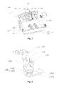
- FIG. 3 is a schematic perspective view of a banknote stacking and arranging device according to the present application.
- the banknote stacking and arranging device 100 includes a banknote conveying unit 110, a banknote stacking unit 120, and a banknote arranging unit 130.
- the banknote conveying unit 110 conveys the banknotes onto the banknote stacking shelf of the banknote stacking unit 120, and the banknotes being conveyed are stopped and tidied by the banknote arranging unit 130.
- the banknote conveying unit 110 includes a banknote guide platform 112 and a conveying wheel 114.
- the upper surface of the banknote guide platform 112 is a banknote guide platform surface 1122 with a wavy arc.
- the conveying wheel 114 is provided on the banknote guide platform 112 at the protruding arc-shaped portion of the banknote guide platform surface 1122.
- the conveying wheel 114 includes multiple banknote guide vanes 1142. Banknotes are conveyed onto the banknote guide platform surface 1122 of the banknote guide platform one by one in sequence by a conveying device, and slidingly fall between two banknote guide vanes 1142 of the conveying wheel 114. When the conveying wheel rotates, the banknotes are brought to rotate therewith so as to be conveyed to the banknote stacking unit 120.
- the banknote stacking unit 120 includes a fixing frame 122, a banknote stacking shelf 124 and a banknote baffle plate 126.
- the fixing frame 122 serves for supporting and fixing other parts or components.
- the banknote stacking shelf 124 is an "L"-shaped frame and is fixed on the fixing frame 122, and is adapted for the stacking and placement of banknotes A thereon.
- the banknote baffle plate 126 is arranged on the banknote stacking shelf 124 and perpendicular to the bottom part of the banknote stacking shelf 124, and is located behind the conveying wheel 124 such that the banknotes stand against the banknote baffle plate 126.
- the banknote baffle plate 126 is at an angle of 60 degrees with respect to the horizontal direction.
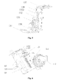
- FIG 4 is a schematic perspective view of a banknote arranging unit 130 of the banknote stacking and arranging device 100 shown in Figure 3
- Figure 5 is another schematic perspective view of the banknote arranging unit 130 of the banknote stacking and arranging device 100 shown in Figure 3
- the banknote arranging unit 130 includes a position-limiting plate 131, a locating plate 132, a position-limiting motor 133, a position-limiting rotating shaft 134, a locating gear 135, a fixed plate 136, a top plate 137 and a retractable portion 138.
- the fixed plate 136 is fixed on a fixing frame 122 of the banknote stacking unit 120, and is parallel to the banknote baffle plate 126 of the banknote stacking unit 120.
- the locating plate 132 is arranged on the fixed plate 136 and parallel to the fixed plate 136, and is movable up and down along the fixed plate 136.
- the locating plate 132 is provided with locating teeth 1322 in the direction perpendicular to the bottom face of the banknote stacking shelf 124.
- the position-limiting plate 131 is arranged under the locating plate 132 via a retractable portion 138.
- the position-limiting plate 131 includes a primary baffle plate 131a and a secondary baffle plate 131b angled with respect to each other.
- the primary baffle plate 131a is perpendicular to the banknote baffle plate 126, and the secondary baffle plate 131b tilts upwards slightly.
- the secondary baffle plate 131b and the primary baffle plate 131a form an angle of 30 to 45 degrees therebetween, and the secondary baffle plate 131b has a length of 10.8mm.
- the retractable portion 138 is composed of a guide shaft 1382 and a spring 1384 provided on the guide shaft 1382.
- the position-limiting plate 131 is flexible to move up and down via the retractable portion 138.
- the locating gear 135 is provided on the position-limiting rotating shaft 134, and is engaged with the locating teeth 1322 on the locating plate 132.
- the position-limiting motor 133 drives the position-limiting rotating shaft 134 to rotate, so that the locating gear 135 is rotated, which in turn brings the locating teeth 1322 to move up and down, so as to drive the locating plate 132 to move up and down along the fixed plate 136 and further drive the position-limiting plate 131 to move up and down.
- the top plate 137 is arranged at the top portion of the fixed plate 136 and is perpendicular to the fixed plate 136. When the locating plate 132 moves up and down along the fixed plate 136, the top plate 137 limits the maximum height of movement of the locating plate 132.
- FIG. 6 is a right view of the banknote stacking and arranging device shown in Figure 3 .
- the banknote conveying device (not shown) conveys the banknotes one by one in sequence onto the banknote guide platform surface 1122 of the banknote guide platform, and the banknotes slidingly fall between two banknote guide vanes 1142 of the conveying wheel 114.
- vanes of the conveying wheel 14 carry the banknotes on the banknote guide platform surface 1122 and rotate therewith in direction B. Due to the action of centrifugal force, the banknotes are thrown towards the banknote stacking shelf 124 while rotating.
- the banknotes move both at a first velocity component V1 in the direction perpendicular to the banknote baffle plate 126 and at a second velocity component V2 perpendicular to the first velocity component V1.
- the movement of the banknotes in the direction of the first velocity component V1 is blocked by the banknote baffle plate 26, and the movement of the banknotes in the direction of the second velocity component V2 is limited and blocked by the position-limiting plate 131, so that the banknotes may rest on the banknote stacking shelf 124 tidily.
- the position-limiting motor 133 drives the position-limiting rotating shaft 134 to rotate clockwise or anti-clockwise, and the locating gear 135 provided on the position-limiting rotating shaft 134 rotates along with the position-limiting rotating shaft 134.
- the locating teeth 1322 engaged with the locating gear 135 move up and down as the locating gear 135 rotates, and further drives the locating plate 132 to move up and down along the fixed plate 136.
- the position-limiting plate 131 arranged on the locating plate 132 moves as the locating plate 132 moves, so as to set the limit position of the position-limiting plate 131 actually according to different banknote specifications. Further, when a certain number (e.g.
- the position-limiting motor 133 drives the position-limiting plate 131 to press down the banknotes such that the spring 1384 may be compressed by 2mm. Therefore, the banknotes are stacked on the banknotes stacking shelf 124 tidily.
- the position-limiting plate 131 may also correct the angle of the stacking of the banknotes conveyed from the conveying wheel 114.
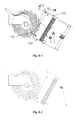
- Figures 8-1, 8-2 and 8-3 are schematic views showing the various steps at which the banknotes are tidied by the banknote stacking and arranging device 100 according to the present application.
- the banknote baffle plate 126 is at an angle of 60 degrees with respect to the horizontal plane; the bottom face of the banknote stacking shelf 124 is perpendicular to the banknote baffle plate 126; and the position-limiting plate 131 has a distance of 88mm from the bottom face of the banknote stacking shelf 124.
- the outer diameter of the conveying wheel 114 intersects the terminal end of the banknote guide platform 112 at point "a".
- the point “a” is also the starting point from which the banknotes just exit the conveying wheel 114, and has a distance of 4.4mm from the bottom face of the banknote stacking shelf 124.
- the straight line “ac” is perpendicular to the primary baffle plate 131a of the position-limiting plate 131, and point "c” is located on the primary baffle plate 131a.
- the length of a straight line “ab” is equal to the width of the banknotes of 85mm, and point “b” is located on the secondary baffle plate 131b of the position-limiting plate 131, and the distance between the point “b” and the point “c” is 2.4mm.
- the angle between the primary baffle plate 131a and the secondary baffle plate 131b of the position-limiting plate 131 is set to be 30 degrees, and the secondary baffle plate 131b has a length of 10.8mm.
- the secondary baffle plate 131b guides the banknotes downwards onto banknote stacking shelf 124, so as to avoid the banknotes to be caught.
- the distance “ac” between the point “a” and the primary baffle plate 131a of the position-limiting plate 131 is 83.6mm, which is less than the width of the banknote of 85mm.
- the banknote is at an angle of 67 degrees with respect to the horizontal plane.
- the banknote Because of the angle between the banknote and the horizontal plane less than 90 degrees, as well as the gravity of the banknote itself and the pushing force generated from the movement of the next banknote, the banknote finally is stacked on the banknote stacking shelf 124 at an angle of 60 degrees with respect to the horizontal plane, and leans plainly against the banknote baffle plate 126.
- the banknote stacking and arranging device is provided with a banknote arranging unit.
- the banknotes flying out from the conveying wheel are limited in position in the vertical direction via the position-limiting plate of the banknote arranging unit, and the movement angle of the banknote is corrected by the secondary baffle plate of the position-limiting plate.
- short edges of the banknotes may be tidied further, so that the banknotes may be tidily stacked on the banknote stacking shelf, which facilitate the next process of bundling the banknotes.
- the present application further provides a banknote stacking and arranging system.
- the banknote stacking and arranging system 300 includes a controller 200 and a banknote stacking and arranging device 100.
- Figure 7 is a structural block diagram of a controller 200 of a banknote stacking and arranging system according to the present application.
- the controller 200 includes a central control module 210, an image acquisition module 220, a detection module 230, a storage module 240, a data processing module 250, and an execution module 260.
- the central control module 210 is connected to the image acquisition module 220, the detection module 230, the storage module 240, the data processing module 250, and the execution module 260, so as to call and control the above modules and enable those modules to operate with each other harmoniously.
- the image acquisition module 220 includes a photoelectric sensor arranged on the banknote conveying unit 110 to acquire the image information of the banknotes and to store the information in the storage module 240.
- the detection module 230 includes a position sensor and a counting sensor.
- the position sensor is arranged on the fixed plate 136 of the banknote arranging unit 130 to detect the position of the position-limiting plate 131 or the locating tooth 1322 and to store the detected information in the storage module 240.
- the counting sensor is arranged on the banknote stacking shelf 124 or the banknote guide platform 112 to count the number of the banknotes.
- the storage module 240 stores image information of the banknotes, physical property information of the banknotes (including the width value of banknotes), the width value of the initial position of the position-limiting plate 131, a conversion formula for width adjustment, a conversion formula for converting the width adjustment value into the amount of movement of elements, or the like.
- the data processing module 250 invokes a conversion formula for adjusting the corresponding width and a conversion formula for the conversion amount of movement of the elements stored in the storage module 240 to perform data processing, so as to achieve a position parameter for adjusting the position-limiting plate 131 or the locating tooth 1322 and a drive parameter for driving the position-limiting motor 133.
- the execution module 260 generates servo signal for the execution elements according to the drive parameter of the data processing module 250, so as to drive the position-limiting motor 133 of the banknote stacking and arranging device 100 to rotate, and further adjust the current position of the position-limiting plate 131.
- the controller controls the banknote stacking and arranging device to press the edges of the banknotes and arrange the banknotes automatically and periodically.
- Different locating and arranging functions may be implemented according to different banknote specifications.
- the stacking and arranging system and the stacking and arranging device according to the present application are applicable for stacking and arranging other sheet mediums in addition to banknotes.
Landscapes
- Engineering & Computer Science (AREA)
- Mechanical Engineering (AREA)
- Physics & Mathematics (AREA)
- General Physics & Mathematics (AREA)
- Pile Receivers (AREA)
Abstract
Description
- The present application claims the benefit of priority to Chinese Patent Application No.
201210279637.X - The present application belongs to the field of financial apparatus, and relates to a stacking and arranging device for sheet mediums, and specifically to a banknote stacking and arranging device and a banknote stacking and arranging system.
- With the development and progress of science and technology, in some occasions that need to handle large amounts of cash, conventional manual procedures, such as sorting and counting, hundred separating, and bundling, have been gradually replaced by various types of advanced automatic processing systems. In the process of handling cashes, it is required to stack and arrange the banknotes.
- Referring to
Figure 1 together withFigure 2, Figure 1 is a schematic perspective view of a banknote stacking and arranging device in the prior art, andFigure 2 is a schematic view of conveying wheel shown inFigure 1 viewing from a sectional direction. The banknote stacking and arranging device includes abanknote conveying unit 10 and abanknote stacking unit 20 arranged behind thebanknote conveying unit 10. Thebanknote conveying unit 10 includes abanknote guide platform 12 and aconveying wheel 14. The upper surface of thebanknote guide platform 12 is a banknoteguide platform surface 121 with a wavy arc. The conveyingwheel 14 is provided on thebanknote guide platform 12 at a protruding arc-shaped portion of the banknoteguide platform surface 122. Thebanknote stacking unit 20 includes afixing frame 22, abanknote stacking shelf 24 and abanknote baffle plate 26. Thebanknote stacking shelf 24 is fixed on thefixing frame 22 and is of an "L" shape, and is adapted for the stacking of banknotes A thereon. Thebanknote baffle plate 26 is arranged on thebanknote stacking shelf 24 and is located behind the conveyingwheel 24 for stopping and holding the banknotes A. - As shown in
Figure 2 , when the conveyingwheel 14 rotates clockwise along the direction B, vanes of the conveyingwheel 14 carry the banknotes from the banknoteguide platform surface 121 and rotate together with those banknotes. Due to the action of centrifugal force, the banknotes are thrown towards thebanknote stacking shelf 24 while rotating. Thebanknote baffle plate 26 stops the further backward movement of the banknotes, so that the banknotes are stacked on thebanknote stacking shelf 24. However, during rotating at a high speed, due to the flexibility and elasticity of the banknotes themselves, the banknotes not only move backwards, but also move at an upward velocity component. Further, bounce movement of the banknotes may occur after falling on thebanknote stacking shelf 24. Hence, the banknotes may obliquely and disorderly lie on thebanknote stacking shelf 24, which may affect the next handling operation of arranging and stacking the banknotes. - In order to overcome the disadvantages or deficiencies in the prior art, an object of the present application is to provide a stacking and arranging device which is capable of stacking the banknotes tidily.
- The present application is implemented via the following technical solutions. A banknote stacking and arranging device is provided, including a banknote conveying unit, a banknote stacking unit and a banknote arranging unit. Specifically, the banknote conveying unit includes a banknote guide platform and a conveying wheel provided on the banknote guide platform. The banknote stacking unit includes a banknote stacking shelf and a banknote baffle plate arranged on the banknote stacking shelf. The banknote baffle plate is perpendicular to the bottom face of the banknote stacking shelf, and the banknote stacking shelf is arranged along the direction in which the banknotes are conveyed by the banknote conveying unit such as to facilitate stacking of banknotes. The banknote arranging unit includes a position-limiting plate arranged above the banknote stacking unit and being perpendicular to the banknote baffle plate.
- Further, the banknote arranging unit further includes a fixed plate and a locating plate. The fixed plate is fixedly arranged on the banknote stacking unit, and is perpendicular to the bottom face of the banknote stacking shelf. The locating plate is arranged on and parallel to the fixed plate, and is movable up and down along the fixed plate in the direction perpendicular to the bottom face of the banknote stacking shelf. The position-limiting plate is arranged on the locating plate.
- Further, the banknote arranging unit further includes a position-limiting rotating shaft, and a locating gear provided on the position-limiting rotating shaft. The locating plate is provided with locating teeth in the direction perpendicular to the bottom face of the banknote stacking shelf. The locating gear is engaged with the locating teeth.
- Further, the banknote arranging unit further includes a position-limiting motor. The position-limiting motor drives the position-limiting rotating shaft to rotate.
- Further, the banknote arranging unit further includes a top plate arranged at the top of the fixed plate and being perpendicular to the fixed plate.
- Further, the position-limiting plate is arranged under the locating plate via a retractable portion.
- The present application further provides a stacking and arranging system capable of stacking the banknotes tidily and automatically, which is implemented via the following technical solutions.
- A banknote stacking and arranging system is provided, including a controller and a banknote stacking and arranging device, with the controller controlling the operation of the banknote stacking and arranging device. Specifically, the banknote stacking and arranging device includes a banknote conveying unit, a banknote stacking unit, and a banknote arranging unit. Specifically, the banknote conveying unit includes a banknote guide platform and a conveying wheel provided on the banknote guide platform. The banknote stacking unit includes a banknote stacking shelf and a banknote baffle plate arranged on the banknote stacking shelf. The banknote baffle plate is perpendicular to the bottom face of the banknote stacking shelf, and the banknote stacking shelf is arranged along the direction in which the banknotes are conveyed by the banknote conveying unit such as to facilitate stacking of the banknotes. The banknote arranging unit includes a position-limiting plate arranged on the banknote stacking unit and being perpendicular to the banknote baffle plate.
- Further, the controller includes a central control module, and an image acquisition module, a data processing module, a storage module and an execution module which are electrically connected to the central control module. The central control module controls the image acquisition module to acquire banknote image information, and to transmit the banknote image information to the data processing module and to store the banknote image information in the storage module. The data processing module invokes a conversion formula stored in the storage module according to the banknote image information to perform data processing, generates a controlling parameter and sends the controlling parameter to the execution module. The execution module generates servo signals for execution elements so as to drive the position-limiting motor to rotate.
- Further, the banknote stacking and arranging system also includes a detection module electrically connected to the central control module. The central control module controls the detection module to detect position information of the position-limiting plate, to transmit the position information to the data processing module and to store the position information in the storage module. The data processing module invokes a conversion formula stored in the storage module according to the banknote image information and the position information of the position-limiting plate to perform data processing, generates a controlling parameter and sends the controlling parameter to the execution module. The execution module generates servo signals for the execution elements so as to drive the position-limiting motor to rotate.
- As compared with the techniques in the prior art, the banknote stacking and arranging device according to the present application is provided with a banknote arranging unit. The banknotes flying out from the conveying wheel are limited in the vertical direction by the position-limiting plate of the banknote arranging unit, and short edges of the banknotes are tidied, so that the banknotes may be tidily stacked on the banknote stacking shelf, which facilitates the next bundling process of the banknotes.
- As compared with the techniques in the prior art, according to the banknote stacking and arranging system in the present application, the controller controls the banknote stacking and arranging device to press the edges of the banknotes and arrange the banknotes automatically and periodically. Different locating and arranging functions can be realized according to different banknote specifications.
- In order to better understand the present application more clearly, specific embodiments of the present application will be set forth hereinafter in conjunction with the accompanying drawings.
-
-
Figure 1 is a schematic perspective view of a banknote stacking and arranging device in the prior art. -
Figure 2 is a right view of the banknote stacking and arranging device shown inFigure 1 . -
Figure 3 is a schematic perspective view of a banknote stacking and arranging device according to the present application. -
Figure 4 is a schematic perspective view of a banknote arranging unit of the banknote stacking and arranging device shown inFigure 3 . -
Figure 5 is another schematic perspective view of the banknote arranging unit of the banknote stacking and arranging device shown inFigure 3 . -
Figure 6 is a right view of the banknote stacking and arranging device shown inFigure 3 . -
Figure 7 is a structural block diagram of a controller of a banknote stacking and arranging system according to the present application. -
Figures 8-1, 8-2 and8-3 are schematic views showing the various steps at which the banknotes are tidied by the banknote stacking and arrangingdevice 100 according to the present application. - Please refer to
Figure 3 , which is a schematic perspective view of a banknote stacking and arranging device according to the present application. The banknote stacking and arrangingdevice 100 includes abanknote conveying unit 110, abanknote stacking unit 120, and abanknote arranging unit 130. Thebanknote conveying unit 110 conveys the banknotes onto the banknote stacking shelf of thebanknote stacking unit 120, and the banknotes being conveyed are stopped and tidied by thebanknote arranging unit 130. - Specifically, the
banknote conveying unit 110 includes abanknote guide platform 112 and a conveyingwheel 114. The upper surface of thebanknote guide platform 112 is a banknoteguide platform surface 1122 with a wavy arc. The conveyingwheel 114 is provided on thebanknote guide platform 112 at the protruding arc-shaped portion of the banknoteguide platform surface 1122. The conveyingwheel 114 includes multiple banknote guide vanes 1142. Banknotes are conveyed onto the banknoteguide platform surface 1122 of the banknote guide platform one by one in sequence by a conveying device, and slidingly fall between two banknote guide vanes 1142 of the conveyingwheel 114. When the conveying wheel rotates, the banknotes are brought to rotate therewith so as to be conveyed to thebanknote stacking unit 120. - The
banknote stacking unit 120 includes a fixingframe 122, abanknote stacking shelf 124 and abanknote baffle plate 126. The fixingframe 122 serves for supporting and fixing other parts or components. Thebanknote stacking shelf 124 is an "L"-shaped frame and is fixed on the fixingframe 122, and is adapted for the stacking and placement of banknotes A thereon. Thebanknote baffle plate 126 is arranged on thebanknote stacking shelf 124 and perpendicular to the bottom part of thebanknote stacking shelf 124, and is located behind the conveyingwheel 124 such that the banknotes stand against thebanknote baffle plate 126. Thebanknote baffle plate 126 is at an angle of 60 degrees with respect to the horizontal direction. - Referring to
Figure 4 together withFigure 5 ,Figure 4 is a schematic perspective view of abanknote arranging unit 130 of the banknote stacking and arrangingdevice 100 shown inFigure 3 , andFigure 5 is another schematic perspective view of thebanknote arranging unit 130 of the banknote stacking and arrangingdevice 100 shown inFigure 3 . Thebanknote arranging unit 130 includes a position-limitingplate 131, a locatingplate 132, a position-limitingmotor 133, a position-limitingrotating shaft 134, alocating gear 135, afixed plate 136, atop plate 137 and aretractable portion 138. The fixedplate 136 is fixed on a fixingframe 122 of thebanknote stacking unit 120, and is parallel to thebanknote baffle plate 126 of thebanknote stacking unit 120. The locatingplate 132 is arranged on the fixedplate 136 and parallel to the fixedplate 136, and is movable up and down along the fixedplate 136. The locatingplate 132 is provided with locatingteeth 1322 in the direction perpendicular to the bottom face of thebanknote stacking shelf 124. The position-limitingplate 131 is arranged under the locatingplate 132 via aretractable portion 138. The position-limitingplate 131 includes aprimary baffle plate 131a and asecondary baffle plate 131b angled with respect to each other. Theprimary baffle plate 131a is perpendicular to thebanknote baffle plate 126, and thesecondary baffle plate 131b tilts upwards slightly. Thesecondary baffle plate 131b and theprimary baffle plate 131a form an angle of 30 to 45 degrees therebetween, and thesecondary baffle plate 131b has a length of 10.8mm. Theretractable portion 138 is composed of aguide shaft 1382 and aspring 1384 provided on theguide shaft 1382. The position-limitingplate 131 is flexible to move up and down via theretractable portion 138. Thelocating gear 135 is provided on the position-limitingrotating shaft 134, and is engaged with the locatingteeth 1322 on the locatingplate 132. The position-limitingmotor 133 drives the position-limitingrotating shaft 134 to rotate, so that thelocating gear 135 is rotated, which in turn brings the locatingteeth 1322 to move up and down, so as to drive the locatingplate 132 to move up and down along the fixedplate 136 and further drive the position-limitingplate 131 to move up and down. Thetop plate 137 is arranged at the top portion of the fixedplate 136 and is perpendicular to the fixedplate 136. When the locatingplate 132 moves up and down along the fixedplate 136, thetop plate 137 limits the maximum height of movement of the locatingplate 132. - The operation principle of the banknote stacking and arranging
device 100 according to the present application will be described in detail hereinafter. - Please also refer to
Figure 6 , which is a right view of the banknote stacking and arranging device shown inFigure 3 . The banknote conveying device (not shown) conveys the banknotes one by one in sequence onto the banknoteguide platform surface 1122 of the banknote guide platform, and the banknotes slidingly fall between two banknote guide vanes 1142 of the conveyingwheel 114. When the conveyingwheel 14 rotates, vanes of the conveyingwheel 14 carry the banknotes on the banknoteguide platform surface 1122 and rotate therewith in direction B. Due to the action of centrifugal force, the banknotes are thrown towards thebanknote stacking shelf 124 while rotating. Here, the banknotes move both at a first velocity component V1 in the direction perpendicular to thebanknote baffle plate 126 and at a second velocity component V2 perpendicular to the first velocity component V1. The movement of the banknotes in the direction of the first velocity component V1 is blocked by thebanknote baffle plate 26, and the movement of the banknotes in the direction of the second velocity component V2 is limited and blocked by the position-limitingplate 131, so that the banknotes may rest on thebanknote stacking shelf 124 tidily. - The position-limiting
motor 133 drives the position-limitingrotating shaft 134 to rotate clockwise or anti-clockwise, and thelocating gear 135 provided on the position-limitingrotating shaft 134 rotates along with the position-limitingrotating shaft 134. The locatingteeth 1322 engaged with thelocating gear 135 move up and down as thelocating gear 135 rotates, and further drives the locatingplate 132 to move up and down along the fixedplate 136. The position-limitingplate 131 arranged on the locatingplate 132 moves as the locatingplate 132 moves, so as to set the limit position of the position-limitingplate 131 actually according to different banknote specifications. Further, when a certain number (e.g. 10 pieces) of the banknotes are stacked, the position-limitingmotor 133 drives the position-limitingplate 131 to press down the banknotes such that thespring 1384 may be compressed by 2mm. Therefore, the banknotes are stacked on thebanknotes stacking shelf 124 tidily. - Further, the position-limiting
plate 131 may also correct the angle of the stacking of the banknotes conveyed from the conveyingwheel 114. Please refer toFigures 8-1, 8-2 and8-3 , which are schematic views showing the various steps at which the banknotes are tidied by the banknote stacking and arrangingdevice 100 according to the present application. Taking the banknotes having a width of 85mm as an example, thebanknote baffle plate 126 is at an angle of 60 degrees with respect to the horizontal plane; the bottom face of thebanknote stacking shelf 124 is perpendicular to thebanknote baffle plate 126; and the position-limitingplate 131 has a distance of 88mm from the bottom face of thebanknote stacking shelf 124. The outer diameter of the conveyingwheel 114 intersects the terminal end of thebanknote guide platform 112 at point "a". The point "a" is also the starting point from which the banknotes just exit the conveyingwheel 114, and has a distance of 4.4mm from the bottom face of thebanknote stacking shelf 124. The straight line "ac" is perpendicular to theprimary baffle plate 131a of the position-limitingplate 131, and point "c" is located on theprimary baffle plate 131a. The length of a straight line "ab" is equal to the width of the banknotes of 85mm, and point "b" is located on thesecondary baffle plate 131b of the position-limitingplate 131, and the distance between the point "b" and the point "c" is 2.4mm. The angle between theprimary baffle plate 131a and thesecondary baffle plate 131b of the position-limitingplate 131 is set to be 30 degrees, and thesecondary baffle plate 131b has a length of 10.8mm. Thesecondary baffle plate 131b guides the banknotes downwards ontobanknote stacking shelf 124, so as to avoid the banknotes to be caught. - In
Figure 8-1 , when the conveyingwheel 114 rotates clockwise, and the banknote rotates along with the conveyingwheel 114, one end of the banknote is firstly stopped by the end of thesecondary baffle plate 131b of the position-limitingplate 131. At this time, the banknote is at an angle of 70 degrees with respect to the horizontal plane. The conveyingwheel 114 keeps on rotating clockwise, and the end of the banknote slides downwards along thesecondary baffle plate 131b of the position-limitingplate 131. InFigure 8-2 , the end of the banknote located on the conveyingwheel 114 rotates to point "a" so as to just exit the conveyingwheel 114. Since the point "a" has a distance of 4.4mm from the bottom face of thebanknote stacking shelf 124, the distance "ac" between the point "a" and theprimary baffle plate 131a of the position-limitingplate 131 is 83.6mm, which is less than the width of the banknote of 85mm. Thus, when the end of the banknote on the conveyingwheel 114 rotates to point "a", the other end of the banknote still abuts against thesecondary baffle plate 131b of the position-limitingplate 131. At this moment, the banknote is at an angle of 69 degrees with respect to the horizontal plane. As the conveyingwheel 114 keeps on rotating clockwise, the end of the banknote located on the conveyingwheel 114 completely move away from the conveyingwheel 114, and the other end of the banknote continues to slide downwards along thesecondary baffle plate 131b of the position-limitingplate 131. InFigure 8-3 , the banknote is at an angle of 67 degrees with respect to the horizontal plane. - Because of the angle between the banknote and the horizontal plane less than 90 degrees, as well as the gravity of the banknote itself and the pushing force generated from the movement of the next banknote, the banknote finally is stacked on the
banknote stacking shelf 124 at an angle of 60 degrees with respect to the horizontal plane, and leans plainly against thebanknote baffle plate 126. - Compared with the techniques in the prior art, the banknote stacking and arranging device according to the present application is provided with a banknote arranging unit. The banknotes flying out from the conveying wheel are limited in position in the vertical direction via the position-limiting plate of the banknote arranging unit, and the movement angle of the banknote is corrected by the secondary baffle plate of the position-limiting plate. Besides, short edges of the banknotes may be tidied further, so that the banknotes may be tidily stacked on the banknote stacking shelf, which facilitate the next process of bundling the banknotes.
- Further, in order to achieve the automatic detection and control functions of the banknote stacking and arranging device, the present application further provides a banknote stacking and arranging system. The banknote stacking and arranging system 300 includes a
controller 200 and a banknote stacking and arrangingdevice 100. Please refer toFigure 7 , which is a structural block diagram of acontroller 200 of a banknote stacking and arranging system according to the present application. Thecontroller 200 includes acentral control module 210, animage acquisition module 220, adetection module 230, astorage module 240, adata processing module 250, and anexecution module 260. - The
central control module 210 is connected to theimage acquisition module 220, thedetection module 230, thestorage module 240, thedata processing module 250, and theexecution module 260, so as to call and control the above modules and enable those modules to operate with each other harmoniously. - The
image acquisition module 220 includes a photoelectric sensor arranged on thebanknote conveying unit 110 to acquire the image information of the banknotes and to store the information in thestorage module 240. - The
detection module 230 includes a position sensor and a counting sensor. The position sensor is arranged on the fixedplate 136 of thebanknote arranging unit 130 to detect the position of the position-limitingplate 131 or the locatingtooth 1322 and to store the detected information in thestorage module 240. The counting sensor is arranged on thebanknote stacking shelf 124 or thebanknote guide platform 112 to count the number of the banknotes. - The
storage module 240 stores image information of the banknotes, physical property information of the banknotes (including the width value of banknotes), the width value of the initial position of the position-limitingplate 131, a conversion formula for width adjustment, a conversion formula for converting the width adjustment value into the amount of movement of elements, or the like. - According to the image information acquired by the
image acquisition module 220, the initial position of the position-limitingplate 131 detected by thedetection module 230, and the number of the stacked banknotes detected by the counting sensor, thedata processing module 250 invokes a conversion formula for adjusting the corresponding width and a conversion formula for the conversion amount of movement of the elements stored in thestorage module 240 to perform data processing, so as to achieve a position parameter for adjusting the position-limitingplate 131 or the locatingtooth 1322 and a drive parameter for driving the position-limitingmotor 133. - The
execution module 260 generates servo signal for the execution elements according to the drive parameter of thedata processing module 250, so as to drive the position-limitingmotor 133 of the banknote stacking and arrangingdevice 100 to rotate, and further adjust the current position of the position-limitingplate 131. - The operation process of the banknote stacking and arranging system 300 is described in detail hereinafter.
- 1) When the conveying
wheel 114 rotates, thecentral control module 210 controls the photoelectric sensor of theimage acquisition module 220 to acquire the image information of the banknotes and to transmit the information to thedata processing module 250 and to store the information in thestorage module 240. - 2) Meanwhile, the
central control module 210 controls the position sensor of thedetection module 230 to detect the current initial position of the position-limitingplate 131, and to transmit the data to thedata processing module 250, and to store the data in thestorage module 240. - 3) The
central control module 210 controls thedata processing module 250 to invoke the conversion formulas stored in thestorage module 240 for adjusting the width and for converting the amount of movement of the elements according to the current banknote image information and the current initial position of the position-limitingplate 131 to perform data processing, so as to generate a position parameter for adjusting the position-limitingplate 131 or the locatingtooth 1322 and a drive parameter for driving the position-limitingmotor 133. - 4) The
central control module 210 controls the execution module to generate servo signal for the execution elements according to the drive parameter from thedata processing module 250, so as to drive the position-limitingmotor 133 to rotate, and further adjust the upward or downward movement of the position-limitingplate 131.
Taking the banknotes having a width of 85mm as an example, thecontroller 200 controls the position-limitingmotor 133 to rotate, so as to drive the position-limitingplate 131 to move such as to be 88mm apart from the bottom face of thebanknote stacking shelf 124. - 5)
Central control module 210 also controls the counting sensor of thedetection module 230 to monitor the number of the banknotes on thebanknote stacking shelf 124. When a certain number of banknotes have been stacked, for example 10 pieces, thecentral control module 210 controls theexecution module 260 to drive the position-limitingmotor 133 to rotate. As such, the position-limitingplate 131 is driven to press the banknotes downwards until causing an interference of 2mm with respect to the banknotes, and then returns, thereby arranging the short edges of the banknotes. - 6) The
central control module 210 also controls the counting sensor of thedetection module 230 to monitor the number of the banknotes on thebanknote stacking shelf 124. When a certain number of banknotes have been stacked, for example 100 pieces, thecentral control module 210 controls theexecution module 260 to drive the position-limitingmotor 133 to rotate. As such, the position-limitingplate 131 is driven to press the banknotes downwards until causing an interference of 2mm with respect to the banknotes, and then returns. Then, thebanknote stacking shelf 124 is further driven to bring the whole stack of the banknotes to move downwards, and to send the banknotes to a clamping mechanism (not shown) which sends the banknotes to a bundling mechanism for being bundled. - As compared with the techniques in the prior art, according to the banknote stacking and arranging system in the present application, the controller controls the banknote stacking and arranging device to press the edges of the banknotes and arrange the banknotes automatically and periodically. Different locating and arranging functions may be implemented according to different banknote specifications. The stacking and arranging system and the stacking and arranging device according to the present application are applicable for stacking and arranging other sheet mediums in addition to banknotes.
- The present application is not limited to the above embodiments. If various variations or modifications to the present application do not depart from the spirit and scope of the present application, and if these variations and modifications fall within the scope of the claims and equivalent techniques of the present application, it is intended that the present application includes those variations and modifications.
Claims (10)
- A banknote stacking and arranging device, comprising:a banknote conveying unit comprising a banknote guide platform and a conveying wheel provided on the banknote guide platform;a banknote stacking unit comprising a banknote stacking shelf and a banknote baffle plate arranged on the banknote stacking shelf, with the banknote baffle plate being perpendicular to a bottom face of the banknote stacking shelf, and the banknote stacking shelf being arranged along a direction in which banknotes are conveyed by the banknote conveying unit such as to facilitate stacking of the banknotes thereon; anda banknote arranging unit comprising a position-limiting plate which is arranged above the banknote stacking unit and is perpendicular to the banknote baffle plate.
- The banknote stacking and arranging device according to claim 1, wherein the banknote arranging unit further comprises a fixed plate and a locating plate, the fixed plate is fixedly arranged on the banknote stacking unit and is perpendicular to the bottom face of the banknote stacking shelf, the locating plate is arranged on and parallel to the fixed plate and is movable up and down along the fixed plate in a direction perpendicular to the bottom face of the banknote stacking shelf, and the position-limiting plate is arranged on the locating plate.
- The banknote stacking and arranging device according to claim 2, wherein the position-limiting plate is arranged under the locating plate via a retractable portion.
- The banknote stacking and arranging device according to claim 3, wherein the position-limiting plate comprises a primary baffle plate and a secondary baffle plate angled by 30 to 45 degrees with respect to each other, the primary baffle plate is perpendicular to the banknote baffle plate.
- A banknote stacking and arranging system, comprising a controller and the banknote stacking and arranging device according to claim 4, wherein the controller controls operation of the banknote stacking and arranging device.
- The banknote stacking and arranging system according to claim 5, wherein the controller comprises a central control module, and an image acquisition module, a data processing module, a storage module and an execution module which are electrically connected to the central control module; and
wherein the central control module controls the image acquisition module to acquire banknote image information and to transmit the banknote image information to the data processing module and to store the banknote image information in the storage module; and
wherein the data processing module invokes a conversion formula stored in the storage module according to the banknote image information to perform data processing, generates a controlling parameter and sends the controlling parameter to the execution module; and wherein the execution module generates servo signals for execution elements so as to drive the position-limiting motor to rotate. - The banknote stacking and arranging system according to claim 6, further comprising a detection module electrically connected to the central control module,
wherein the central control module controls the detection module to detect position information of the position-limiting plate and to transmit the position information to the data processing module and to store the position information in the storage module; and
wherein the data processing module invokes a conversion formula stored in the storage module according to the banknote image information and the position information of the position-limiting plate to perform data processing, generates a controlling parameter and sends the controlling parameter to the execution module; and
wherein the execution module generates servo signals for the execution elements so as to drive the position-limiting motor to rotate. - The banknote stacking and arranging system according to claim 7, wherein the image acquisition module comprises a photoelectric sensor arranged on the banknote conveying unit.
- The banknote stacking and arranging system according to claim 7 or 8, wherein the detection module comprises a position sensor arranged on the fixed plate of the banknote arranging unit.
- The banknote stacking and arranging system according to claim 9, wherein the detection module further comprises a counting sensor arranged on the banknote stacking shelf or the banknote guide platform.
Applications Claiming Priority (2)
| Application Number | Priority Date | Filing Date | Title |
|---|---|---|---|
| CN201210279637.XA CN102774683B (en) | 2012-08-07 | 2012-08-07 | Bill stacking and sorting device and bill stacking and sorting system |
| PCT/CN2013/073926 WO2014023107A1 (en) | 2012-08-07 | 2013-04-09 | Bank note stacking and sorting device and bank note stacking and sorting system |
Publications (3)
| Publication Number | Publication Date |
|---|---|
| EP2883823A1 true EP2883823A1 (en) | 2015-06-17 |
| EP2883823A4 EP2883823A4 (en) | 2017-07-12 |
| EP2883823B1 EP2883823B1 (en) | 2018-12-05 |
Family
ID=47119831
Family Applications (1)
| Application Number | Title | Priority Date | Filing Date |
|---|---|---|---|
| EP13827235.6A Active EP2883823B1 (en) | 2012-08-07 | 2013-04-09 | Banknote stacking and aranging device |
Country Status (9)
| Country | Link |
|---|---|
| US (1) | US9260265B2 (en) |
| EP (1) | EP2883823B1 (en) |
| CN (1) | CN102774683B (en) |
| AU (1) | AU2013302147B2 (en) |
| CL (1) | CL2015000242A1 (en) |
| IN (1) | IN2015DN01177A (en) |
| TR (1) | TR201819234T4 (en) |
| WO (1) | WO2014023107A1 (en) |
| ZA (1) | ZA201500889B (en) |
Families Citing this family (13)
| Publication number | Priority date | Publication date | Assignee | Title |
|---|---|---|---|---|
| CN102774683B (en) | 2012-08-07 | 2015-01-14 | 广州广电运通金融电子股份有限公司 | Bill stacking and sorting device and bill stacking and sorting system |
| CN103116938A (en) * | 2013-01-11 | 2013-05-22 | 广州广电运通金融电子股份有限公司 | Bill stacking device |
| CN103226868B (en) * | 2013-04-26 | 2015-02-11 | 中国工商银行股份有限公司 | Automatic paper money binding system of ATM |
| CN103646466B (en) * | 2013-12-30 | 2016-04-20 | 广州广电运通金融电子股份有限公司 | Hot Wheels fold paper money device |
| CN103955993A (en) * | 2014-04-24 | 2014-07-30 | 中国人民银行印制科学技术研究所 | Bill collection and arranging device and method and bill sorting equipment |
| CN103979298B (en) * | 2014-05-30 | 2016-02-03 | 湖南辰泰信息科技股份有限公司 | Atm stacker |
| CN104670965B (en) * | 2015-03-26 | 2017-03-01 | 广州广电运通金融电子股份有限公司 | A kind of bank note stacking apparatus and bill handling apparatus |
| CN105184959A (en) * | 2015-09-15 | 2015-12-23 | 昆山古鳌电子机械有限公司 | Paper processing apparatus |
| JP6611644B2 (en) * | 2016-03-18 | 2019-11-27 | グローリー株式会社 | Paper sheet stacking mechanism and paper sheet processing apparatus |
| CN105775260B (en) * | 2016-03-24 | 2017-12-19 | 广州中智融通金融科技有限公司 | Paper currency sorting streamline and its paper money are affixed one's seal code-spraying equipment |
| CN106644551B (en) * | 2017-02-22 | 2023-06-16 | 广东顺德华焱电子科技有限公司 | Service life testing device of reinforcing steel bar binding machine |
| CN111127741A (en) * | 2019-12-27 | 2020-05-08 | 恒银金融科技股份有限公司 | Auxiliary banknote stacking mechanism and working method thereof |
| CN114973537B (en) * | 2021-02-26 | 2024-07-12 | 深圳怡化电脑股份有限公司 | Banknote processing control method and device, electronic equipment and storage medium |
Family Cites Families (15)
| Publication number | Priority date | Publication date | Assignee | Title |
|---|---|---|---|---|
| JPS6279158A (en) * | 1985-09-30 | 1987-04-11 | Toshiba Corp | Paper sheet stacker |
| JP2860612B2 (en) | 1991-05-24 | 1999-02-24 | 株式会社イソワ | Method and apparatus for laminating plate-like sheets |
| JPH06279158A (en) | 1993-03-23 | 1994-10-04 | Tokai Plant Eng Kk | Fermentation composting method for organic matter |
| JPH09278262A (en) * | 1996-04-10 | 1997-10-28 | Omron Corp | Paper sheet stacking device and transaction processing device |
| JPH11240663A (en) * | 1998-02-25 | 1999-09-07 | Sanyo Electric Co Ltd | Bank note storage device |
| JP4160362B2 (en) | 2002-10-30 | 2008-10-01 | グローリー株式会社 | Accumulator and circulating banknote deposit and withdrawal machine |
| JP4861641B2 (en) | 2005-04-21 | 2012-01-25 | 株式会社オーイズミ | Banknote handling equipment |
| JP2006350921A (en) * | 2005-06-20 | 2006-12-28 | Toshiba Corp | Paper sheet processing equipment |
| KR100754050B1 (en) * | 2006-06-30 | 2007-08-31 | 노틸러스효성 주식회사 | Banknote guide device of automatic teller machine |
| JP4715656B2 (en) | 2006-07-05 | 2011-07-06 | 沖電気工業株式会社 | Media processing device |
| JP2008084170A (en) * | 2006-09-28 | 2008-04-10 | Toshiba Corp | Paper sheet processing apparatus and impeller stacking apparatus used therefor |
| KR101252193B1 (en) | 2006-10-06 | 2013-04-05 | 글로리 가부시키가이샤 | Paper currency processing device, and control method for paper currency processing device |
| JP5385179B2 (en) * | 2010-02-26 | 2014-01-08 | 富士通フロンテック株式会社 | Paper sheet stacking device |
| CN102275658B (en) * | 2011-04-20 | 2013-07-24 | 广州广电运通金融电子股份有限公司 | Adaptive sorting device for bulk medium |
| CN102774683B (en) | 2012-08-07 | 2015-01-14 | 广州广电运通金融电子股份有限公司 | Bill stacking and sorting device and bill stacking and sorting system |
-
2012
- 2012-08-07 CN CN201210279637.XA patent/CN102774683B/en active Active
-
2013
- 2013-04-09 AU AU2013302147A patent/AU2013302147B2/en not_active Ceased
- 2013-04-09 US US14/416,612 patent/US9260265B2/en active Active
- 2013-04-09 WO PCT/CN2013/073926 patent/WO2014023107A1/en not_active Ceased
- 2013-04-09 EP EP13827235.6A patent/EP2883823B1/en active Active
- 2013-04-09 TR TR2018/19234T patent/TR201819234T4/en unknown
-
2015
- 2015-01-30 CL CL2015000242A patent/CL2015000242A1/en unknown
- 2015-02-06 ZA ZA2015/00889A patent/ZA201500889B/en unknown
- 2015-02-13 IN IN1177DEN2015 patent/IN2015DN01177A/en unknown
Non-Patent Citations (1)
| Title |
|---|
| See references of WO2014023107A1 * |
Also Published As
| Publication number | Publication date |
|---|---|
| CN102774683A (en) | 2012-11-14 |
| WO2014023107A1 (en) | 2014-02-13 |
| CN102774683B (en) | 2015-01-14 |
| IN2015DN01177A (en) | 2015-06-26 |
| US20150203318A1 (en) | 2015-07-23 |
| TR201819234T4 (en) | 2019-01-21 |
| US9260265B2 (en) | 2016-02-16 |
| CL2015000242A1 (en) | 2015-05-22 |
| AU2013302147B2 (en) | 2015-10-29 |
| ZA201500889B (en) | 2016-04-28 |
| AU2013302147A1 (en) | 2015-02-12 |
| EP2883823A4 (en) | 2017-07-12 |
| EP2883823B1 (en) | 2018-12-05 |
Similar Documents
| Publication | Publication Date | Title |
|---|---|---|
| US9260265B2 (en) | Bank note stacking and sorting device and bank note stacking and sorting system | |
| JP6026291B2 (en) | Integrated sealing device | |
| US8899580B2 (en) | Sheet-type medium stacking and guiding device, as well as control system and method based on the same | |
| US8276902B2 (en) | Device for handling single sheets, for introducing rectangular individual sheets into a container | |
| EP3185222B1 (en) | Rotary paper money conveying device | |
| EP2793200A1 (en) | Sorting and bundling all-in-one machine and banknote stacking and sorting module thereof | |
| US10011128B2 (en) | Paper discharging mechanism and printing device having the same | |
| EP2623450B1 (en) | Bundling apparatus for sheet-type medium | |
| RU2562791C1 (en) | Processing device of paper sheets | |
| CN100524372C (en) | Paper sheet processing apparatus | |
| KR20120107828A (en) | Accumulating and strapping apparatus | |
| CN106023418A (en) | Rotary banknote sorting device | |
| JP2014108795A (en) | Paper sheet processing device | |
| US11113920B2 (en) | Banknote stacking and separating apparatus and banknote processing device | |
| KR102008574B1 (en) | Apparatus for stacking paper money | |
| CN1151055C (en) | Paper pile accumulation device and paper pile processing device | |
| US12243368B2 (en) | Check handling device | |
| US11989993B2 (en) | Banknote accumulating device, limiting mechanism and cash recycling and handling device | |
| JP5310028B2 (en) | Sheet aligning device, sheet aligning method, sheet aligning program, and image forming apparatus | |
| JPH087067A (en) | Method and device for counting paper sheet or the like | |
| JPH0714299Y2 (en) | Sorter | |
| JP2016155689A (en) | Paper sheet counting device | |
| US9174470B2 (en) | Recording apparatus | |
| JP5958154B2 (en) | Sheet discharging apparatus and image recording apparatus provided with the same | |
| JPS6320595A (en) | Paper circulation rate detection device |
Legal Events
| Date | Code | Title | Description |
|---|---|---|---|
| PUAI | Public reference made under article 153(3) epc to a published international application that has entered the european phase |
Free format text: ORIGINAL CODE: 0009012 |
|
| 17P | Request for examination filed |
Effective date: 20150121 |
|
| AK | Designated contracting states |
Kind code of ref document: A1 Designated state(s): AL AT BE BG CH CY CZ DE DK EE ES FI FR GB GR HR HU IE IS IT LI LT LU LV MC MK MT NL NO PL PT RO RS SE SI SK SM TR |
|
| AX | Request for extension of the european patent |
Extension state: BA ME |
|
| DAX | Request for extension of the european patent (deleted) | ||
| RA4 | Supplementary search report drawn up and despatched (corrected) |
Effective date: 20170613 |
|
| RIC1 | Information provided on ipc code assigned before grant |
Ipc: B65H 29/40 20060101ALI20170607BHEP Ipc: B65H 31/38 20060101AFI20170607BHEP Ipc: B65H 29/52 20060101ALI20170607BHEP Ipc: G07D 13/00 20060101ALI20170607BHEP Ipc: B65H 43/00 20060101ALI20170607BHEP Ipc: B65H 31/02 20060101ALI20170607BHEP |
|
| REG | Reference to a national code |
Ref country code: DE Ref legal event code: R079 Ref document number: 602013047907 Country of ref document: DE Free format text: PREVIOUS MAIN CLASS: B65H0031340000 Ipc: B65H0031200000 |
|
| RIC1 | Information provided on ipc code assigned before grant |
Ipc: B65H 31/20 20060101AFI20180619BHEP Ipc: B65H 43/00 20060101ALI20180619BHEP Ipc: B65H 31/38 20060101ALI20180619BHEP Ipc: G07D 13/00 20060101ALI20180619BHEP Ipc: B65H 29/52 20060101ALI20180619BHEP Ipc: B65H 29/40 20060101ALI20180619BHEP Ipc: B65H 31/02 20060101ALI20180619BHEP |
|
| GRAP | Despatch of communication of intention to grant a patent |
Free format text: ORIGINAL CODE: EPIDOSNIGR1 |
|
| STAA | Information on the status of an ep patent application or granted ep patent |
Free format text: STATUS: GRANT OF PATENT IS INTENDED |
|
| INTG | Intention to grant announced |
Effective date: 20180727 |
|
| GRAS | Grant fee paid |
Free format text: ORIGINAL CODE: EPIDOSNIGR3 |
|
| GRAA | (expected) grant |
Free format text: ORIGINAL CODE: 0009210 |
|
| STAA | Information on the status of an ep patent application or granted ep patent |
Free format text: STATUS: THE PATENT HAS BEEN GRANTED |
|
| AK | Designated contracting states |
Kind code of ref document: B1 Designated state(s): AL AT BE BG CH CY CZ DE DK EE ES FI FR GB GR HR HU IE IS IT LI LT LU LV MC MK MT NL NO PL PT RO RS SE SI SK SM TR |
|
| REG | Reference to a national code |
Ref country code: GB Ref legal event code: FG4D |
|
| REG | Reference to a national code |
Ref country code: CH Ref legal event code: EP |
|
| REG | Reference to a national code |
Ref country code: AT Ref legal event code: REF Ref document number: 1072780 Country of ref document: AT Kind code of ref document: T Effective date: 20181215 |
|
| REG | Reference to a national code |
Ref country code: IE Ref legal event code: FG4D |
|
| REG | Reference to a national code |
Ref country code: DE Ref legal event code: R096 Ref document number: 602013047907 Country of ref document: DE |
|
| REG | Reference to a national code |
Ref country code: NL Ref legal event code: MP Effective date: 20181205 |
|
| REG | Reference to a national code |
Ref country code: LT Ref legal event code: MG4D |
|
| PG25 | Lapsed in a contracting state [announced via postgrant information from national office to epo] |
Ref country code: FI Free format text: LAPSE BECAUSE OF FAILURE TO SUBMIT A TRANSLATION OF THE DESCRIPTION OR TO PAY THE FEE WITHIN THE PRESCRIBED TIME-LIMIT Effective date: 20181205 Ref country code: BG Free format text: LAPSE BECAUSE OF FAILURE TO SUBMIT A TRANSLATION OF THE DESCRIPTION OR TO PAY THE FEE WITHIN THE PRESCRIBED TIME-LIMIT Effective date: 20190305 Ref country code: NO Free format text: LAPSE BECAUSE OF FAILURE TO SUBMIT A TRANSLATION OF THE DESCRIPTION OR TO PAY THE FEE WITHIN THE PRESCRIBED TIME-LIMIT Effective date: 20190305 Ref country code: LT Free format text: LAPSE BECAUSE OF FAILURE TO SUBMIT A TRANSLATION OF THE DESCRIPTION OR TO PAY THE FEE WITHIN THE PRESCRIBED TIME-LIMIT Effective date: 20181205 Ref country code: ES Free format text: LAPSE BECAUSE OF FAILURE TO SUBMIT A TRANSLATION OF THE DESCRIPTION OR TO PAY THE FEE WITHIN THE PRESCRIBED TIME-LIMIT Effective date: 20181205 Ref country code: HR Free format text: LAPSE BECAUSE OF FAILURE TO SUBMIT A TRANSLATION OF THE DESCRIPTION OR TO PAY THE FEE WITHIN THE PRESCRIBED TIME-LIMIT Effective date: 20181205 Ref country code: LV Free format text: LAPSE BECAUSE OF FAILURE TO SUBMIT A TRANSLATION OF THE DESCRIPTION OR TO PAY THE FEE WITHIN THE PRESCRIBED TIME-LIMIT Effective date: 20181205 |
|
| PG25 | Lapsed in a contracting state [announced via postgrant information from national office to epo] |
Ref country code: AL Free format text: LAPSE BECAUSE OF FAILURE TO SUBMIT A TRANSLATION OF THE DESCRIPTION OR TO PAY THE FEE WITHIN THE PRESCRIBED TIME-LIMIT Effective date: 20181205 Ref country code: SE Free format text: LAPSE BECAUSE OF FAILURE TO SUBMIT A TRANSLATION OF THE DESCRIPTION OR TO PAY THE FEE WITHIN THE PRESCRIBED TIME-LIMIT Effective date: 20181205 Ref country code: RS Free format text: LAPSE BECAUSE OF FAILURE TO SUBMIT A TRANSLATION OF THE DESCRIPTION OR TO PAY THE FEE WITHIN THE PRESCRIBED TIME-LIMIT Effective date: 20181205 Ref country code: GR Free format text: LAPSE BECAUSE OF FAILURE TO SUBMIT A TRANSLATION OF THE DESCRIPTION OR TO PAY THE FEE WITHIN THE PRESCRIBED TIME-LIMIT Effective date: 20190306 |
|
| PG25 | Lapsed in a contracting state [announced via postgrant information from national office to epo] |
Ref country code: NL Free format text: LAPSE BECAUSE OF FAILURE TO SUBMIT A TRANSLATION OF THE DESCRIPTION OR TO PAY THE FEE WITHIN THE PRESCRIBED TIME-LIMIT Effective date: 20181205 |
|
| PG25 | Lapsed in a contracting state [announced via postgrant information from national office to epo] |
Ref country code: CZ Free format text: LAPSE BECAUSE OF FAILURE TO SUBMIT A TRANSLATION OF THE DESCRIPTION OR TO PAY THE FEE WITHIN THE PRESCRIBED TIME-LIMIT Effective date: 20181205 Ref country code: PL Free format text: LAPSE BECAUSE OF FAILURE TO SUBMIT A TRANSLATION OF THE DESCRIPTION OR TO PAY THE FEE WITHIN THE PRESCRIBED TIME-LIMIT Effective date: 20181205 Ref country code: PT Free format text: LAPSE BECAUSE OF FAILURE TO SUBMIT A TRANSLATION OF THE DESCRIPTION OR TO PAY THE FEE WITHIN THE PRESCRIBED TIME-LIMIT Effective date: 20190405 |
|
| PG25 | Lapsed in a contracting state [announced via postgrant information from national office to epo] |
Ref country code: EE Free format text: LAPSE BECAUSE OF FAILURE TO SUBMIT A TRANSLATION OF THE DESCRIPTION OR TO PAY THE FEE WITHIN THE PRESCRIBED TIME-LIMIT Effective date: 20181205 Ref country code: SM Free format text: LAPSE BECAUSE OF FAILURE TO SUBMIT A TRANSLATION OF THE DESCRIPTION OR TO PAY THE FEE WITHIN THE PRESCRIBED TIME-LIMIT Effective date: 20181205 Ref country code: RO Free format text: LAPSE BECAUSE OF FAILURE TO SUBMIT A TRANSLATION OF THE DESCRIPTION OR TO PAY THE FEE WITHIN THE PRESCRIBED TIME-LIMIT Effective date: 20181205 Ref country code: IS Free format text: LAPSE BECAUSE OF FAILURE TO SUBMIT A TRANSLATION OF THE DESCRIPTION OR TO PAY THE FEE WITHIN THE PRESCRIBED TIME-LIMIT Effective date: 20190405 Ref country code: SK Free format text: LAPSE BECAUSE OF FAILURE TO SUBMIT A TRANSLATION OF THE DESCRIPTION OR TO PAY THE FEE WITHIN THE PRESCRIBED TIME-LIMIT Effective date: 20181205 |
|
| REG | Reference to a national code |
Ref country code: DE Ref legal event code: R097 Ref document number: 602013047907 Country of ref document: DE |
|
| PLBE | No opposition filed within time limit |
Free format text: ORIGINAL CODE: 0009261 |
|
| STAA | Information on the status of an ep patent application or granted ep patent |
Free format text: STATUS: NO OPPOSITION FILED WITHIN TIME LIMIT |
|
| PG25 | Lapsed in a contracting state [announced via postgrant information from national office to epo] |
Ref country code: DK Free format text: LAPSE BECAUSE OF FAILURE TO SUBMIT A TRANSLATION OF THE DESCRIPTION OR TO PAY THE FEE WITHIN THE PRESCRIBED TIME-LIMIT Effective date: 20181205 Ref country code: SI Free format text: LAPSE BECAUSE OF FAILURE TO SUBMIT A TRANSLATION OF THE DESCRIPTION OR TO PAY THE FEE WITHIN THE PRESCRIBED TIME-LIMIT Effective date: 20181205 |
|
| PGFP | Annual fee paid to national office [announced via postgrant information from national office to epo] |
Ref country code: AT Payment date: 20190430 Year of fee payment: 7 |
|
| 26N | No opposition filed |
Effective date: 20190906 |
|
| REG | Reference to a national code |
Ref country code: CH Ref legal event code: PL |
|
| REG | Reference to a national code |
Ref country code: BE Ref legal event code: MM Effective date: 20190430 |
|
| PG25 | Lapsed in a contracting state [announced via postgrant information from national office to epo] |
Ref country code: MC Free format text: LAPSE BECAUSE OF FAILURE TO SUBMIT A TRANSLATION OF THE DESCRIPTION OR TO PAY THE FEE WITHIN THE PRESCRIBED TIME-LIMIT Effective date: 20181205 Ref country code: LU Free format text: LAPSE BECAUSE OF NON-PAYMENT OF DUE FEES Effective date: 20190409 |
|
| PG25 | Lapsed in a contracting state [announced via postgrant information from national office to epo] |
Ref country code: LI Free format text: LAPSE BECAUSE OF NON-PAYMENT OF DUE FEES Effective date: 20190430 Ref country code: CH Free format text: LAPSE BECAUSE OF NON-PAYMENT OF DUE FEES Effective date: 20190430 |
|
| PG25 | Lapsed in a contracting state [announced via postgrant information from national office to epo] |
Ref country code: BE Free format text: LAPSE BECAUSE OF NON-PAYMENT OF DUE FEES Effective date: 20190430 |
|
| PG25 | Lapsed in a contracting state [announced via postgrant information from national office to epo] |
Ref country code: IE Free format text: LAPSE BECAUSE OF NON-PAYMENT OF DUE FEES Effective date: 20190409 |
|
| REG | Reference to a national code |
Ref country code: AT Ref legal event code: MM01 Ref document number: 1072780 Country of ref document: AT Kind code of ref document: T Effective date: 20200409 |
|
| PG25 | Lapsed in a contracting state [announced via postgrant information from national office to epo] |
Ref country code: AT Free format text: LAPSE BECAUSE OF NON-PAYMENT OF DUE FEES Effective date: 20200409 |
|
| PG25 | Lapsed in a contracting state [announced via postgrant information from national office to epo] |
Ref country code: CY Free format text: LAPSE BECAUSE OF FAILURE TO SUBMIT A TRANSLATION OF THE DESCRIPTION OR TO PAY THE FEE WITHIN THE PRESCRIBED TIME-LIMIT Effective date: 20181205 |
|
| PG25 | Lapsed in a contracting state [announced via postgrant information from national office to epo] |
Ref country code: HU Free format text: LAPSE BECAUSE OF FAILURE TO SUBMIT A TRANSLATION OF THE DESCRIPTION OR TO PAY THE FEE WITHIN THE PRESCRIBED TIME-LIMIT; INVALID AB INITIO Effective date: 20130409 Ref country code: MT Free format text: LAPSE BECAUSE OF FAILURE TO SUBMIT A TRANSLATION OF THE DESCRIPTION OR TO PAY THE FEE WITHIN THE PRESCRIBED TIME-LIMIT Effective date: 20181205 |
|
| PGFP | Annual fee paid to national office [announced via postgrant information from national office to epo] |
Ref country code: DE Payment date: 20210420 Year of fee payment: 9 Ref country code: FR Payment date: 20210423 Year of fee payment: 9 Ref country code: IT Payment date: 20210427 Year of fee payment: 9 |
|
| PGFP | Annual fee paid to national office [announced via postgrant information from national office to epo] |
Ref country code: TR Payment date: 20210407 Year of fee payment: 9 Ref country code: GB Payment date: 20210422 Year of fee payment: 9 |
|
| REG | Reference to a national code |
Ref country code: AT Ref legal event code: UEP Ref document number: 1072780 Country of ref document: AT Kind code of ref document: T Effective date: 20181205 |
|
| PG25 | Lapsed in a contracting state [announced via postgrant information from national office to epo] |
Ref country code: MK Free format text: LAPSE BECAUSE OF FAILURE TO SUBMIT A TRANSLATION OF THE DESCRIPTION OR TO PAY THE FEE WITHIN THE PRESCRIBED TIME-LIMIT Effective date: 20181205 |
|
| REG | Reference to a national code |
Ref country code: DE Ref legal event code: R119 Ref document number: 602013047907 Country of ref document: DE |
|
| GBPC | Gb: european patent ceased through non-payment of renewal fee |
Effective date: 20220409 |
|
| PG25 | Lapsed in a contracting state [announced via postgrant information from national office to epo] |
Ref country code: GB Free format text: LAPSE BECAUSE OF NON-PAYMENT OF DUE FEES Effective date: 20220409 Ref country code: FR Free format text: LAPSE BECAUSE OF NON-PAYMENT OF DUE FEES Effective date: 20220430 Ref country code: DE Free format text: LAPSE BECAUSE OF NON-PAYMENT OF DUE FEES Effective date: 20221103 |
|
| PG25 | Lapsed in a contracting state [announced via postgrant information from national office to epo] |
Ref country code: IT Free format text: LAPSE BECAUSE OF NON-PAYMENT OF DUE FEES Effective date: 20220409 |