EP2883677A1 - Non-return valve for an injection moulding machine - Google Patents
Non-return valve for an injection moulding machine Download PDFInfo
- Publication number
- EP2883677A1 EP2883677A1 EP14187518.7A EP14187518A EP2883677A1 EP 2883677 A1 EP2883677 A1 EP 2883677A1 EP 14187518 A EP14187518 A EP 14187518A EP 2883677 A1 EP2883677 A1 EP 2883677A1
- Authority
- EP
- European Patent Office
- Prior art keywords
- closing body
- base
- force
- injection molding
- bolt
- Prior art date
- Legal status (The legal status is an assumption and is not a legal conclusion. Google has not performed a legal analysis and makes no representation as to the accuracy of the status listed.)
- Granted
Links
- 238000001746 injection moulding Methods 0.000 title claims abstract description 39
- 230000006835 compression Effects 0.000 claims abstract description 15
- 238000007906 compression Methods 0.000 claims abstract description 15
- 230000008878 coupling Effects 0.000 claims abstract description 7
- 238000010168 coupling process Methods 0.000 claims abstract description 7
- 238000005859 coupling reaction Methods 0.000 claims abstract description 7
- 239000000155 melt Substances 0.000 claims description 22
- 239000000463 material Substances 0.000 claims description 7
- 229920001169 thermoplastic Polymers 0.000 claims description 3
- 238000002347 injection Methods 0.000 description 8
- 239000007924 injection Substances 0.000 description 8
- 238000000034 method Methods 0.000 description 4
- 230000008569 process Effects 0.000 description 4
- 230000004888 barrier function Effects 0.000 description 3
- 230000007423 decrease Effects 0.000 description 2
- 230000003993 interaction Effects 0.000 description 2
- 238000004519 manufacturing process Methods 0.000 description 2
- 238000002844 melting Methods 0.000 description 2
- 230000008018 melting Effects 0.000 description 2
- 230000008859 change Effects 0.000 description 1
- 230000001419 dependent effect Effects 0.000 description 1
- 238000010586 diagram Methods 0.000 description 1
- 230000000694 effects Effects 0.000 description 1
Images
Classifications
-
- B—PERFORMING OPERATIONS; TRANSPORTING
- B29—WORKING OF PLASTICS; WORKING OF SUBSTANCES IN A PLASTIC STATE IN GENERAL
- B29C—SHAPING OR JOINING OF PLASTICS; SHAPING OF MATERIAL IN A PLASTIC STATE, NOT OTHERWISE PROVIDED FOR; AFTER-TREATMENT OF THE SHAPED PRODUCTS, e.g. REPAIRING
- B29C45/00—Injection moulding, i.e. forcing the required volume of moulding material through a nozzle into a closed mould; Apparatus therefor
- B29C45/17—Component parts, details or accessories; Auxiliary operations
- B29C45/46—Means for plasticising or homogenising the moulding material or forcing it into the mould
- B29C45/47—Means for plasticising or homogenising the moulding material or forcing it into the mould using screws
- B29C45/50—Axially movable screw
- B29C45/52—Non-return devices
- B29C2045/522—Spring biased check rings
Definitions
- the invention relates to a non-return valve for an injection molding machine, comprising a base body, in which at least one melt channel extending between at least one main body-side melt channel inlet opening and at least one melt channel outlet opening on the base side is formed.
- corresponding backflow locks typically comprise a body penetrated by at least one melt channel.
- a return flow of plasticized material can in principle be prevented by moving a closing body relative to the base body in such a way that it closes off a corresponding melt-body outlet opening on the base body side.
- the invention is therefore based on the object of specifying a technically reliable and structurally simple constructed backflow lock.
- a non-return valve of the type mentioned which according to the invention by a movable relative to the base body mounted closing body, which in such an opening position is moved away from the melt channel outlet opening facing this, that an outlet of a plasticized melt from the melt channel outlet opening is possible, and in a closed position in front of this facing melt channel outlet opening is moved that an outlet of a plasticized melt from the Melting channel exit opening is not possible, as well as a closing body associated adjusting device, via which a force acting on the closing body actuating force is exerted or exercised in such a way that the closing body is moved into the closed position, characterized.
- the non-return valve according to the invention comprises, as essential components with regard to their functional principle, a base body, a closing body movably mounted relative to the base body, typically coupled to the base body, and an adjusting device associated with the closing body.
- the backflow lock according to the invention can also be referred to as a backflow valve or considered.
- the main body of the non-return valve is dimensioned such that it can be inserted into a screw cylinder of an injection molding machine equipped with the non-return valve according to the invention.
- the body is at least one melt channel, d. H. a body completely passing through the bore or opening through which a plasticized melt can flow formed.
- the melt channel extends between a melt channel inlet opening, via which a plasticized melt can enter the base body, and a melt channel outlet opening, via which a plasticized melt which has entered the base body can emerge from the base body.
- the melt channel inlet opening and the melt channel outlet opening are typically located at opposite ends of the body.
- the closing body of the non-return valve is movably mounted relative to the main body.
- the closing body can in particular in or between two positions, namely a (r) opening position, in which the closing body in such a way is moved away from the melt channel outlet opening facing this, that a discharge of a plasticized melt from the melt channel outlet opening is possible, and a (r) closed position, in which the closing body is moved in front of the facing this melt channel outlet opening, that an outlet of a plasticized melt from the melt channel outlet opening is not possible to be moved.
- the open position of the closing body also corresponds to the open position of the return flow lock
- the closed position of the closing body also corresponds to the closed position of the return flow lock.
- the body In installed in an injection molding machine state of the return flow block the body is typically fixed in position, d. H. unmovable stored within the screw cylinder of the injection molding machine, the closing body is mounted relative to the movable body.
- the task or function of the return flow block is thus in particular satisfied that in the open position of the closing body, a flow of plasticized melt through the body, d. H. from a relative to an injection unit of the injection molding machine rear portion of the screw cylinder in a screw antechamber, is possible, whereas in the closed position of the closing body, a return flow of located in the screw cavity plasticized melt is at least largely prevented.
- the non-return valve comprises an actuating device associated with the closing body, via which an actuating force acting on the closing body can be exerted or exerted in such a way that the closing body is moved into the closed position.
- the adjusting device is thus adapted to exert a force acting on the closing body actuating force such that the closing body is moved into the closed position. Due to the force exerted on the closing body via the adjusting device actuating force, the closing body is thus, if no force compensating the adjusting force is exerted on this, moved into the closed position or held or secured in this. About a force compensating for the force, it is therefore possible to cancel the effect of the force exerted on the closing body via the adjusting force and the To release closing body from the closed position, ie in particular to convert from the closed position to the open position.
- a force compensating for the force is typically one in the context of an injection molding operation, i. H. in particular injection process, by a force flowing through the body plastified melt on the closing body force exerted.
- the force exerted on the closing body by a plasticized melt flowing through the base body is in particular dependent on the pressure, ie. H. in particular the injection pressure with which the plasticized mass in the injection molding process, d. H. in particular of the injection process, flows through the body.
- the force direction of the actuating force exerted on the adjusting device is typically opposite to the direction of force of a force which is exerted on closing body in the installed in an injection molding machine state of the return flow block through a plasticized melt flowing through the main body side melt channel.
- the force exerted on the adjusting device is expediently chosen such that it is smaller than a force acting on the closing body force of a plasticized melt flowing through the main body side melt channel as part of an injection molding of an injection molding machine, in which the return flow block is installed is.
- the adjusting device comprises at least one pressure spring, which is arranged within the main body and coupled to the closing body, via which the actuating force acting on the closing body is or will be exerted.
- at least one coupled to the closing body compression spring is provided, which is at least one compression spring disposed or aligned within the body in such a way that the spring force exerted on them due to their coupling with the closing body on the closing body acts, that this moves into the closed position and is held in the closed position.
- the coupling between the compression spring and the closing body is typically realized indirectly, ie with the interposition of at least one further component.
- the actuating device comprises a closing body with the body coupling, relative to the base body movably mounted bolt, wherein the compression spring is disposed on a located within the body bolt portion of the bolt.
- the actuator associated bolt thus serves on the one hand to couple the closing body with the body, d. H. to produce a physical-mechanical connection between the closing body and the base body.
- the bolt associated with the adjusting device serves to support the compression spring, which is likewise associated with the adjusting device, within the basic body via a bolt section located inside the main body. It follows that the above-described indirect coupling between the compression spring and the closing body can be realized via the bolt.
- the bolt typically projects at least with its end facing away from the closing body in sections in a body-side bore, in particular a blind or through hole.
- the main body is thus, in particular for receiving or supporting the bolt, provided with a bore into which the bolt protrudes such that a first or inner bolt portion located within the body and a second or outer bolt portion is located outside the body.
- the coupling is carried out with the closing body, ie, the closing body is coupled to the second or outer pin portion respectively arranged on this.
- the bolt may be provided in the region of its end facing away from the closing body with a first stop surface, with which first stop surface it rests in the closed position on a main body side first counter-stop.
- a first stop surface with which first stop surface it rests in the closed position on a main body side first counter-stop.
- the base-body-side first counterstop can be formed, for example, by a wall of the base body. If the bore provided in the main body is a through-bore, the base-side first counter-stop can be formed by a free end of a counterpart stop pin connected to the main body, in particular screwed.
- the bolt may be provided in the region of its end facing away from the closing body with a second stop surface, with which second stop surface it rests in the open position on a body-side second counter-stop.
- the base-body-side second counter-stop can be formed, for example, by a radial step formed in the base-body-side bore, ie in the region of a change in the bore diameter.
- the invention further relates to an injection molding machine, in particular for injection molding of thermoplastic plastics materials, comprising at least one backflow barrier according to the invention as described above.
- the force exerted on the actuator on the closing body actuating force is suitably selected such that it is less than a force acting on the closing body force of an injection molding of the injection molding machine by the at least one body side Melting channel flowing plasticized melt is.
- the force acting on the closing body in the context of an injection molding of the injection molding machine through the plasticized melt flowing through the main body side melt channel force is exerted on the actuating force exerted on the adjusting device accordingly compensated.
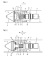
- the Fig. 1, 2 each show a schematic diagram of a non-return valve 1 according to an embodiment of the invention.
- the non-return valve 1 is located in a state installed in an injection molding machine indicated by corresponding walls 2 of a worm cylinder for injection molding of thermoplastic plastics materials.
- FIG. 1 shown representation corresponds to the closed position of the backflow valve 1
- FIG. 2 The illustration shown corresponds to the open position of the backflow lock. 1
- the non-return valve 1 comprises as essential components a rotationally symmetrical, substantially cylindrical base body 3, a relative to the base body 3 movably mounted biconical closing body 4 and the closing body 4 associated adjusting device. 5
- the main body 3 is provided with a plurality of these each passing through melt channels 6.
- the melt channels 6 extend in each case between respective melt channel inlet openings 6a formed in the right-hand region of the main body 3 and in the melt channel outlet openings 6b formed in the left-hand region of the main body 3 in the figures.
- the main body 3 is also centrally, ie provided in the region of the axis of symmetry A, with an axial through hole 7.
- the through hole 7 has areas 7a, 7b, 7c of different diameter.
- the diameter of the portion 7a is smaller than the diameter of the portion 7b axially thereafter, and the diameter of the portion 7b is smaller than the diameter of the portion 7c axially thereafter.
- a step 8 is formed between the region 7b of the mean diameter and the region 7c of the largest diameter.
- a counter-stop pin 9 is screwed, whose in the base body 3, d. H. in the base-side through hole 7, projecting free end in the right side of the through hole 7 closes.
- associated bolt 10 projects in the areas 7a, 7b of the through hole 7 of the adjusting device 5 associated bolt 10 projects.
- the bolt 10 is axially movable in the through hole 7 of the base body 3 relative to the base body 3, d. H. axially displaceable, guided.
- the bolt 10 is in the region of its lying outside of the base body 3 free end with the closing body 4, z. B. by a screw connected.
- the bolt 10 thus coupled the closing body 4 with the base body 3.
- the immediate free end of lying within the body 3 bolt 10 is radially expanded according to the area 7c of the largest diameter of the base body-side through hole 7, so that here is a kind of piston-cylinder guide.
- actuating force F1 is exerted on the closing device 4 such that the closing body 4 is moved to the closed position or is (see. Fig. 1 ).
- the actuating force F1 essentially corresponds to the spring force of the compression spring 11 or is implemented by this. This results from the special arrangement of the compression spring 11 on the bolt 4 connected to the closing body 4, which allows the spring force of the compression spring 11 acts on the closing body 4, that this, if no spring force compensating further forces be exerted on the closing body 4, moved into the closed position and is held in the closed position or will.
- Fig. 1 In the closed position of the backflow lock 1, the closing body 4 is thus moved in front of the melt channel outlet openings 6b facing it such that an outlet of a plasticized melt flowing through the base body side melt channel 6 from the melt channel outlet openings 6b and therefore a flow of the plasticized melt in the Schneckenvorraum the injection molding machine is not possible.
- Fig. 1 Based on Fig. 1 is also apparent that the bolt 10 in the closed position of the return flow lock 1 with its one bolt-side first stop surface forming, the counter-stop pin 9 directly facing free end rests against a body-side first counter-stop.
- the base-body-side first counter-stop is formed by the projecting into the main body 3 free end of the counter-stop pin 9.
- the closing body 4 is moved away from the melt channel outlet openings 6b facing it in such a way that a discharge of a plasticized melt from the melt channel outlet openings 6b and therefore a flow of the plasticized melt into the screw antechamber of the injection molding machine is possible.
- Fig. 2 Based on Fig. 2 is also apparent that the bolt 10 rests in the open position of the return flow lock 1 with a second stop surface formed in the region of the free end on a body-side second counter-stop.
- the body-side second counter-attack is included formed by the between the areas 7b, 7c of the base-body-side through hole 7 formed step 8.
- the axial movement of the closing body 4, as well as the axial movement of the bolt 10 coupled thereto, between the in Fig. 1 shown closed position and in Fig. 2 shown opening position of the backflow valve 1 results from the fact that in the context of an injection molding, ie in particular an injection process, with high pressure through the main body side melt channel 6 flowing plasticized melt exerts a force F2 opposing the force F1 on the closing body 4.
- the force direction of the force exerted on the closing body 4 via the adjusting device 5 actuating force F1 is therefore contrary to the direction of force of the force F2, which is exerted by the flowing through the base-side melt channel 6 plasticized melt on the closing body 4.
- the force exerted on the closing body 4 via the adjusting device 5 actuating force F1 the force exerted on the closing body 4 via the adjusting device 5 actuating force F1, d. H. the spring force of the compression spring 11, chosen such that it is smaller than acting on the closing body 4 force F2 of the flowing in the context of an injection molding of the injection molding machine through the base-side melt channel 6 plasticized melt.
Landscapes
- Engineering & Computer Science (AREA)
- Manufacturing & Machinery (AREA)
- Mechanical Engineering (AREA)
- Injection Moulding Of Plastics Or The Like (AREA)
Abstract
Rückstromsperre (1) für eine Spritzgießmaschine wobei eine Stelleinrichtung (5) einen einen Schließkörper (4) mit einem Grundkörper (3) koppelnden, relativ zu dem Grundkörper (3) bewegbar gelagerten Bolzen (10) umfasst, wobei eine Druckfeder (11) auf einem innerhalb des Grundkörpers (3) befindlichen Bolzenabschnitt des Bolzens (10) angeordnet ist, wobei der Bolzen (10) im Bereich seines dem Schließkörper (4) abgewandten Endes mit einer Anschlagfläche versehen ist, mit welcher Anschlagfläche er in der Schließstellung an einem grundkörperseitigen ersten Gegenanschlag anliegt, und/oder dass der Bolzen (10) im Bereich seines dem Schließkörper (4) abgewandten Endes mit einer Anschlagfläche versehen ist, mit welcher Anschlagfläche er in der Öffnungsstellung an einem grundkörperseitigen zweiten Gegenanschlag anliegt.A backflow lock (1) for an injection molding machine, wherein an adjusting device (5) comprises a closure member (4) with a base body (3) coupling, relative to the base body (3) movably mounted bolt (10), wherein a compression spring (11) on a inside the base body (3) located bolt portion of the bolt (10) is arranged, wherein the bolt (10) in the region of the closing body (4) facing away from the end is provided with a stop surface, with which stop surface he in the closed position on a body side first counter-stop is applied, and / or that the bolt (10) is provided in the region of the closing body (4) facing away from the end with a stop surface, with which stop surface it rests in the open position on a body-side second counter-stop.
Description
Die Erfindung betrifft eine Rückstromsperre für eine Spritzgießmaschine, umfassend einen Grundkörper, in welchem wenigstens ein zwischen wenigstens einer grundkörperseitigen Schmelzekanaleintrittsöffnung und wenigstens einer grundkörperseitigen Schmelzekanalaustrittsöffnung verlaufender Schmelzekanal ausgebildet ist.The invention relates to a non-return valve for an injection molding machine, comprising a base body, in which at least one melt channel extending between at least one main body-side melt channel inlet opening and at least one melt channel outlet opening on the base side is formed.
Derartige Rückstromsperren sind an und für sich bekannt. Aufgabe und Funktion entsprechender Rückstromsperren bestehen im Allgemeinen darin, in ihrem in eine Spritzgießmaschine, typischerweise im Bereich einer Plastifiziereinheit zur Plastifizierung eines zu plastifizierenden Materials, verbauten Zustand ein Rückströmen von plastifiziertem Material von einem Schneckenvorraum, in welchem sich das plastifizierte Material vor dem Einspritzen in eine Kavität eines Spritzgießwerkzeugs befindet, in hintere Bereiche des Schneckenzylinders zu unterbinden.Such backflow barriers are known per se. The object and function of corresponding non-return valves generally consist in their installed in an injection molding machine, typically in the region of a plasticizing unit for plasticizing a material to be plasticized state, a backflow of plasticized material from a screw antechamber in which the plasticized material before injection into a Cavity of an injection mold is to prevent in the rear areas of the screw cylinder.
Konstruktiv umfassen entsprechende Rückstromsperren typischerweise einen von wenigstens einem Schmelzekanal durchsetzten Grundkörper. Ein Rückströmen von plastifiziertem Material kann prinzipiell dadurch verhindert werden, dass ein Schließkörper derart relativ zu dem Grundkörper bewegt wird, dass dieser eine entsprechende grundkörperseitige Schmelzekanalaustrittsöffnung verschließt.Constructively, corresponding backflow locks typically comprise a body penetrated by at least one melt channel. A return flow of plasticized material can in principle be prevented by moving a closing body relative to the base body in such a way that it closes off a corresponding melt-body outlet opening on the base body side.
Wenngleich aus dem Stand der Technik, insbesondere im Hinblick auf deren Dichtigkeit, technisch ausgereifte Prinzipien entsprechender Rückstromsperren bekannt sind, besteht weiterhin ein Bedarf an einer technisch zuverlässigen wie auch konstruktiv einfach aufgebauten Rückstromsperre.Although from the prior art, in particular with regard to their tightness, technically mature principles of corresponding backflow barriers are known, there is still a need for a technically reliable as well as structurally simple constructed backflow valve.
Der Erfindung liegt daher die Aufgabe zugrunde, eine technisch zuverlässige sowie konstruktiv einfach aufgebaute Rückstromsperre anzugeben.The invention is therefore based on the object of specifying a technically reliable and structurally simple constructed backflow lock.
Die Aufgabe wird durch eine Rückstromsperre der eingangs genannten Art gelöst, welche sich erfindungsgemäß durch einen relativ zu dem Grundkörper bewegbar gelagerten Schließkörper, welcher in einer Öffnungsstellung derart von der diesem zugewandten Schmelzekanalaustrittsöffnung weg bewegt ist, dass ein Austritt einer plastifizierten Schmelze aus der Schmelzekanalaustrittsöffnung möglich ist, und in einer Schließstellung derart vor die diesem zugewandte Schmelzekanalaustrittsöffnung bewegt ist, dass ein Austritt einer plastifizierten Schmelze aus der Schmelzekanalaustrittsöffnung nicht möglich ist, sowie eine dem Schließkörper zugeordnete Stelleinrichtung, über welche eine auf den Schließkörper wirkende Stellkraft derart ausübbar oder ausgeübt ist, dass der Schließkörper in die Schließstellung bewegt wird, auszeichnet.The object is achieved by a non-return valve of the type mentioned, which according to the invention by a movable relative to the base body mounted closing body, which in such an opening position is moved away from the melt channel outlet opening facing this, that an outlet of a plasticized melt from the melt channel outlet opening is possible, and in a closed position in front of this facing melt channel outlet opening is moved that an outlet of a plasticized melt from the Melting channel exit opening is not possible, as well as a closing body associated adjusting device, via which a force acting on the closing body actuating force is exerted or exercised in such a way that the closing body is moved into the closed position, characterized.
Die erfindungsgemäße Rückstromsperre umfasst als im Hinblick auf deren Funktionsprinzip wesentliche Komponenten einen Grundkörper, einen relativ zu dem Grundkörper bewegbar gelagerten, typischerweise mit dem Grundkörper gekoppelten, Schließkörper und eine dem Schließkörper zugeordnete Stelleinrichtung. Die erfindungsgemäße Rückstromsperre kann auch als Rückstromventil bezeichnet bzw. erachtet werden.The non-return valve according to the invention comprises, as essential components with regard to their functional principle, a base body, a closing body movably mounted relative to the base body, typically coupled to the base body, and an adjusting device associated with the closing body. The backflow lock according to the invention can also be referred to as a backflow valve or considered.
Der Grundkörper der Rückstromsperre ist derart bemessen, dass er in einen Schneckenzylinder einer mit der erfindungsgemäßen Rückstromsperre ausgestatteten Spritzgießmaschine einsetzbar ist. In dem Grundkörper ist wenigstens ein Schmelzekanal, d. h. eine den Grundkörper vollständig durchsetzende Bohrung oder Öffnung, durch welche eine plastifizierte Schmelze strömen kann, ausgebildet. Der Schmelzekanal verläuft zwischen einer Schmelzekanaleintrittsöffnung, über welche eine plastifizierte Schmelze in den Grundkörper eintreten kann, und einer Schmelzekanalaustrittsöffnung, über welche eine in den Grundkörper eingetretene plastifizierte Schmelze aus dem Grundkörper austreten kann. Die Schmelzekanaleintrittsöffnung und die Schmelzekanalaustrittsöffnung befinden sich typischerweise an entgegen gesetzten Enden des Grundkörpers.The main body of the non-return valve is dimensioned such that it can be inserted into a screw cylinder of an injection molding machine equipped with the non-return valve according to the invention. In the body is at least one melt channel, d. H. a body completely passing through the bore or opening through which a plasticized melt can flow formed. The melt channel extends between a melt channel inlet opening, via which a plasticized melt can enter the base body, and a melt channel outlet opening, via which a plasticized melt which has entered the base body can emerge from the base body. The melt channel inlet opening and the melt channel outlet opening are typically located at opposite ends of the body.
Der Schließkörper der Rückstromsperre ist relativ zu dem Grundkörper bewegbar gelagert. Der Schließkörper kann dabei insbesondere in bzw. zwischen zwei Stellungen, nämlich eine(r) Öffnungsstellung, in welcher der Schließkörper derart von der diesem zugewandten Schmelzekanalaustrittsöffnung weg bewegt ist, dass ein Austritt einer plastifizierten Schmelze aus der Schmelzekanalaustrittsöffnung möglich ist, und eine(r) Schließstellung, in welcher der Schließkörper derart vor die diesem zugewandte Schmelzekanalaustrittsöffnung bewegt ist, dass ein Austritt einer plastifizierten Schmelze aus der Schmelzekanalaustrittsöffnung nicht möglich ist, bewegt werden. Die Öffnungsstellung des Schließkörpers entspricht gleichermaßen der Öffnungsstellung der Rückstromsperre, die Schließstellung des Schließkörpers entspricht gleichermaßen der Schließstellung der Rückstromsperre.The closing body of the non-return valve is movably mounted relative to the main body. The closing body can in particular in or between two positions, namely a (r) opening position, in which the closing body in such a way is moved away from the melt channel outlet opening facing this, that a discharge of a plasticized melt from the melt channel outlet opening is possible, and a (r) closed position, in which the closing body is moved in front of the facing this melt channel outlet opening, that an outlet of a plasticized melt from the melt channel outlet opening is not possible to be moved. The open position of the closing body also corresponds to the open position of the return flow lock, the closed position of the closing body also corresponds to the closed position of the return flow lock.
Im in einer Spritzgießmaschine verbauten Zustand der Rückstromsperre ist der Grundkörper typischerweise lagefest, d. h. unbewegbar, innerhalb des Schneckenzylinders der Spritzgießmaschine gelagert, der Schließkörper ist relativ zu dem Grundkörper bewegbar gelagert. Die Aufgabe bzw. Funktion der Rückstromsperre wird also insbesondere dadurch erfüllt, dass in der Öffnungsstellung des Schließkörpers ein Strömen von plastifizierter Schmelze durch den Grundkörper, d. h. von einem bezogen auf eine Einspritzeinheit der Spritzgießmaschine hinteren Bereich des Schneckenzylinders in einen Schneckenvorraum, möglich ist, wohingegen in der Schließstellung des Schließkörpers ein Rückströmen von in dem Schneckenvorraum befindlicher plastifizierter Schmelze zumindest weitgehend verhindert ist.In installed in an injection molding machine state of the return flow block the body is typically fixed in position, d. H. unmovable stored within the screw cylinder of the injection molding machine, the closing body is mounted relative to the movable body. The task or function of the return flow block is thus in particular satisfied that in the open position of the closing body, a flow of plasticized melt through the body, d. H. from a relative to an injection unit of the injection molding machine rear portion of the screw cylinder in a screw antechamber, is possible, whereas in the closed position of the closing body, a return flow of located in the screw cavity plasticized melt is at least largely prevented.
Die Rückstromsperre umfasst eine dem Schließkörper zugeordnete Stelleinrichtung, über welche eine auf den Schließkörper wirkende Stellkraft derart ausübbar oder ausgeübt ist, dass der Schließkörper in die Schließstellung bewegt wird. Die Stelleinrichtung ist also dazu eingerichtet, eine auf den Schließkörper wirkende Stellkraft derart auszuüben, dass der Schließkörper in die Schließstellung bewegt wird. Bedingt durch die über die Stelleinrichtung auf den Schließkörper ausgeübte Stellkraft, wird der Schließkörper also, sofern keine die Stellkraft kompensierende Kraft auf diesen ausgeübt wird, in die Schließstellung bewegt bzw. in dieser gehalten oder gesichert. Über eine die Stellkraft kompensierende Kraft ist es sonach möglich, die Wirkung der durch die über die Stelleinrichtung auf den Schließkörper ausgeübten Stellkraft aufzuheben und den Schließkörper aus der Schließstellung zu lösen, d. h. insbesondere in von der Schließstellung in die Öffnungsstellung zu überführen.The non-return valve comprises an actuating device associated with the closing body, via which an actuating force acting on the closing body can be exerted or exerted in such a way that the closing body is moved into the closed position. The adjusting device is thus adapted to exert a force acting on the closing body actuating force such that the closing body is moved into the closed position. Due to the force exerted on the closing body via the adjusting device actuating force, the closing body is thus, if no force compensating the adjusting force is exerted on this, moved into the closed position or held or secured in this. About a force compensating for the force, it is therefore possible to cancel the effect of the force exerted on the closing body via the adjusting force and the To release closing body from the closed position, ie in particular to convert from the closed position to the open position.
Wie sich im Weiteren noch ergibt, ist eine die Stellkraft kompensierende Kraft typischerweise eine im Rahmen eines Spritzgießvorgangs, d. h. insbesondere Einspritzvorgangs, durch eine durch den Grundkörper strömende plastifizierte Schmelze auf den Schließkörper ausgeübte Kraft. Die durch eine durch den Grundkörper strömende plastifizierte Schmelze auf den Schließkörper ausgeübte Kraft ist dabei insbesondere abhängig von dem Druck, d. h. insbesondere dem Einspritzdruck, mit welchem die plastifizierte Masse im Rahmen des Spritzgießvorgangs, d. h. insbesondere des Einspritzvorgangs, durch den Grundkörper strömt.As will be seen below, a force compensating for the force is typically one in the context of an injection molding operation, i. H. in particular injection process, by a force flowing through the body plastified melt on the closing body force exerted. The force exerted on the closing body by a plasticized melt flowing through the base body is in particular dependent on the pressure, ie. H. in particular the injection pressure with which the plasticized mass in the injection molding process, d. H. in particular of the injection process, flows through the body.
Hieraus lässt sich folgern, dass die Kraftrichtung der über die Stelleinrichtung ausgeübten Stellkraft typischerweise entgegen gesetzt der Kraftrichtung einer Kraft, welche im in einer Spritzgießmaschine verbauten Zustand der Rückstromsperre durch eine durch den grundkörperseitigen Schmelzekanal strömende plastifizierte Schmelze auf Schließkörper ausgeübt wird, ist.It can be concluded from this that the force direction of the actuating force exerted on the adjusting device is typically opposite to the direction of force of a force which is exerted on closing body in the installed in an injection molding machine state of the return flow block through a plasticized melt flowing through the main body side melt channel.
Hieraus lässt sich ebenso folgern, dass die über die Stelleinrichtung ausgeübte Kraft zweckmäßig derart gewählt ist, dass sie kleiner als eine auf den Schließkörper wirkende Kraft einer im Rahmen eines Spritzgießvorgangs einer Spritzgießmaschine, in welcher die Rückstromsperre verbaut ist, durch den grundkörperseitigen Schmelzekanal strömenden plastifizierten Schmelze ist.It can also be concluded from this that the force exerted on the adjusting device is expediently chosen such that it is smaller than a force acting on the closing body force of a plasticized melt flowing through the main body side melt channel as part of an injection molding of an injection molding machine, in which the return flow block is installed is.
In einer bevorzugten Ausführungsform der erfindungsgemäßen Rückstromsperre umfasst die Stelleinrichtung wenigstens eine innerhalb des Grundkörpers angeordnete, mit dem Schließkörper gekoppelte Druckfeder, über welche die auf den Schließkörper wirkende Stellkraft ausgeübt ist bzw. wird. Bevorzugt ist also wenigstens eine mit dem Schließkörper gekoppelte Druckfeder vorgesehen, welche wenigstens eine Druckfeder innerhalb des Grundkörpers derart angeordnet bzw. ausgerichtet ist, dass die über diese ausgeübte Federkraft bedingt durch ihre Kopplung mit dem Schließkörper derart auf den Schließkörper wirkt, dass dieser in die Schließstellung bewegt bzw. in der Schließstellung gehalten wird. Die Kopplung zwischen der Druckfeder und dem Schließkörper ist typischerweise mittelbar, d. h. unter Zwischenschaltung wenigstens eines weiteren Bauteils, realisiert.In a preferred embodiment of the non-return valve according to the invention, the adjusting device comprises at least one pressure spring, which is arranged within the main body and coupled to the closing body, via which the actuating force acting on the closing body is or will be exerted. Preferably, therefore, at least one coupled to the closing body compression spring is provided, which is at least one compression spring disposed or aligned within the body in such a way that the spring force exerted on them due to their coupling with the closing body on the closing body acts, that this moves into the closed position and is held in the closed position. The coupling between the compression spring and the closing body is typically realized indirectly, ie with the interposition of at least one further component.
Dementsprechend kann es in Weiterbildung dieser bevorzugten Ausführungsform der erfindungsgemäßen Rückstromsperre vorgesehen sein, dass die Stelleinrichtung einen den Schließkörper mit dem Grundkörper koppelnden, relativ zu dem Grundkörper bewegbar gelagerten Bolzen umfasst, wobei die Druckfeder auf einem innerhalb des Grundkörpers befindlichen Bolzenabschnitt des Bolzens angeordnet ist. Der der Stelleinrichtung zugehörige Bolzen dient also einerseits dazu, den Schließkörper mit dem Grundkörper zu koppeln, d. h. eine physikalischmechanische Verbindung zwischen dem Schließkörper und dem Grundkörper herzustellen. Der der Stelleinrichtung zugehörige Bolzen dient über einen innerhalb des Grundkörpers befindlichen Bolzenabschnitt andererseits dazu, die der Stelleinrichtung ebenso zugehörige Druckfeder innerhalb des Grundkörpers zu lagern. Hieraus ergibt sich, dass über den Bolzen auch die vorstehend beschriebene mittelbare Kopplung zwischen der Druckfeder und dem Schließkörper realisiert sein kann.Accordingly, it may be provided in a development of this preferred embodiment of the backflow lock according to the invention that the actuating device comprises a closing body with the body coupling, relative to the base body movably mounted bolt, wherein the compression spring is disposed on a located within the body bolt portion of the bolt. The actuator associated bolt thus serves on the one hand to couple the closing body with the body, d. H. to produce a physical-mechanical connection between the closing body and the base body. On the other hand, the bolt associated with the adjusting device serves to support the compression spring, which is likewise associated with the adjusting device, within the basic body via a bolt section located inside the main body. It follows that the above-described indirect coupling between the compression spring and the closing body can be realized via the bolt.
Der Bolzen ragt typischerweise zumindest mit seinem dem Schließkörper abgewandten Ende abschnittsweise in eine grundkörperseitige Bohrung, insbesondere eine Sack- oder Durchgangsbohrung. Der Grundkörper ist sonach, insbesondere zur Aufnahme bzw. Lagerung des Bolzens, mit einer Bohrung versehen, in welche der Bolzen derart ragt, dass ein erster oder innerer Bolzenabschnitt innerhalb des Grundkörpers befindlich und ein zweiter oder äußerer Bolzenabschnitt außerhalb des Grundkörpers befindlich ist. Über den ersten oder inneren Bolzenabschnitt erfolgt die Lagerung der Druckfeder, über den zweiten oder äußeren Bolzenabschnitt erfolgt die Kopplung mit dem Schließkörper, d. h. der Schließkörper ist mit dem zweiten oder äußeren Bolzenabschnitt gekoppelt respektive an diesem angeordnet.The bolt typically projects at least with its end facing away from the closing body in sections in a body-side bore, in particular a blind or through hole. The main body is thus, in particular for receiving or supporting the bolt, provided with a bore into which the bolt protrudes such that a first or inner bolt portion located within the body and a second or outer bolt portion is located outside the body. About the first or inner pin portion, the bearing of the compression spring, via the second or outer pin portion, the coupling is carried out with the closing body, ie, the closing body is coupled to the second or outer pin portion respectively arranged on this.
Der Bolzen kann im Bereich seines dem Schließkörper abgewandten Endes mit einer ersten Anschlagfläche versehen sein, mit welcher ersten Anschlagfläche er in der Schließstellung an einem grundkörperseitigen ersten Gegenanschlag anliegt. Durch die Ausbildung bzw. das Zusammenwirken entsprechender erster Anschlag- und Gegenanschlagflächen ist eine eindeutige Definition der Schließstellung realisierbar; diese liegt also vor, wenn die bolzenseitige erste Anschlagfläche an dem grundkörperseitigen ersten Gegenanschlag anliegt. Selbstverständlich kann im Hinblick auf fertigungsbedingte Toleranzen zwischen der bolzenseitigen ersten Anschlagfläche und dem grundkörperseitigen Gegenanschlag in der Schließstellung der Rückstromsperre auch ein gewisses Spiel gegeben sein.The bolt may be provided in the region of its end facing away from the closing body with a first stop surface, with which first stop surface it rests in the closed position on a main body side first counter-stop. By forming or the interaction of corresponding first stop and counter stop surfaces a clear definition of the closed position can be realized; This is therefore present when the bolt-side first stop surface bears against the base-body-side first counter-stop. Of course, with regard to production-related tolerances between the bolt-side first stop surface and the base-body-side counter-stop in the closed position of the backflow lock also be given a certain amount of play.
Der grundkörperseitige erste Gegenanschlag kann, sofern es sich bei der in dem Grundkörper vorgesehenen Bohrung um eine Sackbohrung handelt, beispielsweise durch eine Wand des Grundkörpers gebildet sein. Sofern es sich bei der in dem Grundkörper vorgesehenen Bohrung um eine Durchgangsbohrung handelt, kann der grundkörperseitige erste Gegenanschlag durch ein in den Grundkörper ragendes freies Ende eines mit dem Grundkörper verbundenen, insbesondere verschraubten, Gegenanschlagbolzens gebildet sein.If the bore provided in the base body is a blind bore, the base-body-side first counterstop can be formed, for example, by a wall of the base body. If the bore provided in the main body is a through-bore, the base-side first counter-stop can be formed by a free end of a counterpart stop pin connected to the main body, in particular screwed.
Der Bolzen kann im Bereich seines dem Schließkörper abgewandten Endes mit einer zweiten Anschlagfläche versehen sein, mit welcher zweiten Anschlagfläche er in der Öffnungsstellung an einem grundkörperseitigen zweiten Gegenanschlag anliegt. Durch die Ausbildung bzw. das Zusammenwirken entsprechender zweiter Anschlag- und Gegenanschlagflächen ist sonach eine eindeutige Definition der Öffnungsstellung realisierbar; diese liegt also vor, wenn die bolzenseitige zweite Anschlagfläche an dem grundkörperseitigen zweiten Gegenanschlag anliegt.The bolt may be provided in the region of its end facing away from the closing body with a second stop surface, with which second stop surface it rests in the open position on a body-side second counter-stop. By training or the interaction of corresponding second stop and counter stop surfaces is therefore a clear definition of the open position feasible; This is therefore present when the bolt-side second stop surface bears against the base-body-side second counter-stop.
Der grundkörperseitige zweite Gegenanschlag kann beispielsweise durch eine in der grundkörperseitigen Bohrung gebildete radiale Stufe, d. h. im Bereich einer Änderung des Bohrungsdurchmessers, gebildet sein.The base-body-side second counter-stop can be formed, for example, by a radial step formed in the base-body-side bore, ie in the region of a change in the bore diameter.
Die Erfindung betrifft ferner eine Spritzgießmaschine, insbesondere zum Spritzgießen von thermoplastischen Kunststoffmaterialien, aufweisend wenigstens eine wie vorstehend beschriebene erfindungsgemäße Rückstromsperre.The invention further relates to an injection molding machine, in particular for injection molding of thermoplastic plastics materials, comprising at least one backflow barrier according to the invention as described above.
Mithin gelten sämtliche obigen Ausführungen im Zusammenhang mit der erfindungsgemäßen Rückstromsperre analog für die erfindungsgemäße Spritzgießmaschine.Consequently, all the above explanations in connection with the non-return valve according to the invention apply analogously to the injection molding machine according to the invention.
Es soll im Zusammenhang mit der erfindungsgemäßen Spritzgießmaschine nochmals gesondert erwähnt werden, dass die über die Stelleinrichtung auf den Schließkörper ausgeübte Stellkraft zweckmäßig derart gewählt ist, dass sie kleiner als eine auf den Schließkörper wirkende Kraft einer im Rahmen eines Spritzgießvorgangs der Spritzgießmaschine durch den wenigstens einen grundkörperseitigen Schmelzekanal strömenden plastifizierten Schmelze ist. Über die auf den Schließkörper im Rahmen eines Spritzgießvorgangs der Spritzgießmaschine durch die durch den grundkörperseitigen Schmelzekanal strömende plastifizierte Schmelze wirkende Kraft ist die über die Stelleinrichtung ausgeübte Stellkraft sonach kompensierbar.It should be mentioned again separately in connection with the injection molding machine according to the invention that the force exerted on the actuator on the closing body actuating force is suitably selected such that it is less than a force acting on the closing body force of an injection molding of the injection molding machine by the at least one body side Melting channel flowing plasticized melt is. On the force acting on the closing body in the context of an injection molding of the injection molding machine through the plasticized melt flowing through the main body side melt channel force is exerted on the actuating force exerted on the adjusting device accordingly compensated.
Entsprechend erfolgt bei einem Strömen einer plastifizierten Schmelze durch den grundkörperseitigen Schmelzekanal im Rahmen eines Spritzgießvorgangs bzw. Einspritzvorgangs eine automatische Überführung des Schließkörpers von der Schließstellung in die Öffnungsstellung und somit ein Öffnen der Rückstromsperre. Sobald der Druck der durch den grundkörperseitigen Schmelzekanal strömenden plastifizierten Schmelze und somit die über diese auf den Schließkörper ausgeübte Kraft derart nachlässt, dass die über die Stelleinrichtung auf den Schließkörper ausgeübte Stellkraft überwiegt, wird der Schließkörper wieder von der Öffnungsstellung in die Schließstellung überführt, was ein Schließen der Rückstromsperre bedingt.Accordingly, during a flow of a plasticized melt through the base-body-side melt channel in the context of an injection molding or injection process, an automatic transfer of the closing body from the closed position to the open position and thus opening the return flow block. As soon as the pressure of the plasticized melt flowing through the base-body-side melt channel and thus the force exerted on it by the closing body decreases such that the actuating force exerted on the closing body via the adjusting device predominates, the closing body is again transferred from the open position to the closed position, which is a Closing the return flow stop conditionally.
Weitere Vorteile, Merkmale und Einzelheiten der Erfindung ergeben sich aus dem im Folgenden beschriebenen Ausführungsbeispiel sowie anhand der Zeichnungen. Dabei zeigen:
- Fig. 1, 2
- jeweils eine Prinzipdarstellung einer Rückstromsperre gemäß einem Ausführungsbeispiel der Erfindung.
- Fig. 1, 2
- in each case a schematic representation of a return flow block according to an embodiment of the invention.
Die
Die in
Die Rückstromsperre 1 umfasst als wesentliche Komponenten einen rotationssymmetrischen, im Wesentlichen zylindrischen Grundkörper 3, einen relativ zu dem Grundkörper 3 bewegbar gelagerten doppelkegelförmigen Schließkörper 4 und eine dem Schließkörper 4 zugeordnete Stelleinrichtung 5.The
Der Grundkörper 3 ist mit mehreren, diesen jeweils durchsetzenden Schmelzekanälen 6 versehen. Die Schmelzekanäle 6 erstrecken sich jeweils zwischen jeweiligen in den in den Fig. rechten Bereich des Grundkörpers 3 gebildeten Schmelzekanaleintrittsöffnungen 6a und in den in den Fig. im linken Bereich des Grundkörpers 3 gebildeten Schmelzekanalaustrittsöffnungen 6b.The
Der Grundkörper 3 ist zudem mittig, d. h. im Bereich der Symmetrieachse A, mit einer axialen Durchgangsbohrung 7 versehen. Die Durchgangsbohrung 7 weist Bereiche 7a, 7b, 7c unterschiedlicher Durchmesser auf. Der Durchmesser des Bereichs 7a ist kleiner als der Durchmesser des diesem axial folgenden Bereichs 7b, der Durchmesser des Bereichs 7b ist kleiner als der Durchmesser des diesem axial folgenden Bereichs 7c. Zwischen dem Bereich 7b des mittleren Durchmessers und dem Bereich 7c des größten Durchmessers ist eine Stufe 8 gebildet.The
In den Bereich 7c der Durchgangsbohrung 7 ist ein Gegenanschlagbolzen 9 eingeschraubt, dessen in den Grundkörper 3, d. h. in die grundkörperseitige Durchgangsbohrung 7, ragendes freies Ende die in den Fig. rechte Seite der Durchgangsbohrung 7 verschließt.In the
In die Bereiche 7a, 7b der Durchgangsbohrung 7 ragt ein der Stelleinrichtung 5 zugehöriger Bolzen 10. Der Bolzen 10 ist in der Durchgangsbohrung 7 des Grundkörpers 3 relativ zu dem Grundkörper 3 axial bewegbar, d. h. axial verschiebbar, geführt.In the
Der Bolzen 10 ist im Bereich seines außerhalb des Grundkörpers 3 liegenden freien Endes mit dem Schließkörper 4, z. B. durch eine Schraubverbindung, verbunden. Der Bolzen 10 koppelt sonach den Schließkörper 4 mit dem Grundkörper 3. In dem Bereich seines innerhalb des Grundkörpers 3 liegenden freien Endes ist auf dem Bolzen 10 eine der Stelleinrichtung 5 ebenso zugehörige Druckfeder 11 angeordnet. Das unmittelbare freie Ende des innerhalb des Grundkörpers 3 liegenden Bolzens 10 ist entsprechend dem Bereich 7c des größten Durchmessers der grundkörperseitigen Durchgangsbohrung 7 radial aufgeweitet, so dass sich hier eine Art Kolben-Zylinder-Führung ergibt.The
Im Weiteren wird das Funktionsprinzip der Rückstromsperre 1, d. h. insbesondere das Funktionsprinzip der dieser zugehörigen Stelleinrichtung 5, näher erläutert.In the following, the operating principle of the
Wie durch den Pfeil F1 angedeutet, ist bzw. wird über die Stelleinrichtung 5 eine auf den Schließkörper 4 wirkende Stellkraft F1 derart ausgeübt, dass der Schließkörper 4 in die Schließstellung bewegt ist bzw. wird (vgl.
Wie erwähnt, zeigt
Anhand von
In der in
Anhand von
Die axiale Bewegung des Schließkörpers 4, wie auch die axiale Bewegung des mit diesem gekoppelten Bolzens 10, zwischen der in
Um die durch die Stelleinrichtung 5 auf den Schließkörper 4 ausgeübte Stellkraft F1 zu kompensieren, ist die über die Stelleinrichtung 5 auf den Schließkörper 4 ausgeübte Stellkraft F1, d. h. die Federkraft der Druckfeder 11, derart gewählt, dass sie kleiner als eine auf den Schließkörper 4 wirkende Kraft F2 der im Rahmen eines Spritzgießvorgangs der Spritzgießmaschine durch den grundkörperseitigen Schmelzekanal 6 strömenden plastifizierten Schmelze ist.To compensate for the force exerted by the adjusting
Entsprechend erfolgt bei einem Strömen einer plastifizierten Schmelze im Rahmen eines Spritzgießvorgangs durch den Grundkörper 3 eine automatische Überführung des Schließkörpers 4 von der in
Claims (8)
der Bolzen (10) im Bereich seines dem Schließkörper (4) abgewandten Endes mit einer Anschlagfläche versehen ist, mit welcher Anschlagfläche er in der Schließstellung an einem grundkörperseitigen ersten Gegenanschlag anliegt, und/oder
dass der Bolzen (10) im Bereich seines dem Schließkörper (4) abgewandten Endes mit einer Anschlagfläche versehen ist, mit welcher Anschlagfläche er in der Öffnungsstellung an einem grundkörperseitigen zweiten Gegenanschlag anliegt.Backflow lock (1) for an injection molding machine, comprising:
the bolt (10) in the region of its end facing away from the closing body (4) is provided with a stop surface, with which stop surface it rests in the closed position against a base-side first counter-stop, and / or
that the bolt (10) is provided in the region of its end facing away from the closing body (4) with a stop surface, with which stop surface it rests in the open position on a body-side second counter-stop.
Applications Claiming Priority (1)
| Application Number | Priority Date | Filing Date | Title |
|---|---|---|---|
| DE102013114125.0A DE102013114125B4 (en) | 2013-12-16 | 2013-12-16 | Backflow lock for an injection molding machine |
Publications (2)
| Publication Number | Publication Date |
|---|---|
| EP2883677A1 true EP2883677A1 (en) | 2015-06-17 |
| EP2883677B1 EP2883677B1 (en) | 2017-05-03 |
Family
ID=51659545
Family Applications (1)
| Application Number | Title | Priority Date | Filing Date |
|---|---|---|---|
| EP14187518.7A Active EP2883677B1 (en) | 2013-12-16 | 2014-10-02 | Non-return valve for an injection moulding machine |
Country Status (2)
| Country | Link |
|---|---|
| EP (1) | EP2883677B1 (en) |
| DE (1) | DE102013114125B4 (en) |
Citations (3)
| Publication number | Priority date | Publication date | Assignee | Title |
|---|---|---|---|---|
| GB2219236A (en) * | 1988-05-19 | 1989-12-06 | Tse Kwai Sum | Injection nozzle |
| US5164207A (en) * | 1991-11-08 | 1992-11-17 | Spirex Corporation | Plastic extruder with automatic shut-off valve |
| JPH0716892A (en) * | 1993-07-01 | 1995-01-20 | Yamashiro Seiki Seisakusho:Kk | Injection molding machine |
Family Cites Families (1)
| Publication number | Priority date | Publication date | Assignee | Title |
|---|---|---|---|---|
| US5441400A (en) * | 1994-04-07 | 1995-08-15 | Zeiger; Donald J. | Spring biased check valve for an injection molding machine |
-
2013
- 2013-12-16 DE DE102013114125.0A patent/DE102013114125B4/en active Active
-
2014
- 2014-10-02 EP EP14187518.7A patent/EP2883677B1/en active Active
Patent Citations (3)
| Publication number | Priority date | Publication date | Assignee | Title |
|---|---|---|---|---|
| GB2219236A (en) * | 1988-05-19 | 1989-12-06 | Tse Kwai Sum | Injection nozzle |
| US5164207A (en) * | 1991-11-08 | 1992-11-17 | Spirex Corporation | Plastic extruder with automatic shut-off valve |
| JPH0716892A (en) * | 1993-07-01 | 1995-01-20 | Yamashiro Seiki Seisakusho:Kk | Injection molding machine |
Also Published As
| Publication number | Publication date |
|---|---|
| DE102013114125B4 (en) | 2017-01-26 |
| DE102013114125A1 (en) | 2014-11-13 |
| EP2883677B1 (en) | 2017-05-03 |
Similar Documents
| Publication | Publication Date | Title |
|---|---|---|
| EP1712341B1 (en) | Injection nozzle with two outlet orifices | |
| DE2603891C3 (en) | Drive for moving an injection piston of a die casting machine | |
| DE2728820C3 (en) | Shut-off nozzle for a plastic injection molding machine | |
| WO1999006659A1 (en) | Door drive system | |
| DE60108956T2 (en) | ACTUATING PISTON WITH TWO SURFACES | |
| EP1494844B1 (en) | Hydraulic device for back and forth displacement of a machine piece and a closing unit on an injection moulding machine fitted with such a hydraulic device | |
| DE102010008167B4 (en) | Gate valve of a door operator | |
| DE102004015879A1 (en) | Injection molding system comprises injection molding machine, manifold, and anti-drool mechanism having melt passage, fixed pin, and actuated shut-off collar | |
| DE4002747C3 (en) | Electro-hydraulic drive unit | |
| EP2730822A2 (en) | Control valve for the regulation of a hydraulic volume flow | |
| EP2883677B1 (en) | Non-return valve for an injection moulding machine | |
| DE3406644C2 (en) | ||
| EP1293633A2 (en) | Door closer | |
| EP3240665A1 (en) | Hole former for use in injection molds | |
| EP1814708A1 (en) | Plasticizing and injecting device | |
| WO2013013925A2 (en) | Injection head and ejector of an injection device | |
| DE102009014567A1 (en) | casting tool | |
| EP1247931B1 (en) | Closure sequence controller | |
| DE102018210296B4 (en) | Drive for a door or window sash | |
| DE102018210277B4 (en) | Valve | |
| DE102005015420B4 (en) | Working cylinder with cushioning | |
| DE10107782B4 (en) | Door coordinator | |
| EP2913469B1 (en) | Control of the closure sequence for a door with a fixed wing and a moving wing | |
| DE102011000408A1 (en) | Intrusion mold for forming casting from plasticized mixed plastic obtained during plastic-recycling, has opening mechanism closing mold with front side in end position, and releasing mold in another end position for removal of casting | |
| DE102009004500A1 (en) | Door arrangement is provided with fixed leaf and moving leaf, where locking device is provided to block closing of moving leaf |
Legal Events
| Date | Code | Title | Description |
|---|---|---|---|
| PUAI | Public reference made under article 153(3) epc to a published international application that has entered the european phase |
Free format text: ORIGINAL CODE: 0009012 |
|
| 17P | Request for examination filed |
Effective date: 20141002 |
|
| AK | Designated contracting states |
Kind code of ref document: A1 Designated state(s): AL AT BE BG CH CY CZ DE DK EE ES FI FR GB GR HR HU IE IS IT LI LT LU LV MC MK MT NL NO PL PT RO RS SE SI SK SM TR |
|
| AX | Request for extension of the european patent |
Extension state: BA ME |
|
| R17P | Request for examination filed (corrected) |
Effective date: 20151012 |
|
| RBV | Designated contracting states (corrected) |
Designated state(s): AL AT BE BG CH CY CZ DE DK EE ES FI FR GB GR HR HU IE IS IT LI LT LU LV MC MK MT NL NO PL PT RO RS SE SI SK SM TR |
|
| GRAP | Despatch of communication of intention to grant a patent |
Free format text: ORIGINAL CODE: EPIDOSNIGR1 |
|
| INTG | Intention to grant announced |
Effective date: 20161215 |
|
| GRAS | Grant fee paid |
Free format text: ORIGINAL CODE: EPIDOSNIGR3 |
|
| GRAA | (expected) grant |
Free format text: ORIGINAL CODE: 0009210 |
|
| AK | Designated contracting states |
Kind code of ref document: B1 Designated state(s): AL AT BE BG CH CY CZ DE DK EE ES FI FR GB GR HR HU IE IS IT LI LT LU LV MC MK MT NL NO PL PT RO RS SE SI SK SM TR |
|
| REG | Reference to a national code |
Ref country code: GB Ref legal event code: FG4D Free format text: NOT ENGLISH |
|
| REG | Reference to a national code |
Ref country code: AT Ref legal event code: REF Ref document number: 889490 Country of ref document: AT Kind code of ref document: T Effective date: 20170515 Ref country code: CH Ref legal event code: EP |
|
| REG | Reference to a national code |
Ref country code: IE Ref legal event code: FG4D Free format text: LANGUAGE OF EP DOCUMENT: GERMAN |
|
| REG | Reference to a national code |
Ref country code: DE Ref legal event code: R096 Ref document number: 502014003629 Country of ref document: DE |
|
| REG | Reference to a national code |
Ref country code: NL Ref legal event code: MP Effective date: 20170503 |
|
| REG | Reference to a national code |
Ref country code: LT Ref legal event code: MG4D |
|
| PG25 | Lapsed in a contracting state [announced via postgrant information from national office to epo] |
Ref country code: LT Free format text: LAPSE BECAUSE OF FAILURE TO SUBMIT A TRANSLATION OF THE DESCRIPTION OR TO PAY THE FEE WITHIN THE PRESCRIBED TIME-LIMIT Effective date: 20170503 Ref country code: ES Free format text: LAPSE BECAUSE OF FAILURE TO SUBMIT A TRANSLATION OF THE DESCRIPTION OR TO PAY THE FEE WITHIN THE PRESCRIBED TIME-LIMIT Effective date: 20170503 Ref country code: NO Free format text: LAPSE BECAUSE OF FAILURE TO SUBMIT A TRANSLATION OF THE DESCRIPTION OR TO PAY THE FEE WITHIN THE PRESCRIBED TIME-LIMIT Effective date: 20170803 Ref country code: HR Free format text: LAPSE BECAUSE OF FAILURE TO SUBMIT A TRANSLATION OF THE DESCRIPTION OR TO PAY THE FEE WITHIN THE PRESCRIBED TIME-LIMIT Effective date: 20170503 Ref country code: FI Free format text: LAPSE BECAUSE OF FAILURE TO SUBMIT A TRANSLATION OF THE DESCRIPTION OR TO PAY THE FEE WITHIN THE PRESCRIBED TIME-LIMIT Effective date: 20170503 Ref country code: GR Free format text: LAPSE BECAUSE OF FAILURE TO SUBMIT A TRANSLATION OF THE DESCRIPTION OR TO PAY THE FEE WITHIN THE PRESCRIBED TIME-LIMIT Effective date: 20170804 |
|
| PG25 | Lapsed in a contracting state [announced via postgrant information from national office to epo] |
Ref country code: SE Free format text: LAPSE BECAUSE OF FAILURE TO SUBMIT A TRANSLATION OF THE DESCRIPTION OR TO PAY THE FEE WITHIN THE PRESCRIBED TIME-LIMIT Effective date: 20170503 Ref country code: BG Free format text: LAPSE BECAUSE OF FAILURE TO SUBMIT A TRANSLATION OF THE DESCRIPTION OR TO PAY THE FEE WITHIN THE PRESCRIBED TIME-LIMIT Effective date: 20170803 Ref country code: IS Free format text: LAPSE BECAUSE OF FAILURE TO SUBMIT A TRANSLATION OF THE DESCRIPTION OR TO PAY THE FEE WITHIN THE PRESCRIBED TIME-LIMIT Effective date: 20170903 Ref country code: NL Free format text: LAPSE BECAUSE OF FAILURE TO SUBMIT A TRANSLATION OF THE DESCRIPTION OR TO PAY THE FEE WITHIN THE PRESCRIBED TIME-LIMIT Effective date: 20170503 Ref country code: RS Free format text: LAPSE BECAUSE OF FAILURE TO SUBMIT A TRANSLATION OF THE DESCRIPTION OR TO PAY THE FEE WITHIN THE PRESCRIBED TIME-LIMIT Effective date: 20170503 Ref country code: PL Free format text: LAPSE BECAUSE OF FAILURE TO SUBMIT A TRANSLATION OF THE DESCRIPTION OR TO PAY THE FEE WITHIN THE PRESCRIBED TIME-LIMIT Effective date: 20170503 Ref country code: LV Free format text: LAPSE BECAUSE OF FAILURE TO SUBMIT A TRANSLATION OF THE DESCRIPTION OR TO PAY THE FEE WITHIN THE PRESCRIBED TIME-LIMIT Effective date: 20170503 |
|
| PG25 | Lapsed in a contracting state [announced via postgrant information from national office to epo] |
Ref country code: SK Free format text: LAPSE BECAUSE OF FAILURE TO SUBMIT A TRANSLATION OF THE DESCRIPTION OR TO PAY THE FEE WITHIN THE PRESCRIBED TIME-LIMIT Effective date: 20170503 Ref country code: CZ Free format text: LAPSE BECAUSE OF FAILURE TO SUBMIT A TRANSLATION OF THE DESCRIPTION OR TO PAY THE FEE WITHIN THE PRESCRIBED TIME-LIMIT Effective date: 20170503 Ref country code: EE Free format text: LAPSE BECAUSE OF FAILURE TO SUBMIT A TRANSLATION OF THE DESCRIPTION OR TO PAY THE FEE WITHIN THE PRESCRIBED TIME-LIMIT Effective date: 20170503 Ref country code: RO Free format text: LAPSE BECAUSE OF FAILURE TO SUBMIT A TRANSLATION OF THE DESCRIPTION OR TO PAY THE FEE WITHIN THE PRESCRIBED TIME-LIMIT Effective date: 20170503 Ref country code: DK Free format text: LAPSE BECAUSE OF FAILURE TO SUBMIT A TRANSLATION OF THE DESCRIPTION OR TO PAY THE FEE WITHIN THE PRESCRIBED TIME-LIMIT Effective date: 20170503 |
|
| REG | Reference to a national code |
Ref country code: DE Ref legal event code: R097 Ref document number: 502014003629 Country of ref document: DE |
|
| PG25 | Lapsed in a contracting state [announced via postgrant information from national office to epo] |
Ref country code: IT Free format text: LAPSE BECAUSE OF FAILURE TO SUBMIT A TRANSLATION OF THE DESCRIPTION OR TO PAY THE FEE WITHIN THE PRESCRIBED TIME-LIMIT Effective date: 20170503 Ref country code: SM Free format text: LAPSE BECAUSE OF FAILURE TO SUBMIT A TRANSLATION OF THE DESCRIPTION OR TO PAY THE FEE WITHIN THE PRESCRIBED TIME-LIMIT Effective date: 20170503 |
|
| PLBE | No opposition filed within time limit |
Free format text: ORIGINAL CODE: 0009261 |
|
| STAA | Information on the status of an ep patent application or granted ep patent |
Free format text: STATUS: NO OPPOSITION FILED WITHIN TIME LIMIT |
|
| 26N | No opposition filed |
Effective date: 20180206 |
|
| PG25 | Lapsed in a contracting state [announced via postgrant information from national office to epo] |
Ref country code: SI Free format text: LAPSE BECAUSE OF FAILURE TO SUBMIT A TRANSLATION OF THE DESCRIPTION OR TO PAY THE FEE WITHIN THE PRESCRIBED TIME-LIMIT Effective date: 20170503 Ref country code: MC Free format text: LAPSE BECAUSE OF FAILURE TO SUBMIT A TRANSLATION OF THE DESCRIPTION OR TO PAY THE FEE WITHIN THE PRESCRIBED TIME-LIMIT Effective date: 20170503 |
|
| REG | Reference to a national code |
Ref country code: CH Ref legal event code: PL |
|
| REG | Reference to a national code |
Ref country code: IE Ref legal event code: MM4A |
|
| REG | Reference to a national code |
Ref country code: FR Ref legal event code: ST Effective date: 20180629 |
|
| PG25 | Lapsed in a contracting state [announced via postgrant information from national office to epo] |
Ref country code: LU Free format text: LAPSE BECAUSE OF NON-PAYMENT OF DUE FEES Effective date: 20171002 Ref country code: LI Free format text: LAPSE BECAUSE OF NON-PAYMENT OF DUE FEES Effective date: 20171031 Ref country code: CH Free format text: LAPSE BECAUSE OF NON-PAYMENT OF DUE FEES Effective date: 20171031 |
|
| REG | Reference to a national code |
Ref country code: BE Ref legal event code: MM Effective date: 20171031 |
|
| PG25 | Lapsed in a contracting state [announced via postgrant information from national office to epo] |
Ref country code: BE Free format text: LAPSE BECAUSE OF NON-PAYMENT OF DUE FEES Effective date: 20171031 Ref country code: FR Free format text: LAPSE BECAUSE OF NON-PAYMENT OF DUE FEES Effective date: 20171031 |
|
| PG25 | Lapsed in a contracting state [announced via postgrant information from national office to epo] |
Ref country code: MT Free format text: LAPSE BECAUSE OF FAILURE TO SUBMIT A TRANSLATION OF THE DESCRIPTION OR TO PAY THE FEE WITHIN THE PRESCRIBED TIME-LIMIT Effective date: 20170503 |
|
| PG25 | Lapsed in a contracting state [announced via postgrant information from national office to epo] |
Ref country code: IE Free format text: LAPSE BECAUSE OF NON-PAYMENT OF DUE FEES Effective date: 20171002 |
|
| GBPC | Gb: european patent ceased through non-payment of renewal fee |
Effective date: 20181002 |
|
| PG25 | Lapsed in a contracting state [announced via postgrant information from national office to epo] |
Ref country code: HU Free format text: LAPSE BECAUSE OF FAILURE TO SUBMIT A TRANSLATION OF THE DESCRIPTION OR TO PAY THE FEE WITHIN THE PRESCRIBED TIME-LIMIT; INVALID AB INITIO Effective date: 20141002 |
|
| PG25 | Lapsed in a contracting state [announced via postgrant information from national office to epo] |
Ref country code: CY Free format text: LAPSE BECAUSE OF FAILURE TO SUBMIT A TRANSLATION OF THE DESCRIPTION OR TO PAY THE FEE WITHIN THE PRESCRIBED TIME-LIMIT Effective date: 20170503 Ref country code: GB Free format text: LAPSE BECAUSE OF NON-PAYMENT OF DUE FEES Effective date: 20181002 |
|
| PG25 | Lapsed in a contracting state [announced via postgrant information from national office to epo] |
Ref country code: MK Free format text: LAPSE BECAUSE OF FAILURE TO SUBMIT A TRANSLATION OF THE DESCRIPTION OR TO PAY THE FEE WITHIN THE PRESCRIBED TIME-LIMIT Effective date: 20170503 |
|
| PG25 | Lapsed in a contracting state [announced via postgrant information from national office to epo] |
Ref country code: TR Free format text: LAPSE BECAUSE OF FAILURE TO SUBMIT A TRANSLATION OF THE DESCRIPTION OR TO PAY THE FEE WITHIN THE PRESCRIBED TIME-LIMIT Effective date: 20170503 |
|
| PG25 | Lapsed in a contracting state [announced via postgrant information from national office to epo] |
Ref country code: PT Free format text: LAPSE BECAUSE OF FAILURE TO SUBMIT A TRANSLATION OF THE DESCRIPTION OR TO PAY THE FEE WITHIN THE PRESCRIBED TIME-LIMIT Effective date: 20170503 |
|
| PG25 | Lapsed in a contracting state [announced via postgrant information from national office to epo] |
Ref country code: AL Free format text: LAPSE BECAUSE OF FAILURE TO SUBMIT A TRANSLATION OF THE DESCRIPTION OR TO PAY THE FEE WITHIN THE PRESCRIBED TIME-LIMIT Effective date: 20170503 |
|
| REG | Reference to a national code |
Ref country code: AT Ref legal event code: MM01 Ref document number: 889490 Country of ref document: AT Kind code of ref document: T Effective date: 20191002 |
|
| PG25 | Lapsed in a contracting state [announced via postgrant information from national office to epo] |
Ref country code: AT Free format text: LAPSE BECAUSE OF NON-PAYMENT OF DUE FEES Effective date: 20191002 |
|
| P01 | Opt-out of the competence of the unified patent court (upc) registered |
Effective date: 20230425 |
|
| PGFP | Annual fee paid to national office [announced via postgrant information from national office to epo] |
Ref country code: DE Payment date: 20231020 Year of fee payment: 10 |