EP2883618A1 - Tuyère d'injecteur - Google Patents
Tuyère d'injecteur Download PDFInfo
- Publication number
- EP2883618A1 EP2883618A1 EP14191625.4A EP14191625A EP2883618A1 EP 2883618 A1 EP2883618 A1 EP 2883618A1 EP 14191625 A EP14191625 A EP 14191625A EP 2883618 A1 EP2883618 A1 EP 2883618A1
- Authority
- EP
- European Patent Office
- Prior art keywords
- injector
- liquid
- chamber
- section
- injector nozzle
- Prior art date
- Legal status (The legal status is an assumption and is not a legal conclusion. Google has not performed a legal analysis and makes no representation as to the accuracy of the status listed.)
- Granted
Links
- 239000007788 liquid Substances 0.000 claims abstract description 72
- 239000007921 spray Substances 0.000 claims description 2
- 239000011814 protection agent Substances 0.000 description 7
- 238000011161 development Methods 0.000 description 6
- 230000018109 developmental process Effects 0.000 description 6
- 239000000575 pesticide Substances 0.000 description 5
- 238000002347 injection Methods 0.000 description 4
- 239000007924 injection Substances 0.000 description 4
- 239000000203 mixture Substances 0.000 description 4
- 238000002474 experimental method Methods 0.000 description 3
- XLYOFNOQVPJJNP-UHFFFAOYSA-N water Substances O XLYOFNOQVPJJNP-UHFFFAOYSA-N 0.000 description 3
- 239000004094 surface-active agent Substances 0.000 description 2
- 230000007423 decrease Effects 0.000 description 1
- 238000005516 engineering process Methods 0.000 description 1
- 238000001746 injection moulding Methods 0.000 description 1
- 238000000034 method Methods 0.000 description 1
- 238000004513 sizing Methods 0.000 description 1
Images

Classifications
-
- A—HUMAN NECESSITIES
- A01—AGRICULTURE; FORESTRY; ANIMAL HUSBANDRY; HUNTING; TRAPPING; FISHING
- A01M—CATCHING, TRAPPING OR SCARING OF ANIMALS; APPARATUS FOR THE DESTRUCTION OF NOXIOUS ANIMALS OR NOXIOUS PLANTS
- A01M7/00—Special adaptations or arrangements of liquid-spraying apparatus for purposes covered by this subclass
- A01M7/005—Special arrangements or adaptations of the spraying or distributing parts, e.g. adaptations or mounting of the spray booms, mounting of the nozzles, protection shields
-
- B—PERFORMING OPERATIONS; TRANSPORTING
- B05—SPRAYING OR ATOMISING IN GENERAL; APPLYING FLUENT MATERIALS TO SURFACES, IN GENERAL
- B05B—SPRAYING APPARATUS; ATOMISING APPARATUS; NOZZLES
- B05B7/00—Spraying apparatus for discharge of liquids or other fluent materials from two or more sources, e.g. of liquid and air, of powder and gas
- B05B7/02—Spray pistols; Apparatus for discharge
- B05B7/04—Spray pistols; Apparatus for discharge with arrangements for mixing liquids or other fluent materials before discharge
- B05B7/0408—Spray pistols; Apparatus for discharge with arrangements for mixing liquids or other fluent materials before discharge with arrangements for mixing two or more liquids
-
- B—PERFORMING OPERATIONS; TRANSPORTING
- B05—SPRAYING OR ATOMISING IN GENERAL; APPLYING FLUENT MATERIALS TO SURFACES, IN GENERAL
- B05B—SPRAYING APPARATUS; ATOMISING APPARATUS; NOZZLES
- B05B7/00—Spraying apparatus for discharge of liquids or other fluent materials from two or more sources, e.g. of liquid and air, of powder and gas
- B05B7/24—Spraying apparatus for discharge of liquids or other fluent materials from two or more sources, e.g. of liquid and air, of powder and gas with means, e.g. a container, for supplying liquid or other fluent material to a discharge device
- B05B7/2402—Apparatus to be carried on or by a person, e.g. by hand; Apparatus comprising containers fixed to the discharge device
- B05B7/244—Apparatus to be carried on or by a person, e.g. by hand; Apparatus comprising containers fixed to the discharge device using carrying liquid for feeding, e.g. by suction, pressure or dissolution, a carried liquid from the container to the nozzle
- B05B7/2443—Apparatus to be carried on or by a person, e.g. by hand; Apparatus comprising containers fixed to the discharge device using carrying liquid for feeding, e.g. by suction, pressure or dissolution, a carried liquid from the container to the nozzle the carried liquid and the main stream of carrying liquid being brought together downstream of the container before discharge
-
- B—PERFORMING OPERATIONS; TRANSPORTING
- B05—SPRAYING OR ATOMISING IN GENERAL; APPLYING FLUENT MATERIALS TO SURFACES, IN GENERAL
- B05B—SPRAYING APPARATUS; ATOMISING APPARATUS; NOZZLES
- B05B15/00—Details of spraying plant or spraying apparatus not otherwise provided for; Accessories
- B05B15/14—Arrangements for preventing or controlling structural damage to spraying apparatus or its outlets, e.g. for breaking at desired places; Arrangements for handling or replacing damaged parts
- B05B15/16—Arrangements for preventing or controlling structural damage to spraying apparatus or its outlets, e.g. for breaking at desired places; Arrangements for handling or replacing damaged parts for preventing non-intended contact between spray heads or nozzles and foreign bodies, e.g. nozzle guards
Definitions
- the invention relates to an injector nozzle for sucking liquids, comprising an injector chamber, a liquid inlet opening for a first liquid under positive pressure, which opens into the injector chamber, and a liquid suction opening for a liquid to be sucked, which opens into the injector chamber.
- the invention also relates to a crop protection syringe with an injector nozzle according to the invention.
- Injector nozzles are known in principle and work on the so-called Venturi principle.
- a liquid jet enters an injector chamber, creates a vacuum in the injector chamber, and then entrains gas or air with it.
- the so-called water jet pump works.
- the extinguishing pistol has a container in which a surfactant is arranged.
- the extinguishing water absorbs the surfactant via the injector chamber in order to make the extinguishing pistol suitable for extinguishing fat burns.
- the invention is intended to provide an injector nozzle for sucking in liquids, with which a substantially constant mixing ratio between the first liquid and a liquid to be sucked is achieved even with changing pressure of the supplied first liquid.
- an injector nozzle for sucking liquids with the features of claim 1 is provided for this purpose.
- Advantageous developments of the invention are specified in the subclaims.
- an injector nozzle for sucking in liquids with an injector chamber, a liquid inlet opening for a first liquid under overpressure, which opens into the injector, and a diesstechniksansaugö réelle for a liquid to be aspirated, which opens into the injector, provided, wherein the injector starting from the liquid inlet opening a first, conically widening in the flow direction section and a second, conically widening in the flow direction section wherein the second conical portion adjoins the first conical portion and wherein the second conical portion has a larger cone angle than the first conical portion.
- the injector nozzle according to the invention is thus suitable for applications in crop protection and it is thereby possible to realize a crop protection syringe in which the crop protection agent is introduced directly to the nozzle without additional injection pumps or the like.
- the injector nozzle according to the invention therefore makes it possible to build a very simple and reliable working plant sprayer, which nevertheless allows a constant mixing ratio.
- the injector nozzle according to the invention can be used in portable crop protection syringes in which the carrier liquid is pressurized with a hand pump. If the carrier liquid container then teaches during the course of the injection process, and the pressure with which the carrier liquid enters the injector chamber also decreases. With the injector nozzle according to the invention, it is nevertheless possible to maintain a substantially constant mixing ratio between sucked liquid and the first liquid or carrier liquid under overpressure.
- the first section has a cone angle to the central longitudinal axis of the injector chamber in a range between 5 ° and 10 °.
- the second section has a cone angle to the central longitudinal axis of the injector chamber between 30 ° and 40 °.
- Such a cone angle of the second section also ensures a substantially constant mixing ratio between carrier liquid and liquid to be sucked.
- the Cone angles of the first and second sections are measured over the entire cross section of the cone. Measured to the central longitudinal axis of the injector, the respective cone angle is only half of the stated values.
- the first section in the flow direction has a length which is between 2 times and 4 times, in particular 3 times, the length of the second section.
- a mixing chamber is arranged downstream of the injector chamber.
- an outlet opening for an exiting spray jet originates from the mixing chamber.
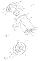
- FIG. 1 an injector nozzle 10 according to the invention is shown exploded.
- the injector nozzle has a housing 12 and an injector insert 14.
- the housing 12 is integrally formed, for example as a plastic injection molded part, and has an intake 16, to which a supply hose for liquid to be sucked can be attached.
- the housing 12 further has a nozzle mouthpiece 18 with a slot-shaped outlet opening 20.
- the injector nozzle 10 is designed through the slot-shaped outlet opening 20 as a flat jet nozzle.
- the shape and the dimension of the outlet opening 20 can be modified within the scope of the invention and, for example, the injector nozzle according to the invention can also be designed as a full-cone or hollow cone nozzle.
- the housing 12 has two lateral webs 22 which protrude slightly beyond the nozzle tip 18 and thereby protect it from damage.
- the injector insert 14 has a closure plate 24 which can be placed on a matching flange 26 on the housing 12 and the interior of the housing 12 apart from a in Fig. 1 thereby imperceptible inlet opening for pressurized carrier liquid thereby tightly closes.
- a closure plate 24 From the closure plate 24 is a cylinder 28, whose outer periphery is matched to the inner circumference of the housing 12 adjacent to the flange 26.
- the cylinder 28 thus ensures an exact fit of the Injektor horrins14 in the housing 12.
- the cylinder 28 has an approximately rectangular recess 30, of which a suction channel 32 in the direction of the in Fig. 1 Invisible injector chamber in the injector component 14 goes out. Via the recess 30 and the intake channel 32, liquid to be sucked can pass from the interior of the housing 12 and ultimately from the connection piece 16 into the injector chamber.
- a tubular nozzle 34 From the cylinder 28 is a tubular nozzle 34, which has a smaller diameter in a first portion 36 than in a second portion 38 which forms the free end of the tubular nozzle 34. Between the two sections 36, 38 an annular flange 40 is arranged with an even larger diameter than the second section 38.
- the first portion 36 does not come in contact with liquid but is therefore provided to provide a substantially constant wall thickness of the injector insert 14. This is particularly important when the Injektorbauteil 14 is formed as a plastic injection molded part.
- the circumferential annular flange 40 is formed as a circumferential seal and provides a reliable seal of a mixing and the discharge chamber in the housing 12.
- the second section 38 provides an orifice in the mixing and discharge chamber in the housing 12 is available.
- the carrier liquid is introduced under pressure into the injector 14, there enters the injector 42 and generates in the injector 42 a negative pressure, is sucked through the aspirated liquid, such as pesticides, through the intake passage 32.
- the aspirated crop protection agent and the carrier liquid then leave the injector and enter a mixing and discharge chamber in the housing 12 a. From the mixing and discharge chamber, the mixture of sucked liquid, especially pesticides, and carrier liquid then exits via the outlet opening 20 in the form of a flat jet.
- FIG. 2 shows the housing 12 in a view obliquely from above.
- the intake manifold 16 which opens into a channel 44 which ends in the assembled state of the injector 10 at the cuboid recess 30 in the cylinder 28 of the injector 14. Plant protection agent is thus sucked through the intake manifold 16, the channel 44, the recess 30 and the intake passage 32 and thereby passes into the injector 42.
- the mixing and discharge chamber 46 can be seen, which then merges into the outlet opening 20.
- FIG. 3 shows a side view of the injector 10 with the Injektorbauteil 14 and the housing 12th
- Fig. 4 shows a view on the cutting plane CC in Fig. 3 ,
- the inlet opening 50 for pressurized liquid can be seen at the injector insert 14.
- the injector chamber 42 which has a first section 52 and a second section 54, adjoins this inlet opening 50. Both the first portion 52 and the second portion 54 widen conically. Starting from the inlet opening 50, the injector chamber 42 expands to its end, where it merges into the mixing and outlet chamber 46.
- the mixing and discharge chamber 46 in turn has three sections, namely a first, cylindrical Section 56 and an adjoining, also cylindrical portion 58 with respect to the first portion 56 reduced diameter.
- a third section 60 has a significantly reduced diameter compared to the second section 58 and is likewise formed cylindrically with a hemispherical lower end.
- the slot-shaped outlet opening 20 is then provided.
- the cone angle of the first section 52 of the injector chamber 42 is smaller than the cone angle of the second section 54 of the injector chamber 42.
- the first section 52 of the injector chamber 42 is also longer than the second section 54.
- the carrier liquid entering via the inlet opening 50 into the injector chamber 42 sucks plant protection agent or generally to be aspirated liquid from the intake channel 32, so that a mixture of pesticide and carrier liquid is present in the injector chamber 42 and then also in the mixing chamber 46.
- the plant protection agent and carrier liquid mix intimately and then exit as a mixture through the outlet opening 20.
- FIG. 5 shows a view on the cutting plane DD in Fig. 4 .
- Plant protection agent is sucked via the connecting piece 16, the channel 44, the recess 30 and the intake channel 32 into the injector chamber 42 and mixes there with the entering through the inlet opening 50 liquid.
- the mixing and discharge chamber 46 connects, which then ends at the outlet opening 20.
- the presentation of the Fig. 6 shows the detail E Fig. 5 increased.
- annular space 62 between an inner wall of the housing 12 and an outer wall of the portion 36 of the injector 14.
- This annular space 62 is not filled with liquid to be aspirated and formed by the reduced in the region of the portion 36 wall thickness of the Injektor puses 14. In this way the wall thickness variations of Injektorbauteils 14 are kept low, so that this can be produced with low tolerances by plastic injection molding.
- the annular flange 40 of the injector 14 provides for a stop of the injector 14 at a stage 64 in the housing 12 and thus for an exact positioning of the injector 14 in the housing 12.
- the second portion 38 of the injector 14 is then disposed adjacent to the inner wall of the housing 12 , The second section 38 thereby seals the injector insert 14 and thus the mixing and discharge chamber 46 in the housing 12 with respect to the annular space 62 and also with respect to the flow path of the liquid to be aspirated.
- the entering into the inlet opening 50 carrier liquid is symbolized by an arrow 66.
- the inlet opening 50 has two approximately equal sections, which are each formed circular cylindrical, wherein a diameter of a second section in the flow direction is greater than that of the first section.
- the first section 52 of the injector chamber 42 begins.
- the first section widens conically and may have a cone angle between 5 ° and 10 °.
- the intake passage 32 leads into the injector chamber 42 shortly after the beginning of the first conical section 52.
- the first section 52 is adjoined by the second section 54 of the injector chamber 42.
- the second portion 54 may have a cone angle between 30 ° and 40 °. As stated, the second portion 54 is shorter than the first portion 52.
- the first portion 52 may be between twice and four times as long as the second portion 54. In the illustrated embodiment, the first portion 52 is three times as long as the second Section 54.
- Such a sizing of the lengths of the first portion 52 and the second portion 54 of the injector chamber 42 in conjunction with the in Fig. 6 illustrated angle ranges of the cone angle of the first portion 52 and the second portion 54 results in a substantially constant mixing ratio in the aspiration of pesticides with the carrier liquid water.
- the pressure of the carrier liquid was varied in experiments between 1 bar and 4 bar.
- a crop protection agent with a viscosity of about 22 mm2 / sec at 40 ° C and a surface tension of 24.5 mN / m at 40 ° C was used.
- the pesticide was tested between 10 ° C ambient temperature and 30 ° C ambient temperature.
- the mixing ratio even at varying pressures of the carrier liquid between 1 bar and 4 bar remained essentially constant.
- the invention can thus provide an injector nozzle for aspirating liquids, in particular for plant protection, which can provide a substantially constant mixing ratio between aspirated liquid and carrier liquid even with changing pressure of the supplied under excess pressure carrier liquid.
Landscapes
- Life Sciences & Earth Sciences (AREA)
- Engineering & Computer Science (AREA)
- Insects & Arthropods (AREA)
- Pest Control & Pesticides (AREA)
- Wood Science & Technology (AREA)
- Zoology (AREA)
- Environmental Sciences (AREA)
- Catching Or Destruction (AREA)
- Nozzles (AREA)
Priority Applications (1)
| Application Number | Priority Date | Filing Date | Title |
|---|---|---|---|
| PL14191625T PL2883618T3 (pl) | 2013-12-11 | 2014-11-04 | Dysza iniekcyjna |
Applications Claiming Priority (1)
| Application Number | Priority Date | Filing Date | Title |
|---|---|---|---|
| DE102013225612.4A DE102013225612B4 (de) | 2013-12-11 | 2013-12-11 | Injektordüse |
Publications (2)
| Publication Number | Publication Date |
|---|---|
| EP2883618A1 true EP2883618A1 (fr) | 2015-06-17 |
| EP2883618B1 EP2883618B1 (fr) | 2020-10-28 |
Family
ID=51846526
Family Applications (1)
| Application Number | Title | Priority Date | Filing Date |
|---|---|---|---|
| EP14191625.4A Active EP2883618B1 (fr) | 2013-12-11 | 2014-11-04 | Tuyère d'injecteur |
Country Status (6)
| Country | Link |
|---|---|
| US (1) | US9339022B2 (fr) |
| EP (1) | EP2883618B1 (fr) |
| DE (1) | DE102013225612B4 (fr) |
| DK (1) | DK2883618T3 (fr) |
| HK (1) | HK1206678A1 (fr) |
| PL (1) | PL2883618T3 (fr) |
Cited By (1)
| Publication number | Priority date | Publication date | Assignee | Title |
|---|---|---|---|---|
| EP3804861A1 (fr) * | 2019-09-06 | 2021-04-14 | Lechler GmbH | Buse d'injection pour un dispositif de pulvérisation et dispositif de pulvérisation |
Families Citing this family (6)
| Publication number | Priority date | Publication date | Assignee | Title |
|---|---|---|---|---|
| US10000370B2 (en) | 2010-02-05 | 2018-06-19 | Ecowell, Llc | Container-less custom beverage vending invention |
| US10017372B2 (en) | 2010-02-05 | 2018-07-10 | Ecowell, Llc | Container-less custom beverage vending invention |
| TWM548027U (zh) * | 2016-11-03 | 2017-09-01 | 台灣拜耳股份有限公司 | 節流除草噴嘴及噴灑裝置 |
| DE102019205862B4 (de) | 2019-04-24 | 2022-06-09 | Lechler Gmbh | Absperrventil und landwirtschaftliche Sprühvorrichtung |
| CN111939804B (zh) * | 2020-09-17 | 2022-07-01 | 青海省农林科学院 | 一种生物农药复配混合装置 |
| DE102021122708A1 (de) * | 2021-09-02 | 2023-03-02 | Alfred Kärcher SE & Co. KG | Flächenreinigungskopf |
Citations (4)
| Publication number | Priority date | Publication date | Assignee | Title |
|---|---|---|---|---|
| DE4338585A1 (de) * | 1993-11-11 | 1995-05-18 | Graef Jordt Steffen | Injektordüse |
| DE19536220A1 (de) * | 1995-09-28 | 1997-04-03 | Agrotop Gmbh | Düsenmundstück und Düse zum Ausbringen eines Fluids |
| WO1998000227A1 (fr) * | 1996-07-01 | 1998-01-08 | Christophe Klein | Dispositif de generation de mousse |
| DE10129402A1 (de) | 2001-06-19 | 2003-01-02 | Christian Freiseisen | Düse für eine Löschpistole |
Family Cites Families (6)
| Publication number | Priority date | Publication date | Assignee | Title |
|---|---|---|---|---|
| GB613014A (en) * | 1945-03-27 | 1948-11-22 | Ludwig Blass | Method of and means for diluting liquids |
| US4802630A (en) * | 1985-11-19 | 1989-02-07 | Ecolab Inc. | Aspirating foamer |
| US4799622A (en) * | 1986-08-05 | 1989-01-24 | Tao Nenryo Kogyo Kabushiki Kaisha | Ultrasonic atomizing apparatus |
| US6387247B1 (en) | 1999-09-03 | 2002-05-14 | Shell Oil Company | Feed injection system for catalytic cracking process |
| KR100708037B1 (ko) * | 2003-12-24 | 2007-04-16 | 마츠시타 덴끼 산교 가부시키가이샤 | 유체공급노즐, 기판처리장치 및 기판처리방법 |
| JP5697205B2 (ja) * | 2011-03-25 | 2015-04-08 | 北海道オリンピア株式会社 | ノズル装置および該ノズル装置が設置されたバーナー装置 |
-
2013
- 2013-12-11 DE DE102013225612.4A patent/DE102013225612B4/de active Active
-
2014
- 2014-11-04 EP EP14191625.4A patent/EP2883618B1/fr active Active
- 2014-11-04 DK DK14191625.4T patent/DK2883618T3/da active
- 2014-11-04 PL PL14191625T patent/PL2883618T3/pl unknown
- 2014-12-10 US US14/565,971 patent/US9339022B2/en active Active
-
2015
- 2015-07-29 HK HK15107244.2A patent/HK1206678A1/xx unknown
Patent Citations (4)
| Publication number | Priority date | Publication date | Assignee | Title |
|---|---|---|---|---|
| DE4338585A1 (de) * | 1993-11-11 | 1995-05-18 | Graef Jordt Steffen | Injektordüse |
| DE19536220A1 (de) * | 1995-09-28 | 1997-04-03 | Agrotop Gmbh | Düsenmundstück und Düse zum Ausbringen eines Fluids |
| WO1998000227A1 (fr) * | 1996-07-01 | 1998-01-08 | Christophe Klein | Dispositif de generation de mousse |
| DE10129402A1 (de) | 2001-06-19 | 2003-01-02 | Christian Freiseisen | Düse für eine Löschpistole |
Cited By (2)
| Publication number | Priority date | Publication date | Assignee | Title |
|---|---|---|---|---|
| EP3804861A1 (fr) * | 2019-09-06 | 2021-04-14 | Lechler GmbH | Buse d'injection pour un dispositif de pulvérisation et dispositif de pulvérisation |
| US11583870B2 (en) | 2019-09-06 | 2023-02-21 | Lechler Gmbh | Injection nozzle for a spray device and spray device |
Also Published As
| Publication number | Publication date |
|---|---|
| EP2883618B1 (fr) | 2020-10-28 |
| PL2883618T3 (pl) | 2021-04-19 |
| US20150157005A1 (en) | 2015-06-11 |
| DE102013225612A1 (de) | 2015-06-11 |
| DE102013225612B4 (de) | 2017-12-14 |
| US9339022B2 (en) | 2016-05-17 |
| DK2883618T3 (da) | 2021-01-25 |
| HK1206678A1 (en) | 2016-01-15 |
Similar Documents
| Publication | Publication Date | Title |
|---|---|---|
| EP2883618B1 (fr) | Tuyère d'injecteur | |
| DE19520622C2 (de) | Vorrichtung zum Vernebeln von Fluiden | |
| EP2491308B1 (fr) | Dispositif pour la face aspiration d'une soufflante | |
| EP2969234B1 (fr) | Buse de pulvérisation pour sortie d'eau sanitaire et robinet sanitaire pourvu d'une sortie d'eau | |
| EP2627259B1 (fr) | Tête de pulvérisation medical avec gaz sous pression | |
| EP2340125A1 (fr) | Tête de pulvérisation et dispositif de pulvérisation avec conduit de gaz sous pression | |
| EP2527041B1 (fr) | Pièce intermédiaire pour un mélangeur statique de pulvérisation | |
| EP1852190B1 (fr) | Générateur de mousse | |
| EP3337576A1 (fr) | Extincteur | |
| EP3080674B1 (fr) | Débitmètre destiné à un système d'extincteur | |
| EP3804861B1 (fr) | Buse d'injection pour un dispositif de pulvérisation et dispositif de pulvérisation | |
| EP2286925A2 (fr) | Pulvérisateur avec mélangeur statique | |
| DE102005056006A1 (de) | Pulverfördervorrichtung und Fangdüse für die Pulverfördervorrichtung | |
| EP0519967A1 (fr) | Tete d'applicateur pour substances. | |
| EP3200928B1 (fr) | Ensemble de buses pour liquide | |
| DE1934700A1 (de) | Brennstoffduese fuer Gasturbinentriebwerke | |
| DE202019101312U1 (de) | Strahlregler | |
| DE102015207741A1 (de) | Sprühdüse | |
| DE102013002235B4 (de) | Luftansaugvorrichtung für eine Sanitärbrause | |
| WO2009049748A1 (fr) | Appareil pour distribuer des matières de pulvérisation ou de nébulisation, équipé d'un brûleur du type à combustion pulsatoire, et tube de nébulisation pour un appareil de ce type | |
| DE102017213737A1 (de) | Injektor für gasförmige Kraftstoffe | |
| DE2949598A1 (de) | Vorrichtung mit verwirbelungswirkung zur zerstaeubung von fluessigkeiten unter druck | |
| DE1528927C (de) | Wasserstrahlpumpe zum Beimischen einer flussigen Chemikalie | |
| WO2023160975A1 (fr) | Buse à jet plat | |
| DE102004014735B3 (de) | Zerstäuberdüse zum Zerstäuben von Flüssigkeiten in Nebelbadvorrichtungen |
Legal Events
| Date | Code | Title | Description |
|---|---|---|---|
| PUAI | Public reference made under article 153(3) epc to a published international application that has entered the european phase |
Free format text: ORIGINAL CODE: 0009012 |
|
| 17P | Request for examination filed |
Effective date: 20141104 |
|
| AK | Designated contracting states |
Kind code of ref document: A1 Designated state(s): AL AT BE BG CH CY CZ DE DK EE ES FI FR GB GR HR HU IE IS IT LI LT LU LV MC MK MT NL NO PL PT RO RS SE SI SK SM TR |
|
| AX | Request for extension of the european patent |
Extension state: BA ME |
|
| REG | Reference to a national code |
Ref country code: HK Ref legal event code: DE Ref document number: 1206678 Country of ref document: HK |
|
| R17P | Request for examination filed (corrected) |
Effective date: 20151216 |
|
| RBV | Designated contracting states (corrected) |
Designated state(s): AL AT BE BG CH CY CZ DE DK EE ES FI FR GB GR HR HU IE IS IT LI LT LU LV MC MK MT NL NO PL PT RO RS SE SI SK SM TR |
|
| STAA | Information on the status of an ep patent application or granted ep patent |
Free format text: STATUS: EXAMINATION IS IN PROGRESS |
|
| 17Q | First examination report despatched |
Effective date: 20181102 |
|
| RIC1 | Information provided on ipc code assigned before grant |
Ipc: B05B 15/16 20180101ALN20200305BHEP Ipc: B05B 7/24 20060101ALI20200305BHEP Ipc: B05B 7/04 20060101AFI20200305BHEP Ipc: A01M 7/00 20060101ALI20200305BHEP |
|
| GRAJ | Information related to disapproval of communication of intention to grant by the applicant or resumption of examination proceedings by the epo deleted |
Free format text: ORIGINAL CODE: EPIDOSDIGR1 |
|
| STAA | Information on the status of an ep patent application or granted ep patent |
Free format text: STATUS: GRANT OF PATENT IS INTENDED |
|
| GRAP | Despatch of communication of intention to grant a patent |
Free format text: ORIGINAL CODE: EPIDOSNIGR1 |
|
| RIC1 | Information provided on ipc code assigned before grant |
Ipc: B05B 7/24 20060101ALI20200403BHEP Ipc: B05B 7/04 20060101AFI20200403BHEP Ipc: B05B 15/16 20180101ALN20200403BHEP Ipc: A01M 7/00 20060101ALI20200403BHEP |
|
| INTG | Intention to grant announced |
Effective date: 20200422 |
|
| GRAJ | Information related to disapproval of communication of intention to grant by the applicant or resumption of examination proceedings by the epo deleted |
Free format text: ORIGINAL CODE: EPIDOSDIGR1 |
|
| STAA | Information on the status of an ep patent application or granted ep patent |
Free format text: STATUS: EXAMINATION IS IN PROGRESS |
|
| GRAS | Grant fee paid |
Free format text: ORIGINAL CODE: EPIDOSNIGR3 |
|
| STAA | Information on the status of an ep patent application or granted ep patent |
Free format text: STATUS: GRANT OF PATENT IS INTENDED |
|
| GRAP | Despatch of communication of intention to grant a patent |
Free format text: ORIGINAL CODE: EPIDOSNIGR1 |
|
| INTC | Intention to grant announced (deleted) | ||
| GRAA | (expected) grant |
Free format text: ORIGINAL CODE: 0009210 |
|
| STAA | Information on the status of an ep patent application or granted ep patent |
Free format text: STATUS: THE PATENT HAS BEEN GRANTED |
|
| RIC1 | Information provided on ipc code assigned before grant |
Ipc: A01M 7/00 20060101ALI20200824BHEP Ipc: B05B 7/04 20060101AFI20200824BHEP Ipc: B05B 7/24 20060101ALI20200824BHEP Ipc: B05B 15/16 20180101ALN20200824BHEP |
|
| INTG | Intention to grant announced |
Effective date: 20200916 |
|
| AK | Designated contracting states |
Kind code of ref document: B1 Designated state(s): AL AT BE BG CH CY CZ DE DK EE ES FI FR GB GR HR HU IE IS IT LI LT LU LV MC MK MT NL NO PL PT RO RS SE SI SK SM TR |
|
| REG | Reference to a national code |
Ref country code: GB Ref legal event code: FG4D Free format text: NOT ENGLISH |
|
| REG | Reference to a national code |
Ref country code: CH Ref legal event code: EP |
|
| REG | Reference to a national code |
Ref country code: DE Ref legal event code: R096 Ref document number: 502014014929 Country of ref document: DE |
|
| REG | Reference to a national code |
Ref country code: AT Ref legal event code: REF Ref document number: 1327675 Country of ref document: AT Kind code of ref document: T Effective date: 20201115 |
|
| REG | Reference to a national code |
Ref country code: IE Ref legal event code: FG4D Free format text: LANGUAGE OF EP DOCUMENT: GERMAN |
|
| REG | Reference to a national code |
Ref country code: DK Ref legal event code: T3 Effective date: 20210120 |
|
| REG | Reference to a national code |
Ref country code: NL Ref legal event code: MP Effective date: 20201028 |
|
| PG25 | Lapsed in a contracting state [announced via postgrant information from national office to epo] |
Ref country code: RS Free format text: LAPSE BECAUSE OF FAILURE TO SUBMIT A TRANSLATION OF THE DESCRIPTION OR TO PAY THE FEE WITHIN THE PRESCRIBED TIME-LIMIT Effective date: 20201028 Ref country code: FI Free format text: LAPSE BECAUSE OF FAILURE TO SUBMIT A TRANSLATION OF THE DESCRIPTION OR TO PAY THE FEE WITHIN THE PRESCRIBED TIME-LIMIT Effective date: 20201028 Ref country code: PT Free format text: LAPSE BECAUSE OF FAILURE TO SUBMIT A TRANSLATION OF THE DESCRIPTION OR TO PAY THE FEE WITHIN THE PRESCRIBED TIME-LIMIT Effective date: 20210301 Ref country code: NO Free format text: LAPSE BECAUSE OF FAILURE TO SUBMIT A TRANSLATION OF THE DESCRIPTION OR TO PAY THE FEE WITHIN THE PRESCRIBED TIME-LIMIT Effective date: 20210128 Ref country code: NL Free format text: LAPSE BECAUSE OF FAILURE TO SUBMIT A TRANSLATION OF THE DESCRIPTION OR TO PAY THE FEE WITHIN THE PRESCRIBED TIME-LIMIT Effective date: 20201028 Ref country code: GR Free format text: LAPSE BECAUSE OF FAILURE TO SUBMIT A TRANSLATION OF THE DESCRIPTION OR TO PAY THE FEE WITHIN THE PRESCRIBED TIME-LIMIT Effective date: 20210129 |
|
| REG | Reference to a national code |
Ref country code: LT Ref legal event code: MG4D |
|
| PG25 | Lapsed in a contracting state [announced via postgrant information from national office to epo] |
Ref country code: IS Free format text: LAPSE BECAUSE OF FAILURE TO SUBMIT A TRANSLATION OF THE DESCRIPTION OR TO PAY THE FEE WITHIN THE PRESCRIBED TIME-LIMIT Effective date: 20210228 Ref country code: SE Free format text: LAPSE BECAUSE OF FAILURE TO SUBMIT A TRANSLATION OF THE DESCRIPTION OR TO PAY THE FEE WITHIN THE PRESCRIBED TIME-LIMIT Effective date: 20201028 Ref country code: LV Free format text: LAPSE BECAUSE OF FAILURE TO SUBMIT A TRANSLATION OF THE DESCRIPTION OR TO PAY THE FEE WITHIN THE PRESCRIBED TIME-LIMIT Effective date: 20201028 Ref country code: ES Free format text: LAPSE BECAUSE OF FAILURE TO SUBMIT A TRANSLATION OF THE DESCRIPTION OR TO PAY THE FEE WITHIN THE PRESCRIBED TIME-LIMIT Effective date: 20201028 Ref country code: BG Free format text: LAPSE BECAUSE OF FAILURE TO SUBMIT A TRANSLATION OF THE DESCRIPTION OR TO PAY THE FEE WITHIN THE PRESCRIBED TIME-LIMIT Effective date: 20210128 |
|
| PG25 | Lapsed in a contracting state [announced via postgrant information from national office to epo] |
Ref country code: HR Free format text: LAPSE BECAUSE OF FAILURE TO SUBMIT A TRANSLATION OF THE DESCRIPTION OR TO PAY THE FEE WITHIN THE PRESCRIBED TIME-LIMIT Effective date: 20201028 |
|
| REG | Reference to a national code |
Ref country code: CH Ref legal event code: PL |
|
| REG | Reference to a national code |
Ref country code: DE Ref legal event code: R097 Ref document number: 502014014929 Country of ref document: DE |
|
| PG25 | Lapsed in a contracting state [announced via postgrant information from national office to epo] |
Ref country code: LT Free format text: LAPSE BECAUSE OF FAILURE TO SUBMIT A TRANSLATION OF THE DESCRIPTION OR TO PAY THE FEE WITHIN THE PRESCRIBED TIME-LIMIT Effective date: 20201028 Ref country code: MC Free format text: LAPSE BECAUSE OF FAILURE TO SUBMIT A TRANSLATION OF THE DESCRIPTION OR TO PAY THE FEE WITHIN THE PRESCRIBED TIME-LIMIT Effective date: 20201028 Ref country code: LU Free format text: LAPSE BECAUSE OF NON-PAYMENT OF DUE FEES Effective date: 20201104 Ref country code: RO Free format text: LAPSE BECAUSE OF FAILURE TO SUBMIT A TRANSLATION OF THE DESCRIPTION OR TO PAY THE FEE WITHIN THE PRESCRIBED TIME-LIMIT Effective date: 20201028 Ref country code: SK Free format text: LAPSE BECAUSE OF FAILURE TO SUBMIT A TRANSLATION OF THE DESCRIPTION OR TO PAY THE FEE WITHIN THE PRESCRIBED TIME-LIMIT Effective date: 20201028 Ref country code: SM Free format text: LAPSE BECAUSE OF FAILURE TO SUBMIT A TRANSLATION OF THE DESCRIPTION OR TO PAY THE FEE WITHIN THE PRESCRIBED TIME-LIMIT Effective date: 20201028 Ref country code: CZ Free format text: LAPSE BECAUSE OF FAILURE TO SUBMIT A TRANSLATION OF THE DESCRIPTION OR TO PAY THE FEE WITHIN THE PRESCRIBED TIME-LIMIT Effective date: 20201028 Ref country code: EE Free format text: LAPSE BECAUSE OF FAILURE TO SUBMIT A TRANSLATION OF THE DESCRIPTION OR TO PAY THE FEE WITHIN THE PRESCRIBED TIME-LIMIT Effective date: 20201028 |
|
| REG | Reference to a national code |
Ref country code: BE Ref legal event code: MM Effective date: 20201130 |
|
| PG25 | Lapsed in a contracting state [announced via postgrant information from national office to epo] |
Ref country code: LI Free format text: LAPSE BECAUSE OF NON-PAYMENT OF DUE FEES Effective date: 20201130 Ref country code: CH Free format text: LAPSE BECAUSE OF NON-PAYMENT OF DUE FEES Effective date: 20201130 |
|
| PLBE | No opposition filed within time limit |
Free format text: ORIGINAL CODE: 0009261 |
|
| STAA | Information on the status of an ep patent application or granted ep patent |
Free format text: STATUS: NO OPPOSITION FILED WITHIN TIME LIMIT |
|
| GBPC | Gb: european patent ceased through non-payment of renewal fee |
Effective date: 20210128 |
|
| 26N | No opposition filed |
Effective date: 20210729 |
|
| PG25 | Lapsed in a contracting state [announced via postgrant information from national office to epo] |
Ref country code: AL Free format text: LAPSE BECAUSE OF FAILURE TO SUBMIT A TRANSLATION OF THE DESCRIPTION OR TO PAY THE FEE WITHIN THE PRESCRIBED TIME-LIMIT Effective date: 20201028 Ref country code: IE Free format text: LAPSE BECAUSE OF NON-PAYMENT OF DUE FEES Effective date: 20201104 |
|
| PG25 | Lapsed in a contracting state [announced via postgrant information from national office to epo] |
Ref country code: GB Free format text: LAPSE BECAUSE OF NON-PAYMENT OF DUE FEES Effective date: 20210128 Ref country code: SI Free format text: LAPSE BECAUSE OF FAILURE TO SUBMIT A TRANSLATION OF THE DESCRIPTION OR TO PAY THE FEE WITHIN THE PRESCRIBED TIME-LIMIT Effective date: 20201028 |
|
| REG | Reference to a national code |
Ref country code: AT Ref legal event code: MM01 Ref document number: 1327675 Country of ref document: AT Kind code of ref document: T Effective date: 20201104 |
|
| PG25 | Lapsed in a contracting state [announced via postgrant information from national office to epo] |
Ref country code: AT Free format text: LAPSE BECAUSE OF NON-PAYMENT OF DUE FEES Effective date: 20201104 |
|
| REG | Reference to a national code |
Ref country code: HK Ref legal event code: WD Ref document number: 1206678 Country of ref document: HK |
|
| PG25 | Lapsed in a contracting state [announced via postgrant information from national office to epo] |
Ref country code: IS Free format text: LAPSE BECAUSE OF FAILURE TO SUBMIT A TRANSLATION OF THE DESCRIPTION OR TO PAY THE FEE WITHIN THE PRESCRIBED TIME-LIMIT Effective date: 20210228 Ref country code: TR Free format text: LAPSE BECAUSE OF FAILURE TO SUBMIT A TRANSLATION OF THE DESCRIPTION OR TO PAY THE FEE WITHIN THE PRESCRIBED TIME-LIMIT Effective date: 20201028 Ref country code: MT Free format text: LAPSE BECAUSE OF FAILURE TO SUBMIT A TRANSLATION OF THE DESCRIPTION OR TO PAY THE FEE WITHIN THE PRESCRIBED TIME-LIMIT Effective date: 20201028 Ref country code: CY Free format text: LAPSE BECAUSE OF FAILURE TO SUBMIT A TRANSLATION OF THE DESCRIPTION OR TO PAY THE FEE WITHIN THE PRESCRIBED TIME-LIMIT Effective date: 20201028 |
|
| PG25 | Lapsed in a contracting state [announced via postgrant information from national office to epo] |
Ref country code: MK Free format text: LAPSE BECAUSE OF FAILURE TO SUBMIT A TRANSLATION OF THE DESCRIPTION OR TO PAY THE FEE WITHIN THE PRESCRIBED TIME-LIMIT Effective date: 20201028 |
|
| PG25 | Lapsed in a contracting state [announced via postgrant information from national office to epo] |
Ref country code: BE Free format text: LAPSE BECAUSE OF NON-PAYMENT OF DUE FEES Effective date: 20201130 |
|
| PGFP | Annual fee paid to national office [announced via postgrant information from national office to epo] |
Ref country code: IT Payment date: 20231130 Year of fee payment: 10 Ref country code: FR Payment date: 20231124 Year of fee payment: 10 Ref country code: DK Payment date: 20231122 Year of fee payment: 10 Ref country code: DE Payment date: 20231123 Year of fee payment: 10 |
|
| PGFP | Annual fee paid to national office [announced via postgrant information from national office to epo] |
Ref country code: PL Payment date: 20231012 Year of fee payment: 10 |