EP2883595A1 - Exhaust gas treatment system - Google Patents
Exhaust gas treatment system Download PDFInfo
- Publication number
- EP2883595A1 EP2883595A1 EP13828275.1A EP13828275A EP2883595A1 EP 2883595 A1 EP2883595 A1 EP 2883595A1 EP 13828275 A EP13828275 A EP 13828275A EP 2883595 A1 EP2883595 A1 EP 2883595A1
- Authority
- EP
- European Patent Office
- Prior art keywords
- exhaust gas
- absorbing solution
- heat exchanger
- treatment system
- heated
- Prior art date
- Legal status (The legal status is an assumption and is not a legal conclusion. Google has not performed a legal analysis and makes no representation as to the accuracy of the status listed.)
- Withdrawn
Links
- 230000008929 regeneration Effects 0.000 claims abstract description 55
- 238000011069 regeneration method Methods 0.000 claims abstract description 55
- 238000011084 recovery Methods 0.000 claims abstract description 52
- 238000010521 absorption reaction Methods 0.000 claims abstract description 39
- 238000000034 method Methods 0.000 claims abstract description 38
- 238000011144 upstream manufacturing Methods 0.000 claims abstract description 13
- XLYOFNOQVPJJNP-UHFFFAOYSA-N water Substances O XLYOFNOQVPJJNP-UHFFFAOYSA-N 0.000 claims description 58
- 238000005406 washing Methods 0.000 claims description 11
- 239000000446 fuel Substances 0.000 claims description 3
- 238000010438 heat treatment Methods 0.000 claims description 3
- CURLTUGMZLYLDI-UHFFFAOYSA-N Carbon dioxide Chemical compound O=C=O CURLTUGMZLYLDI-UHFFFAOYSA-N 0.000 description 162
- 239000001569 carbon dioxide Substances 0.000 description 161
- 229910002092 carbon dioxide Inorganic materials 0.000 description 161
- AKEJUJNQAAGONA-UHFFFAOYSA-N sulfur trioxide Chemical compound O=S(=O)=O AKEJUJNQAAGONA-UHFFFAOYSA-N 0.000 description 16
- 230000001172 regenerating effect Effects 0.000 description 12
- 239000012718 dry electrostatic precipitator Substances 0.000 description 11
- 238000000926 separation method Methods 0.000 description 11
- 229910001385 heavy metal Inorganic materials 0.000 description 8
- 230000003247 decreasing effect Effects 0.000 description 7
- 239000007788 liquid Substances 0.000 description 7
- 238000002485 combustion reaction Methods 0.000 description 6
- 150000001412 amines Chemical class 0.000 description 4
- 238000004140 cleaning Methods 0.000 description 4
- 230000000052 comparative effect Effects 0.000 description 4
- 238000006477 desulfuration reaction Methods 0.000 description 3
- 230000023556 desulfurization Effects 0.000 description 3
- 239000007791 liquid phase Substances 0.000 description 3
- 239000012071 phase Substances 0.000 description 3
- 238000006243 chemical reaction Methods 0.000 description 2
- 238000001816 cooling Methods 0.000 description 2
- 239000000428 dust Substances 0.000 description 2
- 230000000694 effects Effects 0.000 description 2
- 239000003245 coal Substances 0.000 description 1
- 239000000498 cooling water Substances 0.000 description 1
- 239000002803 fossil fuel Substances 0.000 description 1
- 239000012535 impurity Substances 0.000 description 1
- 239000003595 mist Substances 0.000 description 1
- 239000000203 mixture Substances 0.000 description 1
- 238000010248 power generation Methods 0.000 description 1
- 239000007787 solid Substances 0.000 description 1
- 230000005514 two-phase flow Effects 0.000 description 1
- 238000010792 warming Methods 0.000 description 1
Images



Classifications
-
- B—PERFORMING OPERATIONS; TRANSPORTING
- B01—PHYSICAL OR CHEMICAL PROCESSES OR APPARATUS IN GENERAL
- B01D—SEPARATION
- B01D53/00—Separation of gases or vapours; Recovering vapours of volatile solvents from gases; Chemical or biological purification of waste gases, e.g. engine exhaust gases, smoke, fumes, flue gases, aerosols
- B01D53/34—Chemical or biological purification of waste gases
- B01D53/46—Removing components of defined structure
- B01D53/62—Carbon oxides
-
- B—PERFORMING OPERATIONS; TRANSPORTING
- B01—PHYSICAL OR CHEMICAL PROCESSES OR APPARATUS IN GENERAL
- B01D—SEPARATION
- B01D53/00—Separation of gases or vapours; Recovering vapours of volatile solvents from gases; Chemical or biological purification of waste gases, e.g. engine exhaust gases, smoke, fumes, flue gases, aerosols
- B01D53/14—Separation of gases or vapours; Recovering vapours of volatile solvents from gases; Chemical or biological purification of waste gases, e.g. engine exhaust gases, smoke, fumes, flue gases, aerosols by absorption
- B01D53/1425—Regeneration of liquid absorbents
-
- B—PERFORMING OPERATIONS; TRANSPORTING
- B01—PHYSICAL OR CHEMICAL PROCESSES OR APPARATUS IN GENERAL
- B01D—SEPARATION
- B01D53/00—Separation of gases or vapours; Recovering vapours of volatile solvents from gases; Chemical or biological purification of waste gases, e.g. engine exhaust gases, smoke, fumes, flue gases, aerosols
- B01D53/14—Separation of gases or vapours; Recovering vapours of volatile solvents from gases; Chemical or biological purification of waste gases, e.g. engine exhaust gases, smoke, fumes, flue gases, aerosols by absorption
- B01D53/1456—Removing acid components
- B01D53/1475—Removing carbon dioxide
-
- B—PERFORMING OPERATIONS; TRANSPORTING
- B01—PHYSICAL OR CHEMICAL PROCESSES OR APPARATUS IN GENERAL
- B01D—SEPARATION
- B01D53/00—Separation of gases or vapours; Recovering vapours of volatile solvents from gases; Chemical or biological purification of waste gases, e.g. engine exhaust gases, smoke, fumes, flue gases, aerosols
- B01D53/34—Chemical or biological purification of waste gases
- B01D53/343—Heat recovery
-
- B—PERFORMING OPERATIONS; TRANSPORTING
- B01—PHYSICAL OR CHEMICAL PROCESSES OR APPARATUS IN GENERAL
- B01D—SEPARATION
- B01D53/00—Separation of gases or vapours; Recovering vapours of volatile solvents from gases; Chemical or biological purification of waste gases, e.g. engine exhaust gases, smoke, fumes, flue gases, aerosols
- B01D53/34—Chemical or biological purification of waste gases
- B01D53/74—General processes for purification of waste gases; Apparatus or devices specially adapted therefor
- B01D53/77—Liquid phase processes
- B01D53/78—Liquid phase processes with gas-liquid contact
-
- C—CHEMISTRY; METALLURGY
- C01—INORGANIC CHEMISTRY
- C01B—NON-METALLIC ELEMENTS; COMPOUNDS THEREOF; METALLOIDS OR COMPOUNDS THEREOF NOT COVERED BY SUBCLASS C01C
- C01B32/00—Carbon; Compounds thereof
- C01B32/50—Carbon dioxide
-
- B—PERFORMING OPERATIONS; TRANSPORTING
- B01—PHYSICAL OR CHEMICAL PROCESSES OR APPARATUS IN GENERAL
- B01D—SEPARATION
- B01D2252/00—Absorbents, i.e. solvents and liquid materials for gas absorption
- B01D2252/20—Organic absorbents
- B01D2252/204—Amines
-
- B—PERFORMING OPERATIONS; TRANSPORTING
- B01—PHYSICAL OR CHEMICAL PROCESSES OR APPARATUS IN GENERAL
- B01D—SEPARATION
- B01D2257/00—Components to be removed
- B01D2257/50—Carbon oxides
- B01D2257/504—Carbon dioxide
-
- B—PERFORMING OPERATIONS; TRANSPORTING
- B01—PHYSICAL OR CHEMICAL PROCESSES OR APPARATUS IN GENERAL
- B01D—SEPARATION
- B01D2258/00—Sources of waste gases
- B01D2258/02—Other waste gases
- B01D2258/0283—Flue gases
-
- Y—GENERAL TAGGING OF NEW TECHNOLOGICAL DEVELOPMENTS; GENERAL TAGGING OF CROSS-SECTIONAL TECHNOLOGIES SPANNING OVER SEVERAL SECTIONS OF THE IPC; TECHNICAL SUBJECTS COVERED BY FORMER USPC CROSS-REFERENCE ART COLLECTIONS [XRACs] AND DIGESTS
- Y02—TECHNOLOGIES OR APPLICATIONS FOR MITIGATION OR ADAPTATION AGAINST CLIMATE CHANGE
- Y02C—CAPTURE, STORAGE, SEQUESTRATION OR DISPOSAL OF GREENHOUSE GASES [GHG]
- Y02C20/00—Capture or disposal of greenhouse gases
- Y02C20/40—Capture or disposal of greenhouse gases of CO2
-
- Y—GENERAL TAGGING OF NEW TECHNOLOGICAL DEVELOPMENTS; GENERAL TAGGING OF CROSS-SECTIONAL TECHNOLOGIES SPANNING OVER SEVERAL SECTIONS OF THE IPC; TECHNICAL SUBJECTS COVERED BY FORMER USPC CROSS-REFERENCE ART COLLECTIONS [XRACs] AND DIGESTS
- Y02—TECHNOLOGIES OR APPLICATIONS FOR MITIGATION OR ADAPTATION AGAINST CLIMATE CHANGE
- Y02P—CLIMATE CHANGE MITIGATION TECHNOLOGIES IN THE PRODUCTION OR PROCESSING OF GOODS
- Y02P20/00—Technologies relating to chemical industry
- Y02P20/10—Process efficiency
-
- Y—GENERAL TAGGING OF NEW TECHNOLOGICAL DEVELOPMENTS; GENERAL TAGGING OF CROSS-SECTIONAL TECHNOLOGIES SPANNING OVER SEVERAL SECTIONS OF THE IPC; TECHNICAL SUBJECTS COVERED BY FORMER USPC CROSS-REFERENCE ART COLLECTIONS [XRACs] AND DIGESTS
- Y02—TECHNOLOGIES OR APPLICATIONS FOR MITIGATION OR ADAPTATION AGAINST CLIMATE CHANGE
- Y02P—CLIMATE CHANGE MITIGATION TECHNOLOGIES IN THE PRODUCTION OR PROCESSING OF GOODS
- Y02P20/00—Technologies relating to chemical industry
- Y02P20/151—Reduction of greenhouse gas [GHG] emissions, e.g. CO2
-
- Y—GENERAL TAGGING OF NEW TECHNOLOGICAL DEVELOPMENTS; GENERAL TAGGING OF CROSS-SECTIONAL TECHNOLOGIES SPANNING OVER SEVERAL SECTIONS OF THE IPC; TECHNICAL SUBJECTS COVERED BY FORMER USPC CROSS-REFERENCE ART COLLECTIONS [XRACs] AND DIGESTS
- Y02—TECHNOLOGIES OR APPLICATIONS FOR MITIGATION OR ADAPTATION AGAINST CLIMATE CHANGE
- Y02P—CLIMATE CHANGE MITIGATION TECHNOLOGIES IN THE PRODUCTION OR PROCESSING OF GOODS
- Y02P20/00—Technologies relating to chemical industry
- Y02P20/50—Improvements relating to the production of bulk chemicals
Definitions
- the present invention relates to an exhaust gas treatment system having a carbon dioxide (CO 2 ) recovery unit placed for removing CO 2 from exhaust gas.
- CO 2 carbon dioxide
- an exhaust gas treatment system including a CO 2 recovery unit placed in a flow passage on the downstream side of a boiler.
- the CO 2 recovery unit includes a CO 2 absorption column and a CO 2 regeneration column as described in Patent Literature 1 and Patent Literature 2.
- combustion exhaust gas from the boiler is brought into contact with an amine CO 2 absorbing solution to remove CO 2 in the combustion exhaust gas.
- the absorbing solution which absorbed CO 2 is conveyed to the regeneration column.
- the regeneration column the absorbing solution which absorbed CO 2 is heated, and CO 2 is released from the absorbing solution. As a result, the absorbing solution is regenerated.
- the absorbing solution regenerated in the regeneration column is circulated to the CO 2 absorption column and is reused therein.
- the CO 2 recovered from the combustion exhaust gas by the CO 2 recovery unit is stored without being released to the air or is used for Enhanced Oil Recovery (EOR) and the like.
- the CO 2 recovery unit Since the CO 2 recovery unit is placed as an additional structure of a combustion facility, it is also necessary to minimize its operating cost. In the step of regenerating the absorbing solution in particular, a large amount of thermal energy is consumed. Therefore, the regenerating process needs to be energy-saving as much as possible.
- the amount of heat recovered by cooling the exhaust gas discharged from the boiler is used to heat an absorbing solution which absorbed CO 2 and which is supplied from the CO 2 absorption column to the regeneration column.
- condensate water from a condenser which returns water vapor sent from a turbine to water is used to cool washing water for use in collection of the absorbing solution in the CO 2 absorption column, while the condensate water is also used to cool CO 2 separated in the regeneration column.
- An object of the present invention is to provide an exhaust gas treatment system including a CO 2 recovery unit which considerably reduces a water vapor generation amount and further enhances energy efficiency in the system.
- One aspect of the present invention is an exhaust gas treatment system provided on a downstream side of a boiler which combusts fuel to heat water and generate water vapor, comprising: a CO 2 recovery unit including a CO 2 absorption column for bringing exhaust gas containing CO 2 generated in the boiler into contact with a CO 2 absorbing solution so that the CO 2 absorbing solution absorbs the CO 2 and thereby the CO 2 is removed out of the exhaust gas, an absorbing solution regeneration column for desorbing the CO 2 from the CO 2 absorbing solution which absorbed the CO 2 to regenerate the CO 2 absorbing solution, and a reboiler for heating the CO 2 absorbing solution discharged from the absorbing solution regeneration column with water vapor and feeding the vaporized CO 2 absorbing solution to the absorbing solution regeneration column; and an exhaust gas heat exchanger provided on a gas upstream side of the CO 2 recovery unit, wherein the water vapor is supplied from the boiler to the reboiler, where heat exchange is performed between the CO 2 absorbing solution and the water vapor so that the water
- the CO 2 absorbing solution is preferably process condensate discharged from a water washing section in the CO 2 absorption column.
- the CO 2 absorbing solution is preferably a solution discharged through a bottom portion of the CO 2 absorption column.
- the process condensate and the CO 2 absorbing solution (rich solution) discharged from the bottom portion of the CO 2 absorption column are heated with the steam condensate discharged from the reboiler, and are supplied to the absorbing solution regeneration column.
- the steam condensate cooled through heat exchange with the CO 2 absorbing solution is reheated with use of the amount of heat of exhaust gas, so that the thermal efficiency of the entire system can be enhanced.
- the exhaust gas treatment system it is preferable that heat exchange is performed between the CO 2 absorbing solution and the exhaust gas in the exhaust gas heat exchanger so that the CO 2 absorbing solution is heated while the exhaust gas is cooled, and that the heated CO 2 absorbing solution is supplied to the absorbing solution regeneration column.
- the CO 2 absorbing solution (process condensate or rich solution) is heated with use of the amount of heat of the exhaust gas, so that the thermal efficiency can be further enhanced.
- the steam condensate heated in the exhaust gas heat exchanger is preferably supplied to the reboiler.
- water vapor is generated from steam condensate. If this water vapor is supplied to the reboiler, the amount of water vapor, which should be supplied from an outside facility such as a boiler, can be decreased.
- the steam condensate heated in the exhaust gas heat exchanger is preferably supplied to the boiler.
- boiler feed water can be fed to the boiler at temperature higher than conventional temperature, and the efficiency of the boiler can be enhanced thereby.
- the heat recovered from exhaust gas is used for CO 2 removal process and in the boiler. This makes it possible to enhance the thermal efficiency in the power generation system including the exhaust gas treatment system. At the same time, the removal efficiency of impurities in the exhaust gas can also be enhanced.
- Fig. 1 is a schematic view of an exhaust gas treatment system according to a first embodiment.
- An exhaust gas treatment system 1 is placed on a downstream side of a combustion facility such as a boiler 2. Arrows in the drawing indicate the flow of an exhaust gas generated in the boiler 2.
- the exhaust gas treatment system 1 includes, in order from the gas upstream side, a NOx removal unit 3, an air heater 4, a dry electrostatic precipitator 6, a wet desulfurization unit 7, a *CO 2 recovery unit 10, and a smokestack 8.
- an exhaust gas heat exchanger 5 is placed between the air heater 4 and the dry electrostatic precipitator 6.
- the exhaust gas heat exchanger 5 may be placed between the dry electrostatic precipitator 6 and the wet desulfurization unit 7.
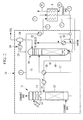
- Fig. 2 is a schematic view for explaining the CO 2 recovery unit in the exhaust gas treatment system according to the first embodiment.
- the CO 2 recovery unit 10 of the first embodiment includes a CO 2 absorption column 11, an absorbing solution regeneration column 16, and a reboiler 21.
- Placed on the upstream side of the CO 2 absorption column 11 is an exhaust gas cooling unit (unshown), which cools the exhaust gas discharged from the combustion facility with cooling water.
- the cooled exhaust gas containing CO 2 is supplied into the CO 2 absorption column 11 through a lower portion of the CO 2 absorption column 11.
- the CO 2 absorption column 11 is composed of a CO 2 recovery section 12 and a water washing section 13 in order from the gas upstream side.
- a CO 2 absorbing solution is sprayed into the exhaust gas.
- the CO 2 absorbing solution has, for example, an amine solution as a base. Consequently, the exhaust gas and the CO 2 absorbing solution come into counter-current contact, and CO 2 in the exhaust gas is absorbed by the CO 2 absorbing solution due to a chemical reaction.
- the exhaust gas with CO 2 removed is conveyed to the water washing section 13. Circulating cleaning water is sprayed into the exhaust gas from the upside of the water washing section 13. Accordingly, the exhaust gas and the circulating cleaning water come into gas-liquid contact, so that moisture contained in the exhaust gas is condensed and the condensed moisture is collected.
- the exhaust gas from which CO 2 and CO 2 absorbing solution removed is discharged to the outside of the system (the smokestack 8 of Fig. 1 ) through an upper portion of the CO 2 absorption column 11.
- the moisture in the exhaust gas condensed in the water washing section 13 and the circulating cleaning water are collected in a tray 14 placed under the water washing section 13. A part of the collected liquid is sprayed in the water washing section 13 as circulating cleaning water. Another part of the collected liquid is discharged from the CO 2 absorption column 11 as process condensate and is supplied to a bottom portion of the absorbing solution regeneration column 16 through a condensate supply pipeline 15.
- the CO 2 absorbing solution (rich solution) which absorbed CO 2 in the CO 2 recovery section 12 is stored in the lower portion of the CO 2 absorption column 11.
- the rich solution is discharged from the CO 2 absorption column 11 by a pump (unshown) and is supplied to an upper portion of the absorbing solution regeneration column 16 through a rich solution supply line 17.
- a regenerating section 18 is provided in the inside of the absorbing solution regeneration column 16. Two or more regenerating sections 18 may be provided.
- the rich solution is sprayed to the inside of the absorbing solution regeneration column 16 from the upper portion of the regenerating section 18. Vapor is fed into the absorbing solution regeneration column 16 from the lower side of the regenerating section 18.
- the rich solution and the vapor come into gas-liquid contact, and a major part of CO 2 is released from the rich solution due to an endothermic reaction.
- the CO 2 absorbing solution (lean solution and condensate) is stored in the bottom portion of the absorbing solution regeneration column 16.
- a part of the CO 2 absorbing solution stored in the bottom portion of the absorbing solution regeneration column 16 is conveyed to an upper portion of the CO 2 recovery section 12 in the CO 2 absorption column 11 through a lean solution supply line 19 by a pump (unshown), and is sprayed into the exhaust gas in the inside of the CO 2 absorption column 11.
- a rich/lean solution heat exchanger 20 is placed in the rich solution supply line 17 and the lean solution supply line 19. In the rich/lean solution heat exchanger 20, heat exchange is performed between the rich solution and the lean solution so that the rich solution is heated while the lean solution is cooled.
- a part of the CO 2 absorbing solution stored in the bottom portion of the absorbing solution regeneration column 16 is supplied to the reboiler 21.
- Vapor from the boiler 2 is supplied to the reboiler 21.
- heat exchange is performed between the CO 2 absorbing solution and the vapor from the boiler 2.
- the CO 2 absorbing solution changes into vapor and is supplied to the absorbing solution regeneration column 16.
- the vapor is cooled into steam condensate and is discharged from the reboiler 21.
- a part of the steam condensate discharged from the reboiler 21 is supplied to a heat exchanger 22.
- the remaining steam condensate is circulated to the boiler.
- heat exchanger 22 heat exchange is performed between the process condensate flowing through the condensate supply pipeline 15 and the steam condensate. As a consequence, the process condensate is heated while the steam condensate is cooled.
- the process condensate and the steam condensate which exchanged heat in the heat exchanger 22 are supplied to the exhaust gas heat exchanger 5.
- heat exchange is performed between the exhaust gas discharged from the boiler 2 and before flowing into the dry electrostatic precipitator 6, the process condensate, and the steam condensate. Accordingly, the exhaust gas is cooled and conveyed to the downstream side of the exhaust gas heat exchanger 5.
- the process condensate is heated and supplied to the bottom portion of the absorbing solution regeneration column 16.
- the steam condensate is heated into a gas-liquid two phase flow through the above heat exchange and is divided into a gas phase and a liquid phase by a gas liquid separation unit 23.
- the gas phase (water vapor) is supplied to a vapor upstream side of the reboiler 21 and is mixed with vapor from the boiler 2, before being supplied to the reboiler 21.
- the liquid phase is supplied to a vapor downstream side of the reboiler 21, and is mixed with the steam condensate discharged from the reboiler 21.
- a part of vapor and steam condensate circulates between the reboiler 21 and the exhaust gas heat exchanger 5.
- the process condensate in the CO 2 absorption column 11 of the CO 2 recovery unit 10 is managed in the temperature range from about 40 to 60°C.
- the process condensate discharged from the CO 2 absorption column at the above temperature range is heated to 70 to 100°C in the heat exchanger 22.
- the steam condensate discharged from the reboiler 21 is cooled to about 75 to 105°C in the heat exchanger 22.
- the exhaust gas discharged from the boiler 2 is cooled to about 130 to 200°C by passing through the air heater 4, and the cooled exhaust gas flows into the exhaust gas heat exchanger 5.
- the exhaust gas is then cooled to 80 to 120°C by the heat exchange performed in the exhaust gas heat exchanger 5.
- the process condensate is further heated to 120 to 160°C, and the steam condensate is heated to 120 to 190°C.
- the temperature rise width of the process condensate and the temperature drop width of the steam condensate by the heat exchanger 22 are controlled with the flow rate of the process condensate and the flow rate of the vapor.
- the temperature rise width of the process condensate and the steam condensate and the temperature drop width of the exhaust gas by the exhaust gas heat exchanger 5 are controlled with the flow rate of the process condensate and the flow rate of the steam condensate.
- the CO 2 desorbed from the CO 2 absorbing solution in the regenerating section of the absorbing solution regeneration column 16 is discharged from a top portion of the absorbing solution regeneration column 16 together with the water vapor released from the rich solution and the semi-lean solution, and is conveyed to a CO 2 separation section 24.
- the CO 2 separation section 24 includes a condenser 25 and a separation drum 26.
- a mixture of water vapor and CO 2 is discharged from the absorbing solution regeneration column 16, and the water vapor is condensed in the condenser 25, and then water is separated in the separation drum 26.
- the CO 2 separated from water is released to the outside of the system.
- the released CO 2 is compressed by a compressor (unshown) and is recovered.
- the water separated from CO 2 by the separation drum 26 is fed to the upper portion of the absorbing solution regeneration column 16 by a pump (unshown).
- the process condensate and the steam condensate are heated through heat exchange within the system, so that the thermal efficiency of the entire apparatus is enhanced.
- the enhanced thermal efficiency of the entire apparatus can decrease the amount of heat required for the reboiler. Since the steam condensate is reheated into vapor and is circulated to the reboiler 21, the amount of vapor fed to the reboiler 21 from the outside (boiler 2) can be decreased.
- the aforementioned temperature of the exhaust gas cooled by the exhaust gas heat exchanger 5 becomes a dew point temperature of sulfur trioxide (SO 3 ) or below. Therefore, as the exhaust gas passes through the exhaust gas heat exchanger 5, the exhaust gas is cooled and SO 3 therein is condensed. A condensed SO 3 mist adheres to dust in the exhaust gas. The dust with SO 3 adhering thereto is collected by the dry electrostatic precipitator 6.
- SO 3 sulfur trioxide
- the exhaust gas contains heavy metals as vapor. As the heavy metals are cooled, they condense into solids. When the exhaust gas is cooled to about 150°C by the air heater 4, most parts of the heavy metals are condensed, but a part thereof is conveyed to the gas downstream side as vapor. As the exhaust gas is further cooled in the exhaust gas heat exchanger 5 placed on the gas downstream side of the air heater 4, almost all the heavy metals are condensed. The condensed heavy metals are mainly collected in the dry electrostatic precipitator 6.
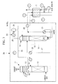
- Fig. 3 is a schematic view for explaining a CO 2 recovery unit in an exhaust gas treatment system according to a second embodiment.
- structure components identical to those in Fig. 2 are designated by identical reference signs.
- the overall structure of the exhaust gas treatment system is identical to that of Fig. 1 .
- a CO 2 recovery unit 30 is different from that in the first embodiment in the point that all the steam condensate discharged from the reboiler 21 exchanges heat in the heat exchanger 22 and the exhaust gas heat exchanger 5 and then is circulated to the boiler 2.
- process condensate in the CO 2 absorption column 11 in the second embodiment is managed in the temperature range from about 40 to 60°C, and the process condensate is heated to 70 to 90°C by the heat exchanger 22.
- the steam condensate discharged from the reboiler 21 is cooled to about 75 to 105°C in the heat exchanger 22.
- the exhaust gas cooled to about 130 to 200°C by the air heater 4 is cooled to 80 to 120°C through heat exchange in the exhaust gas heat exchanger 5.
- the process condensate is further heated to 120 to 160°C, and the steam condensate is heated to 120 to 190°C.
- the amount of heat of the exhaust gas before flowing into the CO 2 recovery unit 10 is used to heat the process condensate and the steam condensate in the CO 2 recovery unit 10, so that the thermal efficiency of the entire apparatus is enhanced.
- Adopting the structure of the second embodiment makes it possible to circulate the steam condensate having the gas phase and the liquid phase mixed therein to the boiler as boiler feed water.
- boiler feed water can be fed to the boiler at temperature higher than conventional temperature, and the efficiency of the boiler can be enhanced thereby.
- the exhaust gas heat exchanger 5 is placed on the gas upstream side of the dry electrostatic precipitator 6, so that the removal efficiency of SO 3 and the removal rate of heavy metals in the exhaust gas treatment system are also enhanced.
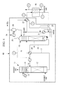
- Fig. 4 is a schematic view for explaining a CO 2 recovery unit in an exhaust gas treatment system according to a third embodiment.
- structure components identical to those in Fig. 2 are designated by identical reference signs.
- the overall structure of the exhaust gas treatment system is identical to that of Fig. 1 .
- a CO 2 recovery unit 40 in the third embodiment is structured so that process condensate discharged from the tray 14 below the water washing section 13 of the CO 2 absorption column 11 exchanges heat with steam condensate in the heat exchanger 22, and then the process condensate is fed to the absorbing solution regeneration column 16 without passing through an exhaust gas heat exchanger 45.
- Other structure is similar to that in the first embodiment.
- the process condensate in the CO 2 absorption column 11 in the second embodiment is managed in the temperature range from about 40 to 60°C, and the process condensate is heated to 70 to 100°C by the heat exchanger 22.
- the steam condensate discharged from the reboiler 21 is cooled to about 75 to 105°C in the heat exchanger 22.
- the exhaust gas cooled to about 130 to 200°C by the air heater 4 is cooled to 80 to 120°C through heat exchange in the exhaust gas heat exchanger 45.
- the steam condensate is heated to 120 to 190°C.
- the exhaust gas treatment system 40 of the third embodiment uses the amount of heat of the exhaust gas to heat the steam condensate, the thermal efficiency of the entire apparatus is enhanced.
- Fig. 5 is a schematic view for explaining a CO 2 recovery unit in an exhaust gas treatment system according to a fourth embodiment.
- structure components identical to those in Fig. 2 are designated by identical reference signs.
- the overall structure of the exhaust gas treatment system is identical to that of Fig. 1 .
- a rich solution supply line branches into a rich solution supply line (first rich solution supply line) 17 and a rich solution supply line (second rich solution supply line) 57 on a rich solution upstream side of the rich/lean solution heat exchanger 20.
- a part of the rich solution discharged from the CO 2 absorption column 11 is supplied to the heat exchanger 22 and to the exhaust gas heat exchanger 5 through the rich solution supply line 57, before being supplied to the absorbing solution regeneration column 16.
- the rich solution stored in the bottom portion of the CO 2 absorption column 11 is managed in the temperature range from about 40 to 60°C.
- the rich solution discharged from the CO 2 absorption column 11 at this temperature range is conveyed to the heat exchanger 22 via the rich solution supply line 57, and is then heated to 70 to 100°C in the heat exchanger 22.
- the steam condensate is cooled to about 75 to 105°C in the heat exchanger 22.
- the rich solution and the steam condensate after heat exchange are supplied to the exhaust gas heat exchanger 5.
- the exhaust gas heat exchanger 5 heat exchange is performed between the rich solution, the steam condensate and the exhaust gas, so that the rich solution and the steam condensate are heated while the exhaust gas is cooled.
- the exhaust gas discharged from the boiler 2 is cooled to about 130 to 200°C by passing through the air heater 4, and the cooled exhaust gas flows into the exhaust gas heat exchanger 5.
- the exhaust gas is then cooled to 80 to 120°C by the heat exchange performed in the exhaust gas heat exchanger 5.
- the rich solution is further heated to 120 to 160°C, and the steam condensate is heated to 120 to 190°C.
- the rich solution heated with the heat of the exhaust gas is fed to the regenerating section 18 of the absorbing solution regeneration column 16 through the rich solution supply line 57.
- the rich solution is preferably fed to the regenerating section 18 of the absorbing solution regeneration column 16 in the height where CO 2 loading of the solution when a part of the rich solution heated with the exhaust gas is flushed into the absorbing solution regeneration column 16 becomes generally equal to CO 2 loading of the solution present in the absorbing solution regeneration column 16.
- CO 2 loading is herein defined as a ratio of CO 2 concentration to absorbing solution (amine) concentration (CO 2 concentration/absorbing solution (amine) concentration).
- the exhaust gas treatment system 50 of the fourth embodiment uses the amount of heat of the exhaust gas to heat the rich solution and the steam condensate, so that the thermal efficiency of the entire apparatus is enhanced. Since the vaporized steam condensate is circulated to the reboiler 21, the amount of vapor fed to the reboiler 21 from the outside (boiler) can be decreased. Moreover, the rich solution is heated and fed to the absorbing solution regeneration column, so that the amount of vapor required for the reboiler 21 can be decreased.
- the exhaust gas heat exchanger 5 is placed on the gas upstream side of the dry electrostatic precipitator 6, so that the removal efficiency of SO 3 and the removal rate of heavy metals in the exhaust gas treatment system are enhanced.
- Fig. 6 is a schematic view for explaining a CO 2 recovery unit in an exhaust gas treatment system according to a fifth embodiment.
- structure components identical to those in Fig. 2 are designated by identical reference signs.
- the overall structure of the exhaust gas treatment system is identical to that of Fig. 1 .
- a rich solution supply line branches into the rich solution supply line (first rich solution supply line) 17 and a rich solution supply line (second rich solution supply line) 67 on a rich solution upstream side of the rich/lean solution heat exchanger 20 as in the fourth embodiment.
- a part of the rich solution discharged from the CO 2 absorption column 11 is supplied to the heat exchanger 22 through the rich solution supply line 67, and then is supplied to the absorbing solution regeneration column 16 without passing through an exhaust gas heat exchanger 65.
- the rich solution which passed through the heat exchanger 22 flows into the absorbing solution regeneration column 16 in generally the same height as the rich solution which passed through the heat exchanger 20. It should be noted that recovered heat of the rich solution which passed through the heat exchanger 22 can be utilized most effectively when the rich solution is fed to the absorbing solution regeneration column 16 in the height where CO 2 loading of the rich solution when a part of the heated rich solution is flushed into the absorbing solution regeneration column 16 becomes generally equal to CO 2 loading of the rich solution present in the absorbing solution regeneration column 16. Accordingly, the feed position of the rich solution is not limited to the one described in the forgoing.
- the rich solution which passed through the heat exchanger 22 may be structured to be fed into the absorbing solution regeneration column 16 from the upper side or the lower side of the supply line of the rich solution which the passed through the heat exchanger 20 depending on the temperature difference between the rich solution which passed through the heat exchanger 22 and the rich solution which passed through the heat exchanger 20.
- the exhaust gas treatment system 60 of the fifth embodiment uses the amount of heat of the exhaust gas to heat the steam condensate and the rich solution, the thermal efficiency of the entire apparatus is enhanced. Moreover, the vaporized steam condensate is circulated to the reboiler 21, so that the amount of vapor fed to the reboiler from the outside (boiler) can be decreased.
- the amount of heat required for the reboiler in the case of treating exhaust gas with use of the exhaust gas treatment system including the CO 2 recovery unit shown in Fig. 2 was calculated.
- the pressure of the process condensate was set at 6 atm, the temperature thereof was set at 49°C at an inlet port of the heat exchanger, 82°C at an outlet port of the heat exchanger, and 149°C at an outlet port of the exhaust gas heat exchanger.
- the temperature of the steam condensate was set at 100°C at the inlet port of the heat exchanger.
- the temperature of the exhaust gas was set at 177°C at an inlet port of the exhaust gas heat exchanger and 90°C at the outlet port of the exhaust gas heat exchanger.
- the flow rate of the process condensate was set at 11.2 ton/hr, and the flow rate of the steam condensate was set at 20.3 ton/hr at the inlet port of the exhaust gas heat exchanger.
- the amount of heat was calculated in consideration of the enthalpy of the steam generated when the steam condensate was evaporated through heat exchange in the exhaust gas heat exchanger.
- the amount of heat required for the reboiler in the case of treating exhaust gas with use of the exhaust gas treatment system including the CO 2 recovery unit shown in Fig. 3 was calculated.
- the temperatures of the process condensate, the steam condensate, and the exhaust gas were set at the same values as in Example 1.
- the flow rate of the process condensate was set at 11.2 ton/hr and the flow rate of the steam condensate was set at 20.3 ton/hr.
- the amount of heat required for the reboiler in the case of treating exhaust gas with use of the exhaust gas treatment system including the CO 2 recovery unit shown in Fig. 4 was calculated.
- the temperature of the process condensate was set at 49°C at the inlet port of the heat exchanger and 96°C at the outlet port of the heat exchanger.
- the temperature of the steam condensate was set at 100°C at the inlet port of the heat exchanger.
- the temperature of the exhaust gas was set at 177°C at the inlet port of the exhaust gas heat exchanger and 90°C at the outlet port of the exhaust gas heat exchanger.
- the flow rate of the process condensate was set at 11.2 ton/hr, and the flow rate of the steam condensate was set at 36.1 ton/hr at the inlet port of the exhaust gas heat exchanger.
- the amount of heat was calculated in consideration of the enthalpy of the steam generated when the steam condensate was evaporated through heat exchange in the exhaust gas heat exchanger.
- the amount of heat required for the reboiler in the case of treating exhaust gas with use of the exhaust gas treatment system including the CO 2 recovery unit shown in Fig. 5 was calculated.
- the pressure of the rich solution was set at 10 atm, and the temperature thereof was set at 39°C at the inlet port of the heat exchanger, 82°C at the outlet port of the heat exchanger, and 149°C at the outlet port of the exhaust gas heat exchanger.
- the temperature of the steam condensate was set at 100°C at the inlet port of the heat exchanger.
- the temperature of the exhaust gas was set at 177°C at the inlet port of the exhaust gas heat exchanger and 90°C at the outlet port of the exhaust gas heat exchanger.
- the flow rate of the rich solution was set at 12.0 ton/hr, and the flow rate of the steam condensate was set at 18.4 ton/hr at the inlet port of the exhaust gas heat exchanger.
- the amount of heat was calculated in consideration of the enthalpy of the steam generated when the steam condensate was evaporated through heat exchange in the exhaust gas heat exchanger.
- the amount of heat required for the reboiler in the case of treating exhaust gas with use of the exhaust gas treatment system including the CO 2 recovery unit shown in Fig. 6 was calculated.
- the temperatures of the rich solution, the steam condensate, and the exhaust gas were set at the same values as in Example 4.
- the flow rate of the rich solution was set at 20.6 ton/hr, and the flow rate of the steam condensate was set at 31.6 ton/hr at the inlet port of the exhaust gas heat exchanger.
- the amount of heat was calculated in consideration of the enthalpy of the steam generated when the steam condensate was evaporated through heat exchange in the exhaust gas heat exchanger.
- a CO 2 recovery unit 70 of Fig. 7 structure components identical to those in Fig. 2 are designated by identical reference signs.
- a heat exchanger 27 is placed on the gas upstream side of a condenser 25 in the CO 2 separation section 24.
- a boiler feed water pipeline 71 is placed so that cooled boiler feed water circulates to the boiler via the heat exchanger 27 of the CO 2 separation section 24 and an exhaust gas heat exchanger 75.
- the CO 2 recovery unit 70 of Fig. 7 is not structured to perform heat exchange of the process condensate and the rich solution with the steam condensate discharged from the reboiler, before supplying the process condensate and the rich solution to the absorbing solution regeneration column.
- the CO 2 recovery unit 70 is not structured to heat the steam condensate in the exhaust gas heat exchanger and to circulate the heated steam condensate to the reboiler.
- Heat exchange is performed, in the heat exchanger 27, between boiler feed water and CO 2 discharged from the absorbing solution regeneration column 16. Accordingly, the boiler feed water is heated and CO 2 is cooled.
- heat exchange is performed between the boiler feed water and exhaust gas. As a consequence, the boiler feed water is heated while the exhaust gas is cooled.
- the temperature of the boiler feed water was set at 83°C at the outlet port of the heat exchanger and 174°C at the outlet port of the exhaust gas heat exchanger.
- the temperature of the exhaust gas was set at 177°C at the inlet port of the exhaust gas heat exchanger and 90°C at the outlet port of the exhaust gas heat exchanger.
- the flow rate of the boiler feed water was set at 31.6 ton/hr.
- Table 1 shows ratios of heat amounts required for the reboiler in Examples 1 to 5 with reference to the calculation result of the Comparative Example. ⁇ Table 1 ⁇ Example 1 Example 2 Example 3 Example 4 Example 5 Ratio of required heat amount 0.84 0.94 0.88 0.90 0.89
- Example 1 As shown in Table 1, the ratio of heat amount required for the reboiler decreased by feeding vapor from the boiler to the reboiler. That is, it was indicated that the exhaust gas treatment system including the CO 2 recovery unit of Examples has the thermal efficiency higher than that of the system including the CO 2 recovery unit of Comparative Example. Further, in Example 1 and Examples 3 to 5 which were structured so that the steam condensate was heated in the exhaust gas heat exchanger and was circulated to the reboiler, the ratio of required heat amount substantially decreased. This indicates that these Examples were more advantageous in the viewpoint of thermal efficiency.
- Example 2 the steam condensate was heated in the exhaust gas heat exchanger and was fed to the boiler, so that the thermal efficiency of the boiler was also enhanced.
Landscapes
- Chemical & Material Sciences (AREA)
- Engineering & Computer Science (AREA)
- Chemical Kinetics & Catalysis (AREA)
- General Chemical & Material Sciences (AREA)
- Oil, Petroleum & Natural Gas (AREA)
- Analytical Chemistry (AREA)
- Environmental & Geological Engineering (AREA)
- Health & Medical Sciences (AREA)
- Biomedical Technology (AREA)
- Organic Chemistry (AREA)
- Inorganic Chemistry (AREA)
- Treating Waste Gases (AREA)
- Gas Separation By Absorption (AREA)
- Carbon And Carbon Compounds (AREA)
Abstract
Description
- The present invention relates to an exhaust gas treatment system having a carbon dioxide (CO2) recovery unit placed for removing CO2 from exhaust gas.
- In thermal power systems for generating power by combusting fossil fuels such as coal and heavy fuel, a large amount of CO2 is discharged. In recent years, the greenhouse effect by CO2 is pointed out as one of the causes of the global warming. It is necessary, therefore, to take prompt measures to protect the global environment on an international basis. Under these circumstances, there is a trend toward further increase in demand for CO2 discharge control.
- In the thermal power systems, there is installed an exhaust gas treatment system including a CO2 recovery unit placed in a flow passage on the downstream side of a boiler. The CO2 recovery unit includes a CO2 absorption column and a CO2 regeneration column as described in
Patent Literature 1 andPatent Literature 2. In the CO2 absorption column, combustion exhaust gas from the boiler is brought into contact with an amine CO2 absorbing solution to remove CO2 in the combustion exhaust gas. The absorbing solution which absorbed CO2 is conveyed to the regeneration column. In the regeneration column, the absorbing solution which absorbed CO2 is heated, and CO2 is released from the absorbing solution. As a result, the absorbing solution is regenerated. The absorbing solution regenerated in the regeneration column is circulated to the CO2 absorption column and is reused therein. The CO2 recovered from the combustion exhaust gas by the CO2 recovery unit is stored without being released to the air or is used for Enhanced Oil Recovery (EOR) and the like. - Since the CO2 recovery unit is placed as an additional structure of a combustion facility, it is also necessary to minimize its operating cost. In the step of regenerating the absorbing solution in particular, a large amount of thermal energy is consumed. Therefore, the regenerating process needs to be energy-saving as much as possible.
- In the exhaust gas treatment system in
Patent Literature 1, a part of an absorbing solution which was extracted through a bottom portion of the CO2 absorption column and supplied to the CO2 regeneration column is preheated through heat exchange with vapor of a reboiler of the CO2 regeneration column, before heat exchange is performed between the absorbing solution and a regenerated absorbing solution which was extracted through a bottom portion of the regeneration column and supplied to the CO2 absorption column. With such a structure, sensible heat of the absorbing solution in the regeneration column increases, so that the vapor amount fed to a CO2 removal facility is reduced. - In the thermal power system in
Patent Literature 2, the amount of heat recovered by cooling the exhaust gas discharged from the boiler is used to heat an absorbing solution which absorbed CO2 and which is supplied from the CO2 absorption column to the regeneration column. Moreover, condensate water from a condenser which returns water vapor sent from a turbine to water is used to cool washing water for use in collection of the absorbing solution in the CO2 absorption column, while the condensate water is also used to cool CO2 separated in the regeneration column. -
- {PTL 1}
Japanese patent application publication No.2011-240321 A - {PTL 2}
Japanese patent application publication No.2012-37180 A - An object of the present invention is to provide an exhaust gas treatment system including a CO2 recovery unit which considerably reduces a water vapor generation amount and further enhances energy efficiency in the system.
- One aspect of the present invention is an exhaust gas treatment system provided on a downstream side of a boiler which combusts fuel to heat water and generate water vapor, comprising: a CO2 recovery unit including a CO2 absorption column for bringing exhaust gas containing CO2 generated in the boiler into contact with a CO2 absorbing solution so that the CO2 absorbing solution absorbs the CO2 and thereby the CO2 is removed out of the exhaust gas, an absorbing solution regeneration column for desorbing the CO2 from the CO2 absorbing solution which absorbed the CO2 to regenerate the CO2 absorbing solution, and a reboiler for heating the CO2 absorbing solution discharged from the absorbing solution regeneration column with water vapor and feeding the vaporized CO2 absorbing solution to the absorbing solution regeneration column; and an exhaust gas heat exchanger provided on a gas upstream side of the CO2 recovery unit, wherein the water vapor is supplied from the boiler to the reboiler, where heat exchange is performed between the CO2 absorbing solution and the water vapor so that the water vapor is cooled into steam condensate, heat exchange is performed between the CO2 absorbing solution discharged from the CO2 absorption column and the steam condensate discharged from the reboiler in a heat exchanger so that the CO2 absorbing solution is heated while the steam condensate is cooled, the CO2 absorbing solution heated in the heat exchanger is fed to the absorbing solution regeneration column, and heat exchange is performed between the cooled steam condensate and the exhaust gas in the exhaust gas heat exchanger so that the steam condensate is heated while the exhaust gas is cooled.
- In the exhaust gas treatment system, the CO2 absorbing solution is preferably process condensate discharged from a water washing section in the CO2 absorption column. Altanatively, in the exhaust gas treatment system, the CO2 absorbing solution is preferably a solution discharged through a bottom portion of the CO2 absorption column.
- In this way, in the exhaust gas treatment system of the present invention, the process condensate and the CO2 absorbing solution (rich solution) discharged from the bottom portion of the CO2 absorption column are heated with the steam condensate discharged from the reboiler, and are supplied to the absorbing solution regeneration column. The steam condensate cooled through heat exchange with the CO2 absorbing solution is reheated with use of the amount of heat of exhaust gas, so that the thermal efficiency of the entire system can be enhanced.
- In the exhaust gas treatment system, it is preferable that heat exchange is performed between the CO2 absorbing solution and the exhaust gas in the exhaust gas heat exchanger so that the CO2 absorbing solution is heated while the exhaust gas is cooled, and that the heated CO2 absorbing solution is supplied to the absorbing solution regeneration column.
- Thus, the CO2 absorbing solution (process condensate or rich solution) is heated with use of the amount of heat of the exhaust gas, so that the thermal efficiency can be further enhanced.
- In the exhaust gas treatment system, the steam condensate heated in the exhaust gas heat exchanger is preferably supplied to the reboiler.
- Through heating with use of the amount of heat of the exhaust gas, water vapor is generated from steam condensate. If this water vapor is supplied to the reboiler, the amount of water vapor, which should be supplied from an outside facility such as a boiler, can be decreased.
- In the exhaust gas treatment system, the steam condensate heated in the exhaust gas heat exchanger is preferably supplied to the boiler.
- With the above structure, boiler feed water can be fed to the boiler at temperature higher than conventional temperature, and the efficiency of the boiler can be enhanced thereby.
- According to the present invention, the heat recovered from exhaust gas is used for CO2 removal process and in the boiler. This makes it possible to enhance the thermal efficiency in the power generation system including the exhaust gas treatment system. At the same time, the removal efficiency of impurities in the exhaust gas can also be enhanced.
-
- {
Fig. 1 }
Fig. 1 is a schematic view of an exhaust gas treatment system. - {
Fig. 2 }
Fig. 2 is a schematic view for explaining a CO2 recovery unit in an exhaust gas treatment system according to a first embodiment. - {
Fig. 3 }
Fig. 3 is a schematic view for explaining a CO2 recovery unit in an exhaust gas treatment system according to a second embodiment. - {
Fig. 4 }
Fig. 4 is a schematic view for explaining a CO2 recovery unit in an exhaust gas treatment system according to a third embodiment. - {
Fig. 5 }
Fig. 5 is a schematic view for explaining a CO2 recovery unit in an exhaust gas treatment system according to a fourth embodiment. - {
Fig. 6 }
Fig. 6 is a schematic view for explaining a CO2 recovery unit in an exhaust gas treatment system according to a fifth embodiment. - {
Fig. 7 }
Fig. 7 is a schematic view for explaining a CO2 recovery unit in an exhaust gas treatment system of Comparative Example 1. -
Fig. 1 is a schematic view of an exhaust gas treatment system according to a first embodiment. An exhaustgas treatment system 1 is placed on a downstream side of a combustion facility such as aboiler 2. Arrows in the drawing indicate the flow of an exhaust gas generated in theboiler 2. The exhaustgas treatment system 1 includes, in order from the gas upstream side, aNOx removal unit 3, anair heater 4, a dryelectrostatic precipitator 6, awet desulfurization unit 7, a *CO2 recovery unit 10, and asmokestack 8. In the exhaustgas treatment system 1 of the first embodiment, an exhaustgas heat exchanger 5 is placed between theair heater 4 and the dryelectrostatic precipitator 6. The exhaustgas heat exchanger 5 may be placed between the dryelectrostatic precipitator 6 and thewet desulfurization unit 7. -
Fig. 2 is a schematic view for explaining the CO2 recovery unit in the exhaust gas treatment system according to the first embodiment. The CO2 recovery unit 10 of the first embodiment includes a CO2 absorption column 11, an absorbingsolution regeneration column 16, and areboiler 21. Placed on the upstream side of the CO2 absorption column 11 is an exhaust gas cooling unit (unshown), which cools the exhaust gas discharged from the combustion facility with cooling water. - The cooled exhaust gas containing CO2 is supplied into the CO2 absorption column 11 through a lower portion of the CO2 absorption column 11. The CO2 absorption column 11 is composed of a CO2 recovery section 12 and a
water washing section 13 in order from the gas upstream side. - In the CO2 recovery section 12, a CO2 absorbing solution is sprayed into the exhaust gas. The CO2 absorbing solution has, for example, an amine solution as a base. Consequently, the exhaust gas and the CO2 absorbing solution come into counter-current contact, and CO2 in the exhaust gas is absorbed by the CO2 absorbing solution due to a chemical reaction.
- The exhaust gas with CO2 removed is conveyed to the
water washing section 13. Circulating cleaning water is sprayed into the exhaust gas from the upside of thewater washing section 13. Accordingly, the exhaust gas and the circulating cleaning water come into gas-liquid contact, so that moisture contained in the exhaust gas is condensed and the condensed moisture is collected. The exhaust gas from which CO2 and CO2 absorbing solution removed is discharged to the outside of the system (thesmokestack 8 ofFig. 1 ) through an upper portion of the CO2 absorption column 11. - The moisture in the exhaust gas condensed in the
water washing section 13 and the circulating cleaning water are collected in atray 14 placed under thewater washing section 13. A part of the collected liquid is sprayed in thewater washing section 13 as circulating cleaning water. Another part of the collected liquid is discharged from the CO2 absorption column 11 as process condensate and is supplied to a bottom portion of the absorbingsolution regeneration column 16 through acondensate supply pipeline 15. - The CO2 absorbing solution (rich solution) which absorbed CO2 in the CO2 recovery section 12 is stored in the lower portion of the CO2 absorption column 11. The rich solution is discharged from the CO2 absorption column 11 by a pump (unshown) and is supplied to an upper portion of the absorbing
solution regeneration column 16 through a richsolution supply line 17. - A regenerating
section 18 is provided in the inside of the absorbingsolution regeneration column 16. Two or moreregenerating sections 18 may be provided. The rich solution is sprayed to the inside of the absorbingsolution regeneration column 16 from the upper portion of the regeneratingsection 18. Vapor is fed into the absorbingsolution regeneration column 16 from the lower side of the regeneratingsection 18. In the regeneratingsection 18, the rich solution and the vapor come into gas-liquid contact, and a major part of CO2 is released from the rich solution due to an endothermic reaction. By the time the CO2 absorbing solution (semi-lean solution) with a part or a major part of CO2 released therefrom reaches the bottom portion of the absorbingsolution regeneration column 16, it is regenerated as a CO2 absorbing solution (lean solution) with almost all CO2 removed therefrom. - The CO2 absorbing solution (lean solution and condensate) is stored in the bottom portion of the absorbing
solution regeneration column 16. A part of the CO2 absorbing solution stored in the bottom portion of the absorbingsolution regeneration column 16 is conveyed to an upper portion of the CO2 recovery section 12 in the CO2 absorption column 11 through a leansolution supply line 19 by a pump (unshown), and is sprayed into the exhaust gas in the inside of the CO2 absorption column 11. A rich/leansolution heat exchanger 20 is placed in the richsolution supply line 17 and the leansolution supply line 19. In the rich/leansolution heat exchanger 20, heat exchange is performed between the rich solution and the lean solution so that the rich solution is heated while the lean solution is cooled. - A part of the CO2 absorbing solution stored in the bottom portion of the absorbing
solution regeneration column 16 is supplied to thereboiler 21. Vapor from theboiler 2 is supplied to thereboiler 21. In a regenerative heater of thereboiler 21, heat exchange is performed between the CO2 absorbing solution and the vapor from theboiler 2. As a consequence, the CO2 absorbing solution changes into vapor and is supplied to the absorbingsolution regeneration column 16. In contrast, the vapor is cooled into steam condensate and is discharged from thereboiler 21. - A part of the steam condensate discharged from the
reboiler 21 is supplied to aheat exchanger 22. The remaining steam condensate is circulated to the boiler. In theheat exchanger 22, heat exchange is performed between the process condensate flowing through thecondensate supply pipeline 15 and the steam condensate. As a consequence, the process condensate is heated while the steam condensate is cooled. - The process condensate and the steam condensate which exchanged heat in the
heat exchanger 22 are supplied to the exhaustgas heat exchanger 5. In the exhaustgas heat exchanger 5, heat exchange is performed between the exhaust gas discharged from theboiler 2 and before flowing into the dryelectrostatic precipitator 6, the process condensate, and the steam condensate. Accordingly, the exhaust gas is cooled and conveyed to the downstream side of the exhaustgas heat exchanger 5. The process condensate is heated and supplied to the bottom portion of the absorbingsolution regeneration column 16. - The steam condensate is heated into a gas-liquid two phase flow through the above heat exchange and is divided into a gas phase and a liquid phase by a gas
liquid separation unit 23. The gas phase (water vapor) is supplied to a vapor upstream side of thereboiler 21 and is mixed with vapor from theboiler 2, before being supplied to thereboiler 21. The liquid phase is supplied to a vapor downstream side of thereboiler 21, and is mixed with the steam condensate discharged from thereboiler 21. Thus, in the exhaust gas treatment system of the first embodiment, a part of vapor and steam condensate circulates between thereboiler 21 and the exhaustgas heat exchanger 5. - In the exhaust gas treatment system of the first embodiment, the process condensate in the CO2 absorption column 11 of the CO2 recovery unit 10 is managed in the temperature range from about 40 to 60°C. The process condensate discharged from the CO2 absorption column at the above temperature range is heated to 70 to 100°C in the
heat exchanger 22. The steam condensate discharged from thereboiler 21 is cooled to about 75 to 105°C in theheat exchanger 22. - In the exhaust gas treatment system of the first embodiment, the exhaust gas discharged from the
boiler 2 is cooled to about 130 to 200°C by passing through theair heater 4, and the cooled exhaust gas flows into the exhaustgas heat exchanger 5. The exhaust gas is then cooled to 80 to 120°C by the heat exchange performed in the exhaustgas heat exchanger 5. In contrast, the process condensate is further heated to 120 to 160°C, and the steam condensate is heated to 120 to 190°C. - The temperature rise width of the process condensate and the temperature drop width of the steam condensate by the
heat exchanger 22 are controlled with the flow rate of the process condensate and the flow rate of the vapor. The temperature rise width of the process condensate and the steam condensate and the temperature drop width of the exhaust gas by the exhaustgas heat exchanger 5 are controlled with the flow rate of the process condensate and the flow rate of the steam condensate. - The CO2 desorbed from the CO2 absorbing solution in the regenerating section of the absorbing
solution regeneration column 16 is discharged from a top portion of the absorbingsolution regeneration column 16 together with the water vapor released from the rich solution and the semi-lean solution, and is conveyed to a CO2 separation section 24. - The CO2 separation section 24 includes a
condenser 25 and aseparation drum 26. A mixture of water vapor and CO2 is discharged from the absorbingsolution regeneration column 16, and the water vapor is condensed in thecondenser 25, and then water is separated in theseparation drum 26. The CO2 separated from water is released to the outside of the system. The released CO2 is compressed by a compressor (unshown) and is recovered. - The water separated from CO2 by the
separation drum 26 is fed to the upper portion of the absorbingsolution regeneration column 16 by a pump (unshown). - In the exhaust
gas treatment system 1 of the present embodiment, the process condensate and the steam condensate are heated through heat exchange within the system, so that the thermal efficiency of the entire apparatus is enhanced. The enhanced thermal efficiency of the entire apparatus can decrease the amount of heat required for the reboiler. Since the steam condensate is reheated into vapor and is circulated to thereboiler 21, the amount of vapor fed to thereboiler 21 from the outside (boiler 2) can be decreased. - When the exhaust
gas heat exchanger 5 is placed on the gas upstream side of the dryelectrostatic precipitator 6, the aforementioned temperature of the exhaust gas cooled by the exhaustgas heat exchanger 5 becomes a dew point temperature of sulfur trioxide (SO3) or below. Therefore, as the exhaust gas passes through the exhaustgas heat exchanger 5, the exhaust gas is cooled and SO3 therein is condensed. A condensed SO3 mist adheres to dust in the exhaust gas. The dust with SO3 adhering thereto is collected by the dryelectrostatic precipitator 6. - The exhaust gas contains heavy metals as vapor. As the heavy metals are cooled, they condense into solids. When the exhaust gas is cooled to about 150°C by the
air heater 4, most parts of the heavy metals are condensed, but a part thereof is conveyed to the gas downstream side as vapor. As the exhaust gas is further cooled in the exhaustgas heat exchanger 5 placed on the gas downstream side of theair heater 4, almost all the heavy metals are condensed. The condensed heavy metals are mainly collected in the dryelectrostatic precipitator 6. - When the exhaust gas heat exchanger is placed before the dry
electrostatic precipitator 6 as in the above case, the removal rate of SO3 and heavy metals are enhanced. -
Fig. 3 is a schematic view for explaining a CO2 recovery unit in an exhaust gas treatment system according to a second embodiment. InFig. 3 , structure components identical to those inFig. 2 are designated by identical reference signs. The overall structure of the exhaust gas treatment system is identical to that ofFig. 1 . - A CO2 recovery unit 30 is different from that in the first embodiment in the point that all the steam condensate discharged from the
reboiler 21 exchanges heat in theheat exchanger 22 and the exhaustgas heat exchanger 5 and then is circulated to theboiler 2. - As in the first embodiment, process condensate in the CO2 absorption column 11 in the second embodiment is managed in the temperature range from about 40 to 60°C, and the process condensate is heated to 70 to 90°C by the
heat exchanger 22. The steam condensate discharged from thereboiler 21 is cooled to about 75 to 105°C in theheat exchanger 22. - The exhaust gas cooled to about 130 to 200°C by the
air heater 4 is cooled to 80 to 120°C through heat exchange in the exhaustgas heat exchanger 5. In contrast, the process condensate is further heated to 120 to 160°C, and the steam condensate is heated to 120 to 190°C. - Thus, in the exhaust
gas treatment system 1 of the present embodiment, the amount of heat of the exhaust gas before flowing into the CO2 recovery unit 10 is used to heat the process condensate and the steam condensate in the CO2 recovery unit 10, so that the thermal efficiency of the entire apparatus is enhanced. - Adopting the structure of the second embodiment makes it possible to circulate the steam condensate having the gas phase and the liquid phase mixed therein to the boiler as boiler feed water. According to the present embodiment, boiler feed water can be fed to the boiler at temperature higher than conventional temperature, and the efficiency of the boiler can be enhanced thereby.
- Also in the exhaust gas treatment system of the present embodiment, the exhaust
gas heat exchanger 5 is placed on the gas upstream side of the dryelectrostatic precipitator 6, so that the removal efficiency of SO3 and the removal rate of heavy metals in the exhaust gas treatment system are also enhanced. -
Fig. 4 is a schematic view for explaining a CO2 recovery unit in an exhaust gas treatment system according to a third embodiment. InFig. 4 , structure components identical to those inFig. 2 are designated by identical reference signs. The overall structure of the exhaust gas treatment system is identical to that ofFig. 1 . - A CO2 recovery unit 40 in the third embodiment is structured so that process condensate discharged from the
tray 14 below thewater washing section 13 of the CO2 absorption column 11 exchanges heat with steam condensate in theheat exchanger 22, and then the process condensate is fed to the absorbingsolution regeneration column 16 without passing through an exhaustgas heat exchanger 45. Other structure is similar to that in the first embodiment. - The process condensate in the CO2 absorption column 11 in the second embodiment is managed in the temperature range from about 40 to 60°C, and the process condensate is heated to 70 to 100°C by the
heat exchanger 22. The steam condensate discharged from thereboiler 21 is cooled to about 75 to 105°C in theheat exchanger 22. - The exhaust gas cooled to about 130 to 200°C by the
air heater 4 is cooled to 80 to 120°C through heat exchange in the exhaustgas heat exchanger 45. In contrast, the steam condensate is heated to 120 to 190°C. - Since the exhaust
gas treatment system 40 of the third embodiment uses the amount of heat of the exhaust gas to heat the steam condensate, the thermal efficiency of the entire apparatus is enhanced. -
Fig. 5 is a schematic view for explaining a CO2 recovery unit in an exhaust gas treatment system according to a fourth embodiment. InFig. 5 , structure components identical to those inFig. 2 are designated by identical reference signs. The overall structure of the exhaust gas treatment system is identical to that ofFig. 1 . - In a CO2 recovery unit 50 of the fourth embodiment, a rich solution supply line branches into a rich solution supply line (first rich solution supply line) 17 and a rich solution supply line (second rich solution supply line) 57 on a rich solution upstream side of the rich/lean
solution heat exchanger 20. A part of the rich solution discharged from the CO2 absorption column 11 is supplied to theheat exchanger 22 and to the exhaustgas heat exchanger 5 through the richsolution supply line 57, before being supplied to the absorbingsolution regeneration column 16. - In the
heat exchanger 22, heat exchange is performed between the rich solution and the steam condensate. In the CO2 recovery unit of the fourth embodiment, the rich solution stored in the bottom portion of the CO2 absorption column 11 is managed in the temperature range from about 40 to 60°C. The rich solution discharged from the CO2 absorption column 11 at this temperature range is conveyed to theheat exchanger 22 via the richsolution supply line 57, and is then heated to 70 to 100°C in theheat exchanger 22. In contrast, the steam condensate is cooled to about 75 to 105°C in theheat exchanger 22. - The rich solution and the steam condensate after heat exchange are supplied to the exhaust
gas heat exchanger 5. In the exhaustgas heat exchanger 5, heat exchange is performed between the rich solution, the steam condensate and the exhaust gas, so that the rich solution and the steam condensate are heated while the exhaust gas is cooled. In the exhaust gas treatment system of the fourth embodiment, the exhaust gas discharged from theboiler 2 is cooled to about 130 to 200°C by passing through theair heater 4, and the cooled exhaust gas flows into the exhaustgas heat exchanger 5. The exhaust gas is then cooled to 80 to 120°C by the heat exchange performed in the exhaustgas heat exchanger 5. In contrast, the rich solution is further heated to 120 to 160°C, and the steam condensate is heated to 120 to 190°C. - The rich solution heated with the heat of the exhaust gas is fed to the regenerating
section 18 of the absorbingsolution regeneration column 16 through the richsolution supply line 57. The rich solution is preferably fed to the regeneratingsection 18 of the absorbingsolution regeneration column 16 in the height where CO2 loading of the solution when a part of the rich solution heated with the exhaust gas is flushed into the absorbingsolution regeneration column 16 becomes generally equal to CO2 loading of the solution present in the absorbingsolution regeneration column 16. - The term "CO2 loading" is herein defined as a ratio of CO2 concentration to absorbing solution (amine) concentration (CO2 concentration/absorbing solution (amine) concentration).
- The exhaust
gas treatment system 50 of the fourth embodiment uses the amount of heat of the exhaust gas to heat the rich solution and the steam condensate, so that the thermal efficiency of the entire apparatus is enhanced. Since the vaporized steam condensate is circulated to thereboiler 21, the amount of vapor fed to thereboiler 21 from the outside (boiler) can be decreased. Moreover, the rich solution is heated and fed to the absorbing solution regeneration column, so that the amount of vapor required for thereboiler 21 can be decreased. - Also in the exhaust gas treatment system of the present embodiment, the exhaust
gas heat exchanger 5 is placed on the gas upstream side of the dryelectrostatic precipitator 6, so that the removal efficiency of SO3 and the removal rate of heavy metals in the exhaust gas treatment system are enhanced. -
Fig. 6 is a schematic view for explaining a CO2 recovery unit in an exhaust gas treatment system according to a fifth embodiment. InFig. 6 , structure components identical to those inFig. 2 are designated by identical reference signs. The overall structure of the exhaust gas treatment system is identical to that ofFig. 1 . - In a CO2 recovery unit 60 in the fifth embodiment, a rich solution supply line branches into the rich solution supply line (first rich solution supply line) 17 and a rich solution supply line (second rich solution supply line) 67 on a rich solution upstream side of the rich/lean
solution heat exchanger 20 as in the fourth embodiment. A part of the rich solution discharged from the CO2 absorption column 11 is supplied to theheat exchanger 22 through the richsolution supply line 67, and then is supplied to the absorbingsolution regeneration column 16 without passing through an exhaustgas heat exchanger 65. - In the
heat exchanger 22, the heat exchange similar to that in the fourth embodiment is performed. - As shown in
Fig. 6 , the rich solution which passed through theheat exchanger 22 flows into the absorbingsolution regeneration column 16 in generally the same height as the rich solution which passed through theheat exchanger 20. It should be noted that recovered heat of the rich solution which passed through theheat exchanger 22 can be utilized most effectively when the rich solution is fed to the absorbingsolution regeneration column 16 in the height where CO2 loading of the rich solution when a part of the heated rich solution is flushed into the absorbingsolution regeneration column 16 becomes generally equal to CO2 loading of the rich solution present in the absorbingsolution regeneration column 16. Accordingly, the feed position of the rich solution is not limited to the one described in the forgoing. For example, the rich solution which passed through theheat exchanger 22 may be structured to be fed into the absorbingsolution regeneration column 16 from the upper side or the lower side of the supply line of the rich solution which the passed through theheat exchanger 20 depending on the temperature difference between the rich solution which passed through theheat exchanger 22 and the rich solution which passed through theheat exchanger 20. - Since the exhaust
gas treatment system 60 of the fifth embodiment uses the amount of heat of the exhaust gas to heat the steam condensate and the rich solution, the thermal efficiency of the entire apparatus is enhanced. Moreover, the vaporized steam condensate is circulated to thereboiler 21, so that the amount of vapor fed to the reboiler from the outside (boiler) can be decreased. - The amount of heat required for the reboiler in the case of treating exhaust gas with use of the exhaust gas treatment system including the CO2 recovery unit shown in
Fig. 2 was calculated. In the calculation, the pressure of the process condensate was set at 6 atm, the temperature thereof was set at 49°C at an inlet port of the heat exchanger, 82°C at an outlet port of the heat exchanger, and 149°C at an outlet port of the exhaust gas heat exchanger. The temperature of the steam condensate was set at 100°C at the inlet port of the heat exchanger. The temperature of the exhaust gas was set at 177°C at an inlet port of the exhaust gas heat exchanger and 90°C at the outlet port of the exhaust gas heat exchanger. The flow rate of the process condensate was set at 11.2 ton/hr, and the flow rate of the steam condensate was set at 20.3 ton/hr at the inlet port of the exhaust gas heat exchanger. The amount of heat was calculated in consideration of the enthalpy of the steam generated when the steam condensate was evaporated through heat exchange in the exhaust gas heat exchanger. - The amount of heat required for the reboiler in the case of treating exhaust gas with use of the exhaust gas treatment system including the CO2 recovery unit shown in
Fig. 3 was calculated. In the calculation, the temperatures of the process condensate, the steam condensate, and the exhaust gas were set at the same values as in Example 1. The flow rate of the process condensate was set at 11.2 ton/hr and the flow rate of the steam condensate was set at 20.3 ton/hr. - The amount of heat required for the reboiler in the case of treating exhaust gas with use of the exhaust gas treatment system including the CO2 recovery unit shown in
Fig. 4 was calculated. In the calculation, the temperature of the process condensate was set at 49°C at the inlet port of the heat exchanger and 96°C at the outlet port of the heat exchanger. The temperature of the steam condensate was set at 100°C at the inlet port of the heat exchanger. The temperature of the exhaust gas was set at 177°C at the inlet port of the exhaust gas heat exchanger and 90°C at the outlet port of the exhaust gas heat exchanger. The flow rate of the process condensate was set at 11.2 ton/hr, and the flow rate of the steam condensate was set at 36.1 ton/hr at the inlet port of the exhaust gas heat exchanger. The amount of heat was calculated in consideration of the enthalpy of the steam generated when the steam condensate was evaporated through heat exchange in the exhaust gas heat exchanger. - The amount of heat required for the reboiler in the case of treating exhaust gas with use of the exhaust gas treatment system including the CO2 recovery unit shown in
Fig. 5 was calculated. In the calculation, the pressure of the rich solution was set at 10 atm, and the temperature thereof was set at 39°C at the inlet port of the heat exchanger, 82°C at the outlet port of the heat exchanger, and 149°C at the outlet port of the exhaust gas heat exchanger. The temperature of the steam condensate was set at 100°C at the inlet port of the heat exchanger. The temperature of the exhaust gas was set at 177°C at the inlet port of the exhaust gas heat exchanger and 90°C at the outlet port of the exhaust gas heat exchanger. The flow rate of the rich solution was set at 12.0 ton/hr, and the flow rate of the steam condensate was set at 18.4 ton/hr at the inlet port of the exhaust gas heat exchanger. The amount of heat was calculated in consideration of the enthalpy of the steam generated when the steam condensate was evaporated through heat exchange in the exhaust gas heat exchanger. - The amount of heat required for the reboiler in the case of treating exhaust gas with use of the exhaust gas treatment system including the CO2 recovery unit shown in
Fig. 6 was calculated. In the calculation, the temperatures of the rich solution, the steam condensate, and the exhaust gas were set at the same values as in Example 4. The flow rate of the rich solution was set at 20.6 ton/hr, and the flow rate of the steam condensate was set at 31.6 ton/hr at the inlet port of the exhaust gas heat exchanger. The amount of heat was calculated in consideration of the enthalpy of the steam generated when the steam condensate was evaporated through heat exchange in the exhaust gas heat exchanger. - The amount of heat required for the reboiler in the case of treating exhaust gas with use of an exhaust gas treatment system including a CO2 recovery unit shown in
Fig. 7 was calculated. - In
Fig. 7 , structure components identical to those inFig. 2 are designated by identical reference signs. In a CO2 recovery unit 70 ofFig. 7 , aheat exchanger 27 is placed on the gas upstream side of acondenser 25 in the CO2 separation section 24. A boilerfeed water pipeline 71 is placed so that cooled boiler feed water circulates to the boiler via theheat exchanger 27 of the CO2 separation section 24 and an exhaustgas heat exchanger 75. However, the CO2 recovery unit 70 ofFig. 7 is not structured to perform heat exchange of the process condensate and the rich solution with the steam condensate discharged from the reboiler, before supplying the process condensate and the rich solution to the absorbing solution regeneration column. Further, the CO2 recovery unit 70 is not structured to heat the steam condensate in the exhaust gas heat exchanger and to circulate the heated steam condensate to the reboiler. - Heat exchange is performed, in the
heat exchanger 27, between boiler feed water and CO2 discharged from the absorbingsolution regeneration column 16. Accordingly, the boiler feed water is heated and CO2 is cooled. Next, in the exhaustgas heat exchanger 75, heat exchange is performed between the boiler feed water and exhaust gas. As a consequence, the boiler feed water is heated while the exhaust gas is cooled. - In the calculation, the temperature of the boiler feed water was set at 83°C at the outlet port of the heat exchanger and 174°C at the outlet port of the exhaust gas heat exchanger. The temperature of the exhaust gas was set at 177°C at the inlet port of the exhaust gas heat exchanger and 90°C at the outlet port of the exhaust gas heat exchanger. The flow rate of the boiler feed water was set at 31.6 ton/hr.
- Table 1 shows ratios of heat amounts required for the reboiler in Examples 1 to 5 with reference to the calculation result of the Comparative Example.
{Table 1} Example 1 Example 2 Example 3 Example 4 Example 5 Ratio of required heat amount 0.84 0.94 0.88 0.90 0.89 - As shown in Table 1, the ratio of heat amount required for the reboiler decreased by feeding vapor from the boiler to the reboiler. That is, it was indicated that the exhaust gas treatment system including the CO2 recovery unit of Examples has the thermal efficiency higher than that of the system including the CO2 recovery unit of Comparative Example. Further, in Example 1 and Examples 3 to 5 which were structured so that the steam condensate was heated in the exhaust gas heat exchanger and was circulated to the reboiler, the ratio of required heat amount substantially decreased. This indicates that these Examples were more advantageous in the viewpoint of thermal efficiency.
- In Example 2, the steam condensate was heated in the exhaust gas heat exchanger and was fed to the boiler, so that the thermal efficiency of the boiler was also enhanced.
-
- 1
- Exhaust gas treatment system
- 2
- Boiler
- 3
- NOx removal unit
- 4
- Air heater
- 5, 45, 65
- Exhaust gas heat exchanger
- 6
- Dry electrostatic precipitator
- 7
- Wet desulfurization unit
- 8
- Smokestack
- 10, 30, 40, 50, 60
- CO2 recovery unit
- 11
- CO2 absorption column
- 12
- CO2 recovery section
- 13
- Water washing section
- 14
- Tray
- 15
- Condensate supply pipeline
- 16
- Absorbing solution regeneration column
- 17, 57, 67
- Rich solution supply line
- 18
- Regenerating section
- 19
- Lean solution supply line
- 20
- Rich/lean solution heat exchanger
- 21
- Reboiler
- 22
- Heat exchanger
- 23
- Gas liquid separation unit
- 24
- CO2 separation section
- 25
- Condenser
- 26
- Separation drum
Claims (6)
- An exhaust gas treatment system provided on a downstream side of a boiler which combusts fuel to heat water and generate water vapor, comprising:a CO2 recovery unit including:a CO2 absorption column for bringing exhaust gas containing CO2 generated in the boiler into contact with a CO2 absorbing solution so that the CO2 absorbing solution absorbs the CO2 and thereby the CO2 is removed out of the exhaust gas;an absorbing solution regeneration column for desorbing the CO2 from the CO2 absorbing solution which absorbed the CO2 to regenerate the CO2 absorbing solution; anda reboiler for heating the CO2 absorbing solution discharged from the absorbing solution regeneration column with water vapor and feeding the vaporized CO2 absorbing solution to the absorbing solution regeneration column; andan exhaust gas heat exchanger provided on a gas upstream side of the CO2 recovery unit, whereinthe water vapor is supplied from the boiler to the reboiler, where heat exchange is performed between the CO2 absorbing solution and the water vapor so that the water vapor is cooled into steam condensed water,heat exchange is performed between the CO2 absorbing solution discharged from the CO2 absorption column and the steam condensed water discharged from the reboiler in a heat exchanger so that the CO2 absorbing solution is heated while the steam condensed water is cooled,the CO2 absorbing solution heated in the heat exchanger is fed to the absorbing solution regeneration column, andheat exchange is performed between the cooled steam condensed water and the exhaust gas in the exhaust gas heat exchanger so that the steam condensed water is heated while the exhaust gas is cooled.
- The exhaust gas treatment system according to claim 1, wherein the CO2 absorbing solution is process condensate discharged from a water washing section in the CO2 absorption column.
- The exhaust gas treatment system according to claim 1, wherein the CO2 absorbing solution is a solution discharged from a bottom portion of the CO2 absorption column.
- The exhaust gas treatment system according to claim 1, wherein heat exchange is performed between the CO2 absorbing solution and the exhaust gas in the exhaust gas heat exchanger so that the CO2 absorbing solution is heated while the exhaust gas is cooled, and the heated CO2 absorbing solution is supplied to the absorbing solution regeneration column.
- The exhaust gas treatment system according to claim 1, wherein the steam condensate heated in the exhaust gas heat exchanger is supplied to the reboiler.
- The exhaust gas treatment system according to claim 1, wherein the steam condensate heated in the exhaust gas heat exchanger is supplied to the boiler.
Applications Claiming Priority (2)
| Application Number | Priority Date | Filing Date | Title |
|---|---|---|---|
| US13/571,001 US20140041523A1 (en) | 2012-08-09 | 2012-08-09 | Exhaust gas treatment system |
| PCT/JP2013/070996 WO2014024791A1 (en) | 2012-08-09 | 2013-08-02 | Exhaust gas treatment system |
Publications (2)
| Publication Number | Publication Date |
|---|---|
| EP2883595A1 true EP2883595A1 (en) | 2015-06-17 |
| EP2883595A4 EP2883595A4 (en) | 2016-03-09 |
Family
ID=50065191
Family Applications (1)
| Application Number | Title | Priority Date | Filing Date |
|---|---|---|---|
| EP13828275.1A Withdrawn EP2883595A4 (en) | 2012-08-09 | 2013-08-02 | Exhaust gas treatment system |
Country Status (6)
| Country | Link |
|---|---|
| US (1) | US20140041523A1 (en) |
| EP (1) | EP2883595A4 (en) |
| JP (1) | JP5976812B2 (en) |
| AU (1) | AU2013300693B2 (en) |
| CA (1) | CA2877852C (en) |
| WO (1) | WO2014024791A1 (en) |
Families Citing this family (12)
| Publication number | Priority date | Publication date | Assignee | Title |
|---|---|---|---|---|
| US10195561B2 (en) * | 2012-09-20 | 2019-02-05 | Mitsubishi Heavy Industries Engineering, Ltd. | Steam supply system and CO2 recovery unit including the same |
| GB201218949D0 (en) * | 2012-10-22 | 2012-12-05 | Bp Alternative Energy Internat Ltd | Separatiion of components from a gas mixture |
| US9314732B2 (en) * | 2013-01-09 | 2016-04-19 | Fluor Technologies Corporation | Systems and methods for reducing the energy requirements of a carbon dioxide capture plant |
| US9616374B2 (en) * | 2013-12-14 | 2017-04-11 | Millenium Synthfuels Corporation | Multi-stage temperature based separation of gas impurities |
| WO2018189947A1 (en) * | 2017-04-13 | 2018-10-18 | 関西電力株式会社 | Carbon dioxide recovery system and carbon dioxide recovery method |
| KR102079796B1 (en) * | 2018-10-04 | 2020-02-20 | 두산중공업 주식회사 | Electric precipitator module desulfurization equipment including the same |
| JP7177734B2 (en) * | 2019-03-20 | 2022-11-24 | 三菱重工エンジニアリング株式会社 | ABSORBENT LIQUID REGENERATION DEVICE, CO2 RECOVERY DEVICE, AND METHOD OF MODIFYING ABSORBENT LIQUID REGENERATION DEVICE |
| JP7152975B2 (en) * | 2019-03-20 | 2022-10-13 | 三菱重工エンジニアリング株式会社 | Absorbing liquid regeneration device, CO2 recovery device, and absorbing liquid regeneration method |
| JP7802581B2 (en) * | 2022-03-16 | 2026-01-20 | 三菱重工業株式会社 | Carbon dioxide capture system |
| CN115138190A (en) * | 2022-07-14 | 2022-10-04 | 南方电网电力科技股份有限公司 | System for absorbing carbon dioxide by deep utilization of flue gas waste heat through chemical absorption method |
| CN116099333B (en) * | 2023-04-13 | 2023-06-23 | 清华四川能源互联网研究院 | Produced gas chemical method carbon capture system |
| EP4574241A1 (en) * | 2023-12-21 | 2025-06-25 | Technip Energies France | Repurposing heated condensate to heat an exhaust gas of a carbon capture system |
Family Cites Families (30)
| Publication number | Priority date | Publication date | Assignee | Title |
|---|---|---|---|---|
| DE1494806C3 (en) * | 1966-10-14 | 1975-07-10 | Metallgesellschaft Ag, 6000 Frankfurt | Process for hydrogen sulfide and carbon dioxide scrubbing of fuel and synthesis gases and regeneration of the loaded detergent |
| US3490872A (en) * | 1967-08-29 | 1970-01-20 | Union Oil Co | Production of hydrogen from carbon monoxide and water in alkaline solutions |
| GB1281571A (en) * | 1968-07-13 | 1972-07-12 | Vetrocoke Cokapuania Spa | Improvements in or relating to the removal of CO2 and/or H2S from gaseous mixtures |
| JP2792777B2 (en) * | 1992-01-17 | 1998-09-03 | 関西電力株式会社 | Method for removing carbon dioxide from flue gas |
| JP3486220B2 (en) * | 1994-03-08 | 2004-01-13 | バブコック日立株式会社 | Combustion exhaust gas purification method and apparatus |
| US5618506A (en) * | 1994-10-06 | 1997-04-08 | The Kansai Electric Power Co., Inc. | Process for removing carbon dioxide from gases |
| JP3233802B2 (en) * | 1994-12-15 | 2001-12-04 | 関西電力株式会社 | Method for removing carbon dioxide and nitrogen oxides from flue gas |
| JP4523691B2 (en) * | 2000-03-10 | 2010-08-11 | 三菱重工業株式会社 | Method and apparatus for controlling absorbent of decarbonation equipment |
| JP4274846B2 (en) * | 2003-04-30 | 2009-06-10 | 三菱重工業株式会社 | Carbon dioxide recovery method and system |
| FR2863910B1 (en) * | 2003-12-23 | 2006-01-27 | Inst Francais Du Petrole | METHOD OF CAPTURING CARBON DIOXIDE CONTAINED IN FUMES |
| JP4690659B2 (en) * | 2004-03-15 | 2011-06-01 | 三菱重工業株式会社 | CO2 recovery device |
| JP4875303B2 (en) * | 2005-02-07 | 2012-02-15 | 三菱重工業株式会社 | Carbon dioxide recovery system, power generation system using the same, and methods thereof |
| JP4745682B2 (en) * | 2005-02-23 | 2011-08-10 | 関西電力株式会社 | CO2 recovery apparatus and method |
| JP4773865B2 (en) * | 2006-04-13 | 2011-09-14 | 三菱重工業株式会社 | CO2 recovery device and CO2 recovery method |
| NO333560B1 (en) * | 2006-11-24 | 2013-07-08 | Aker Clean Carbon As | Method and regenerator for regeneration of liquid CO2 absorbent. |
| AU2009216164B2 (en) * | 2008-02-22 | 2011-10-13 | Mitsubishi Heavy Industries, Ltd. | Apparatus for recovering CO2 and method of recovering CO2 |
| JP5558036B2 (en) * | 2008-09-04 | 2014-07-23 | 株式会社東芝 | Carbon dioxide recovery steam power generation system |
| GB0922411D0 (en) * | 2009-12-22 | 2010-02-03 | Johnson Matthey Plc | Conversion of hydrocarbons to carbon dioxide and electrical power |
| JP5638262B2 (en) * | 2010-02-23 | 2014-12-10 | 三菱重工業株式会社 | CO2 recovery apparatus and CO2 recovery method |
| JP2011240321A (en) * | 2010-04-20 | 2011-12-01 | Babcock Hitachi Kk | Exhaust gas treatment system having carbon dioxide removal device |
| US8562719B2 (en) * | 2010-07-06 | 2013-10-22 | General Electric Company | System for acid gas removal |
| JP5639814B2 (en) * | 2010-08-10 | 2014-12-10 | バブコック日立株式会社 | Thermal power generation system with CO2 removal equipment |
| US8632627B2 (en) * | 2010-08-10 | 2014-01-21 | General Electric Company | Gas dehydration system with desiccant transporter |
| JP5631143B2 (en) * | 2010-10-05 | 2014-11-26 | 株式会社日立製作所 | CO2 separation and recovery device and coal gasification combined cycle plant equipped with CO2 separation and recovery device |
| JP5582960B2 (en) * | 2010-10-22 | 2014-09-03 | 株式会社東芝 | Carbon dioxide separation and recovery system and reboiler heat input measurement method |
| JP5174194B2 (en) * | 2011-01-04 | 2013-04-03 | 三菱重工業株式会社 | CO2 recovery apparatus and method |
| US20120180521A1 (en) * | 2011-01-18 | 2012-07-19 | Erickson Donald C | Flue Gas Scrubbing with Aqueous Ammonia |
| JP2013059726A (en) * | 2011-09-13 | 2013-04-04 | Mitsubishi Heavy Ind Ltd | Co2 recovery device and co2 recovery method |
| JP5738137B2 (en) * | 2011-09-13 | 2015-06-17 | 三菱重工業株式会社 | CO2 recovery apparatus and CO2 recovery method |
| EP2786793B1 (en) * | 2011-12-01 | 2017-10-18 | Kabushiki Kaisha Toshiba, Inc. | Carbon dioxide recovery device, carbon dioxide recovery method, and amine compound recovery method |
-
2012
- 2012-08-09 US US13/571,001 patent/US20140041523A1/en not_active Abandoned
-
2013
- 2013-08-02 WO PCT/JP2013/070996 patent/WO2014024791A1/en not_active Ceased
- 2013-08-02 CA CA2877852A patent/CA2877852C/en active Active
- 2013-08-02 EP EP13828275.1A patent/EP2883595A4/en not_active Withdrawn
- 2013-08-02 JP JP2014529468A patent/JP5976812B2/en active Active
- 2013-08-02 AU AU2013300693A patent/AU2013300693B2/en active Active
Also Published As
| Publication number | Publication date |
|---|---|
| AU2013300693B2 (en) | 2015-11-12 |
| EP2883595A4 (en) | 2016-03-09 |
| US20140041523A1 (en) | 2014-02-13 |
| WO2014024791A1 (en) | 2014-02-13 |
| CA2877852A1 (en) | 2014-02-13 |
| CA2877852C (en) | 2016-06-21 |
| JP5976812B2 (en) | 2016-08-24 |
| JPWO2014024791A1 (en) | 2016-07-25 |
| AU2013300693A1 (en) | 2015-01-22 |
Similar Documents
| Publication | Publication Date | Title |
|---|---|---|
| CA2877852C (en) | Exhaust gas treatment system | |
| EP2722097B1 (en) | Combustion exhaust gas treatment system and combustion exhaust gas treatment method | |
| US9138677B2 (en) | Ammonia stripper for a carbon capture system for reduction of energy consumption | |
| EP2907563B1 (en) | Exhaust gas treatment system and method | |
| JP5738137B2 (en) | CO2 recovery apparatus and CO2 recovery method | |
| WO2013039041A1 (en) | Co2 recovery device and co2 recovery method | |
| JP2013226487A (en) | Co2 recovery device and co2 recovery method | |
| JP6004821B2 (en) | CO2 recovery apparatus and CO2 recovery method | |
| WO2013111097A1 (en) | Ammonia capturing by co2 product liquid in water wash liquid | |
| EP2644250B1 (en) | Exhaust gas treatment system | |
| US20230356143A1 (en) | Ammonia-based carbon dioxide abatement system and method, and direct contact cooler therefore |
Legal Events
| Date | Code | Title | Description |
|---|---|---|---|
| PUAI | Public reference made under article 153(3) epc to a published international application that has entered the european phase |
Free format text: ORIGINAL CODE: 0009012 |
|
| 17P | Request for examination filed |
Effective date: 20141223 |
|
| AK | Designated contracting states |
Kind code of ref document: A1 Designated state(s): AL AT BE BG CH CY CZ DE DK EE ES FI FR GB GR HR HU IE IS IT LI LT LU LV MC MK MT NL NO PL PT RO RS SE SI SK SM TR |
|
| AX | Request for extension of the european patent |
Extension state: BA ME |
|
| DAX | Request for extension of the european patent (deleted) | ||
| RA4 | Supplementary search report drawn up and despatched (corrected) |
Effective date: 20160205 |
|
| RIC1 | Information provided on ipc code assigned before grant |
Ipc: B01D 53/62 20060101AFI20160201BHEP Ipc: C01B 31/20 20060101ALI20160201BHEP Ipc: B01D 53/14 20060101ALI20160201BHEP |
|
| STAA | Information on the status of an ep patent application or granted ep patent |
Free format text: STATUS: THE APPLICATION IS DEEMED TO BE WITHDRAWN |
|
| 18D | Application deemed to be withdrawn |
Effective date: 20160906 |