EP2883045B1 - Méthode et système de séparation simultanée d'analytes par électrophorèse - Google Patents
Méthode et système de séparation simultanée d'analytes par électrophorèse Download PDFInfo
- Publication number
- EP2883045B1 EP2883045B1 EP13829717.1A EP13829717A EP2883045B1 EP 2883045 B1 EP2883045 B1 EP 2883045B1 EP 13829717 A EP13829717 A EP 13829717A EP 2883045 B1 EP2883045 B1 EP 2883045B1
- Authority
- EP
- European Patent Office
- Prior art keywords
- separation
- fluid channel
- sample
- channel
- background electrolyte
- Prior art date
- Legal status (The legal status is an assumption and is not a legal conclusion. Google has not performed a legal analysis and makes no representation as to the accuracy of the status listed.)
- Active
Links
Images





Classifications
-
- G—PHYSICS
- G01—MEASURING; TESTING
- G01N—INVESTIGATING OR ANALYSING MATERIALS BY DETERMINING THEIR CHEMICAL OR PHYSICAL PROPERTIES
- G01N27/00—Investigating or analysing materials by the use of electric, electrochemical, or magnetic means
- G01N27/26—Investigating or analysing materials by the use of electric, electrochemical, or magnetic means by investigating electrochemical variables; by using electrolysis or electrophoresis
-
- G—PHYSICS
- G01—MEASURING; TESTING
- G01N—INVESTIGATING OR ANALYSING MATERIALS BY DETERMINING THEIR CHEMICAL OR PHYSICAL PROPERTIES
- G01N27/00—Investigating or analysing materials by the use of electric, electrochemical, or magnetic means
- G01N27/26—Investigating or analysing materials by the use of electric, electrochemical, or magnetic means by investigating electrochemical variables; by using electrolysis or electrophoresis
- G01N27/416—Systems
- G01N27/447—Systems using electrophoresis
- G01N27/453—Cells therefor
-
- G—PHYSICS
- G01—MEASURING; TESTING
- G01N—INVESTIGATING OR ANALYSING MATERIALS BY DETERMINING THEIR CHEMICAL OR PHYSICAL PROPERTIES
- G01N27/00—Investigating or analysing materials by the use of electric, electrochemical, or magnetic means
- G01N27/26—Investigating or analysing materials by the use of electric, electrochemical, or magnetic means by investigating electrochemical variables; by using electrolysis or electrophoresis
- G01N27/416—Systems
- G01N27/447—Systems using electrophoresis
- G01N27/44704—Details; Accessories
- G01N27/44713—Particularly adapted electric power supply
-
- G—PHYSICS
- G01—MEASURING; TESTING
- G01N—INVESTIGATING OR ANALYSING MATERIALS BY DETERMINING THEIR CHEMICAL OR PHYSICAL PROPERTIES
- G01N27/00—Investigating or analysing materials by the use of electric, electrochemical, or magnetic means
- G01N27/26—Investigating or analysing materials by the use of electric, electrochemical, or magnetic means by investigating electrochemical variables; by using electrolysis or electrophoresis
- G01N27/416—Systems
- G01N27/447—Systems using electrophoresis
- G01N27/44704—Details; Accessories
- G01N27/44743—Introducing samples
-
- G—PHYSICS
- G01—MEASURING; TESTING
- G01N—INVESTIGATING OR ANALYSING MATERIALS BY DETERMINING THEIR CHEMICAL OR PHYSICAL PROPERTIES
- G01N27/00—Investigating or analysing materials by the use of electric, electrochemical, or magnetic means
- G01N27/26—Investigating or analysing materials by the use of electric, electrochemical, or magnetic means by investigating electrochemical variables; by using electrolysis or electrophoresis
- G01N27/416—Systems
- G01N27/447—Systems using electrophoresis
- G01N27/44756—Apparatus specially adapted therefor
- G01N27/44791—Microapparatus
Definitions
- the present invention relates to methods for the separation and detection of analytes in a sample using electrophoresis, such as capillary electrophoresis or microchip electrophoresis, and to systems for performing such operations.
- electrophoresis such as capillary electrophoresis or microchip electrophoresis
- the methods and systems are particularly suited to the simultaneous separation and detection of inorganic anions and cations in a sample.
- Electrophoresis encompassing capillary electrophoresis (CE), micellar electrokinetic chromatography (MEKC) and microchip electrophoresis, is a very powerful technique for the analysis of analytes such as ions in a sample.
- capillary electrophoresis separates and detects charged ions of one polarity (i.e. anions or cations) through the application of a voltage potential to cause the charged ions to move through a separation capillary at different rates according to their electrophoretic mobility in the presence of a background electrolyte.
- Such conventional capillary electrophoresis is thus used to detect either the cations present in the sample, or the anions present in the sample.
- the analytes are neutral (uncharged) species
- these analytes can also be separated.
- DOI-CE dual-opposite end injection
- anionic complexing agent also being the anionic probe.
- Metal ions are converted to their chelated forms with EDTA or 2,6-pyridinedicarboxylate and separated from other anionic components under anionic separation conditions. Whilst this simplifies the system, this is only applicable to metals that can form an anionic complex and is not suitable for alkali and alkaline earths.
- This has particular application to techniques that utilise two or more separation channels for the simultaneous separation of ions (e.g. cations in one channel, and anions in the other).
- a method for the simultaneous separation and detection of analytes in a sample through two or more separation channels using electrophoresis comprising injecting the sample into an electrophoresis system comprising two or more separation channels through a single sample injection port which is in fluid communication with the two separation channels, separating analytes in each of the separation channels, and detecting the analytes separated in each of the separation channels.
- a method for the simultaneous separation and detection of analytes in a sample through two or more separation channels using electrophoresis comprising injecting the sample into an electrophoresis system comprising two or more separation channels and a ground electrode located in an interface zone between the entrances to the two separation channels, wherein the sample is injected through a single sample injection port which is in fluid communication with the two separation channels; separating analytes in each of the separation channels; and detecting the analytes separated in each of the separation channels.
- the analytes are ions, and in some embodiments the ions comprise anions and cations.
- the method comprises separating the cations in a first of the two separation channels and the anions in a second of the two separation channels. The cations are then detected in the first separation channel and the anions in the second separation channel.
- a method for the simultaneous separation and detection of anions and cations in a sample using electrophoresis comprising injecting the sample into an electrophoresis system comprising two separation channels and a ground electrode located in an interface zone between the entrances to the two separation channels, wherein the sample is injected through a single sample injection port which is in fluid communication with the two separation channels; separating the cations in a first of the two separation channels and the anions in a second of the two separation channels; and detecting the cations and anions separated in each of the separation channels.
- a positive potential is applied across the first separation channel, and a negative potential is applied across the second separation channel, with a ground electrode located in an interface zone between the entrances to the two separation channels.
- the present method for simultaneous separation and detection of analytes in particular, relies on the supply or injection of a single sample into the system, and the delivery of a portion of that sample into each of the two separation channels.
- the design established herein allows for such a single sample injection, rather than two sample injections, and does so in an arrangement that is simple and robust. This involves the clever arrangement of electrodes involving the ground electrode being located in the interface zone between the entrances to the two separation channels, and the positioning of a positive electrode for applying a large positive voltage across the first separation channel, and a negative electrode for applying a large negative voltage across the second separation channel.
- a different combination of electrodes can be chosen for analytes other than a combination of cations and anions.
- the sample is hydrodynamically loaded into the two separation channels prior to effecting the separation of cations and anions simultaneously in the respective separation channels. This may be achieved through controlled opening and closing of a valve associated with a fluid channel, the fluid channel having an inlet associated with the sample injection port, an interface zone positioned at the entrance to the separation channels, and an outlet downstream of the interface zone. Other techniques can also be used.
- the method described above for the simultaneous separation and detection of analytes in a sample through two or more separation channels using electrophoresis may comprise the following specific steps:
- the analytes comprise anions and cations
- the first charged electrode is a positively charged electrode
- the second charged electrode is a negatively charged electrode
- the first detector detects anions
- the second detector detects cations.
- the method for the simultaneous separation and detection of anions and cations in a sample using electrophoresis may comprise the following steps:
- the methods described above may be conducted in a capillary electrophoresis system, on a microchip, or otherwise.
- the method further comprises channelling two different background electrolytes through each of the separation channels during the separation of cations in one separation channel and the anions in the second separation channel.
- different background electrolytes may be used for the separation of the cations, as compared to the anions
- a multiple electrolyte system with multiple separation channels could alternatively be used for separating the same types of analytes in multiple separation channels.
- the analytes may be neutrally charged species, or ions of one charge only (i.e. either cations or anions, only).
- the analytes may be a combination of one or more such species (neutral, cations or anions).
- Multiple separation channels for separating ions of the same polarity with different electrolytes in each may be used to improve the detection and analysis of the ions present in the sample. More generally, the ability to separate and analyse any analytes using different conditions (eg. background electrolyte, column type, polarity of EOF, etc) simultaneously from a single injection of sample would be of great advantage.
- different conditions eg. background electrolyte, column type, polarity of EOF, etc
- the present application provides a method for the simultaneous separation and detection of anions and cations in a sample using electrophoresis, the method comprising:
- the present application provides the corresponding systems (or apparatus) for performing electrophoresis.
- an electrophoresis system for the simultaneous separation and detection of analytes in a sample, the system comprising:
- the analytes comprise anions and cations
- the first charged electrode is a positively charged electrode
- the second charged electrode is a negatively charged electrode
- the first detector detects anions
- the second detector detects cations.
- the electrophoresis system for the simultaneous separation and detection of anions and cations in a sample, the system comprises:
- analytes such as anions and cations
- a method for the separation and detection of analytes in a sample using electrophoresis in the presence of two or more different electrolytes concurrently comprising providing an electrophoresis system comprising a single sample injection port in fluid communication with two or more separation channels, priming the separation channels with different background electrolytes, injecting the sample through the single sample injection port and into each of the separation channels, applying a voltage potential across each of the separation channels to effect a separation of the analytes in the respective channels during the flow of a different background electrolyte through each of the separation channels, and detecting the presence of the analytes in the sample.
- the expression "priming the separation channels with different background electrolytes” refers to “priming each separation channel with a background electrolyte of a different composition to the background electrolyte primed into the other separation channel”.
- Different composition refers to a different chemical composition, and may, for example, be a difference in the concentration and/or identity of the chemical components in the background electrolyte. This may also be referred to as a buffer.
- This system provides the capability to concurrently analyse samples using different background electrolytes, which can be very useful when different background electrolytes may be suited for the separation of different analytes, such as ions, present in the sample.
- the method the simultaneous separation and detection of analytes in a sample through two or more separation channels using electrophoresis may comprise:
- the first charged electrode may be a positively charged electrode
- the second charged electrode may be a negatively charged electrode
- the first detector detects anions
- the second detector detects cations.
- an electrophoresis system for the simultaneous separation and detection of analytes in a sample, the system comprising:
- the analytes comprise anions and cations
- the first charged electrode is a positively charged electrode
- the second charged electrode is a negatively charged electrode
- the first detector detects anions
- the second detector detects cations.
- the present application relates to methods and systems for the simultaneous separation and detection of analytes, such as anions and cations, in a sample using electrophoresis.
- analytes such as anions and cations
- one method comprises injecting the sample into an electrophoresis system comprising two separation channels through a single sample injection port in fluid communication with the two separation channels, separating the cations in one separation channel and the anions in a second separation channel, and detecting the cations and anions separated in each of the separation channels.
- the two separation columns may be used to separate ions of the same charge (i.e. positive (cations) or negative (anions)), or to separate neutrally charged species.
- the background electrolyte composition can be varied between the two columns, to allow for simultaneous separations to be carried out on the one sample using these different conditions, to as quickly as possible (and within the same device) obtain a better analysis of the analytes, such as ion components, in the sample.
- separation channel encompasses separation capillaries, and other channel arrangements such as micromachined channels in microchips, through which separation of analytes or ions can be effected. Such channels are typically much narrower in diameter than the main fluid channel through which the sample and background electrolyte is delivered into the separation channels.
- capillary electrophoresis it will be understood that the same arrangement may be applied to other forms of electrophoresis such as microchip electrophoresis and MEKC, and therefore such references are not limiting in this regard.
- Figure 1 illustrates schematically one possible arrangement for the apparatus, device or system of one embodiment of the invention.
- the specific apparatus and stages used in the method may involve the following:
- the injection system comprises a single sample injection port.
- the sample injection port is a port through which the sample is delivered into the apparatus by the operator of the apparatus, and excludes systems in which the operator must deliver the sample at two locations.
- the injection system typically will further comprise at least one background electrolyte injection port.
- at least one background electrolyte injection port we describe one embodiment where a single background electrolyte is utilised. Further below a second embodiment based on multiple background electrolytes will be described.
- the sample injection system may further comprise an injector valve which can be operated to control opening of the fluid channel to either the sample injection port, to enable sample entry into the fluid channel, or to the background electrolyte.
- the injector (or injection) valve 27 includes one setting, marked 2, controlling opening of the fluid channel to the sample injection port, and one setting, marked 6, controlling opening of the fluid channel to the background electrolyte.
- the background electrolyte may be pumped through operation of a pump, or any other fluid flow generator, into the fluid channel when the injector valve is positioned to allow the fluid to flow from the background electrolyte reservoir. Consequently, the system may comprise a fluid flow generator for generating a flow of background electrolyte through the fluid channel.
- the fluid channel comprises an inlet at the injection system end of the fluid channel, and an outlet.
- An interface zone of the fluid channel is positioned between the two ends.
- the fluid channel may be provided by a channel that extends between and includes the two opposite arms of a cross-shaped (X-shaped) connection.
- the cross-shaped connection is marked 29.
- the separation channels in this case project into an interface zone of the fluid channel at the cross-junction.
- the tips of the two separation capillaries (separation channels) may protrude into the interface zone of the fluid channel.
- the tips of the separation capillaries i.e. the entrances or openings to the separation channels) are spaced an equal distance from the centre axis of the fluid channel.
- a ground electrode is provided in the interface zone of the fluid channel.
- the ground electrode may be an elongate, hollow electrode, such as a cylindrical electrode. This is shown in the embodiment of Figure 1 as a dark line 22 extending into one arm of the cross-shaped connection 29.
- the cylindrical ground electrode may extend axially from the outlet end of the fluid channel and into the interface zone of the fluid channel. This grounded electrode design enables the sample to be introduced into the separation channel over a much shorter time period compared to the prior art. The time is about one second, compared to the prior art 20-30 second time period.
- the cylindrical wall of the ground electrode may define a portion of the fluid channel, and the outlet of the fluid channel may be via the centre of the cylindrical ground electrode.
- the internal diameter of the fluid channel may be in the region of about 50 to 1000 ⁇ m (i.e. up to 1mm in diameter), such as between 50 and 800 ⁇ m, 100 and 800 ⁇ m, or between 300 and 800 ⁇ m.
- the internal diameter of the fluid channel used in the Examples was 500 ⁇ m.
- the background electrolyte may be stored in a background electrolyte reservoir, which is in fluid communication with the injection system to enable it to flow through the fluid channel.
- the background electrolyte flow rate may be in the region of about 10 to 1000 ⁇ L.min -1 and typically it will be in the region of about 10 to 200 ⁇ L/min.
- the background electrolyte may be of any suitable composition as known in the art.
- the background electrolyte may comprise one or more buffers, and any other typical electrolyte components.
- the background electrolyte may consist of buffers, and may therefore be referred to as a buffer.
- the background electrolyte may comprise a polymer component, such as a polyelectrolyte, such as polyethyleneimine (PEI).
- PEI polyethyleneimine
- the background electrolyte may comprise a charged surfactant.
- An example of a charged surfactant is sodium dodecyl sulphate.
- the charged surfactant interacts with neutrally charged analytes, and the analytes are separated in the separation channel on the basis of the extent to which they interact with the charged surfactant. This may be used in the case of MEKC.
- the separation channels, or separation capillaries may be of the same constitution, or may be different.
- the separation capillaries may be fused silica capillaries.
- Each separation capillary may be coated or uncoated.
- Each capillary may have an internal diameter of about 10 to 100 ⁇ m, such as 10 to 75 ⁇ m.
- the tips of the separation capillaries are suitably positioned an equal distance from the ground electrode. This ensures that the electromagnetic field applied will be even as between the two separation capillaries.
- the distance between the entrances to the first and second separation channels is preferably at least 50 ⁇ m.
- the entrances may be up to 500 ⁇ m apart.
- the capillary internal diameter influences the minimum separation distance required.
- the separation distance should be a minimum of 1 times, preferably 2 times, or up to 20 times the capillary internal diameter.
- a typical separation distance is about 7.5 times the internal diameter - or between about 5 and 10 times the internal diameter.
- each separation capillary may be about 15 cm or longer, and up to 100 cm, although shorter capillary lengths of between 15 cm and 50 cm are preferred, for shorter separation times. This length refers to the total column length. It is noted that the detection zone will typically be spaced apart from the exit end of the capillary, for example, about 10 cm from the exit or outlet end of the capillary, so the effective length is shorter by a length corresponding to the detection zone location.
- the detector associated with each capillary may be positioned at any suitable location along the capillary length, and in some embodiments, is located around 5-15 cm from the inlet to the capillary.
- Each capillary comprises a detection zone. This is spaced apart from the entrance to the capillary a distance sufficient for the separation to have taken place.
- Each detector may be any suitable form of detector for detecting the presence (and relative amount) of the analytes.
- the detector is used for detecting inorganic ions. Examples include optical detectors, such as photometric detectors, and contactless conductivity detectors, including capacitively-coupled contactless conductivity detectors (C 4 D). Other types of detectors known in the art for detecting analytes in electrophoresis (such as MEKC) can be used.
- the signal produced by the detector is suitably converted by a controller into a visual image to facilitate recording and analysis of the signal.
- the detector zone of the separation channel is suitably positioned a distance between 5 cm and 15 cm from the outlet of the separation channel, such as at a distance of about 10 cm from the outlet of the separation channel.
- the detector is aligned with the detection zone.
- the methods/systems enable the detection of the inorganic ions of interest at concentrations of 10 ppm (parts per million) or even less. Detection can be achieved down to 1 ppb (parts per billion). The detection limits depend in part on the detectors used, but with C 4 D detectors these levels are achievable. The system enables the screening within a 1 minute time-frame.
- the inorganic anions that can be separated by the method/system include chloride, sulfate, thiocyanate, fluoride, phosphate, carbonate, nitrate, perchlorate, azide, chlorate and CH 3 SO 3 - ions.
- inorganic cations that can be separated in the method/system include calcium, potassium, sodium, NH 4 + and magnesium. A sample containing a combination of cations and anions selected from the above can be analysed in the present method/system to enable the simultaneous separation and detection of the cations and anions.
- these may include proteins, DNA, aptmers, organic compounds such as hydrocarbons, small organic molecules, pharmaceuticals, biologically active molecules, and so forth.
- the charged electrode for the first separation channel may be a positively charged electrode.
- the charged electrode associated with the first separation channel (for separating anions in some embodiments) is positioned to apply a voltage potential across the first separation channel (which may be in the form of a capillary), with the ground electrode in the interface zone.
- the charged electrode may be located towards or at the outlet end of the first separation channel (or capillary).
- the electrode is typically a high voltage electrode.
- the charged electrode for the second separation channel may be a negatively charged electrode.
- the charged electrode associated with the second separation channel (for separating cations in some embodiments) is positioned to apply a voltage potential across the second separation channel (which may be in the form of a capillary), with the ground electrode in the interface zone.
- the charged electrode may be located towards or at the outlet end of the second separation channel (or capillary).
- the electrode is typically a high voltage electrode.
- a high voltage is applied across the separation channels or capillaries (longitudinally) during the separation stage during flow of background electrolyte through the fluid channel.
- Typical voltages applied during this step are up to 40 kV, such as about 30 kV or 25 kV (positive or negative).
- the voltage may be modulated over this time period - for example, the voltage may increase at a fixed or variable rate up to the maximum voltage being applied, or the voltage may be increased step-wise.
- a voltage potential is applied by the positive and negative electrodes, it is generally of the same magnitude, but of the opposite potential.
- the sample After loading of the sample into the interface zone of the fluid channel by injecting the sample through the single sample injection port to pass into the interface zone of the fluid channel, the sample is loaded into the separation channels. This may be achieved hydrodynamically (through techniques to be described in further detail below), or electrokinetically, through the application of a voltage potential.
- a small voltage potential is applied across the two separation channels (capillaries) for a short period during the final stage of sample injection (loading), to cause ions present in the sample to pass along the respective capillaries.
- This enables a minimum “injection” of ions into the capillary to provide sufficient sensitivity.
- Suitable voltage and time periods for this step are about 1kV for about 1 second (negative for the negative electrode, and positive for the positive electrode), with variation possible between -0.2kV to 5kV for between 0.2 and 3 seconds (with an increased voltage corresponding to a shorter time, and vice versa).
- the sample is hydrodynamically loaded into the two separation channels prior to effecting the separation of cations and anions simultaneously in the respective separation channels.
- the fluid channel comprises a valve for controlling the opening and closing of the fluid channel outlet.
- the hydrodynamic loading may be achieved through controlled opening and closing of this valve. For example, to load the sample into the two separation channels hydrodynamically, the sample is loaded into the interface zone, the fluid channel outlet valve is closed, and then the sample is injected through the sample injection port with the valve still closed to hydrodynamically force the sample into the two separation channels.
- the step of loading the sample through injecting the sample into the single sample injection port to pass into the interface zone of the fluid channel is followed by the separate introduction of background electrolyte into the interface zone. This enables a "plug" of the sample to be loaded into the separation channels.
- the present application also relates to a method and system for the separation and detection of analytes in a sample using electrophoresis in the presence of two or more different electrolytes concurrently.
- the method comprises providing an electrophoresis system comprising a single sample injection port in fluid communication with two or more separation channels, priming the separation channels with different background electrolytes, injecting the sample through the single sample injection port and into each of the separation channels, applying a voltage potential across each of the separation channels to effect a separation of the analytes in the respective channels during the flow of a different background electrolyte through each of the separation channels, and detecting the presence of the analytes in the sample.
- this system provides the capability to concurrently analyse samples using different background electrolytes, which can be very useful when different background electrolytes may be suited for the separation of different analytes present in the sample.
- the background electrolytes differ in their composition, concentration, pH or otherwise.
- one of the separation channels may be for the separation and detection of cations, and the second may be for the separation and detection of anions.
- the separation channels include a separation channel for separating cations and a separation channel for separating anions. Any additional separation channels may be for the separation of cations or anions.
- the separation channels are for separating analytes of the same charge (i.e. positive or negative or neutral).
- this two-electrolyte invention is generally the same as for arrangement as described above, other than for the provision of two background electrolyte injection ports (and two background electrolyte reservoirs) within the injection system. Whilst that is the case, this embodiment is particularly suited to microchip electrophoresis. Accordingly, in the following, we have described the two electrolyte system invention in further detail in the context of microchip electrophoresis.
- the microchip design for a two-electrolyte system may comprise a microchip containing:
- Fluid outlets are provided at the outlet end of the main fluid channel 35, and at the outlet ends of the separation channels 40,43, for draining liquids away from the microchip.
- This microchip design could also be used for the single electrolyte system embodiments described above, either with all three channels 30, 31, 32, or just two fluid channels, one for the sample and the second for the background electrolyte.
- the three channels that lead to the inlet end of the fluid channel are arranged so that when respective background electrolytes are injected into their ports and through the injection channels towards the main fluid channel, the background electrolytes will flow concurrently in their own streams, and without mixing, through the fluid channel.
- two separate streams of background electrolytes flow in parallel through the fluid channel and through portions of the interface zone. Those portions are the left side and the right side of the interface zone, as shown in Figure 7 .
- the separation channel entrances are located in a portion of the interface zone (one side, as shown in Figure 7 ) through which only one of the background electrolyte compositions pass, just the background electrolyte that passes through that portion of the interface zone will flow (when subjected to the required hydrodynamic force) into the subject separation channel.
- the sections of the interface zone through which the different background electrolytes flow constitute longitudinal sections of the fluid channel.
- the fluid channel outlet preferably comprises a valve for the controlled opening and closing of the fluid channel outlet.
- background electrolytes of two different compositions will be used as the first and second background electrolytes. This results in each separation taking place simultaneously in the presence of different background electrolytes. However, it is possible to use background electrolytes of the same composition in the system.
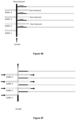
- the step of loading the sample into the two separation channels may take place hydrodynamically or electrophoretically. If hydrodynamic, the fluid channel outlet is closed and the sample is injected through the sample injection port, without the concurrent flow of background electrolyte, and into the separation channels. If electrophoretic, a voltage is applied to electrophoretically inject the sample into the separation channels. Hydrodynamic sample loading (i.e. injection) into the separation channels is represented schematically in Figure 8C .
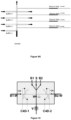
- microchip design for a four-way separation of one embodiment is illustrated in Figure 9 .
- the microchip contains:
- Fluid outlets are also provided at the outlet ends of the separation channels, for draining liquids away from the separation channels on the microchip.
- the arrangement of the background electrolyte channels is such that when respective background electrolytes are injected via the injection ports and into the main fluid channel, the background electrolytes will flow concurrently in their own streams, and without mixing, through the fluid channel.
- the interface zone in this embodiment encompasses the regions of the inlets to the four separation channels, and a different electrolyte flows past each of the separation channel inlets, in separate streams, one after the other through segments of the main fluid channel. This is shown by the shaded flow of streams of background electrolyte in Figure 9B .
- the separation channel entrances are located in a portion of the interface zone (in segments of that zone, as shown in Figure 7 ) through which only one of the background electrolyte compositions pass, just the background electrolyte that passes through that portion of the interface zone will flow (when subjected to the required hydrodynamic force) into the subject separation channel.
- the sample is injected through the sample inlet and through the main channel, as shown in Figure 9C .
- the sample is injected into the separation channels.
- this is conducted electrophoretically through the application of a voltage across the separation channel, although hydrodynamic injection can alternatively be used.
- the four streams of background electrolyte are introduced from the first, second, third and fourth background electrolyte injection ports, through the main fluid channel (with the respective background electrolyte outlets and the main fluid channel outlet open), and into their respective portions of the interface zone of the fluid channel. This takes place without the concurrent flow of sample through the sample injection port.
- microchip used in the above embodiments may be constructed by any suitable technique including, without limitation, micromachining, lithography, casting, embossing or similar, or through a combination of such techniques.
- the channels are generally created in one face of the microchip, and a lid is bonded thereto.
- the fluid channel diameter is typically similar to those used in the microchip system compared to that utilised in capillary electrophoresis, described above.
- the channels in this case may be generally rectangular or hemispherical in cross-section (rather than circular), and have a depth that is smaller than the width.
- the microchip is based on a plastic substrate, channels of rectangular cross-section may be preferred, and when the substrate is glass, hemispherical channels may be preferred.
- the separation channel widths (being the longer dimension for the rectangular channels or the diameter/2 times radius dimension of the semi-circular channels) are typically also about the same as the diameter dimensions noted above for channels of a circular cross-section.
- Typical diameters for such microchip the main fluid channels are around 300 to 500 ⁇ m (and may range from 50 to 500 ⁇ m).
- the depth (corresponding to the radius dimension or maximum depth in the case of semi-circular channels) is typically around 50 ⁇ m (thus, between about 10 and 100 ⁇ m, or between 30 and 70 ⁇ m).
- Typical diameters for the separation channels are 50 ⁇ m (and thus these may range from 10 to 100 ⁇ m).
- the depth of the separation channels may be the same as that for the main fluid channel, or smaller in the case of semi-circular channels.
- the separation channel has a diameter that is typically less than 30% of the diameter of the main fluid channel, for example less than 25%, or less than 20%, compared to the main fluid channel diameter, as this helps to prevent fluids passing through the main fluid channel to pass into the separation channels without hydrodynamic or electrokinetic assistance.
- the electrodes may be of any suitable type and design.
- the electrodes may be contactless electrodes.
- a control system such as a computer, is used to operate the apparatus or device.
- the control system may therefore control the stages of operation of the device, including control of the injection system (such as the valve position), control of the pump operation (and speed of flow of background electrolyte or electrolytes), control of the outlet valve for the fluid channel (if present), application of the voltage potential and so forth.
- the control system may also control the detection system, including processing of the signal received by the detector, and converting that signal into a visual representation (on a display or otherwise).
- the control system may comprise a personal computer or a dedicated control system.
- the controller suitably controls the injection system, flow of background electrolyte and the voltage applied to produce the following sequence of steps:
- the system comprises two or more background electrolyte reservoirs for storing two background electrolytes, and the controller controls the introduction of the two background electrolytes into and through the fluid channel.
- the controller suitably controls the injection system, flow of background electrolyte and the voltage applied to produce the following sequence of steps:
- references to cations and anions can be replaced with references to analytes.
- the controller may present to the user on an associated display a plurality of different desired profiles for which to select.
- the controller uses the selected desired profile to retrieve the relevant operation parameters from a look up table stored in a memory of the controller. That is, in one example, the controller is in data communication with a user interface having a display and one or more input devices.
- the controller has a processor that processes computer readable instructions stored in an associated, tangible memory to present requests for input to a user, receive one or more inputs via the input device(s) and control the radiation source in accordance with the input and the instructions stored in the memory.
- processor is used to refer generically to any device that can process inputs in accordance with stored instructions to control a radiation source and can include: a microprocessor, microcontroller, programmable logic device or other computational device, a general purpose computer (e.g. a PC) or a server.
- the system may be in the form of a device or apparatus.
- the device may be a one-part device, or in separate parts.
- the control system preferably enables at least 10 sample runs per hour, preferably at least 12, or at least 14. 17 sample runs per hour have been achieved to date in the system described in the Examples below.
- a SI-CE system (sequential injection capillary electrophoresis system) was developed in-house.
- a schematic drawing of the bench top system is depicted at Figure 1 (a) .
- a double syringe pump (Harvard Apparatus, Model 33, Holliston, MA, USA) was used to deliver sample and background electrolyte (BGE) to the system.
- BGE background electrolyte
- Two 20 mL plastic syringes Livingstone, Holliston, MA, USA
- glass syringes Hamilton, Reno, NV, USA
- a two position injector valve (MXP-7980, Rheodyne, Oak Harbor, WA, USA) enabled the alternate delivery of sample or BGE to the separation interface.
- a commercial PEEK cross piece connection (P-729, Upchurch Scientific, Oak Harbor, WA, USA) was used to interface the two capillaries to the flow system.
- An isolation valve (HP225K021, NResearch, West Caldwell, NJ, USA) on the crosspiece outlet line allowed for the online flushing of capillaries for equilibration and cleaning.
- An Agilent 35900E A/D convertor (Agilent Technologies, Waldbronn, Germany) was used to interface the C 4 D signals with the Agilent Chemstation software used to record and analyse the signal. Separation on each capillary was driven by either a Spellman CZE2000 or CZE1000 high voltage power supply (Hauppage, NY, USA) working under normal polarity (+) for the cation separation or reversed polarity (-) for the anion separation respectively. Electrodes were immersed in their respective outlet vials.
- the system was controlled via a personal computer using an RS232 serial connection for the syringe pump (RS422 serial connection for milliGAT pump).
- the injection valve, isolation valve and high voltage power supplies were interfaced to the computer via a NI USB-6212 data acquisition device (National Instruments, Austin, Tx, USA). Total system control, less data acquisition, was achieved using in-house written software (Labview 8.1, National Instruments). The system was not thermally controlled and all experiments were performed at ambient room temperature.
- Sample injection was made sequentially and typical separation sequence steps are detailed in Table 1.
- the interface was filled with sample followed by application of a high voltage for 1 s to inject sample anions and cations onto their respective separation capillaries.
- the sample was flushed from the interface at 500 ⁇ Lmin -1 and reduced to 50 ⁇ Lmin -1 when the separation voltage was applied.
- the time and flow rates were selected to minimise injection time and the consumption of reagents. Migration times of analytes were not affected by the flow rate of BGE during separation between the range of 50 and 500 ⁇ Lmin -1 when utilising 55 / 50 cm x 50 ⁇ m i.d. capillaries under the final separation conditions.
- a hydrodynamic flush sequence was incorporated to physically clean and re-equilibrate the capillary surface between runs. This was achieved by closing the isolation valve and flowing BGE at 500 -1000 ⁇ Lmin -1 for 5 s to build sufficient pressure in the cross piece interface to flush the capillaries. Following the high flow flush of the capillaries, the isolation valve was reopened and a 5 s pause period was observed to allow the system to equilibrate to ambient pressure prior to the next sample injection.
- This flush step provided three benefits. Firstly it enabled the ability to set the analysis time by allowing unwanted analytes to be flushed past the detector to ensure that they did not interfere with subsequent runs. Secondly, it provided a physical clean of the capillaries to remove partial blockages and air bibbles and finally, it re-equilibrated the capillary surface between runs which significantly increased baseline stability from run to run.
- Analytes were selected to allow a broad and general study of common inorganic ions of interest to water monitoring, explosive analysis and common environmental background ions.
- a standard analyte mix of PO 4 3- , F - , SO 4 2- , ClO 3 - , ClO 4 - , Ca 2+ , K + (all 5 ppm), Cl - (9 ppm), Na + (7 ppm), NH 4 + (2 ppm) and Mg 2+ (1 ppm) was prepared.
- Sodium - 1- methylsulfonate monohydrate (MSA) and Li 2 CO 3 were used as internal standards. Apart from filtration, no sample pre-treatment occurred prior to injection.
- the three studied BGEs were 70 mM (tris(hydroxymethyl)aminomethane (Tris)) / 70 mM N -Cyclohexyl-2-aminoethanesulfonic acid (CHES), pH 8.6, 50 mM 2-( N- morpholino)ethanesulfonic acid (MES) / 50mM L -histidine (His), pH 6.1, and a 50 mM acetic acid (AA) / 10 mM His, pH 4.2.
- Hexadimethrine bromide (HDMB) was employed to coat the walls of the fused-silica capillaries in order to reverse the electroosmotic flow when required.
- LPA coated capillary of 50 ⁇ m i.d. was purchased from Polymicro Technologies. They were conditioned by flushing at 0.5 ⁇ Lmin -1 with Milli-Q water for 10 minutes. In all cases, capillary equilibration was achieved by flushing capillaries with BGE for 30 minutes at 5 ⁇ Lmin -1 after assembly of the separation interface.
- LPA Linear Poly Acrylamide
- the first BGE selected for use in the separation of cations and anions in these experiments comprised 10 mM L -histidine (His) and 50 mM acetic acid at pH ⁇ 4 with various concentrations of 18-Crown-6 ether.
- a second buffer selected for use comprised of 20 mM MES/ 20 mM His buffer at pH 6.1. This buffer is popular for the separation of cations and has been used in microchip CE separations of both anions and cations. Here, the concentration was adjusted to 50 mM MES/ 50 mM His in order to increase signal response in this system.
- the third and final BGE selected for use consisted of 70 mM Tris and 70 mM CHES at pH 8.6, which is an effective BGE for the separation of inorganic anions and low molecular weight organic acids.
- the third and final BGE selected for use consisted of 70 mM Tris and 70 mM CHES at pH 8.6, which is an effective BGE for the separation of inorganic anions and low molecular weight organic acids.
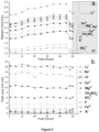
- Figure 4 shows the results of the simultaneous co-EOF separation of the standard anions and cations in the three different BGEs.
- the migration times of all cations increased with buffer pH due to an increase in the magnitude of the EOF. It would be expected that only minor influences on the migration times of the anions would be observed, however, this was not always the case.
- the variation in migration times (especially anions) between replacements of capillaries was most noticeable in the Tris/CHES BGE where cation separation EOF was the greatest (and the anion capillary EOF was considerable).
- the Tris/CHES buffer provided fast migration times, good signal response and the most stable baseline of all three buffers, however satisfactory resolution of NO 3 - and SO 4 2- was not achieved over a maximum run time of three minutes. Further, the HDMB coating would last no more than 80 runs before a 10% increase for the slowest analyte's migration time (HPO 4 2- ) relative to the first run occurred. Eventually, the EOF signal in the anion separation would disappear completely accompanied by a significant increase in migration times for the anions, indicating a significant degradation of the surface coating.
- anion selectivity was unsatisfactory over a maximum separation time of three minutes.
- the acetic acid/Histidine buffer provided for suitable resolution of all anionic species although the migration time of HPO 4 2- was significantly greater than that of the next slowest analyte (SO 4 2- ) and significant tailing of the Fl - ion occurred for HDMB coated capillaries, suggesting a wall interaction with the positively charged HDMB coating.
- the selectivity of SO 4 2- was also altered from the same separation carried out in either BFS or LPA coated capillaries (compare to figure 4 ) presumably due to interaction with the HDMB.
- the capillary lengths were extended to 55cm (35 cm effective length) for the cation separation and 50 cm (28 cm effective length) for the anion separation.
- a microfluidic approach was used for delivering individualised separation chemistries (background electrolyte compositions) to separate microchannels for simultaneous analysis of the analytes in a sample.
- individualised separation chemistries background electrolyte compositions
- hydrodynamic injection of a single sample into two separation channels using dyes and applied to the analysis of inorganic cations.
- the technique used involved (i) laminar flow to introduce flexible and individual separation chemistries with optimal selectivity for simultaneous comprehensive analysis and (ii) hydrodynamic control for non-biased injections in chip CE.
- a low Reynolds number dictates a laminar flow regime.
- Laminar flow enables different liquids to flow alongside one and another without mixing other than by diffusion.
- Channel structures (height 15 ⁇ m) were made by hot embossing in 1.5 mm PMMA using a PDMS master, and were sealed with a 1.5 mm thick PMMA substrate using an office laminator.
- Channels S, B1 and B2 are 450 ⁇ m wide; channels B1-W and B2-W 50 ⁇ m wide.
- PMMA ports with tapped treads were attached to the reservoirs to enable fluidic interfacing using standard Upchurch fittings.
- Sample and the two BGE's, B1 and B2 were pumped into the device using MilliGAT pumps, and flow could be directed into B1-W and B2-W by closing an isolation valve at W. HV electrodes were interfaced with the Upchurch fittings.
- a new method was developed for the integration of electrodes for capacitively coupled contactless conductivity detection (C4D) by filling microchannels with a molten metal alloy. Briefly, the PMMA devices were heated to 80 °C following bonding. Wood's metal, a low metal point alloy, was positioned above a reservoir and drawn into the microchannel using vacuum. The chip was allowed to cool down to room temperature, solidifying the electrode. The detection electrodes were connected to the chip head of a TraceDEC detector and used for C4D. Data acquisition, and control of the pumps, valve and HV supplies was controlled using NI Labview.
- the chip design comprised three inlets for S, B1 and B2, respectively, each connected with a milliGAT pump.
- the valve V When the valve V was open, the flow left the chip at W. Flow into the 50 ⁇ m wide channels B1-W and B2-W was restricted by their high hydrodynamic resistance.
- valve V When valve V was closed, the increased pressure forced liquid into channel B1-W and B2-W, a phenomena used to fill these channels with BGE, and to inject a small plug of sample.
- the molten metal electrodes prepared by the technique described above were used as C4D detection electrodes and metal pins were used for connection with external detection electronics. The continuity of the electrodes was confirmed by connecting it in a circuit with a LED.
- Figure 10 The design depicted in Figure 10 was modified, extending the separation channels to 90 mm.
- the footprint of the substrate (5 x 7.5 cm) remained unchanged, and the separation channels were curved to fit these dimensions.
- the integrated electrodes for C4D were positioned at 70 mm from the injection point. Because the electrode channels are defined lithographically together with the separation channels, no further alignment is required.
- Figure 11(a) shows an electropherogram of the separation of 5 ppm ammonium, sodium and lithium following hydrodynamic injection. To demonstrate the versatility of the flow-control system, it was also applied for electrokinetic detection. Under these conditions, channels B1-W and B2-W were filled with BGE as explained above.
- This example demonstrates the efficacy of a flow-through microchip using laminar flow for simultaneous complementary electrophoretic analysis with individualised separation chemistries.
- the fluidic control enables a new way to hydrodynamically inject a small (60 ⁇ m long) sample plug into two separate separation channels, eliminating electrophoretic bias.
- Molten metal electrodes were used for conductivity detection following hydrodynamic and electrokinetic injection using the new, flow-through device, with electrokinetic injection achieving higher resolution and efficiency.
Landscapes
- Health & Medical Sciences (AREA)
- Life Sciences & Earth Sciences (AREA)
- Chemical & Material Sciences (AREA)
- Molecular Biology (AREA)
- General Physics & Mathematics (AREA)
- Immunology (AREA)
- Physics & Mathematics (AREA)
- Analytical Chemistry (AREA)
- Biochemistry (AREA)
- General Health & Medical Sciences (AREA)
- Chemical Kinetics & Catalysis (AREA)
- Electrochemistry (AREA)
- Pathology (AREA)
- Dispersion Chemistry (AREA)
- Engineering & Computer Science (AREA)
- Power Engineering (AREA)
- Investigating Or Analysing Biological Materials (AREA)
- Other Investigation Or Analysis Of Materials By Electrical Means (AREA)
- Electrostatic Separation (AREA)
- Investigating Or Analyzing Materials By The Use Of Electric Means (AREA)
Claims (14)
- Procédé pour la séparation et la détection simultanées d'analytes dans un échantillon à travers deux ou plusieurs canaux de séparation (16, 19) utilisant l'électrophorèse, le procédé comprenant- injecter l'échantillon dans un système électrophorétique (10) comprenant un canal de fluide ayant une entrée de canal de fluide (13) à une extrémité et une sortie de canal de fluide (14) à l'extrémité opposée, où l'entrée du canal de fluide (13) est en communication de fluide avec un orifice d'injection d'échantillon (12), et où une zone d'interface (15) est positionnée entre l'entrée du canal de fluide (13) et la sortie du canal de fluide (14), le système électrophorétique (10) comprenant en outre deux ou plusieurs canaux de séparation (16, 19) avec des accès positionnés dans la zone d'interface (15) du canal de fluide, où l'échantillon est injecté à travers un seul orifice d'injection d'échantillon qui est en communication de fluide avec les deux canaux de séparation (16, 19) ;caractérisé en ce que- le système électrophorétique (10) comprend une électrode mise à la terre (22) située dans la zone d'interface (15) du canal de fluide ; et- le procédé comprend la séparation des analytes dans chacun des canaux de séparation (16, 19) à travers l'application d'un potentiel de tension à travers chaque canal de séparation (16, 19) pendant le flux d'un électrolyte de fond à travers le canal de fluide de l'entrée du canal de fluide (13) jusqu'à la sortie du canal de fluide (14) ;et la détection des analytes séparés dans chacun des canaux de séparation (16, 19).
- Procédé selon la revendication 1, où les analytes comprennent des anions et des cations, et les étapes de séparation des analytes dans chacun des canaux de séparation (16, 19) et de détection des analytes séparés dans chacun des canaux de séparation (16, 19) impliquent une séparation des cations dans un premier (16) des deux canaux de séparation et des anions dans un deuxième (19) des deux canaux de séparation, et une détection des cations dans le premier canal de séparation (16) et des anions dans le deuxième canal de séparation (19).
- Procédé selon la revendication 2, où un potentiel positif est appliqué à travers le premier (16) des canaux de séparation et un potentiel négatif est appliqué à travers le deuxième (19) des canaux de séparation.
- Procédé selon la revendication 2 ou la revendication 3, où l'électrode de terre (22) s'étend axialement de l'extrémité de sortie (14) du canal de fluide et dans la zone d'interface (15) du canal de fluide.
- Procédé selon la revendication 4, où des accès aux canaux de séparation (16, 19) sont positionnés à égale distance de l'électrode de terre (22).
- Procédé selon l'une quelconque des revendications 2 à 5, où l'échantillon est chargé hydrodynamiquement dans les deux canaux de séparation (16, 19) avant d'effectuer la séparation des cations et des anions simultanément dans les canaux de séparation respectifs.
- Procédé selon la revendication 6, où le chargement hydrodynamique est atteint à travers une ouverture et fermeture contrôlées d'une soupape associée au canal de fluide.
- Procédé selon la revendication 7, où le chargement hydrodynamique d'échantillon comprend les étapes suivantes :- amorcer les canaux de séparation (16, 19) en fermant la soupape de sortie de canal de fluide pour forcer hydrodynamiquement l'électrolyte de fond dans les premier et deuxième canaux de séparation (16, 19) ;- charger un échantillon dans la zone d'interface (15) avec la sortie du canal de fluide (14) ouverte ;- fermer la sortie du canal de fluide (14) et injecter l'échantillon à travers l'orifice d'injection d'échantillon pour forcer hydrodynamiquement l'échantillon dans les deux canaux de séparation (16, 19) pour ainsi charger l'échantillon dans les canaux de séparation (16, 19) ;- introduire une électrolyte de fond à travers le canal de fluide et dans la zone d'interface (15) du canal de fluide avec la sortie du canal de fluide (14) ouverte; et- appliquer un potentiel de tension à travers les canaux de séparation (16,19) pour effectuer une séparation des analytes pendant le flux d'électrolyte de fond à travers le canal de fluide de l'entrée du canal de fluide (13) jusqu'à la sortie du canal de fluide (14).
- Procédé selon l'une quelconque des revendications 2 à 8, où deux électrolytes de fond différents sont canalisés à travers chacun des canaux de séparation (16, 19) pendant la séparation des cations dans le premier canal de séparation (16) et des anions dans le deuxième canal de séparation (19).
- Système électrophorétique (10) pour la séparation et la détection simultanées d'analytes dans un échantillon, le système comprenant :• un système d'injection (11) comprenant un seul orifice d'injection d'échantillon (12) ;• un canal de fluide ayant une entrée de canal de fluide (13) à une extrémité et une sortie de canal de fluide (14) à l'extrémité opposée, où l'entrée du canal de fluide (13) est en communication de fluide avec l'orifice d'injection d'échantillon (12), et où une zone d'interface (15) est positionnée entre l'entrée du canal de fluide (13) et la sortie du canal de fluide (14) ;• un réservoir d'électrolyte de fond pour stocker un électrolyte de fond, en communication de fluide avec le système d'injection (11) pour permettre le flux de l'électrolyte de fond à travers le canal de fluide de l'entrée du canal de fluide (13) et jusqu'à la sortie du canal de fluide (14) ;• un premier canal de séparation (16) ayant un accès positionné dans la zone d'interface (15) du canal de fluide et une première sortie du canal de séparation à l'extrémité opposée ;• un deuxième canal de séparation (19) ayant un accès positionné dans la zone d'interface (15) du canal de fluide et une deuxième sortie du canal de séparation à l'extrémité opposée ;• une électrode mise à la terre (22) positionnée dans la zone d'interface (15) du canal de fluide ;• une première électrode chargée (23) positionnée pour appliquer un potentiel à travers le premier canal de séparation (16) ;• un premier détecteur (24) positionné pour détecter des analytes passant à travers une zone de détection du premier canal de séparation (16) ;• une deuxième électrode chargée (25) positionnée pour appliquer un potentiel à travers le deuxième canal de séparation (19) ;• un deuxième détecteur (26) positionné pour détecter des analytes passant à travers une zone de détection du deuxième canal de séparation (19) ; et• un contrôleur pour commander le système d'injection (11) et le flux d'électrolyte de fond à travers le canal de fluide et l'application d'une tension à travers les électrodes (22,23,25).
- Système selon la revendication 10, où les analytes comprennent des anions et des cations, la première électrode chargée (23) est une électrode chargée positivement, la deuxième électrode chargée (25) est une électrode chargée négativement, le premier détecteur (24) détecte des anions et le deuxième détecteur (26) détecte des cations.
- Système selon l'une quelconque des revendications 10 à 11, où l'électrode mise à la terre (22) est cylindrique.
- Système selon l'une quelconque des revendications 10 à 12, où l'électrode mise à la terre (22) s'étend axialement de l'extrémité de sortie du canal de fluide et dans la zone d'interface (15) du canal de fluide.
- Système selon l'une quelconque des revendications 10 à 13, où :- le réservoir d'électrolyte de fond comprend un premier réservoir d'électrolyte de fond et un deuxième réservoir d'électrolyte de fond, avec des orifices d'injection respectifs positionnés de sorte qu'un électrolyte de fond injecté à travers les orifices d'injection respectifs circulera simultanément à travers des portions du canal de fluide (33) pour traverser des portions de la zone d'interface (35) du canal de fluide (33),- l'accès (39) au premier canal de séparation (38) est positionnée dans la portion de la zone d'interface (35) à travers laquelle le courant d'électrolyte de fond du premier orifice d'injection d'électrolyte de fond passera ; et- l'accès (42) au deuxième canal de séparation (41) est positionné dans la portion de la zone d'interface (35) à travers laquelle le courant d'électrolyte de fond du deuxième orifice d'injection d'électrolyte de fond passera.
Applications Claiming Priority (2)
| Application Number | Priority Date | Filing Date | Title |
|---|---|---|---|
| AU2012903482A AU2012903482A0 (en) | 2012-08-13 | Electrophoretic separation of analytes | |
| PCT/AU2013/000889 WO2014026224A1 (fr) | 2012-08-13 | 2013-08-13 | Séparation d'analytes par électrophorèse |
Publications (4)
| Publication Number | Publication Date |
|---|---|
| EP2883045A1 EP2883045A1 (fr) | 2015-06-17 |
| EP2883045A4 EP2883045A4 (fr) | 2016-03-30 |
| EP2883045B1 true EP2883045B1 (fr) | 2023-10-04 |
| EP2883045C0 EP2883045C0 (fr) | 2023-10-04 |
Family
ID=50101108
Family Applications (1)
| Application Number | Title | Priority Date | Filing Date |
|---|---|---|---|
| EP13829717.1A Active EP2883045B1 (fr) | 2012-08-13 | 2013-08-13 | Méthode et système de séparation simultanée d'analytes par électrophorèse |
Country Status (11)
| Country | Link |
|---|---|
| US (1) | US9683961B2 (fr) |
| EP (1) | EP2883045B1 (fr) |
| JP (1) | JP6341913B2 (fr) |
| KR (1) | KR102151285B1 (fr) |
| CN (2) | CN104541162B (fr) |
| AU (1) | AU2013302301B2 (fr) |
| CA (1) | CA2880591C (fr) |
| IL (1) | IL236978A0 (fr) |
| NZ (1) | NZ704076A (fr) |
| SG (1) | SG11201500523YA (fr) |
| WO (1) | WO2014026224A1 (fr) |
Families Citing this family (13)
| Publication number | Priority date | Publication date | Assignee | Title |
|---|---|---|---|---|
| CN103868970B (zh) * | 2014-03-21 | 2016-01-06 | 上海通微分析技术有限公司 | 全自动高精度毛细管电泳仪 |
| KR101611708B1 (ko) * | 2014-07-07 | 2016-04-11 | 고려대학교 산학협력단 | 연속 등전점 전기영동 디바이스 |
| US9728387B2 (en) * | 2015-10-20 | 2017-08-08 | The University Of North Carolina At Chapel Hill | Solid phase extraction with capillary electrophoresis |
| SG11201900782UA (en) | 2016-08-15 | 2019-02-27 | Univ Tasmania | Inorganic ion detection system and methods |
| US11198118B2 (en) * | 2017-03-29 | 2021-12-14 | Princeton Biochemicals, Inc. | Integrated modular unit containing one or more analyte concentrator-microreactor devices to be coupled to a cartridge-cassette and methods of operation |
| EP3602026B1 (fr) * | 2017-03-30 | 2025-10-08 | 908 Devices Inc. | Analyse microfluidique d'échantillons biologiques |
| CN107728889A (zh) * | 2017-11-02 | 2018-02-23 | 安徽理工大学 | 一种基于LabVIEW的虚拟雷诺实验系统 |
| US11117131B2 (en) | 2018-08-22 | 2021-09-14 | International Business Machines Corporation | Electrokinetically separating, encapsulating and extracting analytes on a microfluidic device |
| CZ2019350A3 (cs) * | 2019-06-05 | 2020-12-16 | Univerzita Karlova | Způsob odběru a přípravy vzorku pro jeho on-line analýzu zejména kapilární elektroforézou a systém k provádění tohoto způsobu |
| US12416603B2 (en) | 2020-05-19 | 2025-09-16 | 10X Genomics, Inc. | Electrophoresis cassettes and instrumentation |
| CN120304039A (zh) | 2022-12-09 | 2025-07-11 | 富士胶片株式会社 | 光电转换元件、摄像元件、光传感器、摄像元件的制造方法、化合物 |
| WO2024203704A1 (fr) | 2023-03-24 | 2024-10-03 | 富士フイルム株式会社 | Élément de conversion photoélectrique, élément d'imagerie, capteur optique et composé |
| CN117531553B (zh) * | 2023-10-16 | 2025-03-18 | 北京大学 | 微纳流控芯片及生化标志物分子的并行富集检测方法 |
Family Cites Families (9)
| Publication number | Priority date | Publication date | Assignee | Title |
|---|---|---|---|---|
| JPS53143397A (en) * | 1977-05-20 | 1978-12-13 | Shimadzu Corp | Constant speed electrophoresis analyzer |
| US6352633B1 (en) * | 1999-08-31 | 2002-03-05 | Spectrumedix Corporation | Automated parallel capillary electrophoresis system with hydrodynamic sample injection |
| US20020112959A1 (en) | 2000-10-04 | 2002-08-22 | Qifeng Xue | Unbiased sample injection for microfluidic applications |
| CN1138862C (zh) * | 2002-01-28 | 2004-02-18 | 国前 | 一种核酸分析用收集装置及其应用方法 |
| US20040163961A1 (en) * | 2003-02-21 | 2004-08-26 | West Virginia University Research Corporation | Apparatus and method for using bi-directional capillary electrophoresis |
| CN2729722Y (zh) * | 2004-09-23 | 2005-09-28 | 复旦大学 | 阴阳离子毛细管电泳电导检测芯片 |
| CN2795855Y (zh) * | 2005-05-19 | 2006-07-12 | 复旦大学 | 三维可调微流控芯片电化学检测装置 |
| US7988839B2 (en) * | 2005-09-20 | 2011-08-02 | University Of Louisville Research Foundation, Inc. | Capillary electrophoresis systems and methods |
| BRPI0622137A2 (pt) * | 2006-11-21 | 2014-07-29 | Medimate Holding B V | Método e aparelho para medição de uma concentração de uma espécie carregada em uma amostra e método para produção de um aparelho |
-
2013
- 2013-08-13 KR KR1020157006292A patent/KR102151285B1/ko active Active
- 2013-08-13 US US14/417,745 patent/US9683961B2/en active Active
- 2013-08-13 CA CA2880591A patent/CA2880591C/fr active Active
- 2013-08-13 AU AU2013302301A patent/AU2013302301B2/en active Active
- 2013-08-13 CN CN201380042717.6A patent/CN104541162B/zh active Active
- 2013-08-13 SG SG11201500523YA patent/SG11201500523YA/en unknown
- 2013-08-13 NZ NZ704076A patent/NZ704076A/en unknown
- 2013-08-13 CN CN201710339402.8A patent/CN107255668A/zh active Pending
- 2013-08-13 EP EP13829717.1A patent/EP2883045B1/fr active Active
- 2013-08-13 JP JP2015526831A patent/JP6341913B2/ja active Active
- 2013-08-13 WO PCT/AU2013/000889 patent/WO2014026224A1/fr not_active Ceased
-
2015
- 2015-01-29 IL IL236978A patent/IL236978A0/en active IP Right Grant
Also Published As
| Publication number | Publication date |
|---|---|
| NZ704076A (en) | 2017-12-22 |
| KR20150042265A (ko) | 2015-04-20 |
| CN104541162A (zh) | 2015-04-22 |
| WO2014026224A1 (fr) | 2014-02-20 |
| SG11201500523YA (en) | 2015-03-30 |
| JP6341913B2 (ja) | 2018-06-13 |
| EP2883045A4 (fr) | 2016-03-30 |
| CN107255668A (zh) | 2017-10-17 |
| US9683961B2 (en) | 2017-06-20 |
| JP2015524927A (ja) | 2015-08-27 |
| KR102151285B1 (ko) | 2020-09-03 |
| EP2883045A1 (fr) | 2015-06-17 |
| HK1209831A1 (en) | 2016-04-08 |
| CN104541162B (zh) | 2017-06-13 |
| CA2880591C (fr) | 2021-03-16 |
| AU2013302301A1 (en) | 2015-02-12 |
| CA2880591A1 (fr) | 2014-02-20 |
| US20150192544A1 (en) | 2015-07-09 |
| EP2883045C0 (fr) | 2023-10-04 |
| IL236978A0 (en) | 2015-03-31 |
| AU2013302301B2 (en) | 2017-06-15 |
Similar Documents
| Publication | Publication Date | Title |
|---|---|---|
| EP2883045B1 (fr) | Méthode et système de séparation simultanée d'analytes par électrophorèse | |
| Gaudry et al. | On-line simultaneous and rapid separation of anions and cations from a single sample using dual-capillary sequential injection-capillary electrophoresis | |
| US5942093A (en) | Electro-osmotically driven liquid delivery method and apparatus | |
| Lichtenberg et al. | Sample preconcentration by field amplification stacking for microchip‐based capillary electrophoresis | |
| EP3365668B1 (fr) | Extraction en phase solide avec électrophorèse capillaire | |
| US8241476B1 (en) | Sol-gel coatings for on-line preconcentration in capillary electrophoresis | |
| Gaudry et al. | Polymeric microchip for the simultaneous determination of anions and cations by hydrodynamic injection using a dual-channel sequential injection microchip electrophoresis system | |
| Mai et al. | Simultaneous separations of cations and anions by capillary electrophoresis with contactless conductivity detection employing a sequential injection analysis manifold for flexible manipulation of sample plugs | |
| Pedersen-Bjergaard et al. | Electrical potential can drive liquid-liquid extraction for sample preparation in chromatography | |
| Kitagawa et al. | Pressurized flow‐driven capillary electrochromatography using ion exchange resins | |
| Chen et al. | Automated Instrumentation for Comprehensive Isotachophoresis− Capillary Zone Electrophoresis | |
| Opekar et al. | Dual-channel capillary electrophoresis for simultaneous determination of cations and anions | |
| Wuersig et al. | Rapid electrophoretic separations in short capillaries using contactless conductivity detection and a sequential injection analysis manifold for hydrodynamic sample loading | |
| Mai et al. | Pressure-assisted capillary electrophoresis for cation separations using a sequential injection analysis manifold and contactless conductivity detection | |
| Sikorsky et al. | Gradient elution moving boundary electrophoresis with field-amplified continuous sample injection | |
| Kaniansky et al. | Column switching in zone electrophoresis on a chip | |
| Vrouwe et al. | Rapid inorganic ion analysis using quantitative microchip capillary electrophoresis | |
| Priego‐Capote et al. | Dual injection capillary electrophoresis: Foundations and applications | |
| Caslavska et al. | Validation of CE modeling with a contactless conductivity array detector | |
| Gáspár et al. | Split injection: A simple introduction of subnanoliter sample volumes for chip electrophoresis | |
| Vogt et al. | A new two-chip concept for continuous measurements on PMMA-microchips | |
| Xia et al. | Application of an electrokinetic backflow for enhancing pressure-driven charge based separations in sub-micrometer deep channels | |
| Chun | Integration of electropreconcentration and electrospray ionization in a microchip | |
| HK1209831B (en) | Electrophoretic separation of analytes | |
| Padarauskas | Dual-opposite injection capillary electrophoresis for the simultaneous separation of anionic and cationic compounds |
Legal Events
| Date | Code | Title | Description |
|---|---|---|---|
| PUAI | Public reference made under article 153(3) epc to a published international application that has entered the european phase |
Free format text: ORIGINAL CODE: 0009012 |
|
| 17P | Request for examination filed |
Effective date: 20150312 |
|
| AK | Designated contracting states |
Kind code of ref document: A1 Designated state(s): AL AT BE BG CH CY CZ DE DK EE ES FI FR GB GR HR HU IE IS IT LI LT LU LV MC MK MT NL NO PL PT RO RS SE SI SK SM TR |
|
| AX | Request for extension of the european patent |
Extension state: BA ME |
|
| DAX | Request for extension of the european patent (deleted) | ||
| RA4 | Supplementary search report drawn up and despatched (corrected) |
Effective date: 20160226 |
|
| RIC1 | Information provided on ipc code assigned before grant |
Ipc: G01N 27/447 20060101AFI20160222BHEP |
|
| STAA | Information on the status of an ep patent application or granted ep patent |
Free format text: STATUS: EXAMINATION IS IN PROGRESS |
|
| 17Q | First examination report despatched |
Effective date: 20210408 |
|
| REG | Reference to a national code |
Ref country code: DE Ref legal event code: R079 Ipc: G01N0027447000 Ref country code: DE Ref legal event code: R079 Ref document number: 602013084753 Country of ref document: DE Free format text: PREVIOUS MAIN CLASS: G01N0027260000 Ipc: G01N0027447000 |
|
| GRAP | Despatch of communication of intention to grant a patent |
Free format text: ORIGINAL CODE: EPIDOSNIGR1 |
|
| STAA | Information on the status of an ep patent application or granted ep patent |
Free format text: STATUS: GRANT OF PATENT IS INTENDED |
|
| RIC1 | Information provided on ipc code assigned before grant |
Ipc: G01N 27/453 20060101ALI20230322BHEP Ipc: G01N 27/447 20060101AFI20230322BHEP |
|
| INTG | Intention to grant announced |
Effective date: 20230417 |
|
| GRAS | Grant fee paid |
Free format text: ORIGINAL CODE: EPIDOSNIGR3 |
|
| GRAA | (expected) grant |
Free format text: ORIGINAL CODE: 0009210 |
|
| STAA | Information on the status of an ep patent application or granted ep patent |
Free format text: STATUS: THE PATENT HAS BEEN GRANTED |
|
| AK | Designated contracting states |
Kind code of ref document: B1 Designated state(s): AL AT BE BG CH CY CZ DE DK EE ES FI FR GB GR HR HU IE IS IT LI LT LU LV MC MK MT NL NO PL PT RO RS SE SI SK SM TR |
|
| RAP3 | Party data changed (applicant data changed or rights of an application transferred) |
Owner name: UNIVERSITY OF TASMANIA |
|
| REG | Reference to a national code |
Ref country code: GB Ref legal event code: FG4D |
|
| REG | Reference to a national code |
Ref country code: CH Ref legal event code: EP |
|
| REG | Reference to a national code |
Ref country code: IE Ref legal event code: FG4D |
|
| REG | Reference to a national code |
Ref country code: DE Ref legal event code: R096 Ref document number: 602013084753 Country of ref document: DE |
|
| U01 | Request for unitary effect filed |
Effective date: 20231031 |
|
| U07 | Unitary effect registered |
Designated state(s): AT BE BG DE DK EE FI FR IT LT LU LV MT NL PT SE SI Effective date: 20231106 |
|
| PG25 | Lapsed in a contracting state [announced via postgrant information from national office to epo] |
Ref country code: GR Free format text: LAPSE BECAUSE OF FAILURE TO SUBMIT A TRANSLATION OF THE DESCRIPTION OR TO PAY THE FEE WITHIN THE PRESCRIBED TIME-LIMIT Effective date: 20240105 |
|
| PG25 | Lapsed in a contracting state [announced via postgrant information from national office to epo] |
Ref country code: IS Free format text: LAPSE BECAUSE OF FAILURE TO SUBMIT A TRANSLATION OF THE DESCRIPTION OR TO PAY THE FEE WITHIN THE PRESCRIBED TIME-LIMIT Effective date: 20240204 |
|
| PG25 | Lapsed in a contracting state [announced via postgrant information from national office to epo] |
Ref country code: ES Free format text: LAPSE BECAUSE OF FAILURE TO SUBMIT A TRANSLATION OF THE DESCRIPTION OR TO PAY THE FEE WITHIN THE PRESCRIBED TIME-LIMIT Effective date: 20231004 |
|
| PG25 | Lapsed in a contracting state [announced via postgrant information from national office to epo] |
Ref country code: IS Free format text: LAPSE BECAUSE OF FAILURE TO SUBMIT A TRANSLATION OF THE DESCRIPTION OR TO PAY THE FEE WITHIN THE PRESCRIBED TIME-LIMIT Effective date: 20240204 Ref country code: GR Free format text: LAPSE BECAUSE OF FAILURE TO SUBMIT A TRANSLATION OF THE DESCRIPTION OR TO PAY THE FEE WITHIN THE PRESCRIBED TIME-LIMIT Effective date: 20240105 Ref country code: ES Free format text: LAPSE BECAUSE OF FAILURE TO SUBMIT A TRANSLATION OF THE DESCRIPTION OR TO PAY THE FEE WITHIN THE PRESCRIBED TIME-LIMIT Effective date: 20231004 |
|
| PG25 | Lapsed in a contracting state [announced via postgrant information from national office to epo] |
Ref country code: RS Free format text: LAPSE BECAUSE OF FAILURE TO SUBMIT A TRANSLATION OF THE DESCRIPTION OR TO PAY THE FEE WITHIN THE PRESCRIBED TIME-LIMIT Effective date: 20231004 Ref country code: PL Free format text: LAPSE BECAUSE OF FAILURE TO SUBMIT A TRANSLATION OF THE DESCRIPTION OR TO PAY THE FEE WITHIN THE PRESCRIBED TIME-LIMIT Effective date: 20231004 Ref country code: NO Free format text: LAPSE BECAUSE OF FAILURE TO SUBMIT A TRANSLATION OF THE DESCRIPTION OR TO PAY THE FEE WITHIN THE PRESCRIBED TIME-LIMIT Effective date: 20240104 Ref country code: HR Free format text: LAPSE BECAUSE OF FAILURE TO SUBMIT A TRANSLATION OF THE DESCRIPTION OR TO PAY THE FEE WITHIN THE PRESCRIBED TIME-LIMIT Effective date: 20231004 |
|
| REG | Reference to a national code |
Ref country code: DE Ref legal event code: R097 Ref document number: 602013084753 Country of ref document: DE |
|
| PG25 | Lapsed in a contracting state [announced via postgrant information from national office to epo] |
Ref country code: CZ Free format text: LAPSE BECAUSE OF FAILURE TO SUBMIT A TRANSLATION OF THE DESCRIPTION OR TO PAY THE FEE WITHIN THE PRESCRIBED TIME-LIMIT Effective date: 20231004 |
|
| PG25 | Lapsed in a contracting state [announced via postgrant information from national office to epo] |
Ref country code: SK Free format text: LAPSE BECAUSE OF FAILURE TO SUBMIT A TRANSLATION OF THE DESCRIPTION OR TO PAY THE FEE WITHIN THE PRESCRIBED TIME-LIMIT Effective date: 20231004 |
|
| PG25 | Lapsed in a contracting state [announced via postgrant information from national office to epo] |
Ref country code: SM Free format text: LAPSE BECAUSE OF FAILURE TO SUBMIT A TRANSLATION OF THE DESCRIPTION OR TO PAY THE FEE WITHIN THE PRESCRIBED TIME-LIMIT Effective date: 20231004 Ref country code: SK Free format text: LAPSE BECAUSE OF FAILURE TO SUBMIT A TRANSLATION OF THE DESCRIPTION OR TO PAY THE FEE WITHIN THE PRESCRIBED TIME-LIMIT Effective date: 20231004 Ref country code: RO Free format text: LAPSE BECAUSE OF FAILURE TO SUBMIT A TRANSLATION OF THE DESCRIPTION OR TO PAY THE FEE WITHIN THE PRESCRIBED TIME-LIMIT Effective date: 20231004 Ref country code: CZ Free format text: LAPSE BECAUSE OF FAILURE TO SUBMIT A TRANSLATION OF THE DESCRIPTION OR TO PAY THE FEE WITHIN THE PRESCRIBED TIME-LIMIT Effective date: 20231004 |
|
| PLBE | No opposition filed within time limit |
Free format text: ORIGINAL CODE: 0009261 |
|
| STAA | Information on the status of an ep patent application or granted ep patent |
Free format text: STATUS: NO OPPOSITION FILED WITHIN TIME LIMIT |
|
| 26N | No opposition filed |
Effective date: 20240705 |
|
| U20 | Renewal fee for the european patent with unitary effect paid |
Year of fee payment: 12 Effective date: 20240814 |
|
| REG | Reference to a national code |
Ref country code: CH Ref legal event code: PL |
|
| PG25 | Lapsed in a contracting state [announced via postgrant information from national office to epo] |
Ref country code: MC Free format text: LAPSE BECAUSE OF FAILURE TO SUBMIT A TRANSLATION OF THE DESCRIPTION OR TO PAY THE FEE WITHIN THE PRESCRIBED TIME-LIMIT Effective date: 20231004 Ref country code: CH Free format text: LAPSE BECAUSE OF NON-PAYMENT OF DUE FEES Effective date: 20240831 |
|
| U20 | Renewal fee for the european patent with unitary effect paid |
Year of fee payment: 13 Effective date: 20250821 |
|
| PGFP | Annual fee paid to national office [announced via postgrant information from national office to epo] |
Ref country code: GB Payment date: 20250814 Year of fee payment: 13 |
|
| PGFP | Annual fee paid to national office [announced via postgrant information from national office to epo] |
Ref country code: IE Payment date: 20250821 Year of fee payment: 13 |
|
| PG25 | Lapsed in a contracting state [announced via postgrant information from national office to epo] |
Ref country code: CY Free format text: LAPSE BECAUSE OF FAILURE TO SUBMIT A TRANSLATION OF THE DESCRIPTION OR TO PAY THE FEE WITHIN THE PRESCRIBED TIME-LIMIT; INVALID AB INITIO Effective date: 20130813 |
|
| PG25 | Lapsed in a contracting state [announced via postgrant information from national office to epo] |
Ref country code: HU Free format text: LAPSE BECAUSE OF FAILURE TO SUBMIT A TRANSLATION OF THE DESCRIPTION OR TO PAY THE FEE WITHIN THE PRESCRIBED TIME-LIMIT; INVALID AB INITIO Effective date: 20130813 |