EP2882396B1 - Direct-drive tilt mechanism for infant-care medical devices - Google Patents
Direct-drive tilt mechanism for infant-care medical devices Download PDFInfo
- Publication number
- EP2882396B1 EP2882396B1 EP13766701.0A EP13766701A EP2882396B1 EP 2882396 B1 EP2882396 B1 EP 2882396B1 EP 13766701 A EP13766701 A EP 13766701A EP 2882396 B1 EP2882396 B1 EP 2882396B1
- Authority
- EP
- European Patent Office
- Prior art keywords
- tilt
- support member
- tilt platform
- platform
- clevis
- Prior art date
- Legal status (The legal status is an assumption and is not a legal conclusion. Google has not performed a legal analysis and makes no representation as to the accuracy of the status listed.)
- Active
Links
- 230000007246 mechanism Effects 0.000 title description 9
- 230000033001 locomotion Effects 0.000 claims description 24
- 238000000034 method Methods 0.000 claims description 18
- 230000001105 regulatory effect Effects 0.000 claims description 8
- 230000008878 coupling Effects 0.000 claims description 7
- 238000010168 coupling process Methods 0.000 claims description 7
- 238000005859 coupling reaction Methods 0.000 claims description 7
- 238000001126 phototherapy Methods 0.000 description 8
- 230000008901 benefit Effects 0.000 description 5
- 244000052769 pathogen Species 0.000 description 3
- 238000006073 displacement reaction Methods 0.000 description 2
- 230000007613 environmental effect Effects 0.000 description 2
- 208000021302 gastroesophageal reflux disease Diseases 0.000 description 2
- 208000015181 infectious disease Diseases 0.000 description 2
- 239000002245 particle Substances 0.000 description 2
- 230000008569 process Effects 0.000 description 2
- 208000035742 Air-borne transmission Diseases 0.000 description 1
- 206010019280 Heart failures Diseases 0.000 description 1
- 239000003570 air Substances 0.000 description 1
- 230000005557 airborne transmission Effects 0.000 description 1
- 239000012080 ambient air Substances 0.000 description 1
- 230000001580 bacterial effect Effects 0.000 description 1
- 208000027119 bilirubin metabolic disease Diseases 0.000 description 1
- 239000000470 constituent Substances 0.000 description 1
- 238000011109 contamination Methods 0.000 description 1
- 230000001419 dependent effect Effects 0.000 description 1
- 230000000694 effects Effects 0.000 description 1
- 208000036796 hyperbilirubinemia Diseases 0.000 description 1
- 238000004519 manufacturing process Methods 0.000 description 1
- 239000000203 mixture Substances 0.000 description 1
- 230000004044 response Effects 0.000 description 1
- 230000028016 temperature homeostasis Effects 0.000 description 1
- 230000003612 virological effect Effects 0.000 description 1
Images

Classifications
-
- A—HUMAN NECESSITIES
- A61—MEDICAL OR VETERINARY SCIENCE; HYGIENE
- A61G—TRANSPORT, PERSONAL CONVEYANCES, OR ACCOMMODATION SPECIALLY ADAPTED FOR PATIENTS OR DISABLED PERSONS; OPERATING TABLES OR CHAIRS; CHAIRS FOR DENTISTRY; FUNERAL DEVICES
- A61G11/00—Baby-incubators; Couveuses
- A61G11/008—Baby-incubators; Couveuses tiltable about a horizontal axis, e.g. oscillating
-
- A—HUMAN NECESSITIES
- A61—MEDICAL OR VETERINARY SCIENCE; HYGIENE
- A61F—FILTERS IMPLANTABLE INTO BLOOD VESSELS; PROSTHESES; DEVICES PROVIDING PATENCY TO, OR PREVENTING COLLAPSING OF, TUBULAR STRUCTURES OF THE BODY, e.g. STENTS; ORTHOPAEDIC, NURSING OR CONTRACEPTIVE DEVICES; FOMENTATION; TREATMENT OR PROTECTION OF EYES OR EARS; BANDAGES, DRESSINGS OR ABSORBENT PADS; FIRST-AID KITS
- A61F7/00—Heating or cooling appliances for medical or therapeutic treatment of the human body
Definitions
- the present disclosure pertains to systems and methods for tilting infant-care medical devices, and, in particular, for maintaining the integrity of the environments around infants during adjustments to the tilt angle of infant-supporting devices.
- infants are vulnerable to infections, and bacterial organisms, viral organisms, and other pathogenic organisms that can cause infections. At least in some cases, these can be transmitted through airborne transmission of ambient air containing contaminated particles. It is known to use an incubator, baby warmer, infant-supporting device, and/or infant-care medical device for infants, e.g. neonates, in intensive care environments or elsewhere, e.g. to maintain an environment with an appropriate temperature, air flow, humidity, sterile conditions, and/or other environmental conditions. Environments that commonly employ incubators and/or baby warmers, such as, e.g., hospitals, commonly are plagued by a wide range of pathogenic organisms.
- GER gastro esophageal reflux
- US 6,880,118 B1 describes an infant-support apparatus for an incubator or warmer.
- the apparatus comprises a frame and an infant supporting deck that is moveable relative to the frame.
- US 6,071,228 A describes a patient supporting apparatus with an elevation mechanism.
- the system comprises a tilt platform, a housing, a support member, an actuator, and a manual coupler.
- the tilt platform is configured to be disposed below the infant-supporting device.
- the tilt platform is configured to tilt about a tilt axis.
- the housing is disposed below the tilt platform.
- the support member is held by the housing, the support member providing support to the tilt platform to maintain a rotational orientation of the tilt platform about the tilt axis.
- the support member is held by the housing such that a position of the support member with respect to the housing is adjustable.
- Adjustment of the position of the support member with respect to the housing adjusts the rotational orientation of the tilt platform about the tilt axis.
- the actuator is operable to adjust the position of the support member with respect to the housing, thereby adjusting the rotational orientation of the tilt platform.
- the actuator is disposed and actuated outside of the thermo-regulated area of the infant-supporting device.
- the manual coupler couples the tilt platform to the support member. Adjustment of the position of the support member is accomplished through the manual coupler.
- the manual coupler is configured to decouple the tilt platform from the support member by receiving manipulation.
- the manual coupler comprises a clevis coupled to the support member; and a pivot pin configured to fit through the clevis. The pivot pin is coupled to the tilt platform.
- Adjustment of the position of the support member is accomplished through a mechanical engagement between the pivot pin and the clevis.
- a horizontally movable guide block is coupled to the tilt platform.
- the horizontally movable guide block is configured for horizontal movement relative to the tilt platform.
- the pivot pin is coupled to the tilt platform through a coupling with the horizontally moveable guide block. The horizontal movement is based on the tilt of the tilt platform.
- the method comprises holding the support member by the housing such that a position of the support member with respect to the housing is adjustable through actuation received by the actuator, wherein adjustment of the position of the support member with respect to the housing adjusts a rotational orientation of the tilt platform about the tilt axis, and wherein adjustment of the position of the support member is accomplished through the manual coupler; providing support to the tilt platform by the support member to maintain the rotational orientation of the tilt platform about the tilt axis; and decoupling the tilt platform from the support member by receiving manipulation through the manual coupler.
- the word "unitary” means a component is created as a single piece or unit. That is, a component that includes pieces that are created separately and then coupled together as a unit is not a “unitary” component or body.
- the statement that two or more parts or components "engage” one another shall mean that the parts exert a force against one another either directly or through one or more intermediate parts or components.
- the term “number” shall mean one or an integer greater than one ( i.e., a plurality).
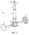
- FIG. 1 illustrates an exploded view of various components of a tilt system 10 for tilting in accordance with one or more embodiments in a vertically exploded view.
- Tilt system 10 includes one or more of a first actuator 15, a second actuator 17, a housing 9, a support member 4, a first rod 5, a second rod 7, a gearbox 6, a mounting plate 8, a nut 11, a dowel pin 19, a clevis 40, and/or other components.
- tilt system 10 may be integrated with an infant-care medical device 20, for example an incubator or baby warmer.
- Infant-care medical device 20 and/or tilt system 10 may include one or more of a tilt platform 12, an infant-supporting device 14, and/or other components.
- infant may refer to a neonate, an infant, a newborn, a baby, and/or other terms for a subject small enough to fit in an incubator or baby warmer.
- Tilt platform 12 is configured to tilt about a tilt axis 16 responsive to an adjustment of the position of support member 4.
- the adjusted position may be the longitudinal position.
- Infant-supporting device 14 may include one or more of a bed, a mattress, a pad, a blanket, and/or other suitable structure to support an infant.
- Tilt platform 12 is disposed below infant-supporting device 14 such that tilting tilt platform 12 tilts infant-supporting device 14 correspondingly.
- Housing 9 is disposed below tilt platform 12.
- Infant-care medical device 20 and/or infant-supporting device 14 include an area 14a that may be a thermo-regulated area, sterile area, and/or an area within which a suitable environment is intended to be maintained for the benefit of an infant. This suitable environment may be referred to as a micro-environment for incubators and as a macro-environment for baby-warmers. Area 14a may encompass a three-dimensional area or volume.
- tilt system 10 may be integrated in an incubator such that the thermo-regulated area may comprise the area, volume, and/or enclosure enclosed by a hood of the incubator, and/or the area under tilt platform 12. Due to tilt system 10 being compact, operation of tilt system 10 may have a small or negligible effect on thermoregulation within area 14a, in contrast to existing tilt systems. Additionally, due to compactness and placement with respect to infant-care medical device 20, use of tilt system 10 as described herein allows under-surface phototherapy as may be used to treat hyperbilirubinemia. As used herein, "under-surface” may refer to a surface of infant-supporting device 14, e.g. a baby warmer.
- first actuator 15 and/or second actuator 17 may be implemented as knobs capable of receiving actuation, e.g. in the form of rotational motion, from, e.g., a caregiver.
- Actuation of first actuator 15 and/or second actuator 17 may be transferred and/or converted to an adjustment of a position of support member 4 with respect to housing 9.
- Support member 4 is held, e.g. mechanically, by housing 9, e.g. such that support member 4 passes through housing 9.
- support member 4 is a lead screw. Other (mechanical) couplings between housing 9 and support member 4 are contemplated.
- Support member 4 may include a distal end 4a that provides support to a tilt platform to maintain a rotational orientation about a tilt axis.
- Support member 4 may be held by housing 9 such that a longitudinal position of support member 4 with respect to housing 9 is adjustable longitudinally. Adjustment of the position of support member 4 adjusts the rotational orientation of a tilt platform about its tilt axis.
- first actuator 15 may be coupled through rod 5 to gearbox 6 such that actuation received by first actuator 15 is transferred and/or converted through rod 5 to motion within gearbox 6, and, subsequently, transferred and/or converted to motion of mounting plate 8 which is coupled to gearbox 6.
- second actuator 17 may be coupled through rod 7 to gearbox 6 such that actuation received by second actuator 17 is transferred and/or converted through rod 7 to motion within gearbox 6, and, subsequently, transferred and/or converted to motion of mounting plate 8 which is coupled to gearbox 6.
- Gearbox 6 may for example be a T type bevel gearbox.
- the couplings involving gearbox 6 may be mechanical couplings.
- tilt system 10 may include two actuators that are coupled to the same rod.
- the motion of mounting plate 8 may be a rotational motion.
- Housing 9 may be coupled to gearbox 6 through mounting plate 8 such that rotational motion of mounting plate 8 may be transferred and/or converted to rotational motion of housing 9.
- Nut 11 may be affixed within and/or integrated with housing 9, such that motion of housing 9 is transferred and/or converted to an adjustment of a position, e.g. the longitudinal position, of support member 4 by virtue of matching threading between nut 11 and support member 4. In some embodiments, not depicted in FIG. 1 , the motion of mounting plate 8 may be transferred and/or converted to rotational motion of support member 4 rather than a non-rotating motion. Nut 11 may not be readily visible in a non-exploded view of tilt system 10. Support member 4 may be translating, e.g.
- support member 4 may be non-rotating.
- Support member 4 may be a trapezoidal screw.
- the various embodiments of support member 4 may be combined, for example support member 4 may be a non-rotating translating trapezoidal lead screw.
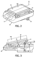
- FIG. 2 illustrates an isometric view of infant-care medical device 20 and infant-supporting device 14 in accordance with one or more embodiments.
- An infant may be placed on and/or supported by infant-supporting device 14 such that an area 14a may be a thermo-regulated area, sterile area, and/or an area within which a suitable environment is intended to be maintained for the benefit of the infant.
- Tilt platform 12 may have a center axis 22 that divides tilt platform 12 in a left half and a right half. Center axis 22 may be part of a center plane that divides infant-care medical device 20 and infant-supporting device 14 in a left half and a right half.
- Infant-care medical device 20 may include a control panel 21, which may for example be configured to control the temperature and/or other factors of the suitable environment of area 14a.
- First actuator 15 is disposed outside of area 14a and receives actuation outside of area 14a, as does a second actuator similar to second actuator 17 of FIG. 1 , the second actuator being obscured from view in FIG. 2 .
- first actuator 15 and second actuator 17 are disposed on opposite sides relative to infant-supporting device 14 such that, e.g., a caregiver may conveniently tilt tilting platform 12 from either side of infant-supporting device 14 while maintaining the integrity of the environment of area 14a.
- tilt system 10 allows single-handed adjustments to the tilt angle of tilt platform 12.
- support member 4 may be disposed a predetermined center-offset from center axis 22.
- the predetermined center-offset may be about 50 mm, about 60 mm, about 70 mm, about 80 mm, about 90 mm, about 100 mm, about 110 mm, about 120 mm, at least 80 mm, at least 100 mm, at least 120 mm, and/or another suitable distance such that under-surface phototherapy for subject 106 and/or (x-ray) photography of an area at or near center axis 22 is allowed and/or undisrupted by support member 4.
- support member 4 may be disposed a predetermined axial offset from tilt axis 16.
- the predetermined axial offset may be about 150 mm, about 160 mm, about 170 mm, about 180 mm, about 190 mm, about 200 mm, about 210 mm, about 220 mm, at least 180 mm, at least 190 mm, at least 200 mm, at least 220 mm, and/or another suitable distance such that under-surface phototherapy for subject 106 and/or (x-ray) photography of an area at or near center axis 22 is allowed and/or undisrupted by support member 4.
- known devices that provide under-surface phototherapy may range in length from about 50 cm to about 75 cm, in width from about 28 cm to about 44 cm, and in height from about 11 cm to about 16 cm.
- tilt system 10 While future devices that provide under-surface phototherapy may be more compact than the known devices, using, for support member 4, an axial offset from tilt axis 16 and/or a center-offset from center axis 22 will allow (better) under-surface phototherapy compared to using a tilt mechanism that is located centrally under a tilt platform, infant-supporting device, and/or infant-care medical device.
- a centrally-located support member 4, e.g. at or near center axis 22 and/or at or near centrally located tilt axis 16 would not leave enough space to allow under-surface phototherapy for at least some of the described known devices.
- tilt axis 6 may be located at or near one end of tilt platform 12.
- support member 4 may be disposed at or near the opposite end of tilt platform 12, at a predetermined axial offset of about 300 mm, about 325 mm, about 350 mm, about 375 mm, about 400 mm, about 450 mm, and/or another suitable distance such that use of under-surface phototherapy is allowed, for example for a baby warmer.
- support member 4, as depicted, is fully extended upward and outward of housing 9 such that tilt angle ⁇ of tilt platform 12 is currently at its positive maximum within the range of angles defined for operation of tilt system 10.
- the range of angles may be from about -30 degrees to about +30 degrees, from about -20 degrees to about +20 degrees, from about -15 degrees to about +15 degrees, from about -12 degrees to about +12 degrees, from about -10 degrees to about +10 degrees, and/or another range of degrees suitable to accomplish one or more particular benefits for infants during use.
- the range of angles may be asymmetrical around zero degrees.
- the range of angles, together with the distance between support member 4 and tilt axis 16 are factors in the required length of support member 4.
- tilt system 10 may include clevis 40, mechanically coupled to distal end 4a of support member 4, e.g. through dowel pin 19.
- Support member 4 may be mechanically coupled to the tilt platform and/or a component thereof through a pivot pin that matches clevis 40.
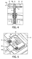
- FIG. 4 illustrates various components that may be used to couple, e.g. mechanically, support member 4 to tilt platform 12 and accommodate the movement of the point of engagement with tilt platform 12.
- clevis 40 mechanically engages a pivot pin 41.
- Clevis 40 and pivot pin 41 form one contemplated version of a manual coupler or decoupler, since the pin 41 can be disengaged from the clevis 40 without use of a tool or instrument.
- Pivot pin 41 is held within, or otherwise coupled to horizontally movable guide block 42, which can move in a direction 42a relative to the position within tilt platform 12.
- horizontally movable guide block 42 is held within a cavity, chamber, and/or other suitable enclosure of tilt platform 12 by a fixed retainer plate 43.
- a pivot pin may be coupled with the distal end of support member 4, and a matching clevis may be held within a guide block coupled to and/or held within a tilt platform similar to tilt platform 12.
- support member 4 is configured such that tilt system 10 rigidly locks at some, most, or all tilt angles within the range of tilt angles defined for operation of tilt system 10, in light of one or more of a particular coefficient of friction of support member 4 with nut 11 and/or housing 9, a maximum length of travel of support member 4 during use, a mean diameter of support member 4, a predetermined number of rotations of support member 4 to fully adjust the tilt of tilt platform 12, a maximum weight forcing down on support member 4, and/or other considerations that could be a factor in rigidly locking support member 4 such that support member 4 does not back drive. Locking in this fashion may be referred to as self-locking.
- a self-locking tilt system may not require an external and/or additional brake mechanism during operation.
- external and/or additional brake mechanisms include brake pads, spring-loaded brakes, lockable gas springs, index locking, and/or other brake mechanisms.
- a helix angle of support member 4 ranges between about 6 and about 9 degrees, between about 7 and about 8 degrees, and/or within another range suitable to rigidly lock as described herein.
- the predetermined number of rotations required to accomplish a full tilt of + 12 degrees may range between about 6 and about 9 rotations, between about 8 and about 10 rotations, between about 9 and about 11 rotations, and/or within another suitable range of rotations. In some embodiments, fewer rotations may be required by adjusting the gear ratio of gearbox 6, for example to a 1:2 ratio.
- the maximum length of travel of support member 4 depends on the predetermined distance between the point of engagement of support member 4 with tilt platform 12 and tilt axis 16, as well as the desired range of tilt angles, and/or other considerations.
- the distance between the point of engagement of support member 4 with tilt platform 12 and tilt axis 16 may be about 160 mm, about 180 mm, about 190 mm, about 200 mm, about 220 mm, between about 170 mm and about 200 mm, between about 190 mm and about 210 mm, and/or other suitable distances for a centrally located tilt axis 16, or twice such a distance for embodiments in which tilt axis 16 is disposed on the opposite end of tilt platform 12 from support member 4.
- the maximum length of travel of support member 4 during use over the defined range of angles may be about 80 mm, about 90 mm, about 100 mm, about 120 mm, between about 80 mm and about 110 mm, between about 90 mm and about 130 mm, and/or another suitable range for the maximum length of travel of support member 4 for a centrally located tilt axis 16, or twice such a length for embodiments in which tilt axis 16 is disposed on the opposite end of tilt platform 12 from support member 4.
- the pitch of support member 4 may be about 5 mm, about 6 mm, about 7 mm, about 8 mm, and/or another suitable pitch for self-locking.
- the mean diameter of support member 4 may be about 12 mm, about 14 mm, about 15 mm, about 16 mm, about 18 mm, between about 12 mm and about 14 mm, and/or another suitable diameter.
- the coefficient of friction, which may also be referred to as ⁇ , of support member 4 maybe about 0.08, about 0.1, about 0.12, about 0.14, and/or another suitable coefficient of friction.
- support member 4 may have a diameter of about 13 mm, a pitch of about 5 mm, a coefficient of friction of about 0.13, a maximum tilt of 12 degrees, and a length of travel of about 90 mm.
- a lower coefficient of friction e.g.
- the maximum weight forcing down on support member 4 during normal operation of tilt system 10 may be about 10 lbs (4.54 kg), about 15 lbs (6.80 kg), about 20 lbs (9.07 kg), about 25 lbs (11.34 kg), about 30 lbs (13.61 kg), between about 15 lbs (6.80 kg) and 25 lbs (11.34 kg), and/or another suitable weight limit that includes the tilt platform, all or some of the infant-supporting device, one or more infants, and/or other objects/components.
- the maximum torque required for operating tilt system 10 through first actuator 15 or second actuator 17 maybe about 0.1 Nm, about 0.2 Nm, about 0.3 Nm, about 0.4 Nm, about 0.5 Nm, and/or another suitable amount of torque for (manual) operation.
- tilt system may be driven by a motor, for example controlled through control panel 21.
- the maximum torque required for manual operation may not be a consideration in ease-of-use.
- FIGs. 5-7 illustrate various components related to a release mechanism to decouple tilt platform 12 from support member 4.
- clevis 40 may include an open end 40a.
- pivot pin 41 may include a segment 41 a having a reduced diameter.
- pivot pin 41 may be mechanically coupled, for example through one or more springs 51, to release actuator 50 such that release actuator 50 is movable in a direction 50a. Movement of release actuator 50 moves pivot pin 41 correspondingly such that segment 41 a of pivot pin 41 may be aligned with open end 40a of clevis 40. Responsive to such an alignment, clevis 40 may be mechanically decoupled from tilt platform 12, for example by lifting tilt platform 12 manually.
- segment 41 a and open end 40a may not be aligned.
- segment 41 a and open end 40a may be aligned to allow decoupling as described above. Easy access to tilt system 10 and/or any of its constituent components may be needed to sanitize, clean, and/or service to ensure proper operation.
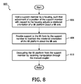
- FIG. 8 illustrates method 800 for supporting an infant within a thermo-regulated area of an infant-supporting device using a tilt system having a tilt platform disposed below the infant-supporting device that tilts about a tilt axis, a first actuator, a second actuator, a housing disposed below the tilt platform, and a support member.
- the operation of method 800 presented below is intended to be illustrative. In certain embodiments, method 800 may be accomplished with one or more additional operations not described, and/or without one or more of the operations discussed. Additionally, the order in which the operations of method 800 are illustrated in FIG. 8 and described below is not intended to be limiting.
- method 800 may be implemented using one or more processing devices (e.g., a digital processor, an analog processor, a digital circuit designed to process information, an analog circuit designed to process information, a state machine, and/or other mechanisms for electronically processing information).
- the one or more processing devices may include one or more devices executing some or all of the operations of method 800 in response to instructions stored electronically on an electronic storage medium.
- the one or more processing devices may include one or more devices configured through hardware, firmware, and/or software to be specifically designed for execution of one or more of the operations of method 800.
- a support member is held by a housing such that a position of the support member with respect to the housing is adjustable, wherein adjustment of the position of the support member with respect to the housing adjusts a rotational orientation of the tilt platform about the tilt axis.
- the adjustment of the position of the support member is accomplished through a manual coupler that couples the tilt platform to the support member.
- operation 806 is performed by a housing and nut the same as or similar to housing 9 and nut 11 (shown in FIG. 1 and described herein).
- operation 806 is performed by a manual coupler the same as or similar to the combination of clevis 40 and pivot pin 41 (shown in FIG. 4 and described herein).
- support to the tilt platform is providing by a support member to maintain the rotational orientation of the tilt platform about the tilt axis.
- operation 808 is performed by a support member the same as or similar to support member 4 (shown in FIG. 1 and described herein).
- operation 810 the tilt platform is decoupled from the support member by receiving manipulation through the manual coupler.
- operation 810 is performed by a manual coupler the same as or similar to the combination of clevis 40, pivot pin 41, and release actuator 50 (shown in FIG. 5 and described herein).
- any reference signs placed between parentheses shall not be construed as limiting the claim.
- the word “comprising” or “including” does not exclude the presence of elements or steps other than those listed in a claim.
- several of these means may be embodied by one and the same item of hardware.
- the word “a” or “an” preceding an element does not exclude the presence of a plurality of such elements.
- any device claim enumerating several means several of these means may be embodied by one and the same item of hardware.
- the mere fact that certain elements are recited in mutually different dependent claims does not indicate that these elements cannot be used in combination.
Landscapes
- Health & Medical Sciences (AREA)
- Veterinary Medicine (AREA)
- General Health & Medical Sciences (AREA)
- Public Health (AREA)
- Life Sciences & Earth Sciences (AREA)
- Animal Behavior & Ethology (AREA)
- Gynecology & Obstetrics (AREA)
- Pediatric Medicine (AREA)
- Pregnancy & Childbirth (AREA)
- Heart & Thoracic Surgery (AREA)
- Biomedical Technology (AREA)
- Engineering & Computer Science (AREA)
- Vascular Medicine (AREA)
- Accommodation For Nursing Or Treatment Tables (AREA)
- Invalid Beds And Related Equipment (AREA)
- Pivots And Pivotal Connections (AREA)
Applications Claiming Priority (2)
| Application Number | Priority Date | Filing Date | Title |
|---|---|---|---|
| IN3252CH2012 | 2012-08-08 | ||
| PCT/IB2013/055747 WO2014024062A1 (en) | 2012-08-08 | 2013-07-12 | Direct-drive tilt mechanism for infant-care medical devices |
Publications (2)
| Publication Number | Publication Date |
|---|---|
| EP2882396A1 EP2882396A1 (en) | 2015-06-17 |
| EP2882396B1 true EP2882396B1 (en) | 2016-06-29 |
Family
ID=54203590
Family Applications (1)
| Application Number | Title | Priority Date | Filing Date |
|---|---|---|---|
| EP13766701.0A Active EP2882396B1 (en) | 2012-08-08 | 2013-07-12 | Direct-drive tilt mechanism for infant-care medical devices |
Country Status (7)
Families Citing this family (2)
| Publication number | Priority date | Publication date | Assignee | Title |
|---|---|---|---|---|
| JP6268149B2 (ja) * | 2015-12-15 | 2018-01-24 | アトムメディカル株式会社 | 緩衝機能を付与した臥床台を有する保育器 |
| CN105662754A (zh) * | 2016-01-08 | 2016-06-15 | 深圳市科曼医疗设备有限公司 | 床体倾斜装置及床体倾斜的控制方法 |
Family Cites Families (15)
| Publication number | Priority date | Publication date | Assignee | Title |
|---|---|---|---|---|
| JPH01300951A (ja) * | 1988-05-26 | 1989-12-05 | Hill Rom Co Inc | 非常バイパス回路を有する二系統油圧式病院用ベッド |
| US5244452A (en) | 1991-02-15 | 1993-09-14 | Air-Shields, Inc. | Infant incubator mattress positioning assembly |
| US5531663A (en) * | 1994-11-08 | 1996-07-02 | Ohmeda Inc. | Incubator mattress tilt mechanism |
| US5624375A (en) * | 1995-04-21 | 1997-04-29 | Ohmeda Inc. | Incubator tilt mechanism |
| US6071228A (en) * | 1997-09-09 | 2000-06-06 | Hill-Rom, Inc. | Patient-support assembly for thermal support apparatus |
| US6013022A (en) * | 1998-06-29 | 2000-01-11 | Jones; Thomas C. | Tilt mechanism for infant care apparatus |
| JP2001070365A (ja) * | 1999-09-07 | 2001-03-21 | Atom Medical Corp | 開放型保育器 |
| US6880188B1 (en) * | 1999-11-15 | 2005-04-19 | Draeger Medical Infant Care, Inc. | Infant care apparatus with movable infant support |
| US6659935B2 (en) | 2000-09-21 | 2003-12-09 | Hill-Rom Services, Inc. | Lifting apparatus for patient support surface |
| CN2452482Y (zh) | 2000-11-17 | 2001-10-10 | 三丰医疗器材股份有限公司 | 可升降、倾斜及滑移的婴儿保温箱床台 |
| CN2614665Y (zh) * | 2003-05-08 | 2004-05-12 | 李小珍 | 便携式肢体温箱 |
| RU38583U1 (ru) * | 2004-02-17 | 2004-07-10 | Федеральное государственное унитарное предприятие "Производственное объединение "Уральский оптико-механический завод" | Инкубатор для новорожденных |
| CN2704351Y (zh) * | 2004-05-19 | 2005-06-15 | 陈海杰 | 用于婴儿培养箱的电动婴儿床 |
| CN201139720Y (zh) * | 2008-01-18 | 2008-10-29 | 陈再宏 | 一种婴儿辐射保暖台 |
| JP5956243B2 (ja) * | 2012-05-09 | 2016-07-27 | アトムメディカル株式会社 | 保育器 |
-
2013
- 2013-07-12 RU RU2015107843A patent/RU2640565C2/ru active
- 2013-07-12 US US14/416,459 patent/US9615985B2/en active Active
- 2013-07-12 BR BR112015002557A patent/BR112015002557A2/pt not_active Application Discontinuation
- 2013-07-12 JP JP2015525960A patent/JP6262230B2/ja active Active
- 2013-07-12 EP EP13766701.0A patent/EP2882396B1/en active Active
- 2013-07-12 CN CN201380041598.2A patent/CN104519850B/zh active Active
- 2013-07-12 WO PCT/IB2013/055747 patent/WO2014024062A1/en active Application Filing
Also Published As
| Publication number | Publication date |
|---|---|
| CN104519850B (zh) | 2018-04-27 |
| US20150202104A1 (en) | 2015-07-23 |
| EP2882396A1 (en) | 2015-06-17 |
| US9615985B2 (en) | 2017-04-11 |
| BR112015002557A2 (pt) | 2017-07-04 |
| JP2015528319A (ja) | 2015-09-28 |
| RU2015107843A (ru) | 2016-09-27 |
| RU2640565C2 (ru) | 2018-01-09 |
| CN104519850A (zh) | 2015-04-15 |
| JP6262230B2 (ja) | 2018-01-17 |
| WO2014024062A1 (en) | 2014-02-13 |
Similar Documents
| Publication | Publication Date | Title |
|---|---|---|
| US6723106B1 (en) | Surgical manipulator | |
| RU2608534C2 (ru) | Колонна для операционного стола | |
| JP6530422B2 (ja) | 能動的な付勢を伴う定荷重ばね | |
| JP6710683B2 (ja) | 患者支持システムおよびそのような患者支持システム用のレベリングシステム | |
| EP2008605A1 (en) | A hybrid manual-robotic system for controlling the position of an instrument | |
| US12150722B2 (en) | Surgical robot positioning system and related devices and methods | |
| CN218128746U (zh) | 定位装置、医疗机器人和手术导航系统 | |
| EP2882396B1 (en) | Direct-drive tilt mechanism for infant-care medical devices | |
| EP2882397B1 (en) | Direct-drive tilt mechanism for infant-care medical devices | |
| US20230110212A1 (en) | Castor base with load sensor | |
| JP6770097B2 (ja) | ロボット手術台、及び医療システム | |
| JP6023088B2 (ja) | 可動自在のヒータアセンブリを有するベッド装置 | |
| CN114587608A (zh) | 定位装置和医疗机器人 |
Legal Events
| Date | Code | Title | Description |
|---|---|---|---|
| PUAI | Public reference made under article 153(3) epc to a published international application that has entered the european phase |
Free format text: ORIGINAL CODE: 0009012 |
|
| 17P | Request for examination filed |
Effective date: 20150309 |
|
| AK | Designated contracting states |
Kind code of ref document: A1 Designated state(s): AL AT BE BG CH CY CZ DE DK EE ES FI FR GB GR HR HU IE IS IT LI LT LU LV MC MK MT NL NO PL PT RO RS SE SI SK SM TR |
|
| AX | Request for extension of the european patent |
Extension state: BA ME |
|
| DAX | Request for extension of the european patent (deleted) | ||
| GRAP | Despatch of communication of intention to grant a patent |
Free format text: ORIGINAL CODE: EPIDOSNIGR1 |
|
| INTG | Intention to grant announced |
Effective date: 20160113 |
|
| GRAS | Grant fee paid |
Free format text: ORIGINAL CODE: EPIDOSNIGR3 |
|
| GRAA | (expected) grant |
Free format text: ORIGINAL CODE: 0009210 |
|
| AK | Designated contracting states |
Kind code of ref document: B1 Designated state(s): AL AT BE BG CH CY CZ DE DK EE ES FI FR GB GR HR HU IE IS IT LI LT LU LV MC MK MT NL NO PL PT RO RS SE SI SK SM TR |
|
| REG | Reference to a national code |
Ref country code: GB Ref legal event code: FG4D |
|
| REG | Reference to a national code |
Ref country code: CH Ref legal event code: EP |
|
| REG | Reference to a national code |
Ref country code: AT Ref legal event code: REF Ref document number: 808503 Country of ref document: AT Kind code of ref document: T Effective date: 20160715 |
|
| REG | Reference to a national code |
Ref country code: IE Ref legal event code: FG4D |
|
| REG | Reference to a national code |
Ref country code: FR Ref legal event code: PLFP Year of fee payment: 4 |
|
| REG | Reference to a national code |
Ref country code: DE Ref legal event code: R096 Ref document number: 602013009009 Country of ref document: DE |
|
| REG | Reference to a national code |
Ref country code: LT Ref legal event code: MG4D |
|
| PG25 | Lapsed in a contracting state [announced via postgrant information from national office to epo] |
Ref country code: FI Free format text: LAPSE BECAUSE OF FAILURE TO SUBMIT A TRANSLATION OF THE DESCRIPTION OR TO PAY THE FEE WITHIN THE PRESCRIBED TIME-LIMIT Effective date: 20160629 Ref country code: NO Free format text: LAPSE BECAUSE OF FAILURE TO SUBMIT A TRANSLATION OF THE DESCRIPTION OR TO PAY THE FEE WITHIN THE PRESCRIBED TIME-LIMIT Effective date: 20160929 Ref country code: LT Free format text: LAPSE BECAUSE OF FAILURE TO SUBMIT A TRANSLATION OF THE DESCRIPTION OR TO PAY THE FEE WITHIN THE PRESCRIBED TIME-LIMIT Effective date: 20160629 |
|
| REG | Reference to a national code |
Ref country code: NL Ref legal event code: MP Effective date: 20160629 |
|
| PG25 | Lapsed in a contracting state [announced via postgrant information from national office to epo] |
Ref country code: GR Free format text: LAPSE BECAUSE OF FAILURE TO SUBMIT A TRANSLATION OF THE DESCRIPTION OR TO PAY THE FEE WITHIN THE PRESCRIBED TIME-LIMIT Effective date: 20160930 Ref country code: RS Free format text: LAPSE BECAUSE OF FAILURE TO SUBMIT A TRANSLATION OF THE DESCRIPTION OR TO PAY THE FEE WITHIN THE PRESCRIBED TIME-LIMIT Effective date: 20160629 Ref country code: SE Free format text: LAPSE BECAUSE OF FAILURE TO SUBMIT A TRANSLATION OF THE DESCRIPTION OR TO PAY THE FEE WITHIN THE PRESCRIBED TIME-LIMIT Effective date: 20160629 Ref country code: HR Free format text: LAPSE BECAUSE OF FAILURE TO SUBMIT A TRANSLATION OF THE DESCRIPTION OR TO PAY THE FEE WITHIN THE PRESCRIBED TIME-LIMIT Effective date: 20160629 Ref country code: LV Free format text: LAPSE BECAUSE OF FAILURE TO SUBMIT A TRANSLATION OF THE DESCRIPTION OR TO PAY THE FEE WITHIN THE PRESCRIBED TIME-LIMIT Effective date: 20160629 Ref country code: NL Free format text: LAPSE BECAUSE OF FAILURE TO SUBMIT A TRANSLATION OF THE DESCRIPTION OR TO PAY THE FEE WITHIN THE PRESCRIBED TIME-LIMIT Effective date: 20160629 |
|
| REG | Reference to a national code |
Ref country code: AT Ref legal event code: MK05 Ref document number: 808503 Country of ref document: AT Kind code of ref document: T Effective date: 20160629 |
|
| PG25 | Lapsed in a contracting state [announced via postgrant information from national office to epo] |
Ref country code: BE Free format text: LAPSE BECAUSE OF NON-PAYMENT OF DUE FEES Effective date: 20160731 |
|
| PG25 | Lapsed in a contracting state [announced via postgrant information from national office to epo] |
Ref country code: IS Free format text: LAPSE BECAUSE OF FAILURE TO SUBMIT A TRANSLATION OF THE DESCRIPTION OR TO PAY THE FEE WITHIN THE PRESCRIBED TIME-LIMIT Effective date: 20161029 Ref country code: RO Free format text: LAPSE BECAUSE OF FAILURE TO SUBMIT A TRANSLATION OF THE DESCRIPTION OR TO PAY THE FEE WITHIN THE PRESCRIBED TIME-LIMIT Effective date: 20160629 Ref country code: CZ Free format text: LAPSE BECAUSE OF FAILURE TO SUBMIT A TRANSLATION OF THE DESCRIPTION OR TO PAY THE FEE WITHIN THE PRESCRIBED TIME-LIMIT Effective date: 20160629 Ref country code: SK Free format text: LAPSE BECAUSE OF FAILURE TO SUBMIT A TRANSLATION OF THE DESCRIPTION OR TO PAY THE FEE WITHIN THE PRESCRIBED TIME-LIMIT Effective date: 20160629 Ref country code: IT Free format text: LAPSE BECAUSE OF FAILURE TO SUBMIT A TRANSLATION OF THE DESCRIPTION OR TO PAY THE FEE WITHIN THE PRESCRIBED TIME-LIMIT Effective date: 20160629 Ref country code: EE Free format text: LAPSE BECAUSE OF FAILURE TO SUBMIT A TRANSLATION OF THE DESCRIPTION OR TO PAY THE FEE WITHIN THE PRESCRIBED TIME-LIMIT Effective date: 20160629 |
|
| PG25 | Lapsed in a contracting state [announced via postgrant information from national office to epo] |
Ref country code: PT Free format text: LAPSE BECAUSE OF FAILURE TO SUBMIT A TRANSLATION OF THE DESCRIPTION OR TO PAY THE FEE WITHIN THE PRESCRIBED TIME-LIMIT Effective date: 20161031 Ref country code: PL Free format text: LAPSE BECAUSE OF FAILURE TO SUBMIT A TRANSLATION OF THE DESCRIPTION OR TO PAY THE FEE WITHIN THE PRESCRIBED TIME-LIMIT Effective date: 20160629 Ref country code: SM Free format text: LAPSE BECAUSE OF FAILURE TO SUBMIT A TRANSLATION OF THE DESCRIPTION OR TO PAY THE FEE WITHIN THE PRESCRIBED TIME-LIMIT Effective date: 20160629 Ref country code: AT Free format text: LAPSE BECAUSE OF FAILURE TO SUBMIT A TRANSLATION OF THE DESCRIPTION OR TO PAY THE FEE WITHIN THE PRESCRIBED TIME-LIMIT Effective date: 20160629 Ref country code: ES Free format text: LAPSE BECAUSE OF FAILURE TO SUBMIT A TRANSLATION OF THE DESCRIPTION OR TO PAY THE FEE WITHIN THE PRESCRIBED TIME-LIMIT Effective date: 20160629 Ref country code: BE Free format text: LAPSE BECAUSE OF FAILURE TO SUBMIT A TRANSLATION OF THE DESCRIPTION OR TO PAY THE FEE WITHIN THE PRESCRIBED TIME-LIMIT Effective date: 20160629 |
|
| REG | Reference to a national code |
Ref country code: CH Ref legal event code: PL |
|
| REG | Reference to a national code |
Ref country code: DE Ref legal event code: R097 Ref document number: 602013009009 Country of ref document: DE |
|
| PG25 | Lapsed in a contracting state [announced via postgrant information from national office to epo] |
Ref country code: CH Free format text: LAPSE BECAUSE OF NON-PAYMENT OF DUE FEES Effective date: 20160731 Ref country code: LI Free format text: LAPSE BECAUSE OF NON-PAYMENT OF DUE FEES Effective date: 20160731 |
|
| REG | Reference to a national code |
Ref country code: IE Ref legal event code: MM4A |
|
| PG25 | Lapsed in a contracting state [announced via postgrant information from national office to epo] |
Ref country code: DK Free format text: LAPSE BECAUSE OF FAILURE TO SUBMIT A TRANSLATION OF THE DESCRIPTION OR TO PAY THE FEE WITHIN THE PRESCRIBED TIME-LIMIT Effective date: 20160629 |
|
| 26N | No opposition filed |
Effective date: 20170330 |
|
| PLBE | No opposition filed within time limit |
Free format text: ORIGINAL CODE: 0009261 |
|
| STAA | Information on the status of an ep patent application or granted ep patent |
Free format text: STATUS: NO OPPOSITION FILED WITHIN TIME LIMIT |
|
| REG | Reference to a national code |
Ref country code: FR Ref legal event code: PLFP Year of fee payment: 5 |
|
| PG25 | Lapsed in a contracting state [announced via postgrant information from national office to epo] |
Ref country code: IE Free format text: LAPSE BECAUSE OF NON-PAYMENT OF DUE FEES Effective date: 20160712 |
|
| PG25 | Lapsed in a contracting state [announced via postgrant information from national office to epo] |
Ref country code: SI Free format text: LAPSE BECAUSE OF FAILURE TO SUBMIT A TRANSLATION OF THE DESCRIPTION OR TO PAY THE FEE WITHIN THE PRESCRIBED TIME-LIMIT Effective date: 20160629 Ref country code: BG Free format text: LAPSE BECAUSE OF FAILURE TO SUBMIT A TRANSLATION OF THE DESCRIPTION OR TO PAY THE FEE WITHIN THE PRESCRIBED TIME-LIMIT Effective date: 20160929 Ref country code: LU Free format text: LAPSE BECAUSE OF NON-PAYMENT OF DUE FEES Effective date: 20160712 |
|
| PG25 | Lapsed in a contracting state [announced via postgrant information from national office to epo] |
Ref country code: HU Free format text: LAPSE BECAUSE OF FAILURE TO SUBMIT A TRANSLATION OF THE DESCRIPTION OR TO PAY THE FEE WITHIN THE PRESCRIBED TIME-LIMIT; INVALID AB INITIO Effective date: 20130712 |
|
| PG25 | Lapsed in a contracting state [announced via postgrant information from national office to epo] |
Ref country code: MK Free format text: LAPSE BECAUSE OF FAILURE TO SUBMIT A TRANSLATION OF THE DESCRIPTION OR TO PAY THE FEE WITHIN THE PRESCRIBED TIME-LIMIT Effective date: 20160629 Ref country code: MT Free format text: LAPSE BECAUSE OF NON-PAYMENT OF DUE FEES Effective date: 20160731 Ref country code: CY Free format text: LAPSE BECAUSE OF FAILURE TO SUBMIT A TRANSLATION OF THE DESCRIPTION OR TO PAY THE FEE WITHIN THE PRESCRIBED TIME-LIMIT Effective date: 20160629 Ref country code: MC Free format text: LAPSE BECAUSE OF FAILURE TO SUBMIT A TRANSLATION OF THE DESCRIPTION OR TO PAY THE FEE WITHIN THE PRESCRIBED TIME-LIMIT Effective date: 20160629 |
|
| REG | Reference to a national code |
Ref country code: FR Ref legal event code: PLFP Year of fee payment: 6 |
|
| PG25 | Lapsed in a contracting state [announced via postgrant information from national office to epo] |
Ref country code: AL Free format text: LAPSE BECAUSE OF FAILURE TO SUBMIT A TRANSLATION OF THE DESCRIPTION OR TO PAY THE FEE WITHIN THE PRESCRIBED TIME-LIMIT Effective date: 20160629 Ref country code: TR Free format text: LAPSE BECAUSE OF FAILURE TO SUBMIT A TRANSLATION OF THE DESCRIPTION OR TO PAY THE FEE WITHIN THE PRESCRIBED TIME-LIMIT Effective date: 20160629 |
|
| PGFP | Annual fee paid to national office [announced via postgrant information from national office to epo] |
Ref country code: DE Payment date: 20240730 Year of fee payment: 12 |
|
| PGFP | Annual fee paid to national office [announced via postgrant information from national office to epo] |
Ref country code: GB Payment date: 20240724 Year of fee payment: 12 |
|
| PGFP | Annual fee paid to national office [announced via postgrant information from national office to epo] |
Ref country code: FR Payment date: 20240725 Year of fee payment: 12 |