EP2882272A1 - Component mounting apparatus - Google Patents
Component mounting apparatus Download PDFInfo
- Publication number
- EP2882272A1 EP2882272A1 EP12882524.7A EP12882524A EP2882272A1 EP 2882272 A1 EP2882272 A1 EP 2882272A1 EP 12882524 A EP12882524 A EP 12882524A EP 2882272 A1 EP2882272 A1 EP 2882272A1
- Authority
- EP
- European Patent Office
- Prior art keywords
- component
- sucked
- reference mark
- mounting
- refraction member
- Prior art date
- Legal status (The legal status is an assumption and is not a legal conclusion. Google has not performed a legal analysis and makes no representation as to the accuracy of the status listed.)
- Granted
Links
Images


Classifications
-
- H—ELECTRICITY
- H05—ELECTRIC TECHNIQUES NOT OTHERWISE PROVIDED FOR
- H05K—PRINTED CIRCUITS; CASINGS OR CONSTRUCTIONAL DETAILS OF ELECTRIC APPARATUS; MANUFACTURE OF ASSEMBLAGES OF ELECTRICAL COMPONENTS
- H05K13/00—Apparatus or processes specially adapted for manufacturing or adjusting assemblages of electric components
- H05K13/08—Monitoring manufacture of assemblages
- H05K13/081—Integration of optical monitoring devices in assembly lines; Processes using optical monitoring devices specially adapted for controlling devices or machines in assembly lines
- H05K13/0812—Integration of optical monitoring devices in assembly lines; Processes using optical monitoring devices specially adapted for controlling devices or machines in assembly lines the monitoring devices being integrated in the mounting machine, e.g. for monitoring components, leads, component placement
-
- H—ELECTRICITY
- H04—ELECTRIC COMMUNICATION TECHNIQUE
- H04N—PICTORIAL COMMUNICATION, e.g. TELEVISION
- H04N23/00—Cameras or camera modules comprising electronic image sensors; Control thereof
- H04N23/50—Constructional details
- H04N23/55—Optical parts specially adapted for electronic image sensors; Mounting thereof
-
- G—PHYSICS
- G02—OPTICS
- G02B—OPTICAL ELEMENTS, SYSTEMS OR APPARATUS
- G02B13/00—Optical objectives specially designed for the purposes specified below
- G02B13/001—Miniaturised objectives for electronic devices, e.g. portable telephones, webcams, PDAs, small digital cameras
- G02B13/0015—Miniaturised objectives for electronic devices, e.g. portable telephones, webcams, PDAs, small digital cameras characterised by the lens design
Definitions
- the present invention relates to a component-mounting machine which is able to capture images of an imaging reference mark provided on a component-mounting head and a component sucked by a suction nozzle simultaneously to detect a position of the sucked component with respect to the imaging reference mark.
- a component-mounting machine captures images of an imaging reference mark provided on a component-mounting head and a sucked component simultaneously, and detects positional displacement or angle deviation of the sucked component from the captured image.
- the component-mounting machine further corrects a mounting position of the sucked component based on a detected result, such as the positional displacement and the angle deviation.
- the component-mounting head is designed to move at a high speed in order to shorten the time needed for mounting components.
- the component-mounting head moves very fast, exposure time of imaging is shortened. Therefore, it is necessary to open the aperture of the camera to increase an amount of light received by the camera.
- the aperture is opened, the camera has a shallow depth of field, and thus it is difficult to focus on both the imaging reference mark and the sucked component. It is the same when sucked components having different thickness are imaged simultaneously.
- a position detection device described in PTL 1 is provided with a position marking device and an optical imaging device on a mounting head side above a component sucked by a suction pipette, and is provided with a ground glass adjacent to the component.
- the position marking device is projected on the ground glass through the optical imaging device to capture images of the position marking device and the component.
- a surface mounting machine related to a first invention described in PTL 2 includes a reference mark and a lens at a position higher than a focal position of a camera.
- the lens is able to extend the focal position of the camera upwardly up to the height of the reference mark.
- a surface mounting machine related to a second invention described in PTL 2 includes a lens which focuses the camera on the reference mark and is provided on a camera side.
- the machine also includes an actuator which moves the lens in an imaging range of the camera when the reference mark passes above the camera, and puts the lens outside the imaging range of the camera when a component for mounting passes above the camera.
- the camera described in PTL 2 uses a CCD linear sensor as an image sensor, which is able to image the component for mounting or the reference mark one-dimensionally.
- the mounting head has a complex structure since the optical imaging device is provided on the mounting head side, and thus the mounting head gets bigger and heavier.
- the optical imaging device or the ground glass is likely to collide with the component when the mounting head moves.
- the first invention described in PTL 2 has the same problem.
- the second invention described in PTL 2 moves the lens in or out of the imaging range of the camera. Thus it is impossible to capture images of the reference mark and the component for mounting simultaneously. Also, the second invention described in PTL 2 needs to drive the actuator along with the movement of a head unit having the reference mark, thus the control becomes quite complex.
- the camera described in PTL 2 uses the CCD linear sensor as the image sensor, therefore the camera cannot capture images two-dimensionally.
- a plurality of the suction nozzles is rotatably held on a circumference of a circle concentrically provided with an axis line, and the component for mounting is sucked and held by each of the suction nozzles.
- the CCD linear sensor cannot capture images of the reference mark and a plurality of the components for mounting simultaneously.
- the present invention is made in consideration of such problems, to provide a component-mounting machine which prevents collision of a sucked component with an optical system capturing images of an imaging reference mark and the sucked component simultaneously when a component-mounting head moves to capture images while lighting the component-mounting head.
- a component-mounting machine described in claim 1 includes a component-mounting head having a suction nozzle which sucks a component to mount on a substrate; and a sucked-component position detection device which captures images of an imaging reference mark provided on the component-mounting head and a component sucked by the suction nozzle simultaneously to detect a position of the sucked component with respect to the imaging reference mark, wherein the sucked-component position detection device includes an imaging unit, which is provided on a base side of the component-mounting machine and has an image sensor and a lens; and a first refraction member which alters a focal position of a first optical path that connects the image sensor, the lens and the imaging reference mark, and the first refraction member is provided on the base side and at a position lower than a focal position of a second optical path that connects the image sensor, the lens and the sucked component.
- a component-mounting machine described in claim 2 is the component-mounting machine of claim 1, wherein the sucked-component position detection device further includes a second refraction member which alters the focal position of the second optical path, and the second refraction member is provided on the base side and at a position lower than the focal position of the second optical path.
- a component-mounting machine described in claim 3 is the component-mounting machine of claim 2, wherein the component-mounting head is a rotary head in which a plurality of the suction nozzles is rotatably held on a circumference of a circle concentrically provided with an axis line, and a plurality of the second refraction members is concentrically arranged in accordance with a height of the sucked components on the plurality of the component-mounting heads which have different circumferential diameters.
- a component-mounting machine described in claim 4 is the component-mounting machine of any one of claims 1 to 3, wherein the sucked-component position detection device includes a light source which irradiates the imaging reference mark and the sucked component with light, and the first refraction member is provided on an imaging unit side than the light source.
- a component-mounting machine described in claim 5 is the component-mounting machine of any one of claims 1 to 4, wherein the sucked-component position detection device further includes a light source which irradiates the imaging reference mark and the sucked components with light, and the imaging unit has an aperture which is set such that, out of reflective light emitted from the light source and reflected by the imaging reference mark and the sucked component, mainly light parallel to a height direction of the component-mounting machine arrives at the image sensor.
- the sucked-component position detection device includes the first refraction member which alters the focal position of the first optical path that connects the image sensor, the lens and the imaging reference mark. Therefore, it is possible to alter the focal position of the first optical path with respect to the imaging reference mark arranged at a height different from that of the sucked component, and to focus on both the imaging reference mark and the sucked component. Moreover, since the first refraction member is provided at a position lower than the focal position of the second optical path that connects the image sensor, the lens and the sucked component, the first refraction member and the sucked component do not collide with each other when the component-mounting head moves to capture images.
- the first refraction member is provided on the base side of the component-mounting machine, a configuration of the component-mounting head can be further simplified as compared with a case in which the first refraction member is provided on the component-mounting head side, thereby lightening the component-mounting head.
- the second refraction member is provided to alter the focal position of the second optical path, it is possible to alter the focal position of the second optical path in accordance with a height of the sucked component. Moreover, since the second refraction member is provided on the base side and at a position lower than the focal position of the second optical path, it is possible to obtain a similar effect to the aforementioned effect of the first refraction member.
- the plurality of the second refraction members is concentrically arranged in accordance with a height of the sucked components on the plurality of the component-mounting heads having different circumferential diameters around which the suction nozzles rotate. Therefore, it is possible to set the focal position of the second optical path in accordance with a height of the sucked component of each component-mounting head, respectively. Moreover, it is unnecessary to replace the second refraction member every time the component-mounting head is replaced, thereby decreasing manhours.
- the first refraction member is provided on the imaging unit side than the light source that irradiates the imaging reference mark and the sucked component with light. Therefore, it is possible to prevent the light, emitted from the light source, from being guided directly to the first refraction member and being reflected by the first refraction member. Thus, it is possible to prevent the reflective light from causing an adverse effect on imaging of the imaging reference mark and the sucked component.
- the imaging unit has an aperture which is set such that, out of reflective light emitted from the light source and reflected by the imaging reference mark and the sucked component, mainly light parallel to a height direction of the component-mounting machine arrives at the image sensor. Therefore, it is possible to suppress a ghost occurrence in the captured images of the imaging reference mark and the sucked component, thereby preventing false recognition when the positions of the imaging reference mark and the sucked component are recognized.
- Fig. 1 is a perspective view expressing an example of the component-mounting machine.
- a conveying direction of the substrate is a traverse direction (indicated by arrow X)
- a direction perpendicular to the traverse direction (indicated by arrow X) within a horizontal plane is a longitudinal direction (indicated by arrow Y).
- a normal direction of the horizontal plane is a height direction (indicated by arrow Z).
- the component-mounting machine 1 includes a substrate conveying device 3, a component feeding device 4, a component transfer device 5, a sucked-component position detection device 6 and a control device 7, which are mounted on a base 8.
- the base 8 is movably loaded in the longitudinal direction (indicated by arrow Y) with respect to a system base 2.
- the substrate conveying device 3 carries the substrate into and out of a mounting position.
- the substrate conveying device 3 is a so-called double conveyor type transfer device, which is installed around a center of the longitudinal direction (indicated by arrow Y) of the component-mounting machine 1, and in which a first conveying device 31 and a second conveying device 32 are arranged side by side.
- the first conveying device 31 has a pair of guide rails arranged parallel to the traverse direction (indicated by arrow X) on the base 8, and a pair of conveyor belts which is directed to the pair of the guide rails and transfers the substrate loaded thereon.
- the first conveying device 31 is provided with a clamp device (not shown), which positions the substrate transferred to the mounting position by lifting the substrate from a side of the base 8.
- the second conveying device 32 has a configuration similar to the first conveying device 31.
- the component feeding device 4 is provided on a front end (left side of paper of Fig. 1 ) of the longitudinal direction (indicated by arrow Y) of the component-mounting machine 1, and has a plurality of cassette feeders 41 detachably mounted on a feeder holder.
- the feeder 41 includes a feeder main body 42, a feeding reel 43 which is rotatably and detachably mounted to the feeder main body 42, and a component feeding unit 44 which is installed on a tip side (near to the center of the component-mounting machine 1) of the feeder main body 42.
- the feeding reel 43 is a carrier for feeding the component, and includes a carrier tape (not shown) wound thereon, which holds a predetermined number of components at regular intervals. A front edge of the carrier tape is drawn to the component feeding unit 44, thereby feeding different component for each carrier tape.
- the feeder 41 is able to feed, for example, relatively small components such as a chip component.
- the component transfer device 5 sucks the component from the component feeding device 4 to mount the component on the substrate carried into the mounting position.
- the component transfer device 5 is a so-called XY robot type transfer device, which is movable in the traverse direction (indicated by arrow X) and in the longitudinal direction (indicated by arrow Y).
- the component transfer device 5 is installed above the component feeding device 4 from a rear end (right back side of paper of Fig. 1 ) of the longitudinal direction (indicated by arrow Y) of the component-mounting machine 1 to a front end (left front side of paper of Fig. 1 ) of the same direction.
- the component transfer device 5 has a head driving mechanism 51 and a component-mounting head 52.
- the head driving mechanism 51 is able to drive the component-mounting head 52 in the traverse direction (indicated by arrow X) and in the longitudinal direction (indicated by arrow Y).
- the component-mounting head 52 has a plurality of suction nozzles 53. Each of the suction nozzles 53 sucks the component by its apical portion to mount the component on the substrate carried into the mounting position. Moreover, since the first conveying device 31 and the second conveying device 32 alternately carry the substrate in and out, it is possible to alternately mount the component using the component transfer device 5.
- the base 8, between the component feeding device 4 and the substrate conveying device 3, is provided with the sucked-component position detection device 6 thereon, which detects a held position of the component.
- the sucked-component position detection device 6 is able to detect positional displacement or angle deviation of the component (hereinafter "sucked component PA”) sucked by the suction nozzle 53.
- the detection results, i.e. positional displacement and angle deviation, are used for calibrating the mounting position of the sucked component PA.
- the sucked-component position detection device 6 will hereinafter be described in detail.
- the component-mounting machine 1 can be controlled by the control device 7 installed on a front upper part of a cover.
- the control device 7 has a CPU and a memory (both not shown), and is able to drive the component-mounting machine 1 by executing a component mounting program stored in the memory. That is, the control device 7 drives the substrate conveying device 3, the component feeding device 4, the component transfer device 5 and the sucked-component position detection device 6 on a basis of the component mounting program, thereby mounting the component on the substrate.
- the head driving mechanism 51 is driven to cause the component-mounting head 52 to move to the component feeding device 4.
- the plurality of the suction nozzles 53 sucks the component, respectively.
- the head driving mechanism 51 is driven to cause the component-mounting head 52 to move.
- images of the sucked component PA and an imaging reference mark 5M (described later) are captured simultaneously.
- the component-mounting head 52 moves above the substrate position at the predetermined position.
- a moving position of the component-mounting head 52 is calibrated based on positional displacement and angle deviation, which have been detected by the sucked-component position detection device 6.
- the component-mounting head 52 mounts the component on the substrate, and then returns back to the component feeding device 4.
- the component-mounting machine 1 is able to mount a plurality of the components on the substrate by repeating this series of operations.
- the sucked-component position detection device 6 detects a position of the sucked component PA with respect to the imaging reference mark 5M by simultaneously imaging the imaging reference mark 5M provided on the component-mounting head 52 and the sucked component PA sucked by the suction nozzle 53.
- Fig. 2 is a configuration diagram schematically expressing an example of the sucked-component position detection device.
- the component-mounting head 52 is installed as two component-mounting heads 52a and 52d, having different circumferential diameters around which the suction nozzles 53 rotate.
- the suction nozzle 53 of the component-mounting head 52a is indicated as the suction nozzle 531, and the sucked component PA sucked by the suction nozzle 531 is indicated as the sucked component PA1.
- the suction nozzle 53 of the component-mounting head 52d is indicated as the suction nozzle 534, and the sucked component PA sucked by the suction nozzle 534 is indicated as the sucked component PA2.
- the term of "sucked component PA" is properly used for illustrating a case in which the sucked components PA1 and PA2 are not distinguished.
- the imaging reference mark 5M is a reflective member which reflects light emitted by a light source 64.
- a plurality of the imaging reference marks 5M (for example, four marks) are arranged in the traverse direction (indicated by arrow X) and in the longitudinal direction (indicated by arrow Y) at regular intervals.
- the imaging reference marks 5M are installed on outer circumferential sides of the component-mounting heads 52a and 52d, and at a position higher than the sucked components PA1 and PA2 in the height direction (indicated by arrow Z). Therefore, it is possible to prevent the other components which have been mounted from colliding with the imaging reference marks 5M when the component-mounting head 52a and 52d move above the substrate.
- the sucked-component position detection device 6 includes an imaging unit 61, a first refraction member 62, a second refraction member 63, a light source 64 and an image processing unit 65.
- the image processing unit 65 may be installed in the control device 7.
- the imaging unit 61 is installed on the side of the base 8 (a side of a direction indicated by arrow Z1 in Fig. 2 ) of the component-mounting machine 1 shown in Fig. 1 .
- the imaging unit 61 uses, for example, a publicly-known CCD camera or a publicly-known CMOS camera.
- the imaging unit 61 has an image sensor 611, a lens 612, and an aperture.
- the image sensor 611 is a charge-coupled device (CCD)
- CMOS complementary metal oxide semiconductor
- the image sensor 611 is a 2D image sensor, and is constituted of a plurality of light-receiving elements which is arranged in a plane. Therefore, the imaging unit 61 has a two-dimensional visual field. Thus, the imaging unit 61 is able to pick up the imaging reference mark 5M and the sucked component PA1 held by each of the rotating suction nozzles 531 in the same visual field, thereby simultaneously imaging the imaging reference mark 5M and the sucked component PA1.
- This configuration is not limited to the sucked component PA1, but can be employed for other sucked components PA.
- the lens 612 it is possible to use a publicly-known collecting lens, or to configure an optical system by combining a plurality of convex lenses and concave lenses.
- the lens 612 uses an aspheric lens with decreased spherical aberration or a low dispersion lens which decreases chromatic aberration by lowering light dispersion.
- the focal length of the lens 612 is set such that the lens 612 focuses on the sucked component PA1.
- the sucked component PA1 is at the lowest position (height) in the height direction (indicated by arrow Z), among the sucked components PA.
- the first refraction member 62 is a refraction member which alters a focal position FP1 of a first optical path OP1.
- a cylindrical optical glass is employed as the first refraction member 62.
- the first refraction member 62 may use various kinds of lenses, such as a plastic lens, a fluorite lens or an aspheric lens, other than the glass, as long as it can alter the focal position FP1 of the first optical path OP1.
- the first optical path OP1 is an optical path which connects the image sensor 611, the lens 612 and the imaging reference mark 5M. As shown in Fig. 2 , when the light is irradiated on the imaging reference mark 5M from the light source 64 (indicated by arrow L10), reflective light reflected by the imaging reference mark 5M passes through the first refraction member 62 and the lens 612 to arrive at the image sensor 611. In Fig. 2 , the first optical path OP1 is schematically indicated by arrows L11 to L13.
- a focal position on the side of the imaging reference mark 5M is indicated as a focal position FP1 of the first optical path OP1
- a focal position on the side of the image sensor 611 is indicated as a focal position FP0 of the same.
- the focal position FP0 corresponds to a reference position of the height direction (indicated by arrow Z).
- the first refraction member 62 is installed on the side of the base 8 (a side of the direction indicated by arrow Z1) and at a position lower than a focal position FP2 of a second optical path OP2.
- the first refraction member 62 is loaded on an outer circumferential side of the lens 612.
- the second optical path OP2 is an optical path which connects the image sensor 611, the lens 612 and the sucked component PA1.
- Fig. 2 when the light is irradiated on the sucked component PA1 from the light source 64 (indicated by arrow L20), reflective light reflected by the sucked component PA1 passes through the lens 612 to arrive at the image sensor 611.
- Fig. 2 when the light is irradiated on the sucked component PA1 from the light source 64 (indicated by arrow L20), reflective light reflected by the sucked component PA1 passes through the lens 612 to arrive at the image sensor 611.
- the second optical path OP2 is schematically indicated by arrows L21 and L22. Moreover, in the second optical path OP2, a focal position on the side of the sucked component PA1 is indicated as the focal position FP2 of the second optical path OP2. A focal position on the side of the image sensor 611 is the same as the focal position FP0.
- the first optical path OP1 When the first refraction member 62 is disposed between the imaging reference mark 5M and the lens 612, the first optical path OP1 has the optical length longer than the optical length when the first refraction member 62 is not disposed. That is, the focal position FP1 of the first optical path OP1 is set to a position higher than the focal position FP2 of the second optical path OP2 in the height direction (indicated by arrow Z). Therefore, it is possible to focus on the imaging reference mark 5M which is installed above the sucked component PA1 in the height direction (indicated by arrow Z). Thus, it is possible to focus on both the imaging reference mark 5M and the sucked component PA1 to simultaneously capture images of the imaging reference mark 5M and the sucked component PA1 in the same visual field.
- the sucked-component position detection device 6 includes the first refraction member 62 for altering the focal position FP1 of the first optical path OP1 that connects the image sensor 611, the lens 612 and the imaging reference mark 5M. Therefore, it is possible to alter the focal position FP1 of the first optical path OP1 with respect to the imaging reference mark 5M installed at a height different than that of the sucked component PA1, thereby focusing on both the imaging reference mark 5M and the sucked component PA1.
- the first refraction member 62 Since the first refraction member 62 is installed at a position lower than the focal position FP2 of the second optical path OP2 that connects the image sensor 611, the lens 612 and the sucked component PA1, the first refraction member 62 and the sucked component PA1 do not collide with each other when the component-mounting head 52a moves to capture images in the longitudinal direction (indicated by arrow Y1) of Fig. 2 . Therefore, it is not necessary to provide a mechanism for preventing collision of the first refraction member 62 with the sucked component PA1, thereby downsizing the sucked-component position detection device 6.
- This configuration is not limited to the sucked component PA1, but can be employed for other sucked components PA.
- the first refraction member 62 is provided on the side of the base 8 (a side of the direction indicated by arrow Z1) of the component-mounting machine 1, a configuration of the component-mounting head 52a can be more simplified as compared with a case in which the first refraction member 62 is provided on the side of the component-mounting head 52a, thereby lightening the component-mounting head 52a.
- the sucked-component position detection device 6 may include the second refraction member 63.
- the second refraction member 63 is a refraction member which alters the focal position FP2 of the second optical path OP2, and can be formed by the same material as the first refraction member 62.
- the second refraction member 63 may be installed on the side of the base 8 (a side of the direction indicated by arrow Z1) and at a position lower than a focal position FP2 of a second optical path OP2.
- the second refraction member 63 is loaded on the lens 612, which is on an inner circumferential side than the first refraction member 62. As shown in Fig.
- the second optical path OP2 is indicated as the second optical path OP21.
- the second optical path OP21 is schematically indicated by arrows L31 to L33.
- the sucked component PA2 is positioned above the sucked component PA1 in the height direction (indicated by arrow Z).
- the second optical path OP2 has the optical length longer than the optical length when the second refraction member 63 is not disposed. That is, the focal position FP21 of the second optical path OP21 is set to a position higher than the focal position FP2 of the second optical path OP2 in the height direction (indicated by arrow Z). Therefore, it is possible to focus on the sucked component PA2 which is positioned above the sucked component PA1 in the height direction (indicated by arrow Z).
- the imaging reference mark 5M is installed above any one of the sucked components PA in the height direction (indicated by arrow Z)
- the thickness T63 of the second refraction member 63 is set to be thinner than the thickness T62 of the first refraction member 62.
- the aperture of the imaging unit 61 is set such that, out of reflective light emitted from the light source 64 and reflected by the imaging reference mark 5M and the sucked component PA, mainly the light parallel to the height direction (indicated by arrow Z1) of the component-mounting machine 1 arrives at the image sensor 611. Therefore, it is possible to suppress a ghost occurrence in the captured images of the imaging reference mark 5M and the sucked component PA, thereby preventing false recognition when the positions of imaging reference mark 5M and the sucked component PA are recognized.
- the sucked-component position detection device 6 includes the second refraction member 63 which alters the focal position FP2 of the second optical path OP2, thus it is possible to alter the focal position FP2 of the second optical path OP2 in accordance with a height of the sucked component PA2. Since the second refraction member 63 is installed on the side of the base 8 (a side of the direction indicated by arrow Z1) and at a position lower than a focal position FP2 of a second optical path OP2, it is possible to obtain a similar effect to the aforementioned effect of the first refraction member 62.
- the component-mounting head 52 of the present embodiment is a rotary head in which a plurality of the suction nozzles 53 is rotatably held on a circumference of a circle concentrically provided with an axis line.
- the rotary head has a different circumferential diameter around which the suction nozzle 53 rotates depending on a size of the sucked component PA.
- the rotary head for mounting a big-size sucked component PA keeps an interval between the sucked components PA by making the circumferential diameter around which the suction nozzle 53 rotates bigger as compared with the rotary head for mounting a small-size sucked component PA.
- the sucked components PA sucked by the suction nozzles 53 may be different.
- the thickness of the sucked components PA will be different, thus the positions (heights) of the sucked components PA in the height direction (indicated by arrow Z) will be different.
- three second refraction members 63 are concentrically arranged as viewed from the height direction (indicated by arrow Z1) in accordance with heights of the sucked components PA held by three component-mounting heads 52b to 52d, having different circumferential diameters around which the suction nozzles 53 rotate.
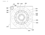
- Fig. 3 is a plan view illustrating a state in what three second refraction members are concentrically arranged.
- the three second refraction members 63 are distinguished such that the second refraction member 63 arranged on an outermost circumferential side is indicated as the second refraction member 631, the second refraction member 63 arranged on an inner circumferential side of the second refraction member 631 is indicated as the second refraction member 632, and the second refraction member 63 arranged on an inner circumferential side of the second refraction member 632 is indicated as the second refraction member 633.
- the first refraction member 62 and the second refraction members 631 to 633 are loaded on the lens 612.
- the visual field of the imaging unit 61 is indicated as a region VF1.
- the symbols 52a, 52b, 52c and 52d are allocated in a descending order of greatness of circumferential diameter around which the suction nozzle 53 rotates.
- the component-mounting heads 52a, 52b, 52c and 52d have the suction nozzles 531, 532, 533 and 534, respectively.
- the circumference around which the suction nozzle 531 rotates is a circumference 541
- the circumference around which the suction nozzle 532 rotates is a circumference 542
- the circumference around which the suction nozzle 533 rotates is a circumference 543
- the circumference around which the suction nozzle 534 rotates is a circumference 544.
- the component-mounting heads 52a and 52d are illustrated while the component-mounting heads 52b and 52c are omitted.
- the second refraction member 631 has the focal position FP2 of the second optical path OP2, which is set in accordance with the height of the sucked component PA held by the component-mounting head 52b.
- the second refraction member 632 has the focal position FP2 of the second optical path OP2, which is set in accordance with the height of the sucked component PA held by the component-mounting head 52c.
- the second refraction member 633 has the focal position FP2 of the second optical path OP2, which is set in accordance with the height of the sucked component PA2 held by the component-mounting head 52d.
- the focal length of the lens 612 is set in accordance with the height of the sucked component PA1 held by the component-mounting head 52a.
- the second refraction member 63 is not necessary.
- three second refraction members 631 to 633 are concentrically arranged in accordance with heights of the sucked components PA held by three component-mounting heads 52b to 52d, having different circumferential diameters around which the suction nozzles 53 rotate. Therefore, it is possible to set the focal position FP2 of the second optical path OP2 in accordance with heights of the sucked components PA of each of the component-mounting heads 52b to 52d, respectively. Moreover, it is unnecessary to replace the second refraction member 63 every time the component-mounting head 52 is replaced, thereby decreasing manhours.
- the light source 64 can irradiate the imaging reference mark 5M and the sucked component PA with light.
- a publicly-known light-emitting diode (LED) may be used, and wavelength of the emitted light is not limited.
- the control device 7 outputs an imaging-start signal to the imaging unit 61 and the light source 64.
- the imaging-start signal is output, the light source 64 irradiates the imaging reference mark 5M and the sucked component PA with light during an exposure time of the imaging unit 61.
- the imaging unit 61 captures images of the imaging reference mark 5M and the sucked component PA simultaneously.
- the imaging unit 61 captures images of the imaging reference mark 5M and the sucked component PA simultaneously.
- the imaging unit 61 has the aperture which is set such that, out of reflective light emitted from the light source 64 and reflected by the imaging reference mark 5M and the sucked component PA1, mainly the light parallel to the height direction (indicated by arrow Z1) of the component-mounting machine 1 arrives at the image sensor 611. Therefore, it is possible to suppress a ghost occurred in the captured images of the imaging reference mark 5M and the sucked component PA1, thereby preventing false recognition when the positions of imaging reference mark 5M and the sucked component PA1 are recognized.
- the first refraction member 62 and the second refraction member 63 are installed on the side of the imaging unit 61 rather than the light source 64 which irradiates the imaging reference mark 5M and the sucked component PA with light. Therefore, it is possible to prevent the light, emitted from the light source 64, from being guided directly to the first refraction member 62 and the second refraction member 63 and being reflected by the first refraction member 62 and second refraction member 63. Thus, it is possible to prevent the reflective light from causing an adverse effect on imaging of the imaging reference mark 5M and the sucked component PA.
- the image processing unit 65 processes the images of the imaging reference mark 5M and the sucked component PA, which are captured by the imaging unit 61, and calculates the position of the sucked component PA with respect to the imaging reference mark 5M.
- the memory of the control device 7 stores a legitimate holding position of each sucked component PA with respect to the imaging reference mark 5M in advance.
- the image processing unit 65 matches the imaging reference mark 5M stored in the memory and the imaging reference mark 5M captured by the imaging unit 61.
- the image processing unit 65 calculates positional displacement and angle deviation of each sucked component PA by comparing the legitimate holding position stored in the memory and a holding position captured by the imaging unit 61. Based on the calculated results, such as positional displacement and angle deviation, the mounting position of the sucked component PA is calibrated.
- the present invention is not limited to embodiment as stated above and illustrated in accompanying drawings, but may be modified and implemented appropriately without departing from the scope of the invention.
- the embodiment shows three second refraction members 63 which are concentrically arranged.
- a number of the second refraction members 63 is not limited to 3; it can be appropriately modified in accordance with a circumferential diameter around which the suction nozzle 53 rotates.
- a shape of the second refraction member 63 is not limited to a concentric circle.
- cylindrical second refraction members 63 may be scattered on a portion corresponding to the suction nozzles 532 to 534 as shown in Fig. 3 .
- three second refraction members 631 to 633 are loaded on the lens 612.
- the second refraction member 63 may be replaced at the same time.
Landscapes
- Engineering & Computer Science (AREA)
- Physics & Mathematics (AREA)
- Operations Research (AREA)
- Manufacturing & Machinery (AREA)
- Microelectronics & Electronic Packaging (AREA)
- Multimedia (AREA)
- Signal Processing (AREA)
- General Physics & Mathematics (AREA)
- Optics & Photonics (AREA)
- Supply And Installment Of Electrical Components (AREA)
- Length Measuring Devices By Optical Means (AREA)
Abstract
Description
- The present invention relates to a component-mounting machine which is able to capture images of an imaging reference mark provided on a component-mounting head and a component sucked by a suction nozzle simultaneously to detect a position of the sucked component with respect to the imaging reference mark.
- A component-mounting machine captures images of an imaging reference mark provided on a component-mounting head and a sucked component simultaneously, and detects positional displacement or angle deviation of the sucked component from the captured image. The component-mounting machine further corrects a mounting position of the sucked component based on a detected result, such as the positional displacement and the angle deviation.
- Moreover, in the component-mounting machine, the component-mounting head is designed to move at a high speed in order to shorten the time needed for mounting components. When the component-mounting head moves very fast, exposure time of imaging is shortened. Therefore, it is necessary to open the aperture of the camera to increase an amount of light received by the camera. However, if the aperture is opened, the camera has a shallow depth of field, and thus it is difficult to focus on both the imaging reference mark and the sucked component. It is the same when sucked components having different thickness are imaged simultaneously.
- As an invention related to such a task, for example, inventions described in
Patent Literatures PTL 1 is provided with a position marking device and an optical imaging device on a mounting head side above a component sucked by a suction pipette, and is provided with a ground glass adjacent to the component. The position marking device is projected on the ground glass through the optical imaging device to capture images of the position marking device and the component. - A surface mounting machine related to a first invention described in
PTL 2 includes a reference mark and a lens at a position higher than a focal position of a camera. The lens is able to extend the focal position of the camera upwardly up to the height of the reference mark. Furthermore, a surface mounting machine related to a second invention described inPTL 2 includes a lens which focuses the camera on the reference mark and is provided on a camera side. The machine also includes an actuator which moves the lens in an imaging range of the camera when the reference mark passes above the camera, and puts the lens outside the imaging range of the camera when a component for mounting passes above the camera. Moreover, the camera described inPTL 2 uses a CCD linear sensor as an image sensor, which is able to image the component for mounting or the reference mark one-dimensionally. -
- PTL 1:
JP-T-2001-518723 - PTL 2:
JP-A-2005-197564 - However, in the invention described in
PTL 1, the mounting head has a complex structure since the optical imaging device is provided on the mounting head side, and thus the mounting head gets bigger and heavier. The optical imaging device or the ground glass is likely to collide with the component when the mounting head moves. Regarding the former, the first invention described inPTL 2 has the same problem. - The second invention described in
PTL 2 moves the lens in or out of the imaging range of the camera. Thus it is impossible to capture images of the reference mark and the component for mounting simultaneously. Also, the second invention described inPTL 2 needs to drive the actuator along with the movement of a head unit having the reference mark, thus the control becomes quite complex. - Furthermore, the camera described in
PTL 2 uses the CCD linear sensor as the image sensor, therefore the camera cannot capture images two-dimensionally. For example, in the rotary head, a plurality of the suction nozzles is rotatably held on a circumference of a circle concentrically provided with an axis line, and the component for mounting is sucked and held by each of the suction nozzles. In this case, the CCD linear sensor cannot capture images of the reference mark and a plurality of the components for mounting simultaneously. - The present invention is made in consideration of such problems, to provide a component-mounting machine which prevents collision of a sucked component with an optical system capturing images of an imaging reference mark and the sucked component simultaneously when a component-mounting head moves to capture images while lighting the component-mounting head.
- A component-mounting machine described in
claim 1 includes a component-mounting head having a suction nozzle which sucks a component to mount on a substrate; and a sucked-component position detection device which captures images of an imaging reference mark provided on the component-mounting head and a component sucked by the suction nozzle simultaneously to detect a position of the sucked component with respect to the imaging reference mark, wherein the sucked-component position detection device includes an imaging unit, which is provided on a base side of the component-mounting machine and has an image sensor and a lens; and a first refraction member which alters a focal position of a first optical path that connects the image sensor, the lens and the imaging reference mark, and the first refraction member is provided on the base side and at a position lower than a focal position of a second optical path that connects the image sensor, the lens and the sucked component. - A component-mounting machine described in
claim 2 is the component-mounting machine ofclaim 1, wherein the sucked-component position detection device further includes a second refraction member which alters the focal position of the second optical path, and the second refraction member is provided on the base side and at a position lower than the focal position of the second optical path. - A component-mounting machine described in
claim 3 is the component-mounting machine ofclaim 2, wherein the component-mounting head is a rotary head in which a plurality of the suction nozzles is rotatably held on a circumference of a circle concentrically provided with an axis line, and a plurality of the second refraction members is concentrically arranged in accordance with a height of the sucked components on the plurality of the component-mounting heads which have different circumferential diameters. - A component-mounting machine described in
claim 4 is the component-mounting machine of any one ofclaims 1 to 3, wherein the sucked-component position detection device includes a light source which irradiates the imaging reference mark and the sucked component with light, and the first refraction member is provided on an imaging unit side than the light source. - A component-mounting machine described in
claim 5 is the component-mounting machine of any one ofclaims 1 to 4, wherein the sucked-component position detection device further includes a light source which irradiates the imaging reference mark and the sucked components with light, and the imaging unit has an aperture which is set such that, out of reflective light emitted from the light source and reflected by the imaging reference mark and the sucked component, mainly light parallel to a height direction of the component-mounting machine arrives at the image sensor. Advantageous - According to the component-mounting machine described in
claim 1, the sucked-component position detection device includes the first refraction member which alters the focal position of the first optical path that connects the image sensor, the lens and the imaging reference mark. Therefore, it is possible to alter the focal position of the first optical path with respect to the imaging reference mark arranged at a height different from that of the sucked component, and to focus on both the imaging reference mark and the sucked component. Moreover, since the first refraction member is provided at a position lower than the focal position of the second optical path that connects the image sensor, the lens and the sucked component, the first refraction member and the sucked component do not collide with each other when the component-mounting head moves to capture images. Therefore, it is not necessary to provide a mechanism for preventing collision of the first refraction member with the sucked component, thereby downsizing the sucked-component position detection device. Moreover, since the first refraction member is provided on the base side of the component-mounting machine, a configuration of the component-mounting head can be further simplified as compared with a case in which the first refraction member is provided on the component-mounting head side, thereby lightening the component-mounting head. - According to the component-mounting machine described in
claim 2, since the second refraction member is provided to alter the focal position of the second optical path, it is possible to alter the focal position of the second optical path in accordance with a height of the sucked component. Moreover, since the second refraction member is provided on the base side and at a position lower than the focal position of the second optical path, it is possible to obtain a similar effect to the aforementioned effect of the first refraction member. - According to the component-mounting machine described in
claim 3, the plurality of the second refraction members is concentrically arranged in accordance with a height of the sucked components on the plurality of the component-mounting heads having different circumferential diameters around which the suction nozzles rotate. Therefore, it is possible to set the focal position of the second optical path in accordance with a height of the sucked component of each component-mounting head, respectively. Moreover, it is unnecessary to replace the second refraction member every time the component-mounting head is replaced, thereby decreasing manhours. - According to the component-mounting machine described in
claim 4, the first refraction member is provided on the imaging unit side than the light source that irradiates the imaging reference mark and the sucked component with light. Therefore, it is possible to prevent the light, emitted from the light source, from being guided directly to the first refraction member and being reflected by the first refraction member. Thus, it is possible to prevent the reflective light from causing an adverse effect on imaging of the imaging reference mark and the sucked component. - According to the component-mounting machine described in
claim 5, the imaging unit has an aperture which is set such that, out of reflective light emitted from the light source and reflected by the imaging reference mark and the sucked component, mainly light parallel to a height direction of the component-mounting machine arrives at the image sensor. Therefore, it is possible to suppress a ghost occurrence in the captured images of the imaging reference mark and the sucked component, thereby preventing false recognition when the positions of the imaging reference mark and the sucked component are recognized. -
- [
Fig. 1] Fig. 1 is a perspective view expressing an example of the component-mounting machine. - [
Fig. 2] Fig. 2 is a configuration diagram schematically expressing an example of the sucked-component position detection device. - [
Fig. 3] Fig. 3 is a plan view illustrating a state in what three second refraction members are concentrically arranged. - Hereinafter, embodiments of the present invention will be described based on accompanying drawings. Each diagram is a conceptual diagram, and does not define the size of detailed structures.
-
Fig. 1 is a perspective view expressing an example of the component-mounting machine. InFig. 1 , a conveying direction of the substrate is a traverse direction (indicated by arrow X), and a direction perpendicular to the traverse direction (indicated by arrow X) within a horizontal plane is a longitudinal direction (indicated by arrow Y). Moreover, a normal direction of the horizontal plane is a height direction (indicated by arrow Z). The component-mountingmachine 1 includes asubstrate conveying device 3, acomponent feeding device 4, acomponent transfer device 5, a sucked-componentposition detection device 6 and acontrol device 7, which are mounted on abase 8. Thebase 8 is movably loaded in the longitudinal direction (indicated by arrow Y) with respect to asystem base 2. - The
substrate conveying device 3 carries the substrate into and out of a mounting position. Thesubstrate conveying device 3 is a so-called double conveyor type transfer device, which is installed around a center of the longitudinal direction (indicated by arrow Y) of the component-mountingmachine 1, and in which a first conveyingdevice 31 and a second conveyingdevice 32 are arranged side by side. The first conveyingdevice 31 has a pair of guide rails arranged parallel to the traverse direction (indicated by arrow X) on thebase 8, and a pair of conveyor belts which is directed to the pair of the guide rails and transfers the substrate loaded thereon. The first conveyingdevice 31 is provided with a clamp device (not shown), which positions the substrate transferred to the mounting position by lifting the substrate from a side of thebase 8. The second conveyingdevice 32 has a configuration similar to the first conveyingdevice 31. - The
component feeding device 4 is provided on a front end (left side of paper ofFig. 1 ) of the longitudinal direction (indicated by arrow Y) of the component-mountingmachine 1, and has a plurality ofcassette feeders 41 detachably mounted on a feeder holder. Thefeeder 41 includes a feedermain body 42, a feedingreel 43 which is rotatably and detachably mounted to the feedermain body 42, and acomponent feeding unit 44 which is installed on a tip side (near to the center of the component-mounting machine 1) of the feedermain body 42. The feedingreel 43 is a carrier for feeding the component, and includes a carrier tape (not shown) wound thereon, which holds a predetermined number of components at regular intervals. A front edge of the carrier tape is drawn to thecomponent feeding unit 44, thereby feeding different component for each carrier tape. Thefeeder 41 is able to feed, for example, relatively small components such as a chip component. - The
component transfer device 5 sucks the component from thecomponent feeding device 4 to mount the component on the substrate carried into the mounting position. Thecomponent transfer device 5 is a so-called XY robot type transfer device, which is movable in the traverse direction (indicated by arrow X) and in the longitudinal direction (indicated by arrow Y). Thecomponent transfer device 5 is installed above thecomponent feeding device 4 from a rear end (right back side of paper ofFig. 1 ) of the longitudinal direction (indicated by arrow Y) of the component-mountingmachine 1 to a front end (left front side of paper ofFig. 1 ) of the same direction. Thecomponent transfer device 5 has ahead driving mechanism 51 and a component-mountinghead 52. - The
head driving mechanism 51 is able to drive the component-mountinghead 52 in the traverse direction (indicated by arrow X) and in the longitudinal direction (indicated by arrow Y). The component-mountinghead 52 has a plurality ofsuction nozzles 53. Each of thesuction nozzles 53 sucks the component by its apical portion to mount the component on the substrate carried into the mounting position. Moreover, since the first conveyingdevice 31 and the second conveyingdevice 32 alternately carry the substrate in and out, it is possible to alternately mount the component using thecomponent transfer device 5. - The
base 8, between thecomponent feeding device 4 and thesubstrate conveying device 3, is provided with the sucked-componentposition detection device 6 thereon, which detects a held position of the component. The sucked-componentposition detection device 6 is able to detect positional displacement or angle deviation of the component (hereinafter "sucked component PA") sucked by thesuction nozzle 53. The detection results, i.e. positional displacement and angle deviation, are used for calibrating the mounting position of the sucked component PA. The sucked-componentposition detection device 6 will hereinafter be described in detail. - The component-mounting
machine 1 can be controlled by thecontrol device 7 installed on a front upper part of a cover. Thecontrol device 7 has a CPU and a memory (both not shown), and is able to drive the component-mountingmachine 1 by executing a component mounting program stored in the memory. That is, thecontrol device 7 drives thesubstrate conveying device 3, thecomponent feeding device 4, thecomponent transfer device 5 and the sucked-componentposition detection device 6 on a basis of the component mounting program, thereby mounting the component on the substrate. - The
head driving mechanism 51 is driven to cause the component-mountinghead 52 to move to thecomponent feeding device 4. The plurality of thesuction nozzles 53 sucks the component, respectively. When everysuction nozzle 53 has sucked the component, thehead driving mechanism 51 is driven to cause the component-mountinghead 52 to move. When the component-mountinghead 52 arrives above the sucked-componentposition detection device 6, images of the sucked component PA and animaging reference mark 5M (described later) are captured simultaneously. Then, the component-mountinghead 52 moves above the substrate position at the predetermined position. At this time, a moving position of the component-mountinghead 52 is calibrated based on positional displacement and angle deviation, which have been detected by the sucked-componentposition detection device 6. The component-mountinghead 52 mounts the component on the substrate, and then returns back to thecomponent feeding device 4. The component-mountingmachine 1 is able to mount a plurality of the components on the substrate by repeating this series of operations. - The sucked-component
position detection device 6 detects a position of the sucked component PA with respect to theimaging reference mark 5M by simultaneously imaging theimaging reference mark 5M provided on the component-mountinghead 52 and the sucked component PA sucked by thesuction nozzle 53.Fig. 2 is a configuration diagram schematically expressing an example of the sucked-component position detection device. InFig. 2 , the component-mountinghead 52 is installed as two component-mountingheads suction nozzles 53 rotate. Thesuction nozzle 53 of the component-mountinghead 52a is indicated as thesuction nozzle 531, and the sucked component PA sucked by thesuction nozzle 531 is indicated as the sucked component PA1. Similarly, thesuction nozzle 53 of the component-mountinghead 52d is indicated as thesuction nozzle 534, and the sucked component PA sucked by thesuction nozzle 534 is indicated as the sucked component PA2. In the present description, the term of "sucked component PA" is properly used for illustrating a case in which the sucked components PA1 and PA2 are not distinguished. - The
imaging reference mark 5M is a reflective member which reflects light emitted by alight source 64. A plurality of the imaging reference marks 5M (for example, four marks) are arranged in the traverse direction (indicated by arrow X) and in the longitudinal direction (indicated by arrow Y) at regular intervals. As shown inFig. 2 , the imaging reference marks 5M are installed on outer circumferential sides of the component-mountingheads head position detection device 6 includes animaging unit 61, afirst refraction member 62, asecond refraction member 63, alight source 64 and animage processing unit 65. Theimage processing unit 65 may be installed in thecontrol device 7. - The
imaging unit 61 is installed on the side of the base 8 (a side of a direction indicated by arrow Z1 inFig. 2 ) of the component-mountingmachine 1 shown inFig. 1 . Theimaging unit 61 uses, for example, a publicly-known CCD camera or a publicly-known CMOS camera. Theimaging unit 61 has animage sensor 611, alens 612, and an aperture. When the CCD camera is employed, theimage sensor 611 is a charge-coupled device (CCD), and when the CMOS camera is employed, theimage sensor 611 is a complementary metal oxide semiconductor (CMOS). - The
image sensor 611 is a 2D image sensor, and is constituted of a plurality of light-receiving elements which is arranged in a plane. Therefore, theimaging unit 61 has a two-dimensional visual field. Thus, theimaging unit 61 is able to pick up theimaging reference mark 5M and the sucked component PA1 held by each of therotating suction nozzles 531 in the same visual field, thereby simultaneously imaging theimaging reference mark 5M and the sucked component PA1. This configuration is not limited to the sucked component PA1, but can be employed for other sucked components PA. - As the
lens 612, it is possible to use a publicly-known collecting lens, or to configure an optical system by combining a plurality of convex lenses and concave lenses. For example, thelens 612 uses an aspheric lens with decreased spherical aberration or a low dispersion lens which decreases chromatic aberration by lowering light dispersion. The focal length of thelens 612 is set such that thelens 612 focuses on the sucked component PA1. The sucked component PA1 is at the lowest position (height) in the height direction (indicated by arrow Z), among the sucked components PA. - The
first refraction member 62 is a refraction member which alters a focal position FP1 of a first optical path OP1. For example, a cylindrical optical glass is employed as thefirst refraction member 62. Thefirst refraction member 62 may use various kinds of lenses, such as a plastic lens, a fluorite lens or an aspheric lens, other than the glass, as long as it can alter the focal position FP1 of the first optical path OP1. - The first optical path OP1 is an optical path which connects the
image sensor 611, thelens 612 and theimaging reference mark 5M. As shown inFig. 2 , when the light is irradiated on theimaging reference mark 5M from the light source 64 (indicated by arrow L10), reflective light reflected by theimaging reference mark 5M passes through thefirst refraction member 62 and thelens 612 to arrive at theimage sensor 611. InFig. 2 , the first optical path OP1 is schematically indicated by arrows L11 to L13. In the first optical path OP1, a focal position on the side of theimaging reference mark 5M is indicated as a focal position FP1 of the first optical path OP1, and a focal position on the side of theimage sensor 611 is indicated as a focal position FP0 of the same. In the sucked-componentposition detection device 6, the focal position FP0 corresponds to a reference position of the height direction (indicated by arrow Z). - The
first refraction member 62 is installed on the side of the base 8 (a side of the direction indicated by arrow Z1) and at a position lower than a focal position FP2 of a second optical path OP2. In this embodiment, thefirst refraction member 62 is loaded on an outer circumferential side of thelens 612. The second optical path OP2 is an optical path which connects theimage sensor 611, thelens 612 and the sucked component PA1. As shown inFig. 2 , when the light is irradiated on the sucked component PA1 from the light source 64 (indicated by arrow L20), reflective light reflected by the sucked component PA1 passes through thelens 612 to arrive at theimage sensor 611. InFig. 2 , the second optical path OP2 is schematically indicated by arrows L21 and L22. Moreover, in the second optical path OP2, a focal position on the side of the sucked component PA1 is indicated as the focal position FP2 of the second optical path OP2. A focal position on the side of theimage sensor 611 is the same as the focal position FP0. - When the
first refraction member 62 is disposed between theimaging reference mark 5M and thelens 612, the first optical path OP1 has the optical length longer than the optical length when thefirst refraction member 62 is not disposed. That is, the focal position FP1 of the first optical path OP1 is set to a position higher than the focal position FP2 of the second optical path OP2 in the height direction (indicated by arrow Z). Therefore, it is possible to focus on theimaging reference mark 5M which is installed above the sucked component PA1 in the height direction (indicated by arrow Z). Thus, it is possible to focus on both theimaging reference mark 5M and the sucked component PA1 to simultaneously capture images of theimaging reference mark 5M and the sucked component PA1 in the same visual field. - In the present embodiment, the sucked-component
position detection device 6 includes thefirst refraction member 62 for altering the focal position FP1 of the first optical path OP1 that connects theimage sensor 611, thelens 612 and theimaging reference mark 5M. Therefore, it is possible to alter the focal position FP1 of the first optical path OP1 with respect to theimaging reference mark 5M installed at a height different than that of the sucked component PA1, thereby focusing on both theimaging reference mark 5M and the sucked component PA1. - Since the
first refraction member 62 is installed at a position lower than the focal position FP2 of the second optical path OP2 that connects theimage sensor 611, thelens 612 and the sucked component PA1, thefirst refraction member 62 and the sucked component PA1 do not collide with each other when the component-mountinghead 52a moves to capture images in the longitudinal direction (indicated by arrow Y1) ofFig. 2 . Therefore, it is not necessary to provide a mechanism for preventing collision of thefirst refraction member 62 with the sucked component PA1, thereby downsizing the sucked-componentposition detection device 6. This configuration is not limited to the sucked component PA1, but can be employed for other sucked components PA. - Since the
first refraction member 62 is provided on the side of the base 8 (a side of the direction indicated by arrow Z1) of the component-mountingmachine 1, a configuration of the component-mountinghead 52a can be more simplified as compared with a case in which thefirst refraction member 62 is provided on the side of the component-mountinghead 52a, thereby lightening the component-mountinghead 52a. - The sucked-component
position detection device 6 may include thesecond refraction member 63. Thesecond refraction member 63 is a refraction member which alters the focal position FP2 of the second optical path OP2, and can be formed by the same material as thefirst refraction member 62. Thesecond refraction member 63 may be installed on the side of the base 8 (a side of the direction indicated by arrow Z1) and at a position lower than a focal position FP2 of a second optical path OP2. In the present embodiment, thesecond refraction member 63 is loaded on thelens 612, which is on an inner circumferential side than thefirst refraction member 62. As shown inFig. 2 , when the light is irradiated on the sucked component PA2 from the light source 64 (indicated by arrow L30), reflective light reflected by the sucked component PA2 passes through thesecond refraction member 63 and thelens 612 to arrive at theimage sensor 611. In this case, the second optical path OP2 is indicated as the second optical path OP21. InFig. 2 , the second optical path OP21 is schematically indicated by arrows L31 to L33. - As shown in
Fig. 2 , the sucked component PA2 is positioned above the sucked component PA1 in the height direction (indicated by arrow Z). When thesecond refraction member 63 is disposed between the sucked component PA2 and thelens 612, the second optical path OP2 has the optical length longer than the optical length when thesecond refraction member 63 is not disposed. That is, the focal position FP21 of the second optical path OP21 is set to a position higher than the focal position FP2 of the second optical path OP2 in the height direction (indicated by arrow Z). Therefore, it is possible to focus on the sucked component PA2 which is positioned above the sucked component PA1 in the height direction (indicated by arrow Z). Thus, it is possible to focus on both theimaging reference mark 5M and the sucked component PA2 to simultaneously capture images of theimaging reference mark 5M and the sucked component PA2 in the same visual field. Since theimaging reference mark 5M is installed above any one of the sucked components PA in the height direction (indicated by arrow Z), the thickness T63 of thesecond refraction member 63 is set to be thinner than the thickness T62 of thefirst refraction member 62. - There is light that arrives at the
image sensor 611 not via thefirst refraction member 62 among the reflective light reflected by theimaging reference mark 5M, and light that arrives at theimage sensor 611 not via thesecond refraction member 63 among the reflective light reflected by the sucked component PA2. Due to these rays of light, a ghost may occur in the captured image. In the sucked-componentposition detection device 6 of the present embodiment, the aperture of theimaging unit 61 is set such that, out of reflective light emitted from thelight source 64 and reflected by theimaging reference mark 5M and the sucked component PA, mainly the light parallel to the height direction (indicated by arrow Z1) of the component-mountingmachine 1 arrives at theimage sensor 611. Therefore, it is possible to suppress a ghost occurrence in the captured images of theimaging reference mark 5M and the sucked component PA, thereby preventing false recognition when the positions ofimaging reference mark 5M and the sucked component PA are recognized. - In the present embodiment, the sucked-component
position detection device 6 includes thesecond refraction member 63 which alters the focal position FP2 of the second optical path OP2, thus it is possible to alter the focal position FP2 of the second optical path OP2 in accordance with a height of the sucked component PA2. Since thesecond refraction member 63 is installed on the side of the base 8 (a side of the direction indicated by arrow Z1) and at a position lower than a focal position FP2 of a second optical path OP2, it is possible to obtain a similar effect to the aforementioned effect of thefirst refraction member 62. - The component-mounting
head 52 of the present embodiment is a rotary head in which a plurality of thesuction nozzles 53 is rotatably held on a circumference of a circle concentrically provided with an axis line. The rotary head has a different circumferential diameter around which thesuction nozzle 53 rotates depending on a size of the sucked component PA. For example, the rotary head for mounting a big-size sucked component PA keeps an interval between the sucked components PA by making the circumferential diameter around which thesuction nozzle 53 rotates bigger as compared with the rotary head for mounting a small-size sucked component PA. Since the rotary head has the plurality of thesuction nozzles 53, the sucked components PA sucked by thesuction nozzles 53 may be different. When the sucked components PA are different, the thickness of the sucked components PA will be different, thus the positions (heights) of the sucked components PA in the height direction (indicated by arrow Z) will be different. - That is, when the component-mounting
heads 52 are different from each other, the circumferential diameters around which thesuction nozzles 53 rotate will be different, and heights of the sucked components PA will be different. Therefore, it is necessary to set the focal position FP2 of the second optical path OP2 in accordance with the component-mountinghead 52. In the present embodiment, threesecond refraction members 63 are concentrically arranged as viewed from the height direction (indicated by arrow Z1) in accordance with heights of the sucked components PA held by three component-mounting heads 52b to 52d, having different circumferential diameters around which thesuction nozzles 53 rotate. -
Fig. 3 is a plan view illustrating a state in what three second refraction members are concentrically arranged. InFig. 3 , the threesecond refraction members 63 are distinguished such that thesecond refraction member 63 arranged on an outermost circumferential side is indicated as thesecond refraction member 631, thesecond refraction member 63 arranged on an inner circumferential side of thesecond refraction member 631 is indicated as thesecond refraction member 632, and thesecond refraction member 63 arranged on an inner circumferential side of thesecond refraction member 632 is indicated as thesecond refraction member 633. Thefirst refraction member 62 and thesecond refraction members 631 to 633 are loaded on thelens 612. The visual field of theimaging unit 61 is indicated as a region VF1. - In the case of the component-mounting
heads 52a to 52d, thesymbols suction nozzle 53 rotates. The component-mountingheads suction nozzles Fig. 3 , the circumference around which thesuction nozzle 531 rotates is acircumference 541, the circumference around which thesuction nozzle 532 rotates is acircumference 542, the circumference around which thesuction nozzle 533 rotates is acircumference 543, and the circumference around which thesuction nozzle 534 rotates is acircumference 544. InFig. 2 , the component-mountingheads - The
second refraction member 631 has the focal position FP2 of the second optical path OP2, which is set in accordance with the height of the sucked component PA held by the component-mounting head 52b. Thesecond refraction member 632 has the focal position FP2 of the second optical path OP2, which is set in accordance with the height of the sucked component PA held by the component-mounting head 52c. Thesecond refraction member 633 has the focal position FP2 of the second optical path OP2, which is set in accordance with the height of the sucked component PA2 held by the component-mountinghead 52d. As stated above, the focal length of thelens 612 is set in accordance with the height of the sucked component PA1 held by the component-mountinghead 52a. When the component-mountinghead 52a is used, thesecond refraction member 63 is not necessary. - In the present embodiment, three
second refraction members 631 to 633 are concentrically arranged in accordance with heights of the sucked components PA held by three component-mounting heads 52b to 52d, having different circumferential diameters around which thesuction nozzles 53 rotate. Therefore, it is possible to set the focal position FP2 of the second optical path OP2 in accordance with heights of the sucked components PA of each of the component-mounting heads 52b to 52d, respectively. Moreover, it is unnecessary to replace thesecond refraction member 63 every time the component-mountinghead 52 is replaced, thereby decreasing manhours. - The
light source 64 can irradiate theimaging reference mark 5M and the sucked component PA with light. As thelight source 64, for examples, a publicly-known light-emitting diode (LED) may be used, and wavelength of the emitted light is not limited. As shown inFig. 2 , when the component-mountinghead 52 arrives above the sucked-componentposition detection device 6, thecontrol device 7 outputs an imaging-start signal to theimaging unit 61 and thelight source 64. When the imaging-start signal is output, thelight source 64 irradiates theimaging reference mark 5M and the sucked component PA with light during an exposure time of theimaging unit 61. Theimaging unit 61 captures images of theimaging reference mark 5M and the sucked component PA simultaneously. - While the component-mounting
head 52 moves in the longitudinal direction (indicated by arrow Y1) without stopping above the sucked-componentposition detection unit 6, theimaging unit 61 captures images of theimaging reference mark 5M and the sucked component PA simultaneously. At this time, theimaging unit 61 has the aperture which is set such that, out of reflective light emitted from thelight source 64 and reflected by theimaging reference mark 5M and the sucked component PA1, mainly the light parallel to the height direction (indicated by arrow Z1) of the component-mountingmachine 1 arrives at theimage sensor 611. Therefore, it is possible to suppress a ghost occurred in the captured images of theimaging reference mark 5M and the sucked component PA1, thereby preventing false recognition when the positions ofimaging reference mark 5M and the sucked component PA1 are recognized. - In the present embodiment, the
first refraction member 62 and thesecond refraction member 63 are installed on the side of theimaging unit 61 rather than thelight source 64 which irradiates theimaging reference mark 5M and the sucked component PA with light. Therefore, it is possible to prevent the light, emitted from thelight source 64, from being guided directly to thefirst refraction member 62 and thesecond refraction member 63 and being reflected by thefirst refraction member 62 andsecond refraction member 63. Thus, it is possible to prevent the reflective light from causing an adverse effect on imaging of theimaging reference mark 5M and the sucked component PA. - The
image processing unit 65 processes the images of theimaging reference mark 5M and the sucked component PA, which are captured by theimaging unit 61, and calculates the position of the sucked component PA with respect to theimaging reference mark 5M. The memory of thecontrol device 7 stores a legitimate holding position of each sucked component PA with respect to theimaging reference mark 5M in advance. Theimage processing unit 65 matches theimaging reference mark 5M stored in the memory and theimaging reference mark 5M captured by theimaging unit 61. Theimage processing unit 65 calculates positional displacement and angle deviation of each sucked component PA by comparing the legitimate holding position stored in the memory and a holding position captured by theimaging unit 61. Based on the calculated results, such as positional displacement and angle deviation, the mounting position of the sucked component PA is calibrated. - The present invention is not limited to embodiment as stated above and illustrated in accompanying drawings, but may be modified and implemented appropriately without departing from the scope of the invention. For example, the embodiment shows three
second refraction members 63 which are concentrically arranged. However, a number of thesecond refraction members 63 is not limited to 3; it can be appropriately modified in accordance with a circumferential diameter around which thesuction nozzle 53 rotates. - Moreover, a shape of the
second refraction member 63 is not limited to a concentric circle. For example, cylindricalsecond refraction members 63 may be scattered on a portion corresponding to thesuction nozzles 532 to 534 as shown inFig. 3 . In the embodiment, threesecond refraction members 631 to 633 are loaded on thelens 612. However, it is possible to load thesecond refraction member 63 corresponding to the used component-mountinghead 52 on thelens 612. When the component-mountinghead 52 is replaced, thesecond refraction member 63 may be replaced at the same time. -
- 1: component-mounting machine,
- 52: component-mounting head,
- 53: suction nozzle, 5M: imaging reference mark,
- 6: sucked-component position detection unit,
- 61: imaging unit, 611: image sensor, 612: lens,
- 62: first refraction member,
- 63: second refraction member,
- 64: light source,
- OP1: first optical path, OP2: second optical path,
Claims (5)
- A component-mounting machine, comprising:a component-mounting head having a suction nozzle which sucks a component to mount on a substrate; anda sucked-component position detection device which captures images of an imaging reference mark provided on the component-mounting head and the sucked component by the suction nozzle simultaneously to detect a position of the sucked component with respect to the imaging reference mark,wherein the sucked-component position detection device includes an imaging unit which is provided on a base side of the component-mounting machine and has an image sensor and a lens; and a first refraction member which alters a focal position of a first optical path that connects the image sensor, the lens and the imaging reference mark, andthe first refraction member is provided on the base side and at a position lower than a focal position of a second optical path that connects the image sensor, the lens, and the sucked component.
- The component-mounting machine according to Claim 1,
wherein the sucked-component position detection device further includes a second refraction member which alters the focal position of the second optical path, and
the second refraction member is provided on the base side and at a position lower than the focal position of the second optical path. - The component-mounting machine according to Claim 2,
wherein the component-mounting head is a rotary head in which a plurality of the suction nozzles are rotatably held on a circumference of a circle concentrically provided with an axis line, and
a plurality of the second refraction members are concentrically arranged in accordance with a height of a plurality of the sucked components on a plurality of the component-mounting heads which have different circumferential diameters. - The component-mounting machine according to any one of Claims 1 to 3,
wherein the sucked-component position detection device includes a light source which irradiates the imaging reference mark and the sucked component with light, and
the first refraction member is provided on an imaging unit side rather than a light source side. - The component-mounting machine according to any one of Claims 1 to 4,
wherein the sucked-component position detection device includes a light source which irradiates the imaging reference mark and the sucked components with light, and
the imaging unit has an aperture which is set such that, out of reflective light emitted from the light source and reflected by the imaging reference mark and the sucked component, mainly light parallel to a height direction of the component-mounting machine arrives at the image sensor.
Applications Claiming Priority (1)
| Application Number | Priority Date | Filing Date | Title |
|---|---|---|---|
| PCT/JP2012/069630 WO2014020733A1 (en) | 2012-08-01 | 2012-08-01 | Component mounting apparatus |
Publications (3)
| Publication Number | Publication Date |
|---|---|
| EP2882272A1 true EP2882272A1 (en) | 2015-06-10 |
| EP2882272A4 EP2882272A4 (en) | 2015-07-29 |
| EP2882272B1 EP2882272B1 (en) | 2020-05-06 |
Family
ID=50027463
Family Applications (1)
| Application Number | Title | Priority Date | Filing Date |
|---|---|---|---|
| EP12882524.7A Active EP2882272B1 (en) | 2012-08-01 | 2012-08-01 | Component mounting apparatus |
Country Status (5)
| Country | Link |
|---|---|
| US (1) | US9438777B2 (en) |
| EP (1) | EP2882272B1 (en) |
| JP (1) | JP6138127B2 (en) |
| CN (1) | CN104509235B (en) |
| WO (1) | WO2014020733A1 (en) |
Cited By (1)
| Publication number | Priority date | Publication date | Assignee | Title |
|---|---|---|---|---|
| EP3506728A4 (en) * | 2016-08-24 | 2019-08-14 | Fuji Corporation | MOUNTING DEVICE |
Families Citing this family (9)
| Publication number | Priority date | Publication date | Assignee | Title |
|---|---|---|---|---|
| JPH0717372B2 (en) | 1986-10-31 | 1995-03-01 | 田中貴金属工業株式会社 | Method for producing gold cyanide salt |
| US10070570B2 (en) * | 2015-03-10 | 2018-09-04 | Fuji Corporation | Mounting device, image processing method, and imaging unit |
| CN108029243B (en) * | 2015-07-06 | 2020-04-03 | 株式会社富士 | Mounting device, photographing processing method, and photographing unit |
| CN105392356B (en) * | 2015-12-04 | 2018-10-09 | 深圳市瓦力自动化有限公司 | A kind of combination accurate positioning device and its method |
| CN110870400B (en) * | 2017-07-18 | 2021-07-23 | 株式会社富士 | Component mounting machine and illumination light quantity adjustment method for the component mounting machine |
| DE102018210737B3 (en) * | 2018-06-29 | 2019-11-14 | Asm Assembly Systems Gmbh & Co. Kg | Functional element for a placement machine, placement machine and method for determining a position of a functional element |
| CN111669961A (en) * | 2019-03-06 | 2020-09-15 | 苏州旭创科技有限公司 | Suction nozzle for automatic chip mounter and automatic chip mounter |
| JP7546232B2 (en) * | 2019-12-11 | 2024-09-06 | パナソニックIpマネジメント株式会社 | Component imaging device and component mounting device |
| JP7766014B2 (en) * | 2021-09-30 | 2025-11-07 | 芝浦メカトロニクス株式会社 | Tiling Device |
Family Cites Families (15)
| Publication number | Priority date | Publication date | Assignee | Title |
|---|---|---|---|---|
| JPH0222899A (en) * | 1988-07-12 | 1990-01-25 | Tdk Corp | Device for recognizing position of component |
| JPH0831715B2 (en) * | 1990-02-20 | 1996-03-27 | 松下電工株式会社 | Position correction method for leaded parts |
| JP3535828B2 (en) | 1997-09-30 | 2004-06-07 | シーメンス アクチエンゲゼルシヤフト | Method and apparatus for detecting position of lead terminal and / or edge of component |
| WO2002017357A2 (en) * | 2000-08-22 | 2002-02-28 | Agilent Technologies, Inc. | Three dimensional inspection of leaded ics |
| JP2002094296A (en) * | 2000-09-13 | 2002-03-29 | Fuji Mach Mfg Co Ltd | Suction nozzle, method for detecting holding position of electric component, method for detecting curvature of suction tube, method for specifying rotational position of suction nozzle, and electric component handling unit |
| JP2004094567A (en) * | 2002-08-30 | 2004-03-25 | Matsushita Electric Ind Co Ltd | Image reading apparatus and image reading method |
| JP4234402B2 (en) * | 2002-11-21 | 2009-03-04 | 富士機械製造株式会社 | Electronic circuit component image acquisition device |
| JP2005127836A (en) * | 2003-10-23 | 2005-05-19 | Yamaha Motor Co Ltd | Component recognition method, component recognition device, surface mounter, component test device, and board inspection device |
| JP4343710B2 (en) | 2004-01-09 | 2009-10-14 | ヤマハ発動機株式会社 | Surface mount machine |
| JP4354845B2 (en) * | 2004-02-25 | 2009-10-28 | Juki株式会社 | Electronic component mounting device |
| JP4789721B2 (en) * | 2006-07-11 | 2011-10-12 | 富士機械製造株式会社 | Electronic circuit component holding position detection device using a component holder |
| JP4851361B2 (en) * | 2007-02-19 | 2012-01-11 | 富士機械製造株式会社 | Electronic circuit component mounting device |
| JP5373657B2 (en) * | 2010-02-09 | 2013-12-18 | ヤマハ発動機株式会社 | Component mounting apparatus and component mounting method |
| JP2011233674A (en) | 2010-04-27 | 2011-11-17 | Hitachi High-Tech Instruments Co Ltd | Method for mounting electronic component and electronic component mounter |
| JP6008946B2 (en) | 2012-04-12 | 2016-10-19 | 富士機械製造株式会社 | Component mounter |
-
2012
- 2012-08-01 EP EP12882524.7A patent/EP2882272B1/en active Active
- 2012-08-01 JP JP2014527903A patent/JP6138127B2/en active Active
- 2012-08-01 US US14/417,649 patent/US9438777B2/en active Active
- 2012-08-01 CN CN201280075011.5A patent/CN104509235B/en active Active
- 2012-08-01 WO PCT/JP2012/069630 patent/WO2014020733A1/en not_active Ceased
Cited By (2)
| Publication number | Priority date | Publication date | Assignee | Title |
|---|---|---|---|---|
| EP3506728A4 (en) * | 2016-08-24 | 2019-08-14 | Fuji Corporation | MOUNTING DEVICE |
| US10736251B2 (en) | 2016-08-24 | 2020-08-04 | Fuji Corporation | Mounting device |
Also Published As
| Publication number | Publication date |
|---|---|
| WO2014020733A1 (en) | 2014-02-06 |
| CN104509235A (en) | 2015-04-08 |
| JPWO2014020733A1 (en) | 2016-07-11 |
| US20150222794A1 (en) | 2015-08-06 |
| EP2882272B1 (en) | 2020-05-06 |
| CN104509235B (en) | 2017-04-26 |
| JP6138127B2 (en) | 2017-05-31 |
| EP2882272A4 (en) | 2015-07-29 |
| US9438777B2 (en) | 2016-09-06 |
Similar Documents
| Publication | Publication Date | Title |
|---|---|---|
| EP2882272B1 (en) | Component mounting apparatus | |
| JP6880114B2 (en) | Component operating device | |
| JP6999691B2 (en) | Component receiver with optical sensor | |
| EP2838333B1 (en) | Component mounting machine | |
| KR101562692B1 (en) | Components mounting device | |
| JP6460600B2 (en) | Detection device | |
| WO2014147701A1 (en) | Component mounting device and method of calibration in component mounting device | |
| JP6124918B2 (en) | Component mounting machine and mounting inspection machine | |
| JP2015194530A (en) | Alignment method of photoelectric conversion element, and fluid injector | |
| JP4234402B2 (en) | Electronic circuit component image acquisition device | |
| EP2925112B1 (en) | Component mounting machine | |
| JP5875676B2 (en) | Imaging apparatus and image processing apparatus | |
| JPWO2020170328A1 (en) | Parts mounting machine | |
| US11310951B2 (en) | Substrate working device and component mounting device | |
| JP2006140391A (en) | Component recognition device and component mounting device | |
| JP6830316B2 (en) | Detection device | |
| JP4783335B2 (en) | Component recognition device, surface mounter | |
| CN106937525B (en) | Image generation device, installation device, and image generation method | |
| EP3264071A1 (en) | Inspection device and inspection method | |
| JP4047012B2 (en) | IMAGING DEVICE AND ELECTRICAL COMPONENT MOUNTING SYSTEM PROVIDED WITH IT |
Legal Events
| Date | Code | Title | Description |
|---|---|---|---|
| PUAI | Public reference made under article 153(3) epc to a published international application that has entered the european phase |
Free format text: ORIGINAL CODE: 0009012 |
|
| 17P | Request for examination filed |
Effective date: 20150127 |
|
| AK | Designated contracting states |
Kind code of ref document: A1 Designated state(s): AL AT BE BG CH CY CZ DE DK EE ES FI FR GB GR HR HU IE IS IT LI LT LU LV MC MK MT NL NO PL PT RO RS SE SI SK SM TR |
|
| AX | Request for extension of the european patent |
Extension state: BA ME |
|
| RA4 | Supplementary search report drawn up and despatched (corrected) |
Effective date: 20150629 |
|
| RIC1 | Information provided on ipc code assigned before grant |
Ipc: H05K 13/04 20060101AFI20150623BHEP Ipc: H05K 13/08 20060101ALI20150623BHEP |
|
| DAX | Request for extension of the european patent (deleted) | ||
| RAP1 | Party data changed (applicant data changed or rights of an application transferred) |
Owner name: FUJI CORPORATION |
|
| RIN1 | Information on inventor provided before grant (corrected) |
Inventor name: YOSHINO TOMOHARU Inventor name: YAMAKAGE YUSUKE |
|
| STAA | Information on the status of an ep patent application or granted ep patent |
Free format text: STATUS: EXAMINATION IS IN PROGRESS |
|
| 17Q | First examination report despatched |
Effective date: 20190605 |
|
| GRAP | Despatch of communication of intention to grant a patent |
Free format text: ORIGINAL CODE: EPIDOSNIGR1 |
|
| STAA | Information on the status of an ep patent application or granted ep patent |
Free format text: STATUS: GRANT OF PATENT IS INTENDED |
|
| INTG | Intention to grant announced |
Effective date: 20200107 |
|
| GRAS | Grant fee paid |
Free format text: ORIGINAL CODE: EPIDOSNIGR3 |
|
| GRAA | (expected) grant |
Free format text: ORIGINAL CODE: 0009210 |
|
| STAA | Information on the status of an ep patent application or granted ep patent |
Free format text: STATUS: THE PATENT HAS BEEN GRANTED |
|
| AK | Designated contracting states |
Kind code of ref document: B1 Designated state(s): AL AT BE BG CH CY CZ DE DK EE ES FI FR GB GR HR HU IE IS IT LI LT LU LV MC MK MT NL NO PL PT RO RS SE SI SK SM TR |
|
| REG | Reference to a national code |
Ref country code: GB Ref legal event code: FG4D |
|
| REG | Reference to a national code |
Ref country code: CH Ref legal event code: EP Ref country code: AT Ref legal event code: REF Ref document number: 1268969 Country of ref document: AT Kind code of ref document: T Effective date: 20200515 |
|
| REG | Reference to a national code |
Ref country code: IE Ref legal event code: FG4D |
|
| REG | Reference to a national code |
Ref country code: DE Ref legal event code: R096 Ref document number: 602012070014 Country of ref document: DE |
|
| REG | Reference to a national code |
Ref country code: LT Ref legal event code: MG4D |
|
| REG | Reference to a national code |
Ref country code: NL Ref legal event code: MP Effective date: 20200506 |
|
| PG25 | Lapsed in a contracting state [announced via postgrant information from national office to epo] |
Ref country code: PT Free format text: LAPSE BECAUSE OF FAILURE TO SUBMIT A TRANSLATION OF THE DESCRIPTION OR TO PAY THE FEE WITHIN THE PRESCRIBED TIME-LIMIT Effective date: 20200907 Ref country code: IS Free format text: LAPSE BECAUSE OF FAILURE TO SUBMIT A TRANSLATION OF THE DESCRIPTION OR TO PAY THE FEE WITHIN THE PRESCRIBED TIME-LIMIT Effective date: 20200906 Ref country code: NO Free format text: LAPSE BECAUSE OF FAILURE TO SUBMIT A TRANSLATION OF THE DESCRIPTION OR TO PAY THE FEE WITHIN THE PRESCRIBED TIME-LIMIT Effective date: 20200806 Ref country code: FI Free format text: LAPSE BECAUSE OF FAILURE TO SUBMIT A TRANSLATION OF THE DESCRIPTION OR TO PAY THE FEE WITHIN THE PRESCRIBED TIME-LIMIT Effective date: 20200506 Ref country code: SE Free format text: LAPSE BECAUSE OF FAILURE TO SUBMIT A TRANSLATION OF THE DESCRIPTION OR TO PAY THE FEE WITHIN THE PRESCRIBED TIME-LIMIT Effective date: 20200506 Ref country code: GR Free format text: LAPSE BECAUSE OF FAILURE TO SUBMIT A TRANSLATION OF THE DESCRIPTION OR TO PAY THE FEE WITHIN THE PRESCRIBED TIME-LIMIT Effective date: 20200807 Ref country code: LT Free format text: LAPSE BECAUSE OF FAILURE TO SUBMIT A TRANSLATION OF THE DESCRIPTION OR TO PAY THE FEE WITHIN THE PRESCRIBED TIME-LIMIT Effective date: 20200506 |
|
| PG25 | Lapsed in a contracting state [announced via postgrant information from national office to epo] |
Ref country code: RS Free format text: LAPSE BECAUSE OF FAILURE TO SUBMIT A TRANSLATION OF THE DESCRIPTION OR TO PAY THE FEE WITHIN THE PRESCRIBED TIME-LIMIT Effective date: 20200506 Ref country code: BG Free format text: LAPSE BECAUSE OF FAILURE TO SUBMIT A TRANSLATION OF THE DESCRIPTION OR TO PAY THE FEE WITHIN THE PRESCRIBED TIME-LIMIT Effective date: 20200806 Ref country code: LV Free format text: LAPSE BECAUSE OF FAILURE TO SUBMIT A TRANSLATION OF THE DESCRIPTION OR TO PAY THE FEE WITHIN THE PRESCRIBED TIME-LIMIT Effective date: 20200506 Ref country code: HR Free format text: LAPSE BECAUSE OF FAILURE TO SUBMIT A TRANSLATION OF THE DESCRIPTION OR TO PAY THE FEE WITHIN THE PRESCRIBED TIME-LIMIT Effective date: 20200506 |
|
| REG | Reference to a national code |
Ref country code: AT Ref legal event code: MK05 Ref document number: 1268969 Country of ref document: AT Kind code of ref document: T Effective date: 20200506 |
|
| PG25 | Lapsed in a contracting state [announced via postgrant information from national office to epo] |
Ref country code: AL Free format text: LAPSE BECAUSE OF FAILURE TO SUBMIT A TRANSLATION OF THE DESCRIPTION OR TO PAY THE FEE WITHIN THE PRESCRIBED TIME-LIMIT Effective date: 20200506 Ref country code: NL Free format text: LAPSE BECAUSE OF FAILURE TO SUBMIT A TRANSLATION OF THE DESCRIPTION OR TO PAY THE FEE WITHIN THE PRESCRIBED TIME-LIMIT Effective date: 20200506 |
|
| PG25 | Lapsed in a contracting state [announced via postgrant information from national office to epo] |
Ref country code: AT Free format text: LAPSE BECAUSE OF FAILURE TO SUBMIT A TRANSLATION OF THE DESCRIPTION OR TO PAY THE FEE WITHIN THE PRESCRIBED TIME-LIMIT Effective date: 20200506 Ref country code: DK Free format text: LAPSE BECAUSE OF FAILURE TO SUBMIT A TRANSLATION OF THE DESCRIPTION OR TO PAY THE FEE WITHIN THE PRESCRIBED TIME-LIMIT Effective date: 20200506 Ref country code: EE Free format text: LAPSE BECAUSE OF FAILURE TO SUBMIT A TRANSLATION OF THE DESCRIPTION OR TO PAY THE FEE WITHIN THE PRESCRIBED TIME-LIMIT Effective date: 20200506 Ref country code: SM Free format text: LAPSE BECAUSE OF FAILURE TO SUBMIT A TRANSLATION OF THE DESCRIPTION OR TO PAY THE FEE WITHIN THE PRESCRIBED TIME-LIMIT Effective date: 20200506 Ref country code: IT Free format text: LAPSE BECAUSE OF FAILURE TO SUBMIT A TRANSLATION OF THE DESCRIPTION OR TO PAY THE FEE WITHIN THE PRESCRIBED TIME-LIMIT Effective date: 20200506 Ref country code: CZ Free format text: LAPSE BECAUSE OF FAILURE TO SUBMIT A TRANSLATION OF THE DESCRIPTION OR TO PAY THE FEE WITHIN THE PRESCRIBED TIME-LIMIT Effective date: 20200506 Ref country code: RO Free format text: LAPSE BECAUSE OF FAILURE TO SUBMIT A TRANSLATION OF THE DESCRIPTION OR TO PAY THE FEE WITHIN THE PRESCRIBED TIME-LIMIT Effective date: 20200506 Ref country code: ES Free format text: LAPSE BECAUSE OF FAILURE TO SUBMIT A TRANSLATION OF THE DESCRIPTION OR TO PAY THE FEE WITHIN THE PRESCRIBED TIME-LIMIT Effective date: 20200506 |
|
| REG | Reference to a national code |
Ref country code: DE Ref legal event code: R097 Ref document number: 602012070014 Country of ref document: DE |
|
| PG25 | Lapsed in a contracting state [announced via postgrant information from national office to epo] |
Ref country code: PL Free format text: LAPSE BECAUSE OF FAILURE TO SUBMIT A TRANSLATION OF THE DESCRIPTION OR TO PAY THE FEE WITHIN THE PRESCRIBED TIME-LIMIT Effective date: 20200506 Ref country code: SK Free format text: LAPSE BECAUSE OF FAILURE TO SUBMIT A TRANSLATION OF THE DESCRIPTION OR TO PAY THE FEE WITHIN THE PRESCRIBED TIME-LIMIT Effective date: 20200506 |
|
| PLBE | No opposition filed within time limit |
Free format text: ORIGINAL CODE: 0009261 |
|
| STAA | Information on the status of an ep patent application or granted ep patent |
Free format text: STATUS: NO OPPOSITION FILED WITHIN TIME LIMIT |
|
| PG25 | Lapsed in a contracting state [announced via postgrant information from national office to epo] |
Ref country code: MC Free format text: LAPSE BECAUSE OF FAILURE TO SUBMIT A TRANSLATION OF THE DESCRIPTION OR TO PAY THE FEE WITHIN THE PRESCRIBED TIME-LIMIT Effective date: 20200506 |
|
| REG | Reference to a national code |
Ref country code: CH Ref legal event code: PL |
|
| 26N | No opposition filed |
Effective date: 20210209 |
|
| GBPC | Gb: european patent ceased through non-payment of renewal fee |
Effective date: 20200806 |
|
| PG25 | Lapsed in a contracting state [announced via postgrant information from national office to epo] |
Ref country code: CH Free format text: LAPSE BECAUSE OF NON-PAYMENT OF DUE FEES Effective date: 20200831 Ref country code: LI Free format text: LAPSE BECAUSE OF NON-PAYMENT OF DUE FEES Effective date: 20200831 Ref country code: LU Free format text: LAPSE BECAUSE OF NON-PAYMENT OF DUE FEES Effective date: 20200801 |
|
| REG | Reference to a national code |
Ref country code: BE Ref legal event code: MM Effective date: 20200831 |
|
| PG25 | Lapsed in a contracting state [announced via postgrant information from national office to epo] |
Ref country code: SI Free format text: LAPSE BECAUSE OF FAILURE TO SUBMIT A TRANSLATION OF THE DESCRIPTION OR TO PAY THE FEE WITHIN THE PRESCRIBED TIME-LIMIT Effective date: 20200506 |
|
| PG25 | Lapsed in a contracting state [announced via postgrant information from national office to epo] |
Ref country code: FR Free format text: LAPSE BECAUSE OF NON-PAYMENT OF DUE FEES Effective date: 20200831 |
|
| PG25 | Lapsed in a contracting state [announced via postgrant information from national office to epo] |
Ref country code: IE Free format text: LAPSE BECAUSE OF NON-PAYMENT OF DUE FEES Effective date: 20200801 Ref country code: GB Free format text: LAPSE BECAUSE OF NON-PAYMENT OF DUE FEES Effective date: 20200806 Ref country code: BE Free format text: LAPSE BECAUSE OF NON-PAYMENT OF DUE FEES Effective date: 20200831 |
|
| PG25 | Lapsed in a contracting state [announced via postgrant information from national office to epo] |
Ref country code: TR Free format text: LAPSE BECAUSE OF FAILURE TO SUBMIT A TRANSLATION OF THE DESCRIPTION OR TO PAY THE FEE WITHIN THE PRESCRIBED TIME-LIMIT Effective date: 20200506 Ref country code: MT Free format text: LAPSE BECAUSE OF FAILURE TO SUBMIT A TRANSLATION OF THE DESCRIPTION OR TO PAY THE FEE WITHIN THE PRESCRIBED TIME-LIMIT Effective date: 20200506 Ref country code: CY Free format text: LAPSE BECAUSE OF FAILURE TO SUBMIT A TRANSLATION OF THE DESCRIPTION OR TO PAY THE FEE WITHIN THE PRESCRIBED TIME-LIMIT Effective date: 20200506 |
|
| PG25 | Lapsed in a contracting state [announced via postgrant information from national office to epo] |
Ref country code: MK Free format text: LAPSE BECAUSE OF FAILURE TO SUBMIT A TRANSLATION OF THE DESCRIPTION OR TO PAY THE FEE WITHIN THE PRESCRIBED TIME-LIMIT Effective date: 20200506 |
|
| P01 | Opt-out of the competence of the unified patent court (upc) registered |
Effective date: 20230328 |
|
| PGFP | Annual fee paid to national office [announced via postgrant information from national office to epo] |
Ref country code: DE Payment date: 20250702 Year of fee payment: 14 |