EP2882009A1 - Battery unit for unpiloted conveyance vehicles - Google Patents
Battery unit for unpiloted conveyance vehicles Download PDFInfo
- Publication number
- EP2882009A1 EP2882009A1 EP13826177.1A EP13826177A EP2882009A1 EP 2882009 A1 EP2882009 A1 EP 2882009A1 EP 13826177 A EP13826177 A EP 13826177A EP 2882009 A1 EP2882009 A1 EP 2882009A1
- Authority
- EP
- European Patent Office
- Prior art keywords
- battery
- casing
- automated guided
- guided vehicle
- charging
- Prior art date
- Legal status (The legal status is an assumption and is not a legal conclusion. Google has not performed a legal analysis and makes no representation as to the accuracy of the status listed.)
- Granted
Links
Images


Classifications
-
- H—ELECTRICITY
- H01—ELECTRIC ELEMENTS
- H01M—PROCESSES OR MEANS, e.g. BATTERIES, FOR THE DIRECT CONVERSION OF CHEMICAL ENERGY INTO ELECTRICAL ENERGY
- H01M50/00—Constructional details or processes of manufacture of the non-active parts of electrochemical cells other than fuel cells, e.g. hybrid cells
- H01M50/20—Mountings; Secondary casings or frames; Racks, modules or packs; Suspension devices; Shock absorbers; Transport or carrying devices; Holders
-
- H—ELECTRICITY
- H01—ELECTRIC ELEMENTS
- H01M—PROCESSES OR MEANS, e.g. BATTERIES, FOR THE DIRECT CONVERSION OF CHEMICAL ENERGY INTO ELECTRICAL ENERGY
- H01M10/00—Secondary cells; Manufacture thereof
- H01M10/42—Methods or arrangements for servicing or maintenance of secondary cells or secondary half-cells
- H01M10/425—Structural combination with electronic components, e.g. electronic circuits integrated to the outside of the casing
-
- B—PERFORMING OPERATIONS; TRANSPORTING
- B60—VEHICLES IN GENERAL
- B60L—PROPULSION OF ELECTRICALLY-PROPELLED VEHICLES; SUPPLYING ELECTRIC POWER FOR AUXILIARY EQUIPMENT OF ELECTRICALLY-PROPELLED VEHICLES; ELECTRODYNAMIC BRAKE SYSTEMS FOR VEHICLES IN GENERAL; MAGNETIC SUSPENSION OR LEVITATION FOR VEHICLES; MONITORING OPERATING VARIABLES OF ELECTRICALLY-PROPELLED VEHICLES; ELECTRIC SAFETY DEVICES FOR ELECTRICALLY-PROPELLED VEHICLES
- B60L50/00—Electric propulsion with power supplied within the vehicle
- B60L50/50—Electric propulsion with power supplied within the vehicle using propulsion power supplied by batteries or fuel cells
- B60L50/60—Electric propulsion with power supplied within the vehicle using propulsion power supplied by batteries or fuel cells using power supplied by batteries
- B60L50/64—Constructional details of batteries specially adapted for electric vehicles
-
- B—PERFORMING OPERATIONS; TRANSPORTING
- B60—VEHICLES IN GENERAL
- B60L—PROPULSION OF ELECTRICALLY-PROPELLED VEHICLES; SUPPLYING ELECTRIC POWER FOR AUXILIARY EQUIPMENT OF ELECTRICALLY-PROPELLED VEHICLES; ELECTRODYNAMIC BRAKE SYSTEMS FOR VEHICLES IN GENERAL; MAGNETIC SUSPENSION OR LEVITATION FOR VEHICLES; MONITORING OPERATING VARIABLES OF ELECTRICALLY-PROPELLED VEHICLES; ELECTRIC SAFETY DEVICES FOR ELECTRICALLY-PROPELLED VEHICLES
- B60L53/00—Methods of charging batteries, specially adapted for electric vehicles; Charging stations or on-board charging equipment therefor; Exchange of energy storage elements in electric vehicles
- B60L53/10—Methods of charging batteries, specially adapted for electric vehicles; Charging stations or on-board charging equipment therefor; Exchange of energy storage elements in electric vehicles characterised by the energy transfer between the charging station and the vehicle
- B60L53/14—Conductive energy transfer
-
- H—ELECTRICITY
- H01—ELECTRIC ELEMENTS
- H01M—PROCESSES OR MEANS, e.g. BATTERIES, FOR THE DIRECT CONVERSION OF CHEMICAL ENERGY INTO ELECTRICAL ENERGY
- H01M10/00—Secondary cells; Manufacture thereof
- H01M10/05—Accumulators with non-aqueous electrolyte
- H01M10/052—Li-accumulators
-
- H—ELECTRICITY
- H01—ELECTRIC ELEMENTS
- H01M—PROCESSES OR MEANS, e.g. BATTERIES, FOR THE DIRECT CONVERSION OF CHEMICAL ENERGY INTO ELECTRICAL ENERGY
- H01M10/00—Secondary cells; Manufacture thereof
- H01M10/05—Accumulators with non-aqueous electrolyte
- H01M10/052—Li-accumulators
- H01M10/0525—Rocking-chair batteries, i.e. batteries with lithium insertion or intercalation in both electrodes; Lithium-ion batteries
-
- H—ELECTRICITY
- H01—ELECTRIC ELEMENTS
- H01M—PROCESSES OR MEANS, e.g. BATTERIES, FOR THE DIRECT CONVERSION OF CHEMICAL ENERGY INTO ELECTRICAL ENERGY
- H01M10/00—Secondary cells; Manufacture thereof
- H01M10/42—Methods or arrangements for servicing or maintenance of secondary cells or secondary half-cells
- H01M10/48—Accumulators combined with arrangements for measuring, testing or indicating the condition of cells, e.g. the level or density of the electrolyte
- H01M10/482—Accumulators combined with arrangements for measuring, testing or indicating the condition of cells, e.g. the level or density of the electrolyte for several batteries or cells simultaneously or sequentially
-
- H—ELECTRICITY
- H01—ELECTRIC ELEMENTS
- H01M—PROCESSES OR MEANS, e.g. BATTERIES, FOR THE DIRECT CONVERSION OF CHEMICAL ENERGY INTO ELECTRICAL ENERGY
- H01M10/00—Secondary cells; Manufacture thereof
- H01M10/60—Heating or cooling; Temperature control
- H01M10/62—Heating or cooling; Temperature control specially adapted for specific applications
- H01M10/625—Vehicles
-
- H—ELECTRICITY
- H01—ELECTRIC ELEMENTS
- H01M—PROCESSES OR MEANS, e.g. BATTERIES, FOR THE DIRECT CONVERSION OF CHEMICAL ENERGY INTO ELECTRICAL ENERGY
- H01M50/00—Constructional details or processes of manufacture of the non-active parts of electrochemical cells other than fuel cells, e.g. hybrid cells
- H01M50/20—Mountings; Secondary casings or frames; Racks, modules or packs; Suspension devices; Shock absorbers; Transport or carrying devices; Holders
- H01M50/249—Mountings; Secondary casings or frames; Racks, modules or packs; Suspension devices; Shock absorbers; Transport or carrying devices; Holders specially adapted for aircraft or vehicles, e.g. cars or trains
-
- H—ELECTRICITY
- H01—ELECTRIC ELEMENTS
- H01M—PROCESSES OR MEANS, e.g. BATTERIES, FOR THE DIRECT CONVERSION OF CHEMICAL ENERGY INTO ELECTRICAL ENERGY
- H01M10/00—Secondary cells; Manufacture thereof
- H01M10/42—Methods or arrangements for servicing or maintenance of secondary cells or secondary half-cells
- H01M10/425—Structural combination with electronic components, e.g. electronic circuits integrated to the outside of the casing
- H01M2010/4271—Battery management systems including electronic circuits, e.g. control of current or voltage to keep battery in healthy state, cell balancing
-
- H—ELECTRICITY
- H01—ELECTRIC ELEMENTS
- H01M—PROCESSES OR MEANS, e.g. BATTERIES, FOR THE DIRECT CONVERSION OF CHEMICAL ENERGY INTO ELECTRICAL ENERGY
- H01M2220/00—Batteries for particular applications
- H01M2220/20—Batteries in motive systems, e.g. vehicle, ship, plane
-
- H—ELECTRICITY
- H01—ELECTRIC ELEMENTS
- H01M—PROCESSES OR MEANS, e.g. BATTERIES, FOR THE DIRECT CONVERSION OF CHEMICAL ENERGY INTO ELECTRICAL ENERGY
- H01M50/00—Constructional details or processes of manufacture of the non-active parts of electrochemical cells other than fuel cells, e.g. hybrid cells
- H01M50/20—Mountings; Secondary casings or frames; Racks, modules or packs; Suspension devices; Shock absorbers; Transport or carrying devices; Holders
- H01M50/204—Racks, modules or packs for multiple batteries or multiple cells
-
- Y—GENERAL TAGGING OF NEW TECHNOLOGICAL DEVELOPMENTS; GENERAL TAGGING OF CROSS-SECTIONAL TECHNOLOGIES SPANNING OVER SEVERAL SECTIONS OF THE IPC; TECHNICAL SUBJECTS COVERED BY FORMER USPC CROSS-REFERENCE ART COLLECTIONS [XRACs] AND DIGESTS
- Y02—TECHNOLOGIES OR APPLICATIONS FOR MITIGATION OR ADAPTATION AGAINST CLIMATE CHANGE
- Y02E—REDUCTION OF GREENHOUSE GAS [GHG] EMISSIONS, RELATED TO ENERGY GENERATION, TRANSMISSION OR DISTRIBUTION
- Y02E60/00—Enabling technologies; Technologies with a potential or indirect contribution to GHG emissions mitigation
- Y02E60/10—Energy storage using batteries
-
- Y—GENERAL TAGGING OF NEW TECHNOLOGICAL DEVELOPMENTS; GENERAL TAGGING OF CROSS-SECTIONAL TECHNOLOGIES SPANNING OVER SEVERAL SECTIONS OF THE IPC; TECHNICAL SUBJECTS COVERED BY FORMER USPC CROSS-REFERENCE ART COLLECTIONS [XRACs] AND DIGESTS
- Y02—TECHNOLOGIES OR APPLICATIONS FOR MITIGATION OR ADAPTATION AGAINST CLIMATE CHANGE
- Y02P—CLIMATE CHANGE MITIGATION TECHNOLOGIES IN THE PRODUCTION OR PROCESSING OF GOODS
- Y02P70/00—Climate change mitigation technologies in the production process for final industrial or consumer products
- Y02P70/50—Manufacturing or production processes characterised by the final manufactured product
-
- Y—GENERAL TAGGING OF NEW TECHNOLOGICAL DEVELOPMENTS; GENERAL TAGGING OF CROSS-SECTIONAL TECHNOLOGIES SPANNING OVER SEVERAL SECTIONS OF THE IPC; TECHNICAL SUBJECTS COVERED BY FORMER USPC CROSS-REFERENCE ART COLLECTIONS [XRACs] AND DIGESTS
- Y02—TECHNOLOGIES OR APPLICATIONS FOR MITIGATION OR ADAPTATION AGAINST CLIMATE CHANGE
- Y02T—CLIMATE CHANGE MITIGATION TECHNOLOGIES RELATED TO TRANSPORTATION
- Y02T10/00—Road transport of goods or passengers
- Y02T10/60—Other road transportation technologies with climate change mitigation effect
- Y02T10/70—Energy storage systems for electromobility, e.g. batteries
-
- Y—GENERAL TAGGING OF NEW TECHNOLOGICAL DEVELOPMENTS; GENERAL TAGGING OF CROSS-SECTIONAL TECHNOLOGIES SPANNING OVER SEVERAL SECTIONS OF THE IPC; TECHNICAL SUBJECTS COVERED BY FORMER USPC CROSS-REFERENCE ART COLLECTIONS [XRACs] AND DIGESTS
- Y02—TECHNOLOGIES OR APPLICATIONS FOR MITIGATION OR ADAPTATION AGAINST CLIMATE CHANGE
- Y02T—CLIMATE CHANGE MITIGATION TECHNOLOGIES RELATED TO TRANSPORTATION
- Y02T10/00—Road transport of goods or passengers
- Y02T10/60—Other road transportation technologies with climate change mitigation effect
- Y02T10/7072—Electromobility specific charging systems or methods for batteries, ultracapacitors, supercapacitors or double-layer capacitors
-
- Y—GENERAL TAGGING OF NEW TECHNOLOGICAL DEVELOPMENTS; GENERAL TAGGING OF CROSS-SECTIONAL TECHNOLOGIES SPANNING OVER SEVERAL SECTIONS OF THE IPC; TECHNICAL SUBJECTS COVERED BY FORMER USPC CROSS-REFERENCE ART COLLECTIONS [XRACs] AND DIGESTS
- Y02—TECHNOLOGIES OR APPLICATIONS FOR MITIGATION OR ADAPTATION AGAINST CLIMATE CHANGE
- Y02T—CLIMATE CHANGE MITIGATION TECHNOLOGIES RELATED TO TRANSPORTATION
- Y02T90/00—Enabling technologies or technologies with a potential or indirect contribution to GHG emissions mitigation
- Y02T90/10—Technologies relating to charging of electric vehicles
- Y02T90/14—Plug-in electric vehicles
Definitions
- This invention relates to a battery unit of an automated guided vehicle that uses a battery as a power supply.
- a lead storage battery is employed as a driving source of a motor in an automated guided vehicle used in a factory or a depot.
- an automated guided vehicle is disclosed, which is used after a battery of the automated guided vehicle is fully charged in a charging station provided in a factory or a depot.
- a lithium ion battery that can be partially charged instead of the full charging is used as a battery of the automated guided vehicle.
- the automated guided vehicle travels by virtue of electric power of the lithium ion battery.
- the battery of the automated guided vehicle is charged in the charging station included in a battery charge and discharge management system.
- the charging station the charging operation starts when a remaining capacity of the battery reaches a charging start capacity.
- the charging operation stops when the remaining capacity of the battery reaches a charging stop capacity.
- a battery unit is configured by integrating and housing a battery, a control panel such as a charge and discharge monitor that monitors a charge and discharge condition of the battery, and other electric components in a battery casing.
- dew condensation may occur on an inner surface of the battery casing depending on a weather condition such as humidity or temperature inside the battery casing.
- An electric failure may occur if a droplet of dew flows down along the inner surface of the battery casing and is attached on the battery, the electric component, and the like.
- This invention provides a battery unit of an automated guided vehicle capable of avoiding droplets of dew inside the battery casing from being attached onto the battery or the electric components.
- a battery unit of an automated guided vehicle comprising a casing installed in the automated guided vehicle body, a battery housed in the casing, a control panel included in a charge and discharge monitor housed in the casing to monitor a charge and discharge state of the battery, and electric components housed in the casing and electrically connected to the battery.
- the battery is arranged in the casing such that the battery bottom surface is separated from the casing bottom surface.
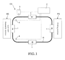
- the automated guided vehicle 1 travels along a travel route R of an orbiting track set to pass through a picking station PS where components are stored and an assembly station BS of a production line. Since the automated guided vehicle 1 travels by detecting the travel route R using a tracking sensor mounted on a vehicle, an unmanned travel can be performed.
- the automated guided vehicle 1 In the picking station PS, components necessary in the assembly station BS are loaded on the automated guided vehicle 1.
- the automated guided vehicle 1 travels along the travel route R to deliver the loaded components to the assembly station BS.
- the assembly station BS In the assembly station BS, the components loaded on the automated guided vehicle 1 are unloaded.
- the automated guided vehicle 1 returns to the picking station PS by traveling along the travel route R again. In this manner, the automated guided vehicle 1 circulates between the picking station PS and the assembly station BS.
- a charging station CS is arranged outside the travel route R of the orbiting track between the picking station PS and the assembly station BS.
- the charging station CS comprises an equipment-side control device 2 and an automatic charger 3 controlled by the equipment-side control device 2.
- a terrestrial station 4 that transmits or receives signals between the automated guided vehicle 1 and the equipment-side control device 2 is provided in inlet and outlet positions of the assembly station BS inside the travel route R.
- the automated guided vehicle 1 comprises a vehicle body 6, caster wheels 9 arranged under four corners of the vehicle body 6, a pair of spindles 7 vertically extending toward a floor surface from front and rear lower sides of the vehicle body 6, a driving unit 8 provided in the spindle 7 so as to be pivoted, a driving wheel 10 arranged to adjoin the driving unit 8, and a controller (not illustrated) that controls the driving unit 8.
- the caster wheel 9 is a traveling wheel for supporting a weight of the vehicle and is configured to pivot to follow a movement direction of the vehicle.
- the driving unit 8 is provided to rotate around a shaft of the spindle 7, and driving wheels 10 are arranged in both left and right sides of the driving unit 8.
- a pair of driving wheels 10 are arranged for a single driving unit 8.
- the driving wheels 10 are independently driven by a pair of driving motors embedded in the driving unit 8. It is noted that brackets are provided in front and rear sides of the driving unit 8, and tracking sensors (not illustrated) for detecting a travel route R are installed in the brackets.
- a battery B as a power supply for driving the driving motor of the driving unit 8 is mounted on a center position of the vehicle body 6 while it is housed in a battery casing BC of the battery unit 5.
- a battery casing BC houses the battery B as a lithium ion secondary battery and electric components such as a power relay for supplying electric power of the battery B to the driving motors of each driving unit 8.
- the battery casing BC also houses a charge and discharge monitor 11 for monitoring a condition of the battery B, a control panel 11A of the charge and discharge monitor 11 (refer to FIG. 7 ), a communication means 14 for transmitting or receiving signals to/from the automatic charger 3 or the terrestrial station 4 of the equipment-side control device 2, and the like.
- the battery B is composed of three battery modules BM, and the battery modules BM are connected in series through a busbar BB.
- the number of battery modules BM is not limited to three, but may be set arbitrarily as necessary.
- the battery module BM is formed by connecting a plurality of unit cells in series. According to this embodiment, the battery B consists of three battery modules BM, and an output voltage of the battery B in a full charging state reaches approximately 25 V.
- a receiving contactor 13 is provided in an end portion of a feed line 12 of the battery B.
- the receiving contactor 13 is installed on a casing wall surface of the battery casing BC so as to be exposed to the outside.
- the battery B is charged by connecting a feeding contactor 23 of the automatic charger 3 of the charging station CS to the receiving contactor 13. It is noted that the feeding contactor 23 is formed in an expandable/contractible manner with respect to the automatic charger 3.
- the charge and discharge monitor 11 monitors and stores various battery condition information, such as a charging capacity (battery voltage) of the battery B, a charging capacity (cell voltage) of each unit cell, a charging capacity of each battery module BM, an input/output current amount of the battery B, and a history of failure in the battery B, at a predetermined time interval (for example, 10 msec) and displays the battery condition information.
- the charge and discharge monitor 11 transmits the battery condition information to the equipment-side control device 2 or the automatic charger 3 via a communication means 14 provided on a casing wall surface of the battery casing BC so as to be exposed to the outside.
- the communication means 14 of the battery unit 5, the communication means 24 of the automatic charger 3, and the terrestrial station 4 of the equipment-side control device 2 transmit/receive information based on a communication method such as optical communication.
- a shutdown threshold value for example, 2.8 to 3 V
- the charge and discharge monitor 11 displays that the battery B has an abnormal state and abnormally stops the automated guided vehicle 1.
- the shutdown threshold value is a threshold value that changes depending on a travel condition of the automated guided vehicle 1 and the like, and is typically set to 3.0 V. However, when the automated guided vehicle 1 passes through the assembly station BS of the travel route R, the shutdown threshold value is set to a setting value lower than 3.0 V, for example, 2.8 V.
- the charge and discharge monitor 11 changes the shutdown threshold value from 3.0 V to 2.8 V when a shut-down prohibition command transmitted from the terrestrial station 4 installed in the inlet position of the assembly station BS is received by the communication means 14.
- the charge and discharge monitor 11 changes the shutdown threshold value from 2.8 V to 3.0 V when a shut-down prohibition release command transmitted from the terrestrial station 4 installed in the outlet position of the assembly station BS is received by the communication means 14. In this manner, by changing the shutdown threshold value, it is possible to suppress frequency of the abnormal stop of the automated guided vehicle 1 within the area of the assembly station BS.
- the automatic charger 3 comprises a DC power supply 21 capable of boosting a voltage to an upper limit voltage of the battery B (for example, 25.02V), a charging control device 20 that controls a charged current value and a charged voltage value supplied from the DC power supply 21 to the battery B, and a communication means 24 capable of performing communication with the communication means 14 of the automated guided vehicle 1.
- the communication means 24 exchanges various battery condition information with the communication means 14 of the automated guided vehicle 1.
- Whether or not the charging is performed is determined based on the voltage of the battery B of the automated guided vehicle 1. More specifically, the charging station CS determines whether or not the current voltage of the battery B needs to be charged, that is, whether or not the battery voltage is lower than a charging needlessness threshold voltage. If it is determined that the charging is necessary, the battery B of the automated guided vehicle 1 is charged by the automatic charger 3.
- the charging needlessness threshold voltage is set to voltage between an overcharge voltage and an overdischarge voltage of the battery B, for example, 24.9 V. It is determined that the battery B needs to be charged when the battery voltage of the battery B is lower than the charging needlessness threshold voltage set in this manner. It is determined that the battery B does not need to be charged when the battery voltage is higher than the charging needlessness threshold voltage. It is noted that by sufficiently increasing a voltage difference between the overdischarge voltage and the charging needlessness threshold voltage, it is possible to prevent overdischarging of the battery B and protect the battery B.
- the charging control device 20 is configured to be able to execute both a normal constant-current/constant-voltage charging mode and a fast constant-current/ constant-voltage charging mode in which a larger charging current than that of the normal charging mode flows to the battery B.
- the fast charging mode is suitable for a battery charging operation of the automated guided vehicle 1 necessary to be charged within a short time. According to this embodiment, the charging control device 20 executes the fast charging mode.
- the charging control device 20 may also stop the charging operation before the battery B is fully charged. For example, the charging control device 20 performs a partial charging mode in which the charging of the battery B stops when the battery voltage of the automated guided vehicle 1 rises to the charging needlessness threshold voltage. In addition, the charging control device 20 performs a partial charging mode in which the constant-current/constant-voltage charging mode is performed only for a predetermined time period, and the charging operation to the battery B stops when the predetermined time period elapses.
- dew condensation may occur on an inner surface of the battery casing BC depending on a weather condition such as humidity and temperature inside the battery casing BC. If a droplet of dew flows down along the inner surface of the battery casing BC and is attached onto the battery B or electric components, an electric failure may occur.
- the battery unit 5 of the automated guided vehicle 1 is configured to avoid attachment of a droplet of dew inside the battery casing BC from being attached onto the battery B, electric components, and the like.
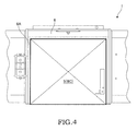
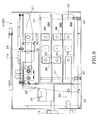
- FIG. 4 is a plan view illustrating appearance of the battery unit 5 mounted on the vehicle body 6 of the automated guided vehicle 1.
- a mount space 6A partitioned by a vehicle body frame extending along a front-rear direction of the vehicle is formed in the center position of the vehicle body 6 of the automated guided vehicle 1.
- the battery unit 5 is housed in this mount space 6A.
- the battery unit 5 is fixed to the mount space 6A using a fixing means (not illustrated).
- the battery unit 5 has the battery casing BC, and the battery casing BC is formed in a box shape by the casing walls.
- the casing wall of the battery casing BC in the right side of the vehicle (casing side wall surface), facing the automatic charger 3 during the charging operation, is exposed to the outside from the mount space 6A of the vehicle body 6 as illustrated in FIG. 5 .
- the receiving contactor 13, the communication means 14, and the display unit 15 for displaying a condition of the battery B are arranged on the casing side wall surface of the battery casing BC in an exposed state.
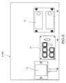
- a vertical wall bracket 25 as a vertical wall for partitioning an inner space is provided inside the battery casing BC.
- the vertical wall bracket 25 is a wall member fixed to the bottom surface of the battery casing BC to be erected in a perpendicular direction, and extends along a front-rear direction of the vehicle.
- the battery modules BM of the battery B are vertically arranged side by side in an area inside the battery casing BC far from the vertical wall bracket 25 (an area farther from the casing side wall surface out of the areas partitioned by the vertical wall bracket 25).
- electric components such as the receiving contactor 13, the communication means 14, the display unit 15, and the power relay 26 are arranged in an area inside the battery casing BC in a near side from the vertical wall bracket 25 (an area close to the casing side wall surface out of the areas partitioned by the vertical wall bracket 25) in a position distant from the bottom surface of the battery casing BC.
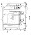
- a pair of horizontal beam brackets 27 are provided over the vertical wall bracket 25.
- a pair of horizontal beam brackets 27 are arranged in parallel to each other with a predetermined distance in a front-rear direction of the vehicle.
- a base end portion of the horizontal beam bracket 27 is fixed to an upper portion of the vertical wall bracket 25, and a leading end of the horizontal beam bracket 27 extends to a farther side of the battery casing BC.
- a single support plate 28 is provided on upper surfaces of the pair of horizontal beam brackets 27.
- a control panel 11A and the like included in the charge and discharge monitor 11 are placed on the upper surface of the support plate 28. It is noted that the battery modules BM are arranged under the horizontal beam bracket 27, and the support plate 28 is configured to cover the upper side of the battery B.
- Three battery modules BM are vertically stacked. Spacers 29 are interposed between the front side ends and the rear side ends of the vertically neighboring battery modules BM. Since each battery module BM is stacked by interposing the spacer 29, a gap is formed between the neighboring battery modules BM. Due to this gap, thermal expansion of a stacking direction caused by a temperature increase generated by charging or discharging the battery modules BM is allowed. In addition, since the air flows through the gap between the battery modules BM, it is possible to promote dissipation of the heat caused by a temperature increase of the battery modules BM.
- a collar sleeve 30 is arranged between a lower surface (bottom surface) of the lowermost battery module BM and the bottom surface of the battery casing BC, so that the lower surface of the lowermost battery module BM is arranged to float over the bottom surface of the battery casing BC.
- the three battery modules BM have vertically penetrating fixing holes 32, so that the battery modules BM and the battery casing BC are fixed using fixing bolts 31 penetrating the collar sleeve 30 and the fixing holes 32 of each battery module BM.
- the stacked battery modules BM are electrically connected to a busbar BB, and the busbar BB connected to output terminals of the uppermost and lowermost battery modules BM is connected to the receiving contactor 13. It is noted that the busbar BB used to connect the output terminals of the uppermost and lowermost battery modules BM and the receiving contactor 13 is configured to feed electric power to the driving unit 8 through the power relay 26 although a part thereof is not illustrated.
- dew condensation may occur on the inner surface of the battery casing BC depending on an ambient temperature change of the battery casing BC or a condition such as humidity inside the battery casing BC.
- the lowermost battery module BM of the battery casing BC is arranged to float over the casing bottom surface using the collar sleeve 30. For this reason, even when droplets of dew generated on the inner surface of the battery casing BC are accumulated on the casing bottom surface along the inner surface of the battery casing BC, it is possible to prevent droplets of dew from being attached onto the battery module BM. In addition, it is possible to dry droplets of dew accumulated on the casing bottom surface using the heat generated from the battery module BM.
- electric components such as the power relay 26, the communication means 14, and the display unit 15 or the control panel 11A are also arranged in a position separated from the bottom surface of the battery casing BC. Therefore, it is possible to prevent droplets of dew from being attached onto such electric components and the like.
- the battery module BM constituting battery B is arranged in a space defined by the vertical wall bracket 25, the horizontal beam bracket 27, and the support plate 28. For this reason, even when an impact is applied from the outside, particularly, from the lateral surface side of the battery unit 5, it is possible to prevent the electric components such as the power relay 26, the communication means 14, and the display unit 15 arranged in the vertical wall bracket 25 and the control panel 11A arranged in the support plate 28 from making contact with the battery modules BM. In this manner, it is possible to protect the battery modules BM using the vertical wall bracket 25, the horizontal beam bracket 27, and the support plate 28 and prevent a damage in the battery modules BM.
- the vertical wall bracket 25, the horizontal beam bracket 27, and the support plate 28 serve as a partitioning wall for partitioning a space for the battery modules BM and a space for the electric components such as the power relay 26 and the control panel 11A. Therefore, it is possible to prevent a temperature change of the battery modules BM from affecting the electric components or the control panel 11A.
- the battery unit 5 of the automated guided vehicle 1 comprises the battery B, the control panel 11A of the charge and discharge monitor 11 for monitoring a charge and discharge condition of the battery B, the electric components such as the power relay 26 electrically connected to the battery B, and the battery casing BC for housing these components.
- the battery B is arranged inside the battery casing BC such that its bottom surface is separated from the bottom surface of the battery casing BC. As a result, even when droplets of dew generated inside the battery casing BC are accumulated on the casing bottom surface, it is possible to prevent the droplets of dew from being attached onto the battery B and the like. In addition, using the heat generated from the battery B, it is possible to dry the droplets of dew accumulated on the casing bottom surface.
- the battery B is configured by stacking a plurality of battery modules BM, and the spacer 29 is interposed to form a gap between the vertically neighboring battery modules BM.
- thermal expansion in a stacking direction caused by a temperature increase generated by the charging or discharging operation of the battery modules BM is allowed.
- the air flows through the gap between battery modules BM it is possible to promote dissipation of the heat caused by a temperature increase of the battery modules BM.
- the casing wall surface (lateral wall surface) of the battery casing BC in the lateral side of the automated guided vehicle 1 is exposed to the outside from the mount space 6A of the vehicle body 6, and the vertical wall bracket 25 erected from the casing bottom surface is provided to face the lateral side wall inside the battery casing BC.
- the battery B is arranged in a far side of the battery casing BC from the vertical wall bracket 25, and the electric components are arranged in a near side from the vertical wall bracket 25. For this reason, even when an impact is applied from the lateral wall surface of the battery casing BC exposed to the outside, it is possible to prevent the electric components such as the power relay 26 arranged in the vertical wall bracket 25 from making contact with the battery modules BM. For this reason, it is possible to prevent a damage in the battery modules BM and protect the battery modules BM. Furthermore, it is possible to prevent a temperature change of the battery modules BM from affecting the electric components and the control panel 11A.
- the horizontal beam bracket 27 is provided over the vertical wall bracket 25, and the support plate 28 that covers an upper side of the battery B is arranged in the horizontal beam bracket 27.
- the control panel 11A of the charge and discharge monitor 11 is placed on the upper surface of the support plate 28. For this reason, even when an impact is applied from the lateral wall surface of the battery casing BC exposed to the outside, it is possible to prevent the control panel 11A arranged on the support plate 28 from making contact with the battery module BM. Accordingly, it is possible to prevent a damage in the battery modules BM and protect the battery modules BM. In addition, it is possible to prevent a temperature change of the battery modules BM from affecting the control panel 11A.
- the charge and discharge monitor 11 monitors a voltage of the battery modules BM of the battery B. When a voltage of any one of the battery modules BM becomes equal to or lower than a predetermined setting voltage, the charge and discharge monitor 11 displays the abnormal state of the battery B and abnormally stops the automated guided vehicle 1. When the automated guided vehicle 1 travels within the area of the assembly station BS, the setting voltage value is lowered, compared to a case where it travels other areas. For this reason, while the automated guided vehicle 1 travels within the area of the assembly station BS, it is possible to suppress frequency of the abnormal stop of the automated guided vehicle 1.
Landscapes
- Engineering & Computer Science (AREA)
- Chemical & Material Sciences (AREA)
- Chemical Kinetics & Catalysis (AREA)
- Electrochemistry (AREA)
- General Chemical & Material Sciences (AREA)
- Manufacturing & Machinery (AREA)
- Mechanical Engineering (AREA)
- Transportation (AREA)
- Power Engineering (AREA)
- Microelectronics & Electronic Packaging (AREA)
- Sustainable Energy (AREA)
- Sustainable Development (AREA)
- Life Sciences & Earth Sciences (AREA)
- Aviation & Aerospace Engineering (AREA)
- Materials Engineering (AREA)
- Electric Propulsion And Braking For Vehicles (AREA)
- Charge And Discharge Circuits For Batteries Or The Like (AREA)
- Secondary Cells (AREA)
- Arrangement Or Mounting Of Propulsion Units For Vehicles (AREA)
- Battery Mounting, Suspending (AREA)
Description
- This invention relates to a battery unit of an automated guided vehicle that uses a battery as a power supply.
- In general, a lead storage battery is employed as a driving source of a motor in an automated guided vehicle used in a factory or a depot. In the technique discussed in
JP 1991-37967 A JP 2007-74800 A - In the automated guided vehicle discussed in
JP 2007-74800 A - In an automated guided vehicle that uses a lithium ion battery as a battery, a battery unit is configured by integrating and housing a battery, a control panel such as a charge and discharge monitor that monitors a charge and discharge condition of the battery, and other electric components in a battery casing. In such a battery unit, dew condensation may occur on an inner surface of the battery casing depending on a weather condition such as humidity or temperature inside the battery casing. An electric failure may occur if a droplet of dew flows down along the inner surface of the battery casing and is attached on the battery, the electric component, and the like.
- This invention provides a battery unit of an automated guided vehicle capable of avoiding droplets of dew inside the battery casing from being attached onto the battery or the electric components.
- According to an aspect of this invention, there is provided a battery unit of an automated guided vehicle comprising a casing installed in the automated guided vehicle body, a battery housed in the casing, a control panel included in a charge and discharge monitor housed in the casing to monitor a charge and discharge state of the battery, and electric components housed in the casing and electrically connected to the battery. The battery is arranged in the casing such that the battery bottom surface is separated from the casing bottom surface.
-
-
FIG. 1 is a diagram illustrating a traveling route of an automated guided vehicle according to an embodiment of this disclosure. -
FIG. 2 is a schematic diagram illustrating the automated guided vehicle according to this embodiment. -
FIG. 3 is a diagram illustrating connection between a battery unit of the automated guided vehicle and a charging station during a charging operation. -
FIG. 4 is a plan view illustrating a battery unit mounted on the automated guided vehicle. -
FIG. 5 is a side view illustrating the battery unit. -
FIG. 6 is a plan view illustrating the battery unit. -
FIG. 7 is a cross-sectional view taken along a line VII-VII ofFIG. 6 . -
FIG. 8 is a cross-sectional view taken along a line VIII-VIII ofFIG. 6 . - Hereinafter, a battery unit of an automated guided vehicle according to this embodiment will be described with reference to the accompanying drawings.
- Referring to
FIG. 1 , the automated guidedvehicle 1 travels along a travel route R of an orbiting track set to pass through a picking station PS where components are stored and an assembly station BS of a production line. Since the automated guidedvehicle 1 travels by detecting the travel route R using a tracking sensor mounted on a vehicle, an unmanned travel can be performed. - In the picking station PS, components necessary in the assembly station BS are loaded on the automated guided
vehicle 1. The automated guidedvehicle 1 travels along the travel route R to deliver the loaded components to the assembly station BS. In the assembly station BS, the components loaded on the automated guidedvehicle 1 are unloaded. Then, the automated guidedvehicle 1 returns to the picking station PS by traveling along the travel route R again. In this manner, the automated guidedvehicle 1 circulates between the picking station PS and the assembly station BS. A charging station CS is arranged outside the travel route R of the orbiting track between the picking station PS and the assembly station BS. - The charging station CS comprises an equipment-
side control device 2 and anautomatic charger 3 controlled by the equipment-side control device 2. In addition, a terrestrial station 4 that transmits or receives signals between the automated guidedvehicle 1 and the equipment-side control device 2 is provided in inlet and outlet positions of the assembly station BS inside the travel route R. - Referring to
FIG. 2 , the automated guidedvehicle 1 comprises avehicle body 6,caster wheels 9 arranged under four corners of thevehicle body 6, a pair ofspindles 7 vertically extending toward a floor surface from front and rear lower sides of thevehicle body 6, adriving unit 8 provided in thespindle 7 so as to be pivoted, adriving wheel 10 arranged to adjoin thedriving unit 8, and a controller (not illustrated) that controls thedriving unit 8. - The
caster wheel 9 is a traveling wheel for supporting a weight of the vehicle and is configured to pivot to follow a movement direction of the vehicle. Thedriving unit 8 is provided to rotate around a shaft of thespindle 7, and drivingwheels 10 are arranged in both left and right sides of thedriving unit 8. A pair ofdriving wheels 10 are arranged for asingle driving unit 8. Thedriving wheels 10 are independently driven by a pair of driving motors embedded in thedriving unit 8. It is noted that brackets are provided in front and rear sides of thedriving unit 8, and tracking sensors (not illustrated) for detecting a travel route R are installed in the brackets. - A battery B as a power supply for driving the driving motor of the
driving unit 8 is mounted on a center position of thevehicle body 6 while it is housed in a battery casing BC of thebattery unit 5. - Referring to
FIG. 3 , a battery casing BC houses the battery B as a lithium ion secondary battery and electric components such as a power relay for supplying electric power of the battery B to the driving motors of eachdriving unit 8. In addition, the battery casing BC also houses a charge anddischarge monitor 11 for monitoring a condition of the battery B, acontrol panel 11A of the charge and discharge monitor 11 (refer toFIG. 7 ), a communication means 14 for transmitting or receiving signals to/from theautomatic charger 3 or the terrestrial station 4 of the equipment-side control device 2, and the like. - The battery B is composed of three battery modules BM, and the battery modules BM are connected in series through a busbar BB. The number of battery modules BM is not limited to three, but may be set arbitrarily as necessary. The battery module BM is formed by connecting a plurality of unit cells in series. According to this embodiment, the battery B consists of three battery modules BM, and an output voltage of the battery B in a full charging state reaches approximately 25 V.
- A
receiving contactor 13 is provided in an end portion of afeed line 12 of the battery B. Thereceiving contactor 13 is installed on a casing wall surface of the battery casing BC so as to be exposed to the outside. The battery B is charged by connecting afeeding contactor 23 of theautomatic charger 3 of the charging station CS to thereceiving contactor 13. It is noted that thefeeding contactor 23 is formed in an expandable/contractible manner with respect to theautomatic charger 3. - The charge and
discharge monitor 11 monitors and stores various battery condition information, such as a charging capacity (battery voltage) of the battery B, a charging capacity (cell voltage) of each unit cell, a charging capacity of each battery module BM, an input/output current amount of the battery B, and a history of failure in the battery B, at a predetermined time interval (for example, 10 msec) and displays the battery condition information. The charge anddischarge monitor 11 transmits the battery condition information to the equipment-side control device 2 or theautomatic charger 3 via a communication means 14 provided on a casing wall surface of the battery casing BC so as to be exposed to the outside. The communication means 14 of thebattery unit 5, the communication means 24 of theautomatic charger 3, and the terrestrial station 4 of the equipment-side control device 2 transmit/receive information based on a communication method such as optical communication. - If the charging capacity (voltage) of each battery module BM of the battery B becomes equal to or lower than a shutdown threshold value (for example, 2.8 to 3 V), so that an overdischarge state is determined, the charge and
discharge monitor 11 displays that the battery B has an abnormal state and abnormally stops the automated guidedvehicle 1. The shutdown threshold value is a threshold value that changes depending on a travel condition of the automated guidedvehicle 1 and the like, and is typically set to 3.0 V. However, when the automated guidedvehicle 1 passes through the assembly station BS of the travel route R, the shutdown threshold value is set to a setting value lower than 3.0 V, for example, 2.8 V. - That is, the charge and
discharge monitor 11 changes the shutdown threshold value from 3.0 V to 2.8 V when a shut-down prohibition command transmitted from the terrestrial station 4 installed in the inlet position of the assembly station BS is received by the communication means 14. In addition, the charge anddischarge monitor 11 changes the shutdown threshold value from 2.8 V to 3.0 V when a shut-down prohibition release command transmitted from the terrestrial station 4 installed in the outlet position of the assembly station BS is received by the communication means 14. In this manner, by changing the shutdown threshold value, it is possible to suppress frequency of the abnormal stop of the automated guidedvehicle 1 within the area of the assembly station BS. - Since the automated guided
vehicle 1 travels using electric power of the battery B, the charging capacity (battery voltage) of the battery B is lowered as much as the automated guidedvehicle 1 travels. For this reason, the battery B is charged using theautomatic charger 3 by temporarily parking the automated guidedvehicle 1 in the charging station CS. As illustrated inFIG. 3 , theautomatic charger 3 comprises aDC power supply 21 capable of boosting a voltage to an upper limit voltage of the battery B (for example, 25.02V), a chargingcontrol device 20 that controls a charged current value and a charged voltage value supplied from theDC power supply 21 to the battery B, and a communication means 24 capable of performing communication with the communication means 14 of the automated guidedvehicle 1. The communication means 24 exchanges various battery condition information with the communication means 14 of the automated guidedvehicle 1. - Whether or not the charging is performed is determined based on the voltage of the battery B of the automated guided
vehicle 1. More specifically, the charging station CS determines whether or not the current voltage of the battery B needs to be charged, that is, whether or not the battery voltage is lower than a charging needlessness threshold voltage. If it is determined that the charging is necessary, the battery B of the automated guidedvehicle 1 is charged by theautomatic charger 3. - The charging needlessness threshold voltage is set to voltage between an overcharge voltage and an overdischarge voltage of the battery B, for example, 24.9 V. It is determined that the battery B needs to be charged when the battery voltage of the battery B is lower than the charging needlessness threshold voltage set in this manner. It is determined that the battery B does not need to be charged when the battery voltage is higher than the charging needlessness threshold voltage. It is noted that by sufficiently increasing a voltage difference between the overdischarge voltage and the charging needlessness threshold voltage, it is possible to prevent overdischarging of the battery B and protect the battery B.
- When the battery B is charged, the feeding
contactor 23 and the receivingcontactor 13 are connected to each other by extending the feedingcontactor 23 of theautomatic charger 3 toward the receivingcontactor 13 of the automated guidedvehicle 1. In this manner, by connecting the feedingcontactor 23 and the receivingcontactor 13, the charging electric power is supplied to the battery B from theDC power supply 21 of theautomatic charger 3. The chargingcontrol device 20 is configured to be able to execute both a normal constant-current/constant-voltage charging mode and a fast constant-current/ constant-voltage charging mode in which a larger charging current than that of the normal charging mode flows to the battery B. The fast charging mode is suitable for a battery charging operation of the automated guidedvehicle 1 necessary to be charged within a short time. According to this embodiment, the chargingcontrol device 20 executes the fast charging mode. - The charging
control device 20 may also stop the charging operation before the battery B is fully charged. For example, the chargingcontrol device 20 performs a partial charging mode in which the charging of the battery B stops when the battery voltage of the automated guidedvehicle 1 rises to the charging needlessness threshold voltage. In addition, the chargingcontrol device 20 performs a partial charging mode in which the constant-current/constant-voltage charging mode is performed only for a predetermined time period, and the charging operation to the battery B stops when the predetermined time period elapses. - In the
battery unit 5 mounted on the automated guidedvehicle 1, dew condensation may occur on an inner surface of the battery casing BC depending on a weather condition such as humidity and temperature inside the battery casing BC. If a droplet of dew flows down along the inner surface of the battery casing BC and is attached onto the battery B or electric components, an electric failure may occur. - For this reason, the
battery unit 5 of the automated guidedvehicle 1 according to this embodiment is configured to avoid attachment of a droplet of dew inside the battery casing BC from being attached onto the battery B, electric components, and the like. -
FIG. 4 is a plan view illustrating appearance of thebattery unit 5 mounted on thevehicle body 6 of the automated guidedvehicle 1. - Referring to
FIG. 4 , amount space 6A partitioned by a vehicle body frame extending along a front-rear direction of the vehicle is formed in the center position of thevehicle body 6 of the automated guidedvehicle 1. Thebattery unit 5 is housed in thismount space 6A. Thebattery unit 5 is fixed to themount space 6A using a fixing means (not illustrated). Thebattery unit 5 has the battery casing BC, and the battery casing BC is formed in a box shape by the casing walls. - It is noted that the casing wall of the battery casing BC in the right side of the vehicle (casing side wall surface), facing the
automatic charger 3 during the charging operation, is exposed to the outside from themount space 6A of thevehicle body 6 as illustrated inFIG. 5 . The receivingcontactor 13, the communication means 14, and thedisplay unit 15 for displaying a condition of the battery B are arranged on the casing side wall surface of the battery casing BC in an exposed state. - Referring to
FIGs. 6 and7 , avertical wall bracket 25 as a vertical wall for partitioning an inner space is provided inside the battery casing BC. Thevertical wall bracket 25 is a wall member fixed to the bottom surface of the battery casing BC to be erected in a perpendicular direction, and extends along a front-rear direction of the vehicle. The battery modules BM of the battery B are vertically arranged side by side in an area inside the battery casing BC far from the vertical wall bracket 25 (an area farther from the casing side wall surface out of the areas partitioned by the vertical wall bracket 25). Meanwhile, electric components such as the receivingcontactor 13, the communication means 14, thedisplay unit 15, and thepower relay 26 are arranged in an area inside the battery casing BC in a near side from the vertical wall bracket 25 (an area close to the casing side wall surface out of the areas partitioned by the vertical wall bracket 25) in a position distant from the bottom surface of the battery casing BC. - Referring to
FIGs. 7 and8 , a pair ofhorizontal beam brackets 27 are provided over thevertical wall bracket 25. A pair ofhorizontal beam brackets 27 are arranged in parallel to each other with a predetermined distance in a front-rear direction of the vehicle. A base end portion of thehorizontal beam bracket 27 is fixed to an upper portion of thevertical wall bracket 25, and a leading end of thehorizontal beam bracket 27 extends to a farther side of the battery casing BC. Asingle support plate 28 is provided on upper surfaces of the pair ofhorizontal beam brackets 27. Acontrol panel 11A and the like included in the charge and discharge monitor 11 are placed on the upper surface of thesupport plate 28. It is noted that the battery modules BM are arranged under thehorizontal beam bracket 27, and thesupport plate 28 is configured to cover the upper side of the battery B. - Three battery modules BM are vertically stacked.
Spacers 29 are interposed between the front side ends and the rear side ends of the vertically neighboring battery modules BM. Since each battery module BM is stacked by interposing thespacer 29, a gap is formed between the neighboring battery modules BM. Due to this gap, thermal expansion of a stacking direction caused by a temperature increase generated by charging or discharging the battery modules BM is allowed. In addition, since the air flows through the gap between the battery modules BM, it is possible to promote dissipation of the heat caused by a temperature increase of the battery modules BM. - A
collar sleeve 30 is arranged between a lower surface (bottom surface) of the lowermost battery module BM and the bottom surface of the battery casing BC, so that the lower surface of the lowermost battery module BM is arranged to float over the bottom surface of the battery casing BC. The three battery modules BM have vertically penetrating fixingholes 32, so that the battery modules BM and the battery casing BC are fixed using fixingbolts 31 penetrating thecollar sleeve 30 and the fixing holes 32 of each battery module BM. - Referring to
FIG. 8 , the stacked battery modules BM are electrically connected to a busbar BB, and the busbar BB connected to output terminals of the uppermost and lowermost battery modules BM is connected to the receivingcontactor 13. It is noted that the busbar BB used to connect the output terminals of the uppermost and lowermost battery modules BM and the receivingcontactor 13 is configured to feed electric power to thedriving unit 8 through thepower relay 26 although a part thereof is not illustrated. - In the
battery unit 5 of the automated guidedvehicle 1 described above, dew condensation may occur on the inner surface of the battery casing BC depending on an ambient temperature change of the battery casing BC or a condition such as humidity inside the battery casing BC. In this regard, in thebattery unit 5, the lowermost battery module BM of the battery casing BC is arranged to float over the casing bottom surface using thecollar sleeve 30. For this reason, even when droplets of dew generated on the inner surface of the battery casing BC are accumulated on the casing bottom surface along the inner surface of the battery casing BC, it is possible to prevent droplets of dew from being attached onto the battery module BM. In addition, it is possible to dry droplets of dew accumulated on the casing bottom surface using the heat generated from the battery module BM. - In the
battery unit 5 of the automated guidedvehicle 1, electric components such as thepower relay 26, the communication means 14, and thedisplay unit 15 or thecontrol panel 11A are also arranged in a position separated from the bottom surface of the battery casing BC. Therefore, it is possible to prevent droplets of dew from being attached onto such electric components and the like. - In the
battery unit 5 of the automated guidedvehicle 1, the battery module BM constituting battery B is arranged in a space defined by thevertical wall bracket 25, thehorizontal beam bracket 27, and thesupport plate 28. For this reason, even when an impact is applied from the outside, particularly, from the lateral surface side of thebattery unit 5, it is possible to prevent the electric components such as thepower relay 26, the communication means 14, and thedisplay unit 15 arranged in thevertical wall bracket 25 and thecontrol panel 11A arranged in thesupport plate 28 from making contact with the battery modules BM. In this manner, it is possible to protect the battery modules BM using thevertical wall bracket 25, thehorizontal beam bracket 27, and thesupport plate 28 and prevent a damage in the battery modules BM. - In
battery unit 5 of the automated guidedvehicle 1, thevertical wall bracket 25, thehorizontal beam bracket 27, and thesupport plate 28 serve as a partitioning wall for partitioning a space for the battery modules BM and a space for the electric components such as thepower relay 26 and thecontrol panel 11A. Therefore, it is possible to prevent a temperature change of the battery modules BM from affecting the electric components or thecontrol panel 11A. - The following effects can be obtained using the
battery unit 5 of the automated guidedvehicle 1 according to this embodiment described above. - (I) The
battery unit 5 of the automated guidedvehicle 1 comprises the battery B, thecontrol panel 11A of the charge and discharge monitor 11 for monitoring a charge and discharge condition of the battery B, the electric components such as thepower relay 26 electrically connected to the battery B, and the battery casing BC for housing these components. The battery B is arranged inside the battery casing BC such that its bottom surface is separated from the bottom surface of the battery casing BC. As a result, even when droplets of dew generated inside the battery casing BC are accumulated on the casing bottom surface, it is possible to prevent the droplets of dew from being attached onto the battery B and the like. In addition, using the heat generated from the battery B, it is possible to dry the droplets of dew accumulated on the casing bottom surface. - (II) The battery B is configured by stacking a plurality of battery modules BM, and the
spacer 29 is interposed to form a gap between the vertically neighboring battery modules BM. As a result, thermal expansion in a stacking direction caused by a temperature increase generated by the charging or discharging operation of the battery modules BM is allowed. In addition, since the air flows through the gap between battery modules BM, it is possible to promote dissipation of the heat caused by a temperature increase of the battery modules BM. - (III) The casing wall surface (lateral wall surface) of the battery casing BC in the lateral side of the automated guided
vehicle 1 is exposed to the outside from themount space 6A of thevehicle body 6, and thevertical wall bracket 25 erected from the casing bottom surface is provided to face the lateral side wall inside the battery casing BC. The battery B is arranged in a far side of the battery casing BC from thevertical wall bracket 25, and the electric components are arranged in a near side from thevertical wall bracket 25. For this reason, even when an impact is applied from the lateral wall surface of the battery casing BC exposed to the outside, it is possible to prevent the electric components such as thepower relay 26 arranged in thevertical wall bracket 25 from making contact with the battery modules BM. For this reason, it is possible to prevent a damage in the battery modules BM and protect the battery modules BM. Furthermore, it is possible to prevent a temperature change of the battery modules BM from affecting the electric components and thecontrol panel 11A. - (IV) The
horizontal beam bracket 27 is provided over thevertical wall bracket 25, and thesupport plate 28 that covers an upper side of the battery B is arranged in thehorizontal beam bracket 27. Thecontrol panel 11A of the charge and discharge monitor 11 is placed on the upper surface of thesupport plate 28. For this reason, even when an impact is applied from the lateral wall surface of the battery casing BC exposed to the outside, it is possible to prevent thecontrol panel 11A arranged on thesupport plate 28 from making contact with the battery module BM. Accordingly, it is possible to prevent a damage in the battery modules BM and protect the battery modules BM. In addition, it is possible to prevent a temperature change of the battery modules BM from affecting thecontrol panel 11A. - (V) The charge and discharge monitor 11 monitors a voltage of the battery modules BM of the battery B. When a voltage of any one of the battery modules BM becomes equal to or lower than a predetermined setting voltage, the charge and discharge monitor 11 displays the abnormal state of the battery B and abnormally stops the automated guided
vehicle 1. When the automated guidedvehicle 1 travels within the area of the assembly station BS, the setting voltage value is lowered, compared to a case where it travels other areas. For this reason, while the automated guidedvehicle 1 travels within the area of the assembly station BS, it is possible to suppress frequency of the abnormal stop of the automated guidedvehicle 1. - Although embodiments of this invention have been described hereinbefore, the aforementioned embodiments are just a part of applications of this invention, and are not intended to limit the technical scope of this invention to specific configurations of the aforementioned embodiments.
- This application is based on and claims priority to Japanese Patent Application No.
2012-171715
Claims (5)
- A battery unit of an automated guided vehicle, comprising a casing installed in a vehicle body of the automated guided vehicle,
a battery housed in the casing,
a control panel housed in the casing and included in a charge and discharge monitor to monitor a charge and discharge state of the battery, and
electric components housed in the casing and electrically connected to the battery,
wherein the battery is arranged in the casing such that a battery bottom surface is separated from a casing bottom surface. - The battery unit of the automated guided vehicle according to claim 1, wherein the battery is configured by stacking a plurality of battery modules are comprised of a lithium ion battery, and a spacer is interposed such that a gap is formed between the neighboring battery modules.
- The battery unit of the automated guided vehicle according to claim 1 or 2, wherein the casing is arranged in the automated guided vehicle such that a casing side wall surface is exposed to the outside,
a vertical wall bracket erected from the casing bottom surface is arranged inside the casing to face the casing side wall surface,
the battery is arranged in a back side of the casing from the vertical wall bracket in a position distant from the casing side wall surface,
the electric components are arranged in a near side of the casing from the vertical wall bracket in a position close to the casing side wall surface. - The battery unit of the automated guided vehicle according to claim 3, further comprising a horizontal beam bracket fixed to an upper side of the vertical wall bracket, and
a support plate provided in the horizontal beam bracket and arranged to cover an upper side of the battery,
wherein the control panel is arranged on the upper surface of the support plate. - The battery unit of the automated guided vehicle according to any one of claims 1 to 4, further comprising a fixing hole provided in the battery to penetrate in a vertical direction,
a cylindrical sleeve arranged between a bottom surface of the battery and a bottom surface of the casing, and
a bolt used to fix the battery and the casing while the sleeve is inserted into the fixing hole.
Applications Claiming Priority (2)
| Application Number | Priority Date | Filing Date | Title |
|---|---|---|---|
| JP2012171715 | 2012-08-02 | ||
| PCT/JP2013/070739 WO2014021379A1 (en) | 2012-08-02 | 2013-07-31 | Battery unit for unpiloted conveyance vehicles |
Publications (3)
| Publication Number | Publication Date |
|---|---|
| EP2882009A1 true EP2882009A1 (en) | 2015-06-10 |
| EP2882009A4 EP2882009A4 (en) | 2015-07-15 |
| EP2882009B1 EP2882009B1 (en) | 2017-06-28 |
Family
ID=50028049
Family Applications (1)
| Application Number | Title | Priority Date | Filing Date |
|---|---|---|---|
| EP13826177.1A Active EP2882009B1 (en) | 2012-08-02 | 2013-07-31 | Battery unit for unpiloted conveyance vehicles |
Country Status (10)
| Country | Link |
|---|---|
| US (1) | US9698393B2 (en) |
| EP (1) | EP2882009B1 (en) |
| JP (1) | JP5994857B2 (en) |
| KR (1) | KR101741341B1 (en) |
| CN (1) | CN104508859B (en) |
| BR (1) | BR112015002201B1 (en) |
| MX (1) | MX338350B (en) |
| MY (1) | MY154359A (en) |
| RU (1) | RU2569935C1 (en) |
| WO (1) | WO2014021379A1 (en) |
Families Citing this family (14)
| Publication number | Priority date | Publication date | Assignee | Title |
|---|---|---|---|---|
| US10272567B2 (en) * | 2015-05-26 | 2019-04-30 | The Aes Corporation | Automated robotic battery tug |
| USD857072S1 (en) * | 2016-01-22 | 2019-08-20 | Symbotic, LLC | Automated guided vehicle |
| USD879173S1 (en) * | 2017-02-14 | 2020-03-24 | Beijing Jingdong Shangke Information Technology Co, Ltd | Shuttle vehicle |
| USD871476S1 (en) * | 2017-02-17 | 2019-12-31 | Safelog Gmbh | Automated guided vehicle |
| USD891493S1 (en) * | 2018-05-15 | 2020-07-28 | Beijing Jingdong Shangke Information Technology Co., Ltd. | Shuttle car for automatic storage system |
| US11817731B2 (en) | 2018-10-12 | 2023-11-14 | Briggs & Stratton, Llc | Battery assembly for battery powered equipment |
| US11396388B2 (en) | 2018-12-20 | 2022-07-26 | The Boeing Company | Optimized power balanced variable thrust transfer orbits to minimize an electric orbit raising duration |
| US11401053B2 (en) * | 2018-12-20 | 2022-08-02 | The Boeing Company | Autonomous control of electric power supplied to a thruster during electric orbit raising |
| US11753188B2 (en) | 2018-12-20 | 2023-09-12 | The Boeing Company | Optimized power balanced low thrust transfer orbits utilizing split thruster execution |
| CN113826271A (en) * | 2019-03-28 | 2021-12-21 | 布里格斯斯特拉顿公司 | Modular battery assembly for battery powered devices |
| RU2726164C1 (en) * | 2019-12-30 | 2020-07-09 | Акционерное общество "Энергия" | Accumulator unit |
| RU2764402C1 (en) * | 2020-10-29 | 2022-01-17 | Общество с ограниченной ответственностью «Орион» | Light unit |
| RU202293U1 (en) * | 2020-11-10 | 2021-02-10 | Сергей Андреевич Липицкий | VEHICLE BATTERY WITH DIAGNOSTIC AND RESERVE FUNCTION |
| CN117559064B (en) * | 2024-01-12 | 2024-04-26 | 长安绿电科技有限公司 | Distributed new energy automobile power battery pack |
Family Cites Families (19)
| Publication number | Priority date | Publication date | Assignee | Title |
|---|---|---|---|---|
| JPH0730413Y2 (en) | 1988-08-10 | 1995-07-12 | 株式会社豊田自動織機製作所 | Drainage structure for battery-powered industrial vehicles |
| JP2977206B2 (en) | 1989-07-04 | 1999-11-15 | 松下電器産業株式会社 | Battery for automatic guided vehicle, automatic guided vehicle using battery, automatic battery charging device for automatic guided vehicle, and automatic charging method thereof |
| RU2086052C1 (en) * | 1996-01-17 | 1997-07-27 | Акционерное общество закрытого типа "Подольский аккумуляторный завод" | Storage battery (options) |
| JP2006024445A (en) * | 2004-07-08 | 2006-01-26 | Toyota Motor Corp | Battery pack and power supply |
| KR20060091948A (en) | 2005-02-16 | 2006-08-22 | 기아자동차주식회사 | Battery tray of hybrid vehicle |
| JP4992244B2 (en) * | 2005-04-07 | 2012-08-08 | 日産自動車株式会社 | Battery module and battery pack |
| US20070017720A1 (en) * | 2005-07-25 | 2007-01-25 | Kazuhiro Fujii | Battery device of vehicle power supply |
| JP2007074800A (en) | 2005-09-06 | 2007-03-22 | Tsubakimoto Chain Co | Battery charge/discharge management system of automatic carrier vehicle |
| US8026698B2 (en) * | 2006-02-09 | 2011-09-27 | Scheucher Karl F | Scalable intelligent power supply system and method |
| JP4961876B2 (en) * | 2006-02-15 | 2012-06-27 | トヨタ自動車株式会社 | Battery cooling structure |
| JP2007287494A (en) * | 2006-04-18 | 2007-11-01 | Nippon Sharyo Seizo Kaisha Ltd | Battery device |
| JP4812529B2 (en) | 2006-06-14 | 2011-11-09 | トヨタ自動車株式会社 | Power supply device and vehicle |
| KR100863729B1 (en) | 2006-09-18 | 2008-10-16 | 주식회사 엘지화학 | Battery module interface |
| RU2425436C2 (en) * | 2006-10-13 | 2011-07-27 | Энердел, Инк. | Battery with temperature monitoring device |
| JP4882852B2 (en) * | 2007-04-26 | 2012-02-22 | トヨタ自動車株式会社 | Power supply |
| JP4306783B2 (en) | 2007-12-14 | 2009-08-05 | 三菱自動車工業株式会社 | Electric vehicle battery unit mounting structure |
| JP5212011B2 (en) | 2008-10-22 | 2013-06-19 | トヨタ車体株式会社 | Battery powered car |
| KR101065306B1 (en) * | 2009-12-22 | 2011-09-16 | 에스비리모티브 주식회사 | Battery pack |
| JP5603504B2 (en) | 2011-10-28 | 2014-10-08 | 川崎重工業株式会社 | Straddle-type electric vehicle |
-
2013
- 2013-07-31 KR KR1020157003229A patent/KR101741341B1/en active Active
- 2013-07-31 WO PCT/JP2013/070739 patent/WO2014021379A1/en not_active Ceased
- 2013-07-31 BR BR112015002201-4A patent/BR112015002201B1/en active IP Right Grant
- 2013-07-31 EP EP13826177.1A patent/EP2882009B1/en active Active
- 2013-07-31 RU RU2015106022/07A patent/RU2569935C1/en active
- 2013-07-31 JP JP2014528193A patent/JP5994857B2/en active Active
- 2013-07-31 MY MYPI2015700279A patent/MY154359A/en unknown
- 2013-07-31 US US14/418,263 patent/US9698393B2/en active Active
- 2013-07-31 CN CN201380041067.3A patent/CN104508859B/en active Active
- 2013-07-31 MX MX2015001432A patent/MX338350B/en active IP Right Grant
Also Published As
| Publication number | Publication date |
|---|---|
| KR20150031329A (en) | 2015-03-23 |
| KR101741341B1 (en) | 2017-05-29 |
| MX338350B (en) | 2016-04-13 |
| RU2569935C1 (en) | 2015-12-10 |
| JP5994857B2 (en) | 2016-09-21 |
| CN104508859A (en) | 2015-04-08 |
| WO2014021379A1 (en) | 2014-02-06 |
| BR112015002201A2 (en) | 2017-07-04 |
| JPWO2014021379A1 (en) | 2016-07-21 |
| US20150243949A1 (en) | 2015-08-27 |
| US9698393B2 (en) | 2017-07-04 |
| EP2882009B1 (en) | 2017-06-28 |
| MX2015001432A (en) | 2015-05-15 |
| MY154359A (en) | 2015-06-01 |
| BR112015002201B1 (en) | 2021-08-10 |
| CN104508859B (en) | 2016-06-22 |
| EP2882009A4 (en) | 2015-07-15 |
Similar Documents
| Publication | Publication Date | Title |
|---|---|---|
| EP2882009B1 (en) | Battery unit for unpiloted conveyance vehicles | |
| KR101540553B1 (en) | Charging management system for unpiloted conveyance vehicle and charging management method | |
| RU2576668C1 (en) | Charging control system for automatically controlled vehicle | |
| US9325192B2 (en) | Battery charging management system for automated guided vehicle and battery charging management method for automated guided vehicle | |
| CN102646796B (en) | Electricity storage module | |
| US9079501B2 (en) | Vehicle driving device, vehicle charging system, and automobile | |
| JP5871071B2 (en) | Abnormality detection system for automated guided vehicles | |
| CN106476770A (en) | Battery altering equipment and the method changing battery | |
| US20250202003A1 (en) | Containerized battery system | |
| KR20220073884A (en) | Battery replacement system for low-floor electric bus and battery replacement method for low-floor electric bus | |
| KR20160111234A (en) | Small Rechargeable Battery Matrix Control Apparatus and Method For an Electric Vehicle | |
| US20190225108A1 (en) | Method and system of smart management of electrochemical batteries for an electric vehicle | |
| KR101597642B1 (en) | Power supply system for magnetic levitation train | |
| KR20220110626A (en) | Electric car battery replacement system | |
| US20190184851A1 (en) | Method and system for managing the electrochemical batteries of an electric vehicle in the event of battery failure | |
| CN220796968U (en) | Automatic battery compartment that switches of double cell unmanned aerial vehicle | |
| KR102706748B1 (en) | Battery management system for stable operation of robots attached to the electric vehicle | |
| CN220577035U (en) | Battery pack mounting structure and vehicle | |
| CN117002287A (en) | Vehicle-mounted drone intelligent charging system and method | |
| WO2014021414A1 (en) | Battery management system for unpiloted conveyance vehicles |
Legal Events
| Date | Code | Title | Description |
|---|---|---|---|
| PUAI | Public reference made under article 153(3) epc to a published international application that has entered the european phase |
Free format text: ORIGINAL CODE: 0009012 |
|
| 17P | Request for examination filed |
Effective date: 20150224 |
|
| AK | Designated contracting states |
Kind code of ref document: A1 Designated state(s): AL AT BE BG CH CY CZ DE DK EE ES FI FR GB GR HR HU IE IS IT LI LT LU LV MC MK MT NL NO PL PT RO RS SE SI SK SM TR |
|
| AX | Request for extension of the european patent |
Extension state: BA ME |
|
| RA4 | Supplementary search report drawn up and despatched (corrected) |
Effective date: 20150617 |
|
| RIC1 | Information provided on ipc code assigned before grant |
Ipc: H01M 10/0525 20100101ALI20150611BHEP Ipc: H01M 2/10 20060101AFI20150611BHEP Ipc: H01M 10/052 20100101ALI20150611BHEP Ipc: H01M 10/48 20060101ALI20150611BHEP Ipc: H01M 10/42 20060101ALI20150611BHEP Ipc: B60L 11/18 20060101ALI20150611BHEP |
|
| DAX | Request for extension of the european patent (deleted) | ||
| 17Q | First examination report despatched |
Effective date: 20160617 |
|
| GRAP | Despatch of communication of intention to grant a patent |
Free format text: ORIGINAL CODE: EPIDOSNIGR1 |
|
| STAA | Information on the status of an ep patent application or granted ep patent |
Free format text: STATUS: GRANT OF PATENT IS INTENDED |
|
| INTG | Intention to grant announced |
Effective date: 20170228 |
|
| GRAS | Grant fee paid |
Free format text: ORIGINAL CODE: EPIDOSNIGR3 |
|
| RIN1 | Information on inventor provided before grant (corrected) |
Inventor name: FUKUI, TOSHIHITO Inventor name: HIRAYAMA, MITSURU |
|
| GRAA | (expected) grant |
Free format text: ORIGINAL CODE: 0009210 |
|
| STAA | Information on the status of an ep patent application or granted ep patent |
Free format text: STATUS: THE PATENT HAS BEEN GRANTED |
|
| AK | Designated contracting states |
Kind code of ref document: B1 Designated state(s): AL AT BE BG CH CY CZ DE DK EE ES FI FR GB GR HR HU IE IS IT LI LT LU LV MC MK MT NL NO PL PT RO RS SE SI SK SM TR |
|
| REG | Reference to a national code |
Ref country code: GB Ref legal event code: FG4D |
|
| REG | Reference to a national code |
Ref country code: CH Ref legal event code: EP |
|
| REG | Reference to a national code |
Ref country code: AT Ref legal event code: REF Ref document number: 905563 Country of ref document: AT Kind code of ref document: T Effective date: 20170715 |
|
| REG | Reference to a national code |
Ref country code: IE Ref legal event code: FG4D |
|
| REG | Reference to a national code |
Ref country code: DE Ref legal event code: R096 Ref document number: 602013022967 Country of ref document: DE |
|
| REG | Reference to a national code |
Ref country code: FR Ref legal event code: PLFP Year of fee payment: 5 |
|
| PG25 | Lapsed in a contracting state [announced via postgrant information from national office to epo] |
Ref country code: LT Free format text: LAPSE BECAUSE OF FAILURE TO SUBMIT A TRANSLATION OF THE DESCRIPTION OR TO PAY THE FEE WITHIN THE PRESCRIBED TIME-LIMIT Effective date: 20170628 Ref country code: GR Free format text: LAPSE BECAUSE OF FAILURE TO SUBMIT A TRANSLATION OF THE DESCRIPTION OR TO PAY THE FEE WITHIN THE PRESCRIBED TIME-LIMIT Effective date: 20170929 Ref country code: FI Free format text: LAPSE BECAUSE OF FAILURE TO SUBMIT A TRANSLATION OF THE DESCRIPTION OR TO PAY THE FEE WITHIN THE PRESCRIBED TIME-LIMIT Effective date: 20170628 Ref country code: HR Free format text: LAPSE BECAUSE OF FAILURE TO SUBMIT A TRANSLATION OF THE DESCRIPTION OR TO PAY THE FEE WITHIN THE PRESCRIBED TIME-LIMIT Effective date: 20170628 Ref country code: NO Free format text: LAPSE BECAUSE OF FAILURE TO SUBMIT A TRANSLATION OF THE DESCRIPTION OR TO PAY THE FEE WITHIN THE PRESCRIBED TIME-LIMIT Effective date: 20170928 |
|
| REG | Reference to a national code |
Ref country code: NL Ref legal event code: MP Effective date: 20170628 |
|
| REG | Reference to a national code |
Ref country code: LT Ref legal event code: MG4D |
|
| REG | Reference to a national code |
Ref country code: AT Ref legal event code: MK05 Ref document number: 905563 Country of ref document: AT Kind code of ref document: T Effective date: 20170628 |
|
| PG25 | Lapsed in a contracting state [announced via postgrant information from national office to epo] |
Ref country code: SE Free format text: LAPSE BECAUSE OF FAILURE TO SUBMIT A TRANSLATION OF THE DESCRIPTION OR TO PAY THE FEE WITHIN THE PRESCRIBED TIME-LIMIT Effective date: 20170628 Ref country code: NL Free format text: LAPSE BECAUSE OF FAILURE TO SUBMIT A TRANSLATION OF THE DESCRIPTION OR TO PAY THE FEE WITHIN THE PRESCRIBED TIME-LIMIT Effective date: 20170628 Ref country code: BG Free format text: LAPSE BECAUSE OF FAILURE TO SUBMIT A TRANSLATION OF THE DESCRIPTION OR TO PAY THE FEE WITHIN THE PRESCRIBED TIME-LIMIT Effective date: 20170928 Ref country code: RS Free format text: LAPSE BECAUSE OF FAILURE TO SUBMIT A TRANSLATION OF THE DESCRIPTION OR TO PAY THE FEE WITHIN THE PRESCRIBED TIME-LIMIT Effective date: 20170628 Ref country code: LV Free format text: LAPSE BECAUSE OF FAILURE TO SUBMIT A TRANSLATION OF THE DESCRIPTION OR TO PAY THE FEE WITHIN THE PRESCRIBED TIME-LIMIT Effective date: 20170628 |
|
| PG25 | Lapsed in a contracting state [announced via postgrant information from national office to epo] |
Ref country code: RO Free format text: LAPSE BECAUSE OF FAILURE TO SUBMIT A TRANSLATION OF THE DESCRIPTION OR TO PAY THE FEE WITHIN THE PRESCRIBED TIME-LIMIT Effective date: 20170628 Ref country code: AT Free format text: LAPSE BECAUSE OF FAILURE TO SUBMIT A TRANSLATION OF THE DESCRIPTION OR TO PAY THE FEE WITHIN THE PRESCRIBED TIME-LIMIT Effective date: 20170628 Ref country code: CZ Free format text: LAPSE BECAUSE OF FAILURE TO SUBMIT A TRANSLATION OF THE DESCRIPTION OR TO PAY THE FEE WITHIN THE PRESCRIBED TIME-LIMIT Effective date: 20170628 Ref country code: EE Free format text: LAPSE BECAUSE OF FAILURE TO SUBMIT A TRANSLATION OF THE DESCRIPTION OR TO PAY THE FEE WITHIN THE PRESCRIBED TIME-LIMIT Effective date: 20170628 Ref country code: SK Free format text: LAPSE BECAUSE OF FAILURE TO SUBMIT A TRANSLATION OF THE DESCRIPTION OR TO PAY THE FEE WITHIN THE PRESCRIBED TIME-LIMIT Effective date: 20170628 |
|
| PG25 | Lapsed in a contracting state [announced via postgrant information from national office to epo] |
Ref country code: ES Free format text: LAPSE BECAUSE OF FAILURE TO SUBMIT A TRANSLATION OF THE DESCRIPTION OR TO PAY THE FEE WITHIN THE PRESCRIBED TIME-LIMIT Effective date: 20170628 Ref country code: IS Free format text: LAPSE BECAUSE OF FAILURE TO SUBMIT A TRANSLATION OF THE DESCRIPTION OR TO PAY THE FEE WITHIN THE PRESCRIBED TIME-LIMIT Effective date: 20171028 Ref country code: PL Free format text: LAPSE BECAUSE OF FAILURE TO SUBMIT A TRANSLATION OF THE DESCRIPTION OR TO PAY THE FEE WITHIN THE PRESCRIBED TIME-LIMIT Effective date: 20170628 Ref country code: IT Free format text: LAPSE BECAUSE OF FAILURE TO SUBMIT A TRANSLATION OF THE DESCRIPTION OR TO PAY THE FEE WITHIN THE PRESCRIBED TIME-LIMIT Effective date: 20170628 Ref country code: SM Free format text: LAPSE BECAUSE OF FAILURE TO SUBMIT A TRANSLATION OF THE DESCRIPTION OR TO PAY THE FEE WITHIN THE PRESCRIBED TIME-LIMIT Effective date: 20170628 |
|
| REG | Reference to a national code |
Ref country code: CH Ref legal event code: PL |
|
| REG | Reference to a national code |
Ref country code: DE Ref legal event code: R097 Ref document number: 602013022967 Country of ref document: DE |
|
| PG25 | Lapsed in a contracting state [announced via postgrant information from national office to epo] |
Ref country code: MC Free format text: LAPSE BECAUSE OF FAILURE TO SUBMIT A TRANSLATION OF THE DESCRIPTION OR TO PAY THE FEE WITHIN THE PRESCRIBED TIME-LIMIT Effective date: 20170628 |
|
| PG25 | Lapsed in a contracting state [announced via postgrant information from national office to epo] |
Ref country code: LI Free format text: LAPSE BECAUSE OF NON-PAYMENT OF DUE FEES Effective date: 20170731 Ref country code: DK Free format text: LAPSE BECAUSE OF FAILURE TO SUBMIT A TRANSLATION OF THE DESCRIPTION OR TO PAY THE FEE WITHIN THE PRESCRIBED TIME-LIMIT Effective date: 20170628 Ref country code: CH Free format text: LAPSE BECAUSE OF NON-PAYMENT OF DUE FEES Effective date: 20170731 |
|
| REG | Reference to a national code |
Ref country code: IE Ref legal event code: MM4A |
|
| PLBE | No opposition filed within time limit |
Free format text: ORIGINAL CODE: 0009261 |
|
| 26N | No opposition filed |
Effective date: 20180329 |
|
| REG | Reference to a national code |
Ref country code: FR Ref legal event code: PLFP Year of fee payment: 6 |
|
| REG | Reference to a national code |
Ref country code: BE Ref legal event code: MM Effective date: 20170731 |
|
| PG25 | Lapsed in a contracting state [announced via postgrant information from national office to epo] |
Ref country code: LU Free format text: LAPSE BECAUSE OF NON-PAYMENT OF DUE FEES Effective date: 20170731 |
|
| PG25 | Lapsed in a contracting state [announced via postgrant information from national office to epo] |
Ref country code: IE Free format text: LAPSE BECAUSE OF NON-PAYMENT OF DUE FEES Effective date: 20170731 |
|
| PG25 | Lapsed in a contracting state [announced via postgrant information from national office to epo] |
Ref country code: SI Free format text: LAPSE BECAUSE OF FAILURE TO SUBMIT A TRANSLATION OF THE DESCRIPTION OR TO PAY THE FEE WITHIN THE PRESCRIBED TIME-LIMIT Effective date: 20170628 Ref country code: BE Free format text: LAPSE BECAUSE OF NON-PAYMENT OF DUE FEES Effective date: 20170731 |
|
| PG25 | Lapsed in a contracting state [announced via postgrant information from national office to epo] |
Ref country code: MT Free format text: LAPSE BECAUSE OF NON-PAYMENT OF DUE FEES Effective date: 20170731 |
|
| PG25 | Lapsed in a contracting state [announced via postgrant information from national office to epo] |
Ref country code: HU Free format text: LAPSE BECAUSE OF FAILURE TO SUBMIT A TRANSLATION OF THE DESCRIPTION OR TO PAY THE FEE WITHIN THE PRESCRIBED TIME-LIMIT; INVALID AB INITIO Effective date: 20130731 |
|
| PG25 | Lapsed in a contracting state [announced via postgrant information from national office to epo] |
Ref country code: CY Free format text: LAPSE BECAUSE OF FAILURE TO SUBMIT A TRANSLATION OF THE DESCRIPTION OR TO PAY THE FEE WITHIN THE PRESCRIBED TIME-LIMIT Effective date: 20170628 |
|
| PG25 | Lapsed in a contracting state [announced via postgrant information from national office to epo] |
Ref country code: MK Free format text: LAPSE BECAUSE OF FAILURE TO SUBMIT A TRANSLATION OF THE DESCRIPTION OR TO PAY THE FEE WITHIN THE PRESCRIBED TIME-LIMIT Effective date: 20170628 |
|
| PG25 | Lapsed in a contracting state [announced via postgrant information from national office to epo] |
Ref country code: TR Free format text: LAPSE BECAUSE OF FAILURE TO SUBMIT A TRANSLATION OF THE DESCRIPTION OR TO PAY THE FEE WITHIN THE PRESCRIBED TIME-LIMIT Effective date: 20170628 |
|
| PG25 | Lapsed in a contracting state [announced via postgrant information from national office to epo] |
Ref country code: PT Free format text: LAPSE BECAUSE OF FAILURE TO SUBMIT A TRANSLATION OF THE DESCRIPTION OR TO PAY THE FEE WITHIN THE PRESCRIBED TIME-LIMIT Effective date: 20170628 |
|
| PG25 | Lapsed in a contracting state [announced via postgrant information from national office to epo] |
Ref country code: AL Free format text: LAPSE BECAUSE OF FAILURE TO SUBMIT A TRANSLATION OF THE DESCRIPTION OR TO PAY THE FEE WITHIN THE PRESCRIBED TIME-LIMIT Effective date: 20170628 |
|
| REG | Reference to a national code |
Ref country code: DE Ref legal event code: R079 Ref document number: 602013022967 Country of ref document: DE Free format text: PREVIOUS MAIN CLASS: H01M0002100000 Ipc: H01M0050200000 |
|
| STAA | Information on the status of an ep patent application or granted ep patent |
Free format text: STATUS: NO OPPOSITION FILED WITHIN TIME LIMIT |
|
| REG | Reference to a national code |
Ref country code: DE Ref legal event code: R084 Ref document number: 602013022967 Country of ref document: DE |
|
| REG | Reference to a national code |
Ref country code: GB Ref legal event code: 746 Effective date: 20230922 |
|
| PGFP | Annual fee paid to national office [announced via postgrant information from national office to epo] |
Ref country code: GB Payment date: 20250619 Year of fee payment: 13 |
|
| PGFP | Annual fee paid to national office [announced via postgrant information from national office to epo] |
Ref country code: FR Payment date: 20250620 Year of fee payment: 13 |
|
| PGFP | Annual fee paid to national office [announced via postgrant information from national office to epo] |
Ref country code: DE Payment date: 20250620 Year of fee payment: 13 |