EP2881922B2 - Redundante Eingangsrohrnetzwerke in Rauchansaugmeldern - Google Patents
Redundante Eingangsrohrnetzwerke in Rauchansaugmeldern Download PDFInfo
- Publication number
- EP2881922B2 EP2881922B2 EP14193553.6A EP14193553A EP2881922B2 EP 2881922 B2 EP2881922 B2 EP 2881922B2 EP 14193553 A EP14193553 A EP 14193553A EP 2881922 B2 EP2881922 B2 EP 2881922B2
- Authority
- EP
- European Patent Office
- Prior art keywords
- fan
- ambient air
- air input
- input network
- smoke
- Prior art date
- Legal status (The legal status is an assumption and is not a legal conclusion. Google has not performed a legal analysis and makes no representation as to the accuracy of the status listed.)
- Active
Links
Images

Classifications
-
- G—PHYSICS
- G08—SIGNALLING
- G08B—SIGNALLING OR CALLING SYSTEMS; ORDER TELEGRAPHS; ALARM SYSTEMS
- G08B17/00—Fire alarms; Alarms responsive to explosion
- G08B17/10—Actuation by presence of smoke or gases, e.g. automatic alarm devices for analysing flowing fluid materials by the use of optical means
-
- G—PHYSICS
- G01—MEASURING; TESTING
- G01N—INVESTIGATING OR ANALYSING MATERIALS BY DETERMINING THEIR CHEMICAL OR PHYSICAL PROPERTIES
- G01N1/00—Sampling; Preparing specimens for investigation
- G01N1/02—Devices for withdrawing samples
- G01N1/22—Devices for withdrawing samples in the gaseous state
- G01N1/26—Devices for withdrawing samples in the gaseous state with provision for intake from several spaces
-
- G—PHYSICS
- G08—SIGNALLING
- G08B—SIGNALLING OR CALLING SYSTEMS; ORDER TELEGRAPHS; ALARM SYSTEMS
- G08B17/00—Fire alarms; Alarms responsive to explosion
- G08B17/10—Actuation by presence of smoke or gases, e.g. automatic alarm devices for analysing flowing fluid materials by the use of optical means
- G08B17/11—Actuation by presence of smoke or gases, e.g. automatic alarm devices for analysing flowing fluid materials by the use of optical means using an ionisation chamber for detecting smoke or gas
- G08B17/113—Constructional details
-
- G—PHYSICS
- G08—SIGNALLING
- G08B—SIGNALLING OR CALLING SYSTEMS; ORDER TELEGRAPHS; ALARM SYSTEMS
- G08B29/00—Checking or monitoring of signalling or alarm systems; Prevention or correction of operating errors, e.g. preventing unauthorised operation
- G08B29/16—Security signalling or alarm systems, e.g. redundant systems
-
- F—MECHANICAL ENGINEERING; LIGHTING; HEATING; WEAPONS; BLASTING
- F21—LIGHTING
- F21S—NON-PORTABLE LIGHTING DEVICES; SYSTEMS THEREOF; VEHICLE LIGHTING DEVICES SPECIALLY ADAPTED FOR VEHICLE EXTERIORS
- F21S8/00—Lighting devices intended for fixed installation
- F21S8/04—Lighting devices intended for fixed installation intended only for mounting on a ceiling or the like overhead structures
-
- G—PHYSICS
- G01—MEASURING; TESTING
- G01N—INVESTIGATING OR ANALYSING MATERIALS BY DETERMINING THEIR CHEMICAL OR PHYSICAL PROPERTIES
- G01N1/00—Sampling; Preparing specimens for investigation
- G01N1/02—Devices for withdrawing samples
- G01N1/22—Devices for withdrawing samples in the gaseous state
- G01N1/24—Suction devices
- G01N2001/245—Fans
Definitions
- the application pertains to aspirated smoke detectors. More particularly, the application pertains to such detectors wherein a redundant set of intake pipes is provided to determine the location of the sampling point into which smoke is flowing.
- An aspirating smoke detector is a fire detection system composed of an aspirated smoke detector (ASD) and a pipe network.
- a fan inside the detector draws the air from the pipe. It is very common to find on the market devices with two (or more) channels and two (or more) fans, completely independent one from the other. In order to draw air and eventually smoke inside the detector, the pipe has to be properly drilled.
- Every drilled opening in the pipe is a sampling point.
- a sampling point can cover a single room.
- the fire system should protect ten rooms, ten holes, or sample points, have to be present in the pipe network. It is well known that with an aspiration detector it is difficult to detect in a reliable way from which hole smoke has entered. In other words, considering the ten room example above, it is difficult to detect the room where the fire has developed.
- Patent document number WO2009/149978A1 describes a method for detecting fire in rail vehicles.
- the invention proposes for the cabin air in a rail vehicle to be suctioned by at least two separately operated suction units into a monitoring region, to evaluate the monitoring parameter of the suctioned cabin air in the suction units and to emit a first control signal when a monitoring parameter threshold value is detected in at least one suction unit.
- Patent document number EP1811478A1 describes a method which involves sucking compartment air at suction points, and blowing a detector from a suction pipe end of a suction pipe system. A time measurement is started when a fire characteristic is detected by the detector. The detector or a detector is blown from a suction pipe end. The time measurement is terminated when another fire characteristic is determined by one of the detectors. The suction point with both detected characteristics is identified based on a time difference between two detected characteristics and a system specific location-time function.
- Patent document number WO2005/048207A1 describes a method and a device for identifying and localising a source of fire in at least one monitored region using a suction pipe system connecting the plurality of monitored regions and communicating with each individual monitored region by means of at least one suction opening espectively, a suction device for extracting the air samples respectively representing the ambient air of the individual monitored regions from the individual monitored regions by means of the suction pipe system and the suction openings, and a sensor for detecting at least one fire parameter in the air samples extracted by means of the suction pipe system.
- Patent document number WO2007/028939A1 describes a fire detection system for monitoring a volume containing fluid, typically air, for the presence of smoke particles is disclosed.
- a conduit for receiving the fluid, and any smoke particles therein, and directing the fluid to a smoke detector has a plurality of inlets formed therein.
- a respective temperature sensor is associated with each of the inlets which generate a signal indicative of a change in temperature in the region of the inlet.
- the temperature sensor comprises one or more fibre Bragg gratings.
- the fibre Bragg gratings have different grating periods.
- the reflected light from each fibre Bragg grating is returned back down the fibre optic cable and redirected via a 2x1 coupler to a wavelength detection system and a personal computer.
- the combination of wavelength detection system and personal computer allow analysis of the reflected light patterns, as well as providing a user interface which enables detection of the occurrence of a spatial and/or a temperature variation.
- the location of the said variation along the fibre optic cable is detect
- the main fan is stopped and a secondary fan is turned on, and rotates in the opposite direction.
- the combination of air and smoke that caused the alarm would be eliminated from the pipe such that only clean air, without smoke, is present in the pipe.
- a timer is triggered inside the device and the fans return to normal operation (main fan running, aspirating smoke, secondary fan stopped). Air and smoke are introduced again into the pipe: when smoke is detected, the timer is stopped. By comparing this time interval with the transport time of all the holes in the pipe network, the SSH can be determined.
- a redundant system is able to detect with precision the sampling point, or hole (SSH smoke sampling hole), where smoke, is entering the main intake pipe system.
- SSH smoke sampling hole the sampling point
- the aspirated smoke detector has primary and redundant smoke sensing chambers.
- Each chamber has an independently controllable fan, ventilator, or blower, to provide an inflow of any smoke at a smoke sensing point.
- the fan speed of each of the fans, or ventilators in the ASD is synchronized as described below.
- Embodiments hereof provide a two-way system to facilitate the recognition of the smoke received at a sample point.
- a pre-calculated software table is provided and an on-site calibration table can also be provided.
- a visual and/or audible output device can also be provided to present an indication of the active sample point to the user. In this way, an appropriate firefighting decision can be made.
- embodiments of the claimed invention introduce a redundant pipe system to redundantly determine the location of an active smoke sampling point using unidirectional fans, and without a need for an intervening smoke elimination process. Moreover, and unlike embodiments hereof, in the prior art it is necessary to use two fans alternatively rotating in opposite directions.
- the active sample point is determined without using the normal/revert/normal sequence of fan operation disclosed in the prior art.
- fans need only rotate in one direction to identify an active sample point, and the prior art cleaning process is not needed. In this way, the time required for active sample point location identification is reduced.
- the fan control systems (hardware control and firmware processes) can be simpler and less costly in part because of the hardware already present in multi-channel detectors.
- a redundant pipe network is installed close to the main pipe network (MPN).
- the RPN has to be made of the same materials, with substantially the same geometric details as the MPN - e.g. internal pipe diameter, bends, joints, holes distance and diameters.
- the two channels of the ASD are coupled to the two pipe intake networks.
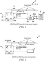
- MPN has to be built to transport air in the main channel MCH, while RPN transports air in the redundant channel RCH. This phase is presented in Fig. 1 , including the ASD, MPN, RPN and sampling holes.
- System 10 is illustrated in Figs. 1-5 illustrating various aspects of a process of determining which smoke sample point is active.
- System 10 is illustrated as installed in a region R, which might have a plurality of sub-sections.
- System 10 includes a main pipe network 12 and a substantially similar redundant pipe network 14 which is installed throughout the region R to provide smoke from a plurality of smoke sample points 18 formed in pipe networks 12, 14.
- the access points 18 for each of the networks 12, 14 are substantially identical.
- System 10 also includes a multi-channel aspirated smoke detector unit 20.
- Unit 20 includes fans or blowers, along with speed control circuitry 20-1, 20-2.
- the elements 20-1, -2 are in turn coupled to aspirated smoke, or gas, detector 20-3. None of the details of the elements 20-1, -2 or detector 20-3 are limitations hereof except to the extent described herein.
- System 10 includes control circuits 22 which can be implemented in part as a programmable processor 22a, and associated control software 22b.
- the control circuits are coupled to a visual or audible output device 22c which can provide a local output as to smoke or gas levels.
- Control circuits 22 can be coupled to unit 20 so as to control the fans 20-1, -2 and to receive ambient condition outputs such as smoke or gas levels from the detector 20-3.
- a storage unit 22d in either detector 20-3 or circuits 22 can be provided to store transport times associated with the sample points 18.
- Storage unit 22d can be implement with a variety of technologies without departing from the spirit and scope hereof.
- Circuits 22 can be coupled wired or wirelessly via a medium 24a to a displaced monitoring system control unit 24.
- Unit 24 can include a visual output device 24 to present information as to region R to a user.
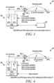
- Fig. 2 illustrates normal ASD operation.
- the MCH 20-1 fan is always working and aspirating air.
- the RCH fan 20-2 is not working, and so it is not aspirating air.
- a fire can develop; let's call this time instant as time 0.
- smoke enters a sampling hole 18-i of the MPN 12. This condition is illustrated in Fig. 3 .
- Smoke that has entered main pipe network 12 travels, for a transport time, to the unit 20.
- Tt transport time of the smoke from the sampling point 18-i to the ASD 20-3
- the ASD in conjunction with control circuits 22, indicates an alarm due to smoke sensed from the MCH 20-1.
- the smoke travels only in the main pipes MPN 12, because secondary fan 20-2 is stopped.
- only smoke that reaches MCH 20-1 indicates an alarm condition.
- the transport time is unknown.
- the transport time is defined as the time required for the smoke to travel from the sampling holes, such as 18-i, to the ASD.
- the transport time includes also the processing time of the sensor 20-3 and control circuits 22 to indicate the alarm. However, this doesn't affect any consideration or add any limitation to the determination of the location of sample point 18-i as those of skill will understand from reading this disclosure.
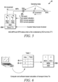
- a time counter is started inside the device.
- This counter can be located in the detector 20-3, or in the control circuits 22 without limitation.
- RCH 20-2 fan starts.
- the redundant channel fan 20-2 operates at the same speed of MCH fan 20-1.
- the RCH fan 20-2 pulls the smoke from the sample point 18-j in the RPN 14.
- Tt transport time
- the ASD indicates an alarm on the RCH 20-2, and the time counter is stopped.
- the time indicator in the counter can be stored in the unit 22d as illustrated in Fig. 5 .
- This time is designated as 2*Tt and the status of the system is illustrated in Fig. 5 . From this time measurement, it is possible to determine the location of the SSH, the smoke entry point 18-j, by comparison of measured Tt with the known transport time Ttx of every sample point 18-1, -2...-n where x is a generic hole.
- This transport time Ttx can be obtained in two ways as below.
- transit times Ttx(s) are calculated with software, then stored inside the memory, MEM 22d, of the device as Table 1 with an entry for each of the sample points 18-i.
- the power of the fan in terms of flow and pressure
- the pipe configuration in terms of geometry: pipe diameters, hole diameters and distance
- a different Table 2 can be obtained from testing activity on site, after the pipe installation.
- a cotton wick can be burned near every sampling hole, such as 18-1, -2 ...-n.
- a map of transport time, Table 2 can be obtained for the main pipe network 12 and stored inside the memory, MEM 22d, of the device.
- the final indication of the active smoke sample point can be displayed to the user in a different number of ways: for example (but not limited to) directly on the device such as at 22c, on a fire panel 24, such as at 24b, connected to the device, or on a computer connected to the device. If the SSH indication is provided in, or on the device, it can be displayed with (but not limited to) bar graph or in a LCD display.
- the RCH fan 20-2 To avoid dust/contamination or blockage in the RPN, it is useful to automatically and periodically activate the RCH fan 20-2. In this way, airflow will be checked with the standard equipment of ASD. Eventual malfunction of the RPN or RCH fans can be detected and proper maintenance can be ordered. It is a characteristic of this invention that, if the smoke enters more than one sampling hole in the main piping network 12, the related SSH indication will reflect the hole closest to the ASD.
- a redundant pipe system and independent fans are used to first detect a fire condition, and then, establish a transport time by using the redundant pipe system to make a second fire determination.
- the fans rotate in the same direction. No smoke clearing process is needed.
Landscapes
- General Physics & Mathematics (AREA)
- Physics & Mathematics (AREA)
- Chemical & Material Sciences (AREA)
- Analytical Chemistry (AREA)
- Engineering & Computer Science (AREA)
- Life Sciences & Earth Sciences (AREA)
- Health & Medical Sciences (AREA)
- Emergency Management (AREA)
- Business, Economics & Management (AREA)
- Computer Security & Cryptography (AREA)
- Biochemistry (AREA)
- Immunology (AREA)
- Pathology (AREA)
- General Health & Medical Sciences (AREA)
- Molecular Biology (AREA)
- Biomedical Technology (AREA)
- Fire-Detection Mechanisms (AREA)
- Fire Alarms (AREA)
Claims (1)
- Ansaugrauchdetektorsystem (10), umfassend:ein erstes Umgebungslufteingangsnetzwerk (12), das mit einem dauerbetriebenen ersten Ventilator (20-1) gekoppelt ist, wobei das erste Umgebungslufteingangsnetzwerk eine erste Vielzahl von beabstandeten Einlasspunkten (18) beinhaltet;ein zweites Umgebungslufteingangsnetzwerk (14), das mit einem zweiten Ventilator (20-2) gekoppelt ist, der sich von dem ersten Ventilator unterscheidet, wobei das zweite Umgebungslufteingangsnetzwerk eine zweite Vielzahl von beabstandeten Einlasspunkten (18) beinhaltet, wobei das erste Umgebungslufteingangsnetzwerk und das zweite Umgebungslufteingangsnetzwerk im Wesentlichen identisch sind, und wobei der erste Ventilator und der zweite Ventilator beide mit einer einheitlichen Drehzahl betrieben werden;einen Umgebungsbedingungsdetektor (20-3), der einen Mehrkanal-Ansaugrauchsensor mit primären und redundanten Raucherfassungskammern beinhaltet, die mit dem ersten Umgebungslufteingangsnetzwerk bzw. dem zweiten Umgebungslufteingangsnetzwerk gekoppelt sind;einen Zeitgeber; undSteuerschaltungen (22), die ausgestaltet sind, eine voraufgezeichnete Folge von Transportzeiten in Bezug auf die zweite Vielzahl von beabstandeten Einlasspunkten basierend auf einem Leistungswert hinsichtlich Durchfluss und Druck (Grundlage [0032], Zeile 40) des zweiten Ventilators und einer Rohrkonfiguration hinsichtlich Geometrie, Rohrdurchmessern, Lochdurchmessern und Abstand (Grundlage [0032], Zeile 41) des zweiten Umgebungslufteingangsnetzwerks zu berechnen und die voraufgezeichnete Folge von Transportzeiten als eine Tabelle in einer Speichervorrichtung (22d) zu speichern,wobei die Steuerschaltungen ausgestaltet sind, den zweiten Ventilator zu aktivieren, um Umgebungsluft einzusaugen, wenn von dem ersten Umgebungslufteingangsnetzwerk angesaugter Rauch einen Alarm in Zusammenhang mit dem Umgebungsbedingungsdetektor auslöst,wobei die Steuerschaltungen, gleichzeitig mit der Aktivierung des zweiten Ventilators, ausgestaltet sind, den Zeitgeber zu starten, um eine Transportzeit zwischen der Aktivierung des zweiten Ventilators und einem Zeitpunkt, zu dem der von dem zweiten Umgebungslufteingangsnetzwerk angesaugte Rauch den Umgebungsbedingungsdetektor erreicht, zu zählen, undwobei die Steuerschaltungen ausgestaltet sind, die Transportzeit mit der in der Speichervorrichtung gespeicherten voraufgezeichneten Folge von Transportzeiten zu vergleichen, um eine Position des Rauchs bereitzustellen,wobei der erste Ventilator und der zweite Ventilator in eine einheitliche Richtung rotieren, wenn die Transportzeit bestimmt wird, wobei jedes des ersten Umgebungslufteingangsnetzwerks und des zweiten Umgebungslufteingangsnetzwerks einen jeweiligen untereinander verbundenen Satz von Leitungen beinhaltet, die perforiert sind, um jeweils die erste Vielzahl von beabstandeten Einlasspunkten und die zweite Vielzahl von beabstandeten Einlasspunkten zu bilden,wobei der zweite Ventilator automatisch und periodisch aktiviert wird.
Applications Claiming Priority (1)
| Application Number | Priority Date | Filing Date | Title |
|---|---|---|---|
| US14/097,564 US9208671B2 (en) | 2013-12-05 | 2013-12-05 | Redundant input pipe networks in aspirated smoke detectors |
Publications (3)
| Publication Number | Publication Date |
|---|---|
| EP2881922A1 EP2881922A1 (de) | 2015-06-10 |
| EP2881922B1 EP2881922B1 (de) | 2019-05-29 |
| EP2881922B2 true EP2881922B2 (de) | 2025-05-21 |
Family
ID=52006824
Family Applications (1)
| Application Number | Title | Priority Date | Filing Date |
|---|---|---|---|
| EP14193553.6A Active EP2881922B2 (de) | 2013-12-05 | 2014-11-17 | Redundante Eingangsrohrnetzwerke in Rauchansaugmeldern |
Country Status (6)
| Country | Link |
|---|---|
| US (1) | US9208671B2 (de) |
| EP (1) | EP2881922B2 (de) |
| CN (1) | CN104700548B (de) |
| AU (1) | AU2014265133B2 (de) |
| CA (1) | CA2871612A1 (de) |
| ES (1) | ES2735631T3 (de) |
Families Citing this family (10)
| Publication number | Priority date | Publication date | Assignee | Title |
|---|---|---|---|---|
| CN106023513B (zh) * | 2016-06-25 | 2018-12-07 | 河北中核石辐科技有限责任公司 | 冗余烟雾探测器及系统 |
| US10169982B1 (en) * | 2017-07-03 | 2019-01-01 | Honeywell International Inc. | Systems and methods for delaying or activating a blowout device or a purge device in a sampling pipe network of an aspirated smoke detection system |
| CN109284512B (zh) | 2017-07-20 | 2023-12-26 | 开利公司 | 利用建筑信息模型实施光纤高灵敏度烟雾检测器系统 |
| EP3843057B1 (de) * | 2019-12-23 | 2022-11-16 | Carrier Corporation | Punktdetektor für feueralarmsystem |
| CN111273597A (zh) * | 2020-01-24 | 2020-06-12 | 西南石油大学 | 消防设施的集中监控巡检系统 |
| US12253503B2 (en) | 2020-10-17 | 2025-03-18 | Honeywell International Inc. | Modular aspirated smoke, gas, or air quality monitoring systems and devices |
| USD991067S1 (en) | 2020-10-17 | 2023-07-04 | Honeywell International Inc. | Modular aspirated smoke, gas, and air quality monitoring system device |
| CN113644568B (zh) * | 2021-09-26 | 2023-07-21 | 重庆吉能电气(集团)有限公司 | 一种户外防火型变电站 |
| CN115165480B (zh) * | 2022-07-01 | 2025-04-22 | 郑州轻工业大学 | 一种大型公共建筑火灾应急逃生检测设备 |
| US12037220B1 (en) * | 2023-07-21 | 2024-07-16 | The Adt Security Corporation | Systems for monitoring smoke and heat in elevator hoistways |
Family Cites Families (27)
| Publication number | Priority date | Publication date | Assignee | Title |
|---|---|---|---|---|
| JPH0496516U (de) * | 1991-01-30 | 1992-08-20 | ||
| DE4424909A1 (de) * | 1994-07-14 | 1996-01-18 | Siemens Ag | Verfahren und Vorrichtung zur Ortung von Schadstoffansammlungen |
| DE10114729A1 (de) * | 2001-03-22 | 2002-10-02 | Rittal Gmbh & Co Kg | Schaltschrank mit einer Rauchmeldeeinrichtung |
| DE50108478D1 (de) * | 2001-11-16 | 2006-01-26 | Piexon Ag Aarwangen | Vorrichtung mit einem Wirkstoff gefüllten bzw. füllbaren Speichertank und einer Vernebelungseinheit |
| US6786089B2 (en) * | 2002-03-28 | 2004-09-07 | Denso Corporation | Airflow meter |
| US6672255B1 (en) * | 2002-11-18 | 2004-01-06 | Carlos Zayas | Flue gas energy transfer system |
| DE10348565B4 (de) | 2003-10-20 | 2007-01-04 | Wagner Alarm- Und Sicherungssysteme Gmbh | Verfahren und Vorrichtung zum Erkennen und Lokalisieren eines Brandes |
| US7119700B2 (en) * | 2004-02-02 | 2006-10-10 | The Boeing Company | Apparatus and method for controlling an aircraft cooling and smoke system using discrete components |
| US7375642B2 (en) * | 2004-08-24 | 2008-05-20 | Wagner Alarm- Und Sicherungssysteme Gmbh | Method and device for identifying and localizing a fire |
| GB2430027A (en) | 2005-09-09 | 2007-03-14 | Kidde Ip Holdings Ltd | Fibre bragg temperature sensors |
| EP1811478B1 (de) | 2006-01-07 | 2008-04-02 | Hekatron Vertriebs GmbH | Verfahren und Vorrichtung zur Erkennung eines Brandes |
| US20100089240A1 (en) * | 2006-10-26 | 2010-04-15 | Krichtafovitch Igor A | Range hood with electrostatically assisted air flow and filtering |
| ATE517407T1 (de) * | 2007-05-16 | 2011-08-15 | Siemens Ag | Detektion und ortsbestimmung eines brandes |
| US20090253364A1 (en) * | 2008-04-07 | 2009-10-08 | Mark Henry | Rechargeable fire containment and smoke extraction system |
| DE102008028134A1 (de) | 2008-06-13 | 2009-12-17 | Fogtec Brandschutz Gmbh & Co. Kg | Branddetektion in Schienenfahrzeugen |
| US20100263882A1 (en) * | 2009-04-16 | 2010-10-21 | South-Tek Systems | System and method for fire protection system corrosion mitigation |
| JP5490585B2 (ja) * | 2009-05-29 | 2014-05-14 | 株式会社日立国際電気 | 基板処理装置、基板処理方法および半導体装置の製造方法 |
| AU2010255496B2 (en) * | 2009-06-05 | 2015-01-29 | Garrett Thermal Systems Limited | Gas detector apparatus |
| US9269248B2 (en) * | 2009-09-03 | 2016-02-23 | Life Safety Distribution Ag | Environmental parameter responsive, aspirated fire detector |
| GB2475306A (en) * | 2009-11-16 | 2011-05-18 | Groveley Detection Ltd | Temperature control apparatus including heat pipe for a gas or other detector that extends its operating range to extreme temperatures |
| CN102791352B (zh) * | 2010-03-05 | 2015-07-01 | 爱克斯崔里斯科技有限公司 | 过滤器旁路技术 |
| DE102010042700B4 (de) * | 2010-10-20 | 2013-12-24 | Siemens Aktiengesellschaft | Detektion und Ortsbestimmung eines Brandes mit einem Doppelrohr-Ansaugrauchmelder mit gemeinsamer Detektoreinheit |
| CN103688101B (zh) * | 2011-04-06 | 2015-11-25 | Pwi纯系统股份公司 | 含有烟雾探测器和信号装置的安全系统 |
| DE102011088150A1 (de) * | 2011-12-09 | 2013-06-13 | Kess-Tech Gmbh | Schalldämpfer-Anordnung |
| US9330550B2 (en) * | 2012-07-13 | 2016-05-03 | Walter Kidde Portable Equipment, Inc. | Low nuisance fast response hazard alarm |
| US9237681B2 (en) * | 2013-01-09 | 2016-01-12 | Io Data Centers, Llc | Modular data center |
| PL2862533T3 (pl) * | 2013-10-18 | 2019-12-31 | Erbe Elektromedizin Gmbh | Element adaptera, instrument chirurgiczny o wysokiej częstotliwości, zestaw i system adaptera |
-
2013
- 2013-12-05 US US14/097,564 patent/US9208671B2/en active Active
-
2014
- 2014-11-17 EP EP14193553.6A patent/EP2881922B2/de active Active
- 2014-11-17 ES ES14193553T patent/ES2735631T3/es active Active
- 2014-11-19 CA CA2871612A patent/CA2871612A1/en not_active Abandoned
- 2014-11-24 AU AU2014265133A patent/AU2014265133B2/en active Active
- 2014-12-04 CN CN201410727130.5A patent/CN104700548B/zh active Active
Also Published As
| Publication number | Publication date |
|---|---|
| CN104700548B (zh) | 2018-06-15 |
| ES2735631T3 (es) | 2019-12-19 |
| US20150161865A1 (en) | 2015-06-11 |
| US9208671B2 (en) | 2015-12-08 |
| EP2881922A1 (de) | 2015-06-10 |
| EP2881922B1 (de) | 2019-05-29 |
| CN104700548A (zh) | 2015-06-10 |
| CA2871612A1 (en) | 2015-06-05 |
| AU2014265133B2 (en) | 2016-12-08 |
| AU2014265133A1 (en) | 2015-06-25 |
Similar Documents
| Publication | Publication Date | Title |
|---|---|---|
| EP2881922B2 (de) | Redundante Eingangsrohrnetzwerke in Rauchansaugmeldern | |
| RU2342709C2 (ru) | Способ и устройство для обнаружения пожара и определения его места | |
| KR102077519B1 (ko) | 공기흡입식 연기감지 시스템 | |
| EP2840560B1 (de) | Belüfteter mehrkanaliger Rauchmelder | |
| TWI629670B (zh) | 微粒偵測系統及微粒偵測方法 | |
| EP2858052B1 (de) | Leitungsdetektor mit Fern-Luftstrom-Testfunktion | |
| US8629780B2 (en) | Method of detecting and localizing a fire based on a time difference and air speeds of monitored air in pipe conduits | |
| CN105917208A (zh) | 具有不同流修改的呼吸微粒探测 | |
| EP3843057B1 (de) | Punktdetektor für feueralarmsystem | |
| CN102054322A (zh) | 火灾传感器和火灾检测方法 | |
| EP3907484B1 (de) | Detektion von leckagen in einem ansaugbrandmeldesystem | |
| JP2009063313A (ja) | ガス漏洩監視システム | |
| US20240386789A1 (en) | Method and Test Device for Verifying the Functionality of an Intake Particle Detection System | |
| CN116482298A (zh) | 吸气式探测系统的监测 | |
| EP3023953B1 (de) | System und verfahren zur luftstromüberwachung für umgebungen mit variablem luftstrom | |
| US11189143B2 (en) | Aspiration smoke detection system | |
| US7573392B2 (en) | Backdraft detector | |
| US11935390B2 (en) | Fire detection system and method for identifying a source of smoke in a monitored environment | |
| CN117636560A (zh) | 具有测试模块的吸气式烟雾检测器 | |
| Grau et al. | Sniffer project development | |
| HK1213681B (zh) | 起火探测 |
Legal Events
| Date | Code | Title | Description |
|---|---|---|---|
| PUAI | Public reference made under article 153(3) epc to a published international application that has entered the european phase |
Free format text: ORIGINAL CODE: 0009012 |
|
| 17P | Request for examination filed |
Effective date: 20141117 |
|
| AK | Designated contracting states |
Kind code of ref document: A1 Designated state(s): AL AT BE BG CH CY CZ DE DK EE ES FI FR GB GR HR HU IE IS IT LI LT LU LV MC MK MT NL NO PL PT RO RS SE SI SK SM TR |
|
| AX | Request for extension of the european patent |
Extension state: BA ME |
|
| STAA | Information on the status of an ep patent application or granted ep patent |
Free format text: STATUS: EXAMINATION IS IN PROGRESS |
|
| 17Q | First examination report despatched |
Effective date: 20170727 |
|
| GRAP | Despatch of communication of intention to grant a patent |
Free format text: ORIGINAL CODE: EPIDOSNIGR1 |
|
| STAA | Information on the status of an ep patent application or granted ep patent |
Free format text: STATUS: GRANT OF PATENT IS INTENDED |
|
| INTG | Intention to grant announced |
Effective date: 20190109 |
|
| RIN1 | Information on inventor provided before grant (corrected) |
Inventor name: SUSEL, MICHELE Inventor name: CERNOIA, FEDERICO |
|
| GRAS | Grant fee paid |
Free format text: ORIGINAL CODE: EPIDOSNIGR3 |
|
| GRAA | (expected) grant |
Free format text: ORIGINAL CODE: 0009210 |
|
| STAA | Information on the status of an ep patent application or granted ep patent |
Free format text: STATUS: THE PATENT HAS BEEN GRANTED |
|
| AK | Designated contracting states |
Kind code of ref document: B1 Designated state(s): AL AT BE BG CH CY CZ DE DK EE ES FI FR GB GR HR HU IE IS IT LI LT LU LV MC MK MT NL NO PL PT RO RS SE SI SK SM TR |
|
| REG | Reference to a national code |
Ref country code: GB Ref legal event code: FG4D |
|
| REG | Reference to a national code |
Ref country code: CH Ref legal event code: EP |
|
| REG | Reference to a national code |
Ref country code: AT Ref legal event code: REF Ref document number: 1138726 Country of ref document: AT Kind code of ref document: T Effective date: 20190615 |
|
| REG | Reference to a national code |
Ref country code: DE Ref legal event code: R096 Ref document number: 602014047521 Country of ref document: DE |
|
| REG | Reference to a national code |
Ref country code: IE Ref legal event code: FG4D |
|
| REG | Reference to a national code |
Ref country code: NL Ref legal event code: MP Effective date: 20190529 |
|
| REG | Reference to a national code |
Ref country code: LT Ref legal event code: MG4D |
|
| PG25 | Lapsed in a contracting state [announced via postgrant information from national office to epo] |
Ref country code: HR Free format text: LAPSE BECAUSE OF FAILURE TO SUBMIT A TRANSLATION OF THE DESCRIPTION OR TO PAY THE FEE WITHIN THE PRESCRIBED TIME-LIMIT Effective date: 20190529 Ref country code: LT Free format text: LAPSE BECAUSE OF FAILURE TO SUBMIT A TRANSLATION OF THE DESCRIPTION OR TO PAY THE FEE WITHIN THE PRESCRIBED TIME-LIMIT Effective date: 20190529 Ref country code: NO Free format text: LAPSE BECAUSE OF FAILURE TO SUBMIT A TRANSLATION OF THE DESCRIPTION OR TO PAY THE FEE WITHIN THE PRESCRIBED TIME-LIMIT Effective date: 20190829 Ref country code: FI Free format text: LAPSE BECAUSE OF FAILURE TO SUBMIT A TRANSLATION OF THE DESCRIPTION OR TO PAY THE FEE WITHIN THE PRESCRIBED TIME-LIMIT Effective date: 20190529 Ref country code: SE Free format text: LAPSE BECAUSE OF FAILURE TO SUBMIT A TRANSLATION OF THE DESCRIPTION OR TO PAY THE FEE WITHIN THE PRESCRIBED TIME-LIMIT Effective date: 20190529 Ref country code: AL Free format text: LAPSE BECAUSE OF FAILURE TO SUBMIT A TRANSLATION OF THE DESCRIPTION OR TO PAY THE FEE WITHIN THE PRESCRIBED TIME-LIMIT Effective date: 20190529 Ref country code: PT Free format text: LAPSE BECAUSE OF FAILURE TO SUBMIT A TRANSLATION OF THE DESCRIPTION OR TO PAY THE FEE WITHIN THE PRESCRIBED TIME-LIMIT Effective date: 20190930 |
|
| PG25 | Lapsed in a contracting state [announced via postgrant information from national office to epo] |
Ref country code: BG Free format text: LAPSE BECAUSE OF FAILURE TO SUBMIT A TRANSLATION OF THE DESCRIPTION OR TO PAY THE FEE WITHIN THE PRESCRIBED TIME-LIMIT Effective date: 20190829 Ref country code: RS Free format text: LAPSE BECAUSE OF FAILURE TO SUBMIT A TRANSLATION OF THE DESCRIPTION OR TO PAY THE FEE WITHIN THE PRESCRIBED TIME-LIMIT Effective date: 20190529 Ref country code: GR Free format text: LAPSE BECAUSE OF FAILURE TO SUBMIT A TRANSLATION OF THE DESCRIPTION OR TO PAY THE FEE WITHIN THE PRESCRIBED TIME-LIMIT Effective date: 20190830 Ref country code: LV Free format text: LAPSE BECAUSE OF FAILURE TO SUBMIT A TRANSLATION OF THE DESCRIPTION OR TO PAY THE FEE WITHIN THE PRESCRIBED TIME-LIMIT Effective date: 20190529 |
|
| REG | Reference to a national code |
Ref country code: AT Ref legal event code: MK05 Ref document number: 1138726 Country of ref document: AT Kind code of ref document: T Effective date: 20190529 |
|
| REG | Reference to a national code |
Ref country code: ES Ref legal event code: FG2A Ref document number: 2735631 Country of ref document: ES Kind code of ref document: T3 Effective date: 20191219 |
|
| PG25 | Lapsed in a contracting state [announced via postgrant information from national office to epo] |
Ref country code: EE Free format text: LAPSE BECAUSE OF FAILURE TO SUBMIT A TRANSLATION OF THE DESCRIPTION OR TO PAY THE FEE WITHIN THE PRESCRIBED TIME-LIMIT Effective date: 20190529 Ref country code: NL Free format text: LAPSE BECAUSE OF FAILURE TO SUBMIT A TRANSLATION OF THE DESCRIPTION OR TO PAY THE FEE WITHIN THE PRESCRIBED TIME-LIMIT Effective date: 20190529 Ref country code: AT Free format text: LAPSE BECAUSE OF FAILURE TO SUBMIT A TRANSLATION OF THE DESCRIPTION OR TO PAY THE FEE WITHIN THE PRESCRIBED TIME-LIMIT Effective date: 20190529 Ref country code: DK Free format text: LAPSE BECAUSE OF FAILURE TO SUBMIT A TRANSLATION OF THE DESCRIPTION OR TO PAY THE FEE WITHIN THE PRESCRIBED TIME-LIMIT Effective date: 20190529 Ref country code: CZ Free format text: LAPSE BECAUSE OF FAILURE TO SUBMIT A TRANSLATION OF THE DESCRIPTION OR TO PAY THE FEE WITHIN THE PRESCRIBED TIME-LIMIT Effective date: 20190529 Ref country code: RO Free format text: LAPSE BECAUSE OF FAILURE TO SUBMIT A TRANSLATION OF THE DESCRIPTION OR TO PAY THE FEE WITHIN THE PRESCRIBED TIME-LIMIT Effective date: 20190529 Ref country code: SK Free format text: LAPSE BECAUSE OF FAILURE TO SUBMIT A TRANSLATION OF THE DESCRIPTION OR TO PAY THE FEE WITHIN THE PRESCRIBED TIME-LIMIT Effective date: 20190529 |
|
| PG25 | Lapsed in a contracting state [announced via postgrant information from national office to epo] |
Ref country code: SM Free format text: LAPSE BECAUSE OF FAILURE TO SUBMIT A TRANSLATION OF THE DESCRIPTION OR TO PAY THE FEE WITHIN THE PRESCRIBED TIME-LIMIT Effective date: 20190529 |
|
| REG | Reference to a national code |
Ref country code: DE Ref legal event code: R026 Ref document number: 602014047521 Country of ref document: DE |
|
| PLBI | Opposition filed |
Free format text: ORIGINAL CODE: 0009260 |
|
| PLAX | Notice of opposition and request to file observation + time limit sent |
Free format text: ORIGINAL CODE: EPIDOSNOBS2 |
|
| PG25 | Lapsed in a contracting state [announced via postgrant information from national office to epo] |
Ref country code: TR Free format text: LAPSE BECAUSE OF FAILURE TO SUBMIT A TRANSLATION OF THE DESCRIPTION OR TO PAY THE FEE WITHIN THE PRESCRIBED TIME-LIMIT Effective date: 20190529 |
|
| 26 | Opposition filed |
Opponent name: HEKATRON VERTRIEBS GMBH Effective date: 20200228 |
|
| PG25 | Lapsed in a contracting state [announced via postgrant information from national office to epo] |
Ref country code: PL Free format text: LAPSE BECAUSE OF FAILURE TO SUBMIT A TRANSLATION OF THE DESCRIPTION OR TO PAY THE FEE WITHIN THE PRESCRIBED TIME-LIMIT Effective date: 20190529 |
|
| PG25 | Lapsed in a contracting state [announced via postgrant information from national office to epo] |
Ref country code: SI Free format text: LAPSE BECAUSE OF FAILURE TO SUBMIT A TRANSLATION OF THE DESCRIPTION OR TO PAY THE FEE WITHIN THE PRESCRIBED TIME-LIMIT Effective date: 20190529 |
|
| REG | Reference to a national code |
Ref country code: CH Ref legal event code: PL |
|
| PLBB | Reply of patent proprietor to notice(s) of opposition received |
Free format text: ORIGINAL CODE: EPIDOSNOBS3 |
|
| PG25 | Lapsed in a contracting state [announced via postgrant information from national office to epo] |
Ref country code: LI Free format text: LAPSE BECAUSE OF NON-PAYMENT OF DUE FEES Effective date: 20191130 Ref country code: LU Free format text: LAPSE BECAUSE OF NON-PAYMENT OF DUE FEES Effective date: 20191117 Ref country code: CH Free format text: LAPSE BECAUSE OF NON-PAYMENT OF DUE FEES Effective date: 20191130 Ref country code: MC Free format text: LAPSE BECAUSE OF FAILURE TO SUBMIT A TRANSLATION OF THE DESCRIPTION OR TO PAY THE FEE WITHIN THE PRESCRIBED TIME-LIMIT Effective date: 20190529 |
|
| REG | Reference to a national code |
Ref country code: BE Ref legal event code: MM Effective date: 20191130 |
|
| PG25 | Lapsed in a contracting state [announced via postgrant information from national office to epo] |
Ref country code: IT Free format text: LAPSE BECAUSE OF NON-PAYMENT OF DUE FEES Effective date: 20191117 Ref country code: IE Free format text: LAPSE BECAUSE OF NON-PAYMENT OF DUE FEES Effective date: 20191117 |
|
| PG25 | Lapsed in a contracting state [announced via postgrant information from national office to epo] |
Ref country code: BE Free format text: LAPSE BECAUSE OF NON-PAYMENT OF DUE FEES Effective date: 20191130 |
|
| REG | Reference to a national code |
Ref country code: ES Ref legal event code: FD2A Effective date: 20210526 |
|
| PG25 | Lapsed in a contracting state [announced via postgrant information from national office to epo] |
Ref country code: CY Free format text: LAPSE BECAUSE OF FAILURE TO SUBMIT A TRANSLATION OF THE DESCRIPTION OR TO PAY THE FEE WITHIN THE PRESCRIBED TIME-LIMIT Effective date: 20190529 |
|
| PG25 | Lapsed in a contracting state [announced via postgrant information from national office to epo] |
Ref country code: IS Free format text: LAPSE BECAUSE OF FAILURE TO SUBMIT A TRANSLATION OF THE DESCRIPTION OR TO PAY THE FEE WITHIN THE PRESCRIBED TIME-LIMIT Effective date: 20190929 |
|
| PG25 | Lapsed in a contracting state [announced via postgrant information from national office to epo] |
Ref country code: MT Free format text: LAPSE BECAUSE OF FAILURE TO SUBMIT A TRANSLATION OF THE DESCRIPTION OR TO PAY THE FEE WITHIN THE PRESCRIBED TIME-LIMIT Effective date: 20190529 Ref country code: HU Free format text: LAPSE BECAUSE OF FAILURE TO SUBMIT A TRANSLATION OF THE DESCRIPTION OR TO PAY THE FEE WITHIN THE PRESCRIBED TIME-LIMIT; INVALID AB INITIO Effective date: 20141117 |
|
| PG25 | Lapsed in a contracting state [announced via postgrant information from national office to epo] |
Ref country code: ES Free format text: LAPSE BECAUSE OF NON-PAYMENT OF DUE FEES Effective date: 20191118 |
|
| PLCK | Communication despatched that opposition was rejected |
Free format text: ORIGINAL CODE: EPIDOSNREJ1 |
|
| APAH | Appeal reference modified |
Free format text: ORIGINAL CODE: EPIDOSCREFNO |
|
| APBM | Appeal reference recorded |
Free format text: ORIGINAL CODE: EPIDOSNREFNO |
|
| APBP | Date of receipt of notice of appeal recorded |
Free format text: ORIGINAL CODE: EPIDOSNNOA2O |
|
| APBQ | Date of receipt of statement of grounds of appeal recorded |
Free format text: ORIGINAL CODE: EPIDOSNNOA3O |
|
| PG25 | Lapsed in a contracting state [announced via postgrant information from national office to epo] |
Ref country code: MK Free format text: LAPSE BECAUSE OF FAILURE TO SUBMIT A TRANSLATION OF THE DESCRIPTION OR TO PAY THE FEE WITHIN THE PRESCRIBED TIME-LIMIT Effective date: 20190529 |
|
| APAH | Appeal reference modified |
Free format text: ORIGINAL CODE: EPIDOSCREFNO |
|
| APBU | Appeal procedure closed |
Free format text: ORIGINAL CODE: EPIDOSNNOA9O |
|
| PGFP | Annual fee paid to national office [announced via postgrant information from national office to epo] |
Ref country code: DE Payment date: 20241128 Year of fee payment: 11 |
|
| PGFP | Annual fee paid to national office [announced via postgrant information from national office to epo] |
Ref country code: GB Payment date: 20241126 Year of fee payment: 11 |
|
| PGFP | Annual fee paid to national office [announced via postgrant information from national office to epo] |
Ref country code: FR Payment date: 20241126 Year of fee payment: 11 |
|
| PUAH | Patent maintained in amended form |
Free format text: ORIGINAL CODE: 0009272 |
|
| STAA | Information on the status of an ep patent application or granted ep patent |
Free format text: STATUS: PATENT MAINTAINED AS AMENDED |
|
| 27A | Patent maintained in amended form |
Effective date: 20250521 |
|
| AK | Designated contracting states |
Kind code of ref document: B2 Designated state(s): AL AT BE BG CH CY CZ DE DK EE ES FI FR GB GR HR HU IE IS IT LI LT LU LV MC MK MT NL NO PL PT RO RS SE SI SK SM TR |
|
| REG | Reference to a national code |
Ref country code: DE Ref legal event code: R102 Ref document number: 602014047521 Country of ref document: DE |