EP2881201B1 - Schneidwerkzeug - Google Patents
Schneidwerkzeug Download PDFInfo
- Publication number
- EP2881201B1 EP2881201B1 EP13196190.6A EP13196190A EP2881201B1 EP 2881201 B1 EP2881201 B1 EP 2881201B1 EP 13196190 A EP13196190 A EP 13196190A EP 2881201 B1 EP2881201 B1 EP 2881201B1
- Authority
- EP
- European Patent Office
- Prior art keywords
- rim
- cutting
- disposable
- central line
- peripheral side
- Prior art date
- Legal status (The legal status is an assumption and is not a legal conclusion. Google has not performed a legal analysis and makes no representation as to the accuracy of the status listed.)
- Active
Links
- 238000005520 cutting process Methods 0.000 claims description 133
- 230000002093 peripheral effect Effects 0.000 claims description 35
- 238000004519 manufacturing process Methods 0.000 description 2
- 239000002184 metal Substances 0.000 description 2
- QNRATNLHPGXHMA-XZHTYLCXSA-N (r)-(6-ethoxyquinolin-4-yl)-[(2s,4s,5r)-5-ethyl-1-azabicyclo[2.2.2]octan-2-yl]methanol;hydrochloride Chemical compound Cl.C([C@H]([C@H](C1)CC)C2)CN1[C@@H]2[C@H](O)C1=CC=NC2=CC=C(OCC)C=C21 QNRATNLHPGXHMA-XZHTYLCXSA-N 0.000 description 1
- 239000000463 material Substances 0.000 description 1
- 238000004663 powder metallurgy Methods 0.000 description 1
Images


Classifications
-
- B—PERFORMING OPERATIONS; TRANSPORTING
- B23—MACHINE TOOLS; METAL-WORKING NOT OTHERWISE PROVIDED FOR
- B23B—TURNING; BORING
- B23B27/00—Tools for turning or boring machines; Tools of a similar kind in general; Accessories therefor
- B23B27/14—Cutting tools of which the bits or tips or cutting inserts are of special material
- B23B27/141—Specially shaped plate-like cutting inserts, i.e. length greater or equal to width, width greater than or equal to thickness
- B23B27/145—Specially shaped plate-like cutting inserts, i.e. length greater or equal to width, width greater than or equal to thickness characterised by having a special shape
-
- B—PERFORMING OPERATIONS; TRANSPORTING
- B23—MACHINE TOOLS; METAL-WORKING NOT OTHERWISE PROVIDED FOR
- B23C—MILLING
- B23C5/00—Milling-cutters
- B23C5/16—Milling-cutters characterised by physical features other than shape
- B23C5/20—Milling-cutters characterised by physical features other than shape with removable cutter bits or teeth or cutting inserts
- B23C5/202—Plate-like cutting inserts with special form
-
- B—PERFORMING OPERATIONS; TRANSPORTING
- B44—DECORATIVE ARTS
- B44B—MACHINES, APPARATUS OR TOOLS FOR ARTISTIC WORK, e.g. FOR SCULPTURING, GUILLOCHING, CARVING, BRANDING, INLAYING
- B44B11/00—Artists' hand tools for sculpturing, kneading, carving, engraving, guilloching or embossing; Accessories therefor
- B44B11/02—Artists' hand tools for sculpturing, kneading, carving, engraving, guilloching or embossing; Accessories therefor for substantially two-dimensional carving, engraving or guilloching
Definitions
- the present invention relates to a carving cutter comprising a cutter arbor and a disposable carving blade.
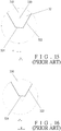
- a carving cutter 30 is made of carbidc material and contains a cutter arbor 31 and a cutting portion 32, wherein the cutting portion 32 is comprised of a flatly top surface 321 located at a first central line 320 of the cutting portion 32, a right cutting rim 322, a left cutting rim 323, and a cutting edge 324 arranged at five degrees relative to a level.
- FIG. 13 A conventional carving cutter is applied to carve letters, images or patterns on a metal workpiece.
- a distance between the first central line 320 of the cutting portion 32 and a second central line 310 of the cutter arbor 31 is an eccentric value e
- a width radius Y is defined between a distal end of the cutting edge 324 and the second central line 310
- a slot width cut by the carving cutter 30 is 2Y.
- the carving cutter 30 is used to perform a cutting of little volume based on a designed eccentric value e, so only the right cutting rim 322 and the cutting edge 324 can be used to carve the workpiece.
- the eccentric value e is selectively changed to cooperate with the width radiuses Y, wherein the eccentric value e is ranged within 0.01 to 0.06 mm and the width radius Y is ranged within 0.05 to 0.3 mm.
- the user when a user desires to carve slots with various slot widths, the user has to buy multiple carving cutters 30 of which eccentric values e (or width radiuses Y) are different.
- the cutting edge 324 and the right cutting rim 322 are not sharp, they are ground by a grinding machine, but a size of the cutting edge 324 is quite small, so it cannot be ground exactly.
- the right cutting rim 322 and the left cutting rim 323 both have to be ground precisely, or the eccentric value e defined between the first central line 320 of the cutting portion 32 and the second central line 310 of the cutter arbor 31 changes so that the width radius Y changes as well.
- the eccentric value e increases to over the set value
- the cutting edge 324 is located at the right side of the second central line 310, and the left cutting rim 323 extends to the right side of the second central line 310 (as shown in FIG. 16 ), such that the carving cutter 30 cannot cut the workpiece smoothly, thereby causing improper cutting precision.
- FIG. 17 shows a conventional disposable carving cutter 40, which contains a cutter arbor 41 and a holder 42 fixed on a distal end of the cutter arbor 41.
- the holder 42 has a screw orifice 421, a distance between a central position of the screw orifice 421 and a first central line 400 of the cutter arbor 41 is an eccentric value e.
- the screw orifice 421 of the holder 42 is provided to lock a disposable carving blade 50.
- the disposable carving blade 50 is in a rhombus shape and includes a right cutting rim 51 and a left cutting rim 52 between which is defined a V-shaped portion.
- the V-shapes portion has a cutting edge 53 formed on a distal end thereof, and the right cutting rim 51 is symmetrical to the left cutting rim 52, wherein an intersection point of distal ends of the right cutting rim 51 and the left cutting rim 52 is located at a second central line 500 of the disposable carving blade 50, and a stepped aperture 54 is defined at central position of the disposable carving blade 50, wherein the stepped aperture 54 corresponds to the screw orifice 421, and the second central line 500 passes through central positions of the screw orifice 421 and the stepped aperture 54.
- a distance between a distal end of the cutting edge 53 and the first central line 400 of the cutter arbor 41 is a width radius Y, and only the right cutting rim 51 and the cutting edge 53 can cut workpiece.
- a new disposable carving blade 50 has to cooperate with a holder 42 with a fit eccentric value e so that the cutting edge 53 and the left cutting rim 52 cannot rightward move away from the first central line 400.
- the eccentric value e is set on the cutter arbor 41 (i.e.
- the present invention has arisen to mitigate and/or obviate the afore-described disadvantages.
- US 5,779,400 A discloses a small-shank cutting tool for a swiss type automatic lathe.
- a rhomboidal-shaped tool insert of the cutting tool is seated within the tool recess of the shank with two sides of the insert, each engaging a respective tool-supporting surface of the shank.
- US 6,217,263 B1 discloses a rhombic shaped metal cutting insert adapted for longitudinal turning and copy turning. Opposite nose corners of the insert form equal angles less than 60 degrees.
- WO 03/089203 A1 discloses a gear hobbing cutter system which includes a cutter head body having a plurality of cartridge-receiving slots arranged in pairs comprising an inside and an outside cartridge-receiving slot.
- US 6 220 795 B1 discloses a disposable carving blade according to the preamble of claim 1.
- the primary object of the present invention is to provide a carving cutter comprising a cutter arbor and a disposable carving blade which matches with a cutter arbor that is eccentric or is not eccentric.
- Another object of the present invention is to provide a carving cutter by which a first eccentric value can be changed by merely replacing the disposable carving blade with another one disposable carving blade without replacing the cutter arbor so as to save use cost.
- a disposable carving blade is substantially formed in a parallelogram shape and contains a central hole defined at a central position thereof, a first central line passing through the central position thereof, a right cutting rim formed on a first peripheral side thereof and a left cutting rim formed on a second peripheral side thereof, wherein the right cutting rim is connected with the left cutting rim to form a V-shaped portion, the V-shaped portion includes a cutting edge defined on a distal end thereof, wherein the first central line passes through the cutting edge, and wherein a length of the right cutting rim on the first peripheral side of the disposable carving blade is shorter than a length of the left cutting rim on the second peripheral side of the disposable carving blade so that a theoretical intersection point of the right cutting rim on the first peripheral side of the disposable carving blade and the left cutting rim on the second peripheral side of the disposable carving blade is adjacent to the first central line, and a distance between the intersection point and the first central line is a first eccentric value
- a length of the right cutting rim is not symmetrical to that of the left cutting rim.
- the disposable carving blade also contains a right cutting rim arranged on a third peripheral side thereof symmetrical and parallel to the right cutting rim on the first peripheral side of the disposable carving blade and contains another left cutting rim arranged on a fourth peripheral side thereof symmetrical and parallel to the left cutting rim on the second peripheral side of the disposable carving blade, wherein a distance between the two left cutting rims is a first rim spacing value, and a distance between the two right cutting rims is a second rim spacing value.
- intersection point is located beside a right side of the first central line, and the first rim spacing value defined between the two left cutting rims is less than the second rim spacing value defined between the two right cutting rims.
- intersection point is located beside a left side of the first central line, and the second rim spacing value defined between the two right cutting rims is less than the first rim spacing value defined between the two left cutting rims.
- an intersection point of the right cutting rim on the first peripheral side of the disposable carving blade and the left cutting rim on the second peripheral side of the disposable carving blade is adjacent to the first central line, and a distance between the intersection point and the first central line is a first eccentric value, a width radius is defined between a distal end of the cutting edge and the first central line, and the eccentric value is set based on using requirement.
- a length of the right cutting rim is not symmetrical to that of the left cutting rim, and the intersection point is adjacent to the first central line, such that the first rim spacing value and the second rim spacing value is different.
- the first eccentric value changes according to the difference between the first rim spacing value and the second rim spacing value.
- a disposable carving blade 10 comprises a central hole 11 defined at a central position thereof, a first central line 15 passing through the central position thereof, a right cutting rim 12 formed on a first peripheral side thereof and a left cutting rim 13 formed on a second peripheral side thereof, wherein the right cutting rim 12 is connected with the left cutting rim 13 to form a V-shaped portion, the V-shaped portion includes a cutting edge 14 defined on a distal end thereof.
- the disposable carving blade 10 also comprises another right cutting rim 12 arranged on a third peripheral side thereof symmetrical and parallel to the right cutting rim 12 on the first peripheral side of the disposable carving blade 10 and comprises another left cutting rim 13 arranged on a fourth peripheral side thereof symmetrical and parallel to the left cutting rim 13 on the second peripheral side of the disposable carving blade 10.
- a distance between the two left cutting rims 13 is a first rim spacing value L1
- a distance between the two right cutting rims 12 is a second rim spacing value L2.
- An intersection point of the right cutting rim 12 on the first peripheral side of the disposable carving blade 10 and the left cutting rim 13 on the second peripheral side of the disposable carving blade 10 is adjacent to the first central line 15, and a distance between the intersection point and the first central line 15 is a first eccentric value e, a width radius Y is defined between a distal end of the cutting edge 14 and the first central line 15, and the first eccentric value e is set based on using requirement.
- each right cutting rim 12 Since a length of each right cutting rim 12 is not symmetrical to that of each left cutting rim 13, and the intersection point is not located at the first central line 15 (i.e., is adjacent to the first central line 15), the first rim spacing value L1 defined between the two left cutting rims 13 is different from the second rim spacing value L2 defined between the two right cutting rims 12.
- the disposable carving blade 10 is substantially formed in a parallelogram shape, and when the intersection point of the right cutting rim 12 on the first peripheral side of the disposable carving blade 10 and the left cutting rim 13 on the second peripheral side of the disposable carving blade 10 is located beside the right side of the first central line 15, the length of the right cutting rim 12 is shorter than that of the left cutting rim 13. That is, the second rim spacing value L2 defined between the two right cutting rims 12 is larger than the first rim spacing value L1 defined between the two left cutting rims, and when a difference between the first rim spacing value L1 and the second rim spacing value L2 changes, the first eccentric value e changes accordingly.
- a cutter arbor 20 includes a holder 21 on a distal end thereof and a second central line 200 defined thereon.
- the holder 21 has a screw orifice 211 formed at a central position thereof, wherein the second central line 200 of the cutter arbor 20 passes through a central point of the screw orifice 211 of the holder 21, i.e., the holder 21 is not eccentric relative to the cutter arbor 20.
- the central hole 11 of the disposable carving blade 10 corresponds in shape to the screw orifice 211 of the holder 21 so that the disposable carving blade 10 is locked in the screw orifice 211 of the holder 21.
- the first eccentric value e is produced by merely arranging the right cutting rim 12 asymmetrically to the left cutting rim 13 of the disposable carving blade 10, and when a length of each right cutting rim 12 and that of each left cutting rim 13 are changed, the first eccentric value e is also changed.
- the first eccentric value e of the disposable carving blade 10 is 0.01 mm
- the width radius Y is 0.05 mm
- a width of a slot cut by the disposable carving blade 10 is 0.1 mm, wherein the disposable carving blade 10 is locked on the holder 21 of the cutter arbor 20.
- the second central line 200 of the cutter arbor 20 passes through the central point of the screw orifice 211 of the holder 21, i.e., the holder 21 is not eccentric relative to the cutter arbor 20.
- the left cutting rim 13 on the second peripheral side of the disposable carving blade 10 does not extend to the right side of the second central line 200, such that the left cutting rim 13 cannot interfere a cutting process.
- the cutting edge 14 becomes dull
- the disposable carving blade 10 is rotated upside down to cut a workpiece by ways of another cutting edge 14.
- a new disposable carving blade 10 is used to replace the dull disposable carving blade 10.
- the first eccentric value e of the disposable carving blade 10 is 0.02 mm
- the width radius Y is 0.1 mm
- a width of a slot cut by the disposable carving blade 10 is 0.2 mm, wherein the disposable carving blade 10 is locked on the holder 21 of the cutter arbor 20.
- the second central line 200 of the cutter arbor 20 passes through the central point of the screw orifice 211 of the holder 21, i.e., the holder 21 is not eccentric relative to the cutter arbor 20.
- the left cutting rim 13 on the second peripheral side of the disposable carving blade 10 does not extend to the right side of the second central line 200, such that the left cutting rim 13 cannot interfere the cutting process.
- the cutting edge 14 becomes dull
- the disposable carving blade 10 is rotated upside down to cut the workpiece by ways of another cutting edge 14.
- a new disposable carving blade 10 is applied to replace the dull disposable carving blade 10.
- the first eccentric value e of the disposable carving blade 10 is 0.03 mm
- the width radius Y is 0.15 mm
- a width of a slot cut by the disposable carving blade 10 is 0.3 mm, wherein the disposable carving blade 10 is locked on the holder 21 of the cutter arbor 20.
- the second central line 200 of the cutter arbor 20 passes through the central point of the screw orifice 211 of the holder 21, i.e., the holder 21 is not eccentric relative to the cutter arbor 20.
- the left cutting rim 13 on the second peripheral side of the disposable carving blade 10 does not extend to the right side of the second central line 200, such that the left cutting rim 13 cannot interfere the cutting process.
- the cutting edge 14 becomes dull
- the disposable carving blade 10 is rotated upside down to cut a workpiece by ways of another cutting edge 14. Furthermore, a new disposable carving blade 10 is served to replace the dull disposable carving blade 10.
- the user can change the width radius Y as well as the first eccentric value e by merely selecting a desired disposable carving blade 10 without replacing the cutter arbor 20, such that the assembly between the cutter arbor 20 and the disposable carving blade 10 is facilitated.
- the disposable carving blade 10 is manufactured by means of powder metallurgy, so the first eccentric value e is formed directly without being ground, thereby lowering production cost and improving manufacturing accuracy.
- the disposable carving blade 10 can also cooperate with another holder 21 which includes a third central line 2110 passing through the central position of the screw orifice 211, and a second eccentric value E is defined between the third central line 2110 and the second central line 200 of the cutter arbor 20.
- the second eccentric value E is set according to using requirement so as to increase the width radius Y. In other words, the width radius Y can be changed by merely replacing the cutter arbor 20 without replacing the disposable carving blade 10.
- the user can merely replace the disposable carving blade 10 or the cutter arbor 20 to achieve various slot widths, thereby saving using cost and avoiding assembling the cutter arbor 20 and the disposable carving blade 10 in different specification.
Landscapes
- Engineering & Computer Science (AREA)
- Mechanical Engineering (AREA)
- Milling Processes (AREA)
Claims (5)
- Ein Schnitzmesser, umfassend einen Fräsdorn (20) und eine Einweg-Schnitzklinge (10), die im Wesentlichen parallelförmig gebildet sind, wobei die Einweg-Schnitzklinge (10) die folgenden Elemente umfasst: ein Mittelloch (11), das in deren Mitte gebildet ist; eine erste Zentrallinie (15), die durch deren mittlere Position verläuft und parallel zu einer zweiten Zentrallinie (200) des Fräsdorns (20) ausgerichtet ist; eine Schneidkante (12) auf deren ersten peripheralen Seite und eine linke Schneidkante (13) auf deren zweiten peripheralen Seite gebildet sind, dadurch gekennzeichnet, dass die rechte Schneidkante (12) mit der linken Schneidkante (13) verbunden ist, um einen V-förmigen Teil zu bilden, der V-förmige Teil eine Schnittkante (14) aufweist, die an dessen distalen Ende gebildet ist; wobei die erste Zentrallinie (15) durch die Schnittkante (14) verläuft und eine Länge der rechten Schneidkante (12) auf der ersten peripheralen Seite der Einweg-Schnitzklinge kürzer als eine Länge der linken Schneidkante (13) auf der zweiten peripheralen Seiten der Einweg-Schnitzklinge ist, so dass ein theoretischer Schnittpunkt der rechten Schneidkante (12) auf der ersten peripheralen Seite der Einweg-Schnitzklinge und der linken Schneidkante (13) auf der zweiten peripheralen Seite der Einweg-Schnitzklinge (10) an die erste Zentrallinie (15) angrenzt, während ein Abstand zwischen dem Schnittpunkt und der ersten Zentrallinie (15) ein erster exzentrischer Wert (e) ist.
- Das Schnitzmesser nach Anspruch 1, wobei eine Länge der rechten Schneidkante (12) nicht mit jener der linken Schneidkante (13) symmetrisch ist.
- Das Schnitzmesser nach Anspruch 2, weiter umfassend eine weitere rechte Schneidkante (12), die auf dessen dritten peripheralen Seite und symmetrisch und parallel zur rechten Schneidkante (12) auf der ersten peripheralen Seite der Einweg-Schnitzklinge verläuft und eine weitere linke Schneidkante (13) umfasst, die auf dessen vierten peripheralen Seite und symmetrisch und parallel zur rechten Schneidkante (12) auf der ersten peripheralen Seite der Einweg-Schnitzklinge verläuft und eine weitere linke Schneidkante (13) umfasst, die auf dessen vierten peripheralen Seite und symmetrisch und parallel zur linken Schneidkante (13) auf der zweiten peripheralen Seite der Einweg-Schnitzklinge gebildet ist; wobei ein Abstand zwischen zwei linken Schneidkanten (13) ein erster Wert des Randabstands (L1) und ein Abstand zwischen zwei rechten Schneidkanten (12) ein zweiter Wert des Randabstands (L2) sind.
- Das Schnitzmesser nach Anspruch 3, wobei sich der Schnittpunkt neben einer rechten Seite der ersten Zentrallinie (15) befindet, während der zwischen den zwei linken Schneidkanten (13) gebildete erste Wert des Randabstands (L1) niedriger als der zweite Wert des Randabstands (L2) ist, der zwischen den zwei rechten Schneidkanten (12) definiert ist.
- Das Schnitzmesser nach Anspruch 3, wobei sich der Schnittpunkt neben einer linken Seite der ersten Zentrallinie (15) befindet, während der zwischen den zwei rechten Schneidkanten (12) gebildete zweite Wert des Randabstands (L2) niedriger als der erste Wert des Randabstands (L1) ist, der zwischen den zwei linken Schneidkanten (13) definiert ist.
Priority Applications (1)
| Application Number | Priority Date | Filing Date | Title |
|---|---|---|---|
| EP13196190.6A EP2881201B1 (de) | 2013-12-09 | 2013-12-09 | Schneidwerkzeug |
Applications Claiming Priority (1)
| Application Number | Priority Date | Filing Date | Title |
|---|---|---|---|
| EP13196190.6A EP2881201B1 (de) | 2013-12-09 | 2013-12-09 | Schneidwerkzeug |
Publications (2)
| Publication Number | Publication Date |
|---|---|
| EP2881201A1 EP2881201A1 (de) | 2015-06-10 |
| EP2881201B1 true EP2881201B1 (de) | 2020-10-07 |
Family
ID=49759071
Family Applications (1)
| Application Number | Title | Priority Date | Filing Date |
|---|---|---|---|
| EP13196190.6A Active EP2881201B1 (de) | 2013-12-09 | 2013-12-09 | Schneidwerkzeug |
Country Status (1)
| Country | Link |
|---|---|
| EP (1) | EP2881201B1 (de) |
Family Cites Families (5)
| Publication number | Priority date | Publication date | Assignee | Title |
|---|---|---|---|---|
| US5779400A (en) * | 1996-04-10 | 1998-07-14 | Fountaine; William R. | Small-shank tool for automatic lathes |
| SE516735C2 (sv) * | 1998-06-05 | 2002-02-26 | Sandvik Ab | Vändskär för kopiersvarvning |
| US6220795B1 (en) * | 1999-04-05 | 2001-04-24 | Vermont Indexable Tooling, Inc. | Spotting drill and milling cutter |
| JP4471263B2 (ja) * | 2002-04-18 | 2010-06-02 | ケンナメタル インコーポレイテッド | 歯車ホブ・カッター・システム |
| SE530780C2 (sv) * | 2006-01-10 | 2008-09-09 | Sandvik Intellectual Property | Indexerbart skär med olika släppningsvinklar samt svarvverktyg |
-
2013
- 2013-12-09 EP EP13196190.6A patent/EP2881201B1/de active Active
Non-Patent Citations (1)
| Title |
|---|
| None * |
Also Published As
| Publication number | Publication date |
|---|---|
| EP2881201A1 (de) | 2015-06-10 |
Similar Documents
| Publication | Publication Date | Title |
|---|---|---|
| CN106457409B (zh) | 切削工具和用于该切削工具的具有正好四个切削部分的切削镶刀 | |
| KR20140005815A (ko) | 밀링 인서트 | |
| CN108602145B (zh) | 单刀片锥齿轮切削工具 | |
| SE1350162A1 (sv) | Konturpinnfräs | |
| US8746115B2 (en) | Cutting insert having hole orientation indicia and method for making thereof | |
| US9592558B2 (en) | Dual tip cutter and method of hard turning | |
| EP2881201B1 (de) | Schneidwerkzeug | |
| US9579812B2 (en) | Disposable carving blade | |
| US7544022B2 (en) | Milling cutter | |
| US9764396B2 (en) | Disposable multi-edge carving blade | |
| CN202910365U (zh) | 一种对称槽铣刀 | |
| KR101582390B1 (ko) | 일회용 조각 칼날 | |
| EP2902143A1 (de) | Wegwerfbare mehrschneidige Schnitzklinge | |
| CN104626855B (zh) | 舍弃式雕刻刀片 | |
| TWI556989B (zh) | Discarded carving blades | |
| CN211804053U (zh) | 一种用于高硬材料加工的铣刀 | |
| EP2730379A1 (de) | V-förmiges Trennschnittmesser aus zwei zusammengesetzten unterschiedlichen Teilen | |
| TWI516347B (zh) | Discarded multi-blade engraving blades | |
| CN208067402U (zh) | 一种轮廓定位刀 | |
| JP6004301B2 (ja) | 切削インサート及び刃先交換式回転切削工具 | |
| CN108161093A (zh) | 一种舍弃式开粗刀具 | |
| JP2020127992A (ja) | 切削インサート、刃先交換式エンドミルおよびエンドミル本体 | |
| JP2009061553A (ja) | 転削工具 |
Legal Events
| Date | Code | Title | Description |
|---|---|---|---|
| PUAI | Public reference made under article 153(3) epc to a published international application that has entered the european phase |
Free format text: ORIGINAL CODE: 0009012 |
|
| 17P | Request for examination filed |
Effective date: 20131209 |
|
| AK | Designated contracting states |
Kind code of ref document: A1 Designated state(s): AL AT BE BG CH CY CZ DE DK EE ES FI FR GB GR HR HU IE IS IT LI LT LU LV MC MK MT NL NO PL PT RO RS SE SI SK SM TR |
|
| AX | Request for extension of the european patent |
Extension state: BA ME |
|
| R17P | Request for examination filed (corrected) |
Effective date: 20150618 |
|
| RBV | Designated contracting states (corrected) |
Designated state(s): AL AT BE BG CH CY CZ DE DK EE ES FI FR GB GR HR HU IE IS IT LI LT LU LV MC MK MT NL NO PL PT RO RS SE SI SK SM TR |
|
| STAA | Information on the status of an ep patent application or granted ep patent |
Free format text: STATUS: EXAMINATION IS IN PROGRESS |
|
| 17Q | First examination report despatched |
Effective date: 20161216 |
|
| GRAP | Despatch of communication of intention to grant a patent |
Free format text: ORIGINAL CODE: EPIDOSNIGR1 |
|
| STAA | Information on the status of an ep patent application or granted ep patent |
Free format text: STATUS: GRANT OF PATENT IS INTENDED |
|
| INTG | Intention to grant announced |
Effective date: 20200428 |
|
| GRAS | Grant fee paid |
Free format text: ORIGINAL CODE: EPIDOSNIGR3 |
|
| GRAA | (expected) grant |
Free format text: ORIGINAL CODE: 0009210 |
|
| STAA | Information on the status of an ep patent application or granted ep patent |
Free format text: STATUS: THE PATENT HAS BEEN GRANTED |
|
| AK | Designated contracting states |
Kind code of ref document: B1 Designated state(s): AL AT BE BG CH CY CZ DE DK EE ES FI FR GB GR HR HU IE IS IT LI LT LU LV MC MK MT NL NO PL PT RO RS SE SI SK SM TR |
|
| REG | Reference to a national code |
Ref country code: GB Ref legal event code: FG4D |
|
| REG | Reference to a national code |
Ref country code: AT Ref legal event code: REF Ref document number: 1320610 Country of ref document: AT Kind code of ref document: T Effective date: 20201015 Ref country code: CH Ref legal event code: EP |
|
| REG | Reference to a national code |
Ref country code: IE Ref legal event code: FG4D |
|
| REG | Reference to a national code |
Ref country code: DE Ref legal event code: R096 Ref document number: 602013073065 Country of ref document: DE |
|
| REG | Reference to a national code |
Ref country code: NL Ref legal event code: MP Effective date: 20201007 |
|
| REG | Reference to a national code |
Ref country code: AT Ref legal event code: MK05 Ref document number: 1320610 Country of ref document: AT Kind code of ref document: T Effective date: 20201007 |
|
| PG25 | Lapsed in a contracting state [announced via postgrant information from national office to epo] |
Ref country code: NO Free format text: LAPSE BECAUSE OF FAILURE TO SUBMIT A TRANSLATION OF THE DESCRIPTION OR TO PAY THE FEE WITHIN THE PRESCRIBED TIME-LIMIT Effective date: 20210107 Ref country code: PT Free format text: LAPSE BECAUSE OF FAILURE TO SUBMIT A TRANSLATION OF THE DESCRIPTION OR TO PAY THE FEE WITHIN THE PRESCRIBED TIME-LIMIT Effective date: 20210208 Ref country code: NL Free format text: LAPSE BECAUSE OF FAILURE TO SUBMIT A TRANSLATION OF THE DESCRIPTION OR TO PAY THE FEE WITHIN THE PRESCRIBED TIME-LIMIT Effective date: 20201007 Ref country code: FI Free format text: LAPSE BECAUSE OF FAILURE TO SUBMIT A TRANSLATION OF THE DESCRIPTION OR TO PAY THE FEE WITHIN THE PRESCRIBED TIME-LIMIT Effective date: 20201007 Ref country code: RS Free format text: LAPSE BECAUSE OF FAILURE TO SUBMIT A TRANSLATION OF THE DESCRIPTION OR TO PAY THE FEE WITHIN THE PRESCRIBED TIME-LIMIT Effective date: 20201007 Ref country code: GR Free format text: LAPSE BECAUSE OF FAILURE TO SUBMIT A TRANSLATION OF THE DESCRIPTION OR TO PAY THE FEE WITHIN THE PRESCRIBED TIME-LIMIT Effective date: 20210108 |
|
| REG | Reference to a national code |
Ref country code: LT Ref legal event code: MG4D |
|
| PG25 | Lapsed in a contracting state [announced via postgrant information from national office to epo] |
Ref country code: SE Free format text: LAPSE BECAUSE OF FAILURE TO SUBMIT A TRANSLATION OF THE DESCRIPTION OR TO PAY THE FEE WITHIN THE PRESCRIBED TIME-LIMIT Effective date: 20201007 Ref country code: LV Free format text: LAPSE BECAUSE OF FAILURE TO SUBMIT A TRANSLATION OF THE DESCRIPTION OR TO PAY THE FEE WITHIN THE PRESCRIBED TIME-LIMIT Effective date: 20201007 Ref country code: IS Free format text: LAPSE BECAUSE OF FAILURE TO SUBMIT A TRANSLATION OF THE DESCRIPTION OR TO PAY THE FEE WITHIN THE PRESCRIBED TIME-LIMIT Effective date: 20210207 Ref country code: PL Free format text: LAPSE BECAUSE OF FAILURE TO SUBMIT A TRANSLATION OF THE DESCRIPTION OR TO PAY THE FEE WITHIN THE PRESCRIBED TIME-LIMIT Effective date: 20201007 Ref country code: ES Free format text: LAPSE BECAUSE OF FAILURE TO SUBMIT A TRANSLATION OF THE DESCRIPTION OR TO PAY THE FEE WITHIN THE PRESCRIBED TIME-LIMIT Effective date: 20201007 Ref country code: AT Free format text: LAPSE BECAUSE OF FAILURE TO SUBMIT A TRANSLATION OF THE DESCRIPTION OR TO PAY THE FEE WITHIN THE PRESCRIBED TIME-LIMIT Effective date: 20201007 Ref country code: BG Free format text: LAPSE BECAUSE OF FAILURE TO SUBMIT A TRANSLATION OF THE DESCRIPTION OR TO PAY THE FEE WITHIN THE PRESCRIBED TIME-LIMIT Effective date: 20210107 |
|
| PG25 | Lapsed in a contracting state [announced via postgrant information from national office to epo] |
Ref country code: HR Free format text: LAPSE BECAUSE OF FAILURE TO SUBMIT A TRANSLATION OF THE DESCRIPTION OR TO PAY THE FEE WITHIN THE PRESCRIBED TIME-LIMIT Effective date: 20201007 |
|
| REG | Reference to a national code |
Ref country code: DE Ref legal event code: R097 Ref document number: 602013073065 Country of ref document: DE |
|
| PG25 | Lapsed in a contracting state [announced via postgrant information from national office to epo] |
Ref country code: SK Free format text: LAPSE BECAUSE OF FAILURE TO SUBMIT A TRANSLATION OF THE DESCRIPTION OR TO PAY THE FEE WITHIN THE PRESCRIBED TIME-LIMIT Effective date: 20201007 Ref country code: RO Free format text: LAPSE BECAUSE OF FAILURE TO SUBMIT A TRANSLATION OF THE DESCRIPTION OR TO PAY THE FEE WITHIN THE PRESCRIBED TIME-LIMIT Effective date: 20201007 Ref country code: LT Free format text: LAPSE BECAUSE OF FAILURE TO SUBMIT A TRANSLATION OF THE DESCRIPTION OR TO PAY THE FEE WITHIN THE PRESCRIBED TIME-LIMIT Effective date: 20201007 Ref country code: SM Free format text: LAPSE BECAUSE OF FAILURE TO SUBMIT A TRANSLATION OF THE DESCRIPTION OR TO PAY THE FEE WITHIN THE PRESCRIBED TIME-LIMIT Effective date: 20201007 Ref country code: EE Free format text: LAPSE BECAUSE OF FAILURE TO SUBMIT A TRANSLATION OF THE DESCRIPTION OR TO PAY THE FEE WITHIN THE PRESCRIBED TIME-LIMIT Effective date: 20201007 Ref country code: CZ Free format text: LAPSE BECAUSE OF FAILURE TO SUBMIT A TRANSLATION OF THE DESCRIPTION OR TO PAY THE FEE WITHIN THE PRESCRIBED TIME-LIMIT Effective date: 20201007 |
|
| REG | Reference to a national code |
Ref country code: CH Ref legal event code: PL |
|
| PLBE | No opposition filed within time limit |
Free format text: ORIGINAL CODE: 0009261 |
|
| STAA | Information on the status of an ep patent application or granted ep patent |
Free format text: STATUS: NO OPPOSITION FILED WITHIN TIME LIMIT |
|
| PG25 | Lapsed in a contracting state [announced via postgrant information from national office to epo] |
Ref country code: DK Free format text: LAPSE BECAUSE OF FAILURE TO SUBMIT A TRANSLATION OF THE DESCRIPTION OR TO PAY THE FEE WITHIN THE PRESCRIBED TIME-LIMIT Effective date: 20201007 Ref country code: MC Free format text: LAPSE BECAUSE OF FAILURE TO SUBMIT A TRANSLATION OF THE DESCRIPTION OR TO PAY THE FEE WITHIN THE PRESCRIBED TIME-LIMIT Effective date: 20201007 |
|
| REG | Reference to a national code |
Ref country code: BE Ref legal event code: MM Effective date: 20201231 |
|
| 26N | No opposition filed |
Effective date: 20210708 |
|
| GBPC | Gb: european patent ceased through non-payment of renewal fee |
Effective date: 20210107 |
|
| PG25 | Lapsed in a contracting state [announced via postgrant information from national office to epo] |
Ref country code: AL Free format text: LAPSE BECAUSE OF FAILURE TO SUBMIT A TRANSLATION OF THE DESCRIPTION OR TO PAY THE FEE WITHIN THE PRESCRIBED TIME-LIMIT Effective date: 20201007 Ref country code: IE Free format text: LAPSE BECAUSE OF NON-PAYMENT OF DUE FEES Effective date: 20201209 Ref country code: LU Free format text: LAPSE BECAUSE OF NON-PAYMENT OF DUE FEES Effective date: 20201209 |
|
| PG25 | Lapsed in a contracting state [announced via postgrant information from national office to epo] |
Ref country code: SI Free format text: LAPSE BECAUSE OF FAILURE TO SUBMIT A TRANSLATION OF THE DESCRIPTION OR TO PAY THE FEE WITHIN THE PRESCRIBED TIME-LIMIT Effective date: 20201007 Ref country code: LI Free format text: LAPSE BECAUSE OF NON-PAYMENT OF DUE FEES Effective date: 20201231 Ref country code: GB Free format text: LAPSE BECAUSE OF NON-PAYMENT OF DUE FEES Effective date: 20210107 Ref country code: CH Free format text: LAPSE BECAUSE OF NON-PAYMENT OF DUE FEES Effective date: 20201231 |
|
| PG25 | Lapsed in a contracting state [announced via postgrant information from national office to epo] |
Ref country code: IS Free format text: LAPSE BECAUSE OF FAILURE TO SUBMIT A TRANSLATION OF THE DESCRIPTION OR TO PAY THE FEE WITHIN THE PRESCRIBED TIME-LIMIT Effective date: 20210207 Ref country code: TR Free format text: LAPSE BECAUSE OF FAILURE TO SUBMIT A TRANSLATION OF THE DESCRIPTION OR TO PAY THE FEE WITHIN THE PRESCRIBED TIME-LIMIT Effective date: 20201007 Ref country code: MT Free format text: LAPSE BECAUSE OF FAILURE TO SUBMIT A TRANSLATION OF THE DESCRIPTION OR TO PAY THE FEE WITHIN THE PRESCRIBED TIME-LIMIT Effective date: 20201007 Ref country code: CY Free format text: LAPSE BECAUSE OF FAILURE TO SUBMIT A TRANSLATION OF THE DESCRIPTION OR TO PAY THE FEE WITHIN THE PRESCRIBED TIME-LIMIT Effective date: 20201007 |
|
| PG25 | Lapsed in a contracting state [announced via postgrant information from national office to epo] |
Ref country code: MK Free format text: LAPSE BECAUSE OF FAILURE TO SUBMIT A TRANSLATION OF THE DESCRIPTION OR TO PAY THE FEE WITHIN THE PRESCRIBED TIME-LIMIT Effective date: 20201007 |
|
| PG25 | Lapsed in a contracting state [announced via postgrant information from national office to epo] |
Ref country code: BE Free format text: LAPSE BECAUSE OF NON-PAYMENT OF DUE FEES Effective date: 20201231 |
|
| P01 | Opt-out of the competence of the unified patent court (upc) registered |
Effective date: 20230329 |
|
| PGFP | Annual fee paid to national office [announced via postgrant information from national office to epo] |
Ref country code: IT Payment date: 20231219 Year of fee payment: 11 Ref country code: FR Payment date: 20231108 Year of fee payment: 11 Ref country code: DE Payment date: 20231204 Year of fee payment: 11 |