EP2881185A1 - Procédé et dispositif de fabrication d'une bande métallique dans le cadre du procédé de laminage - Google Patents
Procédé et dispositif de fabrication d'une bande métallique dans le cadre du procédé de laminage Download PDFInfo
- Publication number
- EP2881185A1 EP2881185A1 EP14191404.4A EP14191404A EP2881185A1 EP 2881185 A1 EP2881185 A1 EP 2881185A1 EP 14191404 A EP14191404 A EP 14191404A EP 2881185 A1 EP2881185 A1 EP 2881185A1
- Authority
- EP
- European Patent Office
- Prior art keywords
- reel
- rotor
- strip
- underfloor
- casting
- Prior art date
- Legal status (The legal status is an assumption and is not a legal conclusion. Google has not performed a legal analysis and makes no representation as to the accuracy of the status listed.)
- Withdrawn
Links
- 238000005096 rolling process Methods 0.000 title claims abstract description 28
- 238000005266 casting Methods 0.000 title claims abstract description 15
- 238000000034 method Methods 0.000 title claims description 13
- 238000004519 manufacturing process Methods 0.000 claims abstract description 12
- 238000009749 continuous casting Methods 0.000 claims description 2
- 238000000926 separation method Methods 0.000 claims description 2
- 238000005098 hot rolling Methods 0.000 description 3
- 238000001816 cooling Methods 0.000 description 2
- 238000004804 winding Methods 0.000 description 2
- 229910000831 Steel Inorganic materials 0.000 description 1
- 238000003780 insertion Methods 0.000 description 1
- 230000037431 insertion Effects 0.000 description 1
- 239000002184 metal Substances 0.000 description 1
- 239000010959 steel Substances 0.000 description 1
Images
Classifications
-
- B—PERFORMING OPERATIONS; TRANSPORTING
- B21—MECHANICAL METAL-WORKING WITHOUT ESSENTIALLY REMOVING MATERIAL; PUNCHING METAL
- B21B—ROLLING OF METAL
- B21B1/00—Metal-rolling methods or mills for making semi-finished products of solid or profiled cross-section; Sequence of operations in milling trains; Layout of rolling-mill plant, e.g. grouping of stands; Succession of passes or of sectional pass alternations
- B21B1/46—Metal-rolling methods or mills for making semi-finished products of solid or profiled cross-section; Sequence of operations in milling trains; Layout of rolling-mill plant, e.g. grouping of stands; Succession of passes or of sectional pass alternations for rolling metal immediately subsequent to continuous casting
- B21B1/463—Metal-rolling methods or mills for making semi-finished products of solid or profiled cross-section; Sequence of operations in milling trains; Layout of rolling-mill plant, e.g. grouping of stands; Succession of passes or of sectional pass alternations for rolling metal immediately subsequent to continuous casting in a continuous process, i.e. the cast not being cut before rolling
-
- B—PERFORMING OPERATIONS; TRANSPORTING
- B21—MECHANICAL METAL-WORKING WITHOUT ESSENTIALLY REMOVING MATERIAL; PUNCHING METAL
- B21B—ROLLING OF METAL
- B21B1/00—Metal-rolling methods or mills for making semi-finished products of solid or profiled cross-section; Sequence of operations in milling trains; Layout of rolling-mill plant, e.g. grouping of stands; Succession of passes or of sectional pass alternations
- B21B1/40—Metal-rolling methods or mills for making semi-finished products of solid or profiled cross-section; Sequence of operations in milling trains; Layout of rolling-mill plant, e.g. grouping of stands; Succession of passes or of sectional pass alternations for rolling foils which present special problems, e.g. because of thinness
-
- B—PERFORMING OPERATIONS; TRANSPORTING
- B21—MECHANICAL METAL-WORKING WITHOUT ESSENTIALLY REMOVING MATERIAL; PUNCHING METAL
- B21B—ROLLING OF METAL
- B21B15/00—Arrangements for performing additional metal-working operations specially combined with or arranged in, or specially adapted for use in connection with, metal-rolling mills
- B21B2015/0057—Coiling the rolled product
Definitions
- the invention relates to a method for producing a metal strip in G manwalzclar in which first a slab poured in a casting machine and fed to at least one downstream in the conveying direction of the strip rolling mill and rolled here, wherein the finished rolled strip in the conveying direction behind the rolling mill by means of a coiler is reeled. Furthermore, the invention relates to an apparatus for producing a metallic strip in the casting roll process.
- a slab is first produced in a casting machine.
- the vertical slab emerging from a mold is deflected in the horizontal and then fed to a rolling mill, in which the strip is rolled out of the casting heat. After the rolling process, the tape is reeled.
- the rolling mill can consist of several elements (roughing and finishing mill).
- the invention is in the light of this problem, the task of proposing a generic method for the production of a metallic strip and a corresponding device with which the flexibility of the production or the system can be increased in a simple manner without having to invest significant resources ,
- a device comprising at least two rotor reels or at least one rotor reel and at least one underfloor reel is used as reel means, wherein for the reeling of a tape having a thickness of less than 0.7 mm, the at least one Rotor reel is used.
- at least one underfloor reel is used for coiling a strip having a thickness of more than 3.0 mm.
- the strip production can be done in a continuous casting rolling process in continuous operation or semi-continuous operation; but it is also possible that the tape production takes place in a batch mode. This allows a high system flexibility.
- a reeling device As a reeling device according to a preferred embodiment of the invention, a device with a single rotor reel and a single underfloor reel is used.
- a reel device with a single rotor reel and two underfloor reels is used.
- a separation of the band can take place in front of the reel device, whereby a flying pair of scissors is preferably used for separating the band.
- the apparatus for producing a metallic strip in the casting-rolling process comprises a casting machine, at least one rolling mill arranged downstream of the casting machine in the conveying direction, and a coiling device downstream of the rolling mill in the conveying direction.
- the reeling device comprises at least two rotor reels or at least one rotor reel and at least one underfloor reel.
- scissors are preferably arranged, preferably a flying pair of scissors.
- the at least one rotor reel preferably has two reel mandrels.
- the strip is produced in particular by the hot rolling process.
- the rotor reels or underfloor reels provided according to the invention are known as such in the state of the art, for which purpose reference is expressly made to the documents cited above.
- the stable coiling of ultra-thin hot strip with a thickness of less than 0.7 mm can be done by means of the rotor reel. Equally, the combination of rotor reel and underfloor reel has proven itself.
- solution c) (2 rotor reels) there is the advantage that a minimum system length can be achieved. Furthermore, there is a redundancy, which is advantageous in the case of failure of a rotor reel.
- solution d) and e) (1 or 2 underfloor reels and 1 rotor reel) is a simple structural design. The use of Gurollêtn may optionally be provided. Furthermore, the possibility of extending the rotor reel can be provided.
- Tapes less than 0.7 mm thick and up to 3.0 mm thick can be wound with the rotor reel (or multiple reels). However, strips of thickness greater than or equal to 3 mm are preferably wound with a conventional underfloor reel (or with several underfloor reels).
- the highest process stability is achieved by the shortest possible distance between the rotor reel and the flying shears.
- An advantageously used high speed shear can cut the tape at full speed.
- the tape can be wound at maximum rolling speed.
- the single rotor reel already fulfills the tasks of two conventional reels. 2 reel mandrels, 1 Anwickelsystem, 1maschineapparat, 1 inlet guide and 1 Bundausfahrwagen can be used.
- all bands can be wound under exactly the same conditions.
- the Anwickelsystem can consist of the following elements: 3 pressure rollers, 3 deflection shells, 3 control cylinder with step control.
- the Anwickelsystem can be driven out of the reel.
- the finish winding and discharge of the coils can always be done in the same position.
- the tape end rollers can be used to hold the outer turns while braking the tape to a stop.
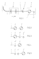
- a casting-rolling plant is sketched, which is designed as a full-Konti plant and which includes a casting machine 2 and a rolling mill 3 as central elements.
- the rolling mill 3 In the conveying direction F behind the casting machine 2, the rolling mill 3 is arranged, which may also be a roughing mill and a downstream finishing mill. Commonly used furnace equipment and cooling systems are not shown. Behind the rolling mill 3 is a flying shears 5. In the conveying direction F then closes a Coiler 4 on. With the system, a band 1 can be made, which is wound in the coiler 4 to form a coil.
- the reeling device 4 comprises at least two rotor reels 4 'or at least one rotor reel 4' and at least one underfloor reel 4 ".
- the rotor reel 4 ' is provided for the winding of a strip 1 with a thickness of less than 0.7 mm.
- Fig. 1 is a first embodiment to see, in which the reeling device 4, first a single rotor reel 4 'and then a single underfloor reel 4 "has.
- FIGS. 2 to 5 For this purpose, alternative embodiments can be seen.
- the reeling device 4 has two rotor reels 4 'following one another in the conveying direction.
- the reel device 4 has according to the embodiment Fig. 3 first a rotor reel 4 ', to which two underfloor reels 4 "connect.
- Fig. 5 provided that initially two Unterflurhaspeln 4 "are present, to which in the conveying direction F a rotor reel 4 'is connected.
- a tape 1 can be rewound from a rotor reel 4 'if its thickness is between 0.6 and 0.8 mm.
Landscapes
- Engineering & Computer Science (AREA)
- Mechanical Engineering (AREA)
- Metal Rolling (AREA)
Applications Claiming Priority (2)
| Application Number | Priority Date | Filing Date | Title |
|---|---|---|---|
| DE102013225056 | 2013-12-05 | ||
| DE102014213537.0A DE102014213537A1 (de) | 2013-12-05 | 2014-07-11 | Verfahren und Vorrichtung zur Herstellung eines metallischen Bandes im Gießwalzverfahren |
Publications (1)
| Publication Number | Publication Date |
|---|---|
| EP2881185A1 true EP2881185A1 (fr) | 2015-06-10 |
Family
ID=51900120
Family Applications (1)
| Application Number | Title | Priority Date | Filing Date |
|---|---|---|---|
| EP14191404.4A Withdrawn EP2881185A1 (fr) | 2013-12-05 | 2014-11-03 | Procédé et dispositif de fabrication d'une bande métallique dans le cadre du procédé de laminage |
Country Status (2)
| Country | Link |
|---|---|
| EP (1) | EP2881185A1 (fr) |
| DE (1) | DE102014213537A1 (fr) |
Cited By (2)
| Publication number | Priority date | Publication date | Assignee | Title |
|---|---|---|---|---|
| WO2017036769A1 (fr) * | 2015-08-28 | 2017-03-09 | Sms Group Gmbh | Installation fonctionnant suivant le concept csp (compact strip production) et procédé de fonctionnement d'une telle installation |
| CN108788934A (zh) * | 2017-05-03 | 2018-11-13 | 马勒国际有限公司 | 用于制造和切割平坦金属的无端元件的生产设备和方法 |
Citations (6)
| Publication number | Priority date | Publication date | Assignee | Title |
|---|---|---|---|---|
| WO1999025501A1 (fr) | 1997-11-14 | 1999-05-27 | Mannesmann Ag | Dispositifs enrouleurs pour enrouler une bande mince laminee |
| EP1016471A1 (fr) | 1997-11-11 | 2000-07-05 | Ishikawajima-Harima Heavy Industries Co., Ltd. | Equipement de reception de matieres laminees a chaud et procede de reception |
| EP1003617B1 (fr) | 1997-08-15 | 2001-12-12 | SMS Demag AG | Enrouleuse rotorique |
| WO2003013750A2 (fr) * | 2001-08-07 | 2003-02-20 | Sms Demag Aktiengesellschaft | Installation de laminage a chaud |
| DE69928559T2 (de) | 1999-03-25 | 2006-06-01 | Jfe Steel Corp. | Verfahren zum wickeln von band |
| DE60307496T2 (de) | 2002-09-19 | 2007-08-23 | Giovanni Arvedi | Prozess- und produktionslinie zur herstellung von ultradünnen heissgewalzten streifen auf grundlage der dünnbrammentechnik |
-
2014
- 2014-07-11 DE DE102014213537.0A patent/DE102014213537A1/de not_active Withdrawn
- 2014-11-03 EP EP14191404.4A patent/EP2881185A1/fr not_active Withdrawn
Patent Citations (6)
| Publication number | Priority date | Publication date | Assignee | Title |
|---|---|---|---|---|
| EP1003617B1 (fr) | 1997-08-15 | 2001-12-12 | SMS Demag AG | Enrouleuse rotorique |
| EP1016471A1 (fr) | 1997-11-11 | 2000-07-05 | Ishikawajima-Harima Heavy Industries Co., Ltd. | Equipement de reception de matieres laminees a chaud et procede de reception |
| WO1999025501A1 (fr) | 1997-11-14 | 1999-05-27 | Mannesmann Ag | Dispositifs enrouleurs pour enrouler une bande mince laminee |
| DE69928559T2 (de) | 1999-03-25 | 2006-06-01 | Jfe Steel Corp. | Verfahren zum wickeln von band |
| WO2003013750A2 (fr) * | 2001-08-07 | 2003-02-20 | Sms Demag Aktiengesellschaft | Installation de laminage a chaud |
| DE60307496T2 (de) | 2002-09-19 | 2007-08-23 | Giovanni Arvedi | Prozess- und produktionslinie zur herstellung von ultradünnen heissgewalzten streifen auf grundlage der dünnbrammentechnik |
Non-Patent Citations (3)
| Title |
|---|
| "Die neue Giesswalzanlage", 31 October 1999 (1999-10-31), XP055179645, Retrieved from the Internet <URL:http://www.ewp.rpi.edu/hartford/~ernesto/S2004/CHT/Figures/thyssenkrupp.pdf> [retrieved on 20150326] * |
| GROOT J ET AL: "NEW HOT ROLLING TECHNOLOGY FOR THIN STRIP ROLLING IN A DIRECT SHEET PLANT//NEUES VERFAHREN ZUM WARMWALZEN VON BAENDERN AUS DUENNBRAMMEN", STAHL UND EISEN, VERLAG STAHLEISEN, DUSSELDORF, DE, vol. 124, no. 2, 16 February 2004 (2004-02-16), pages 45 - 50, XP001046811, ISSN: 0340-4803 * |
| MARKOV Z M ET AL: "ZWEIWALZENMETHODE UND-ANLAGE ZUR ERZEUGUNG MIKROKRISTALLINER UND AMORPHER METALLBAENDER DIREKT AUS DER SCHMELZE", ELEKTRIE, VEB VERLAG TECHNIK. BERLIN, DD, vol. 48, no. 1, 1 January 1994 (1994-01-01), pages 18,23 - 25, XP000443094, ISSN: 0013-5399 * |
Cited By (2)
| Publication number | Priority date | Publication date | Assignee | Title |
|---|---|---|---|---|
| WO2017036769A1 (fr) * | 2015-08-28 | 2017-03-09 | Sms Group Gmbh | Installation fonctionnant suivant le concept csp (compact strip production) et procédé de fonctionnement d'une telle installation |
| CN108788934A (zh) * | 2017-05-03 | 2018-11-13 | 马勒国际有限公司 | 用于制造和切割平坦金属的无端元件的生产设备和方法 |
Also Published As
| Publication number | Publication date |
|---|---|
| DE102014213537A1 (de) | 2015-06-11 |
Similar Documents
| Publication | Publication Date | Title |
|---|---|---|
| DE3241745C2 (de) | Verfahren zum Herstellen von warmgewalztem Stahlband aus stranggegossenem Vormaterial in unmittelbar aufeinanderfolgenden Arbeitsschritten | |
| WO1989011363A1 (fr) | Procede pour produire en continu du feuillard d'acier ou de la tole d'acier a partir de produits plats fabriques selon le procede de coulee continue en arc | |
| DE2256030A1 (de) | Verfahren und vorrichtung zum walzen von heissen metallwerkstuecken sowie aufwickler zur anwendung beim aufwickeln von heissen metallwerkstuecken | |
| DE69507729T2 (de) | Verfahren zur Herstellung von Bandstahl, ausgehend von dünnen Bramen, und entsprechende Anlage | |
| EP4031457B1 (fr) | Retrait automatisé de la sangle d'une bobine | |
| DE69410562T2 (de) | Verfahren zum Walzen und Schneiden eines kontinuierlich warmgewalzten Stahlbandes | |
| DE60109846T2 (de) | Verfahren und Anlage zum Kaltwalzen | |
| DE69909332T2 (de) | Integriertes kontinuierliches stranggiess- und inline warmwalzverfahren sowie entsprechendes verfahren mit zwischenwickeln und abwickeln des vorstreifens | |
| DE102008009916A1 (de) | Walzanlage zum Walzen von bandförmigem Walzgut | |
| WO2017036769A1 (fr) | Installation fonctionnant suivant le concept csp (compact strip production) et procédé de fonctionnement d'une telle installation | |
| EP4323145B1 (fr) | Procédé de fabrication de fibres métalliques, plus particulièrement de fibres d'acier | |
| DE102015210863A1 (de) | Gieß-Walz-Anlage und Verfahren zu deren Betrieb | |
| EP2881185A1 (fr) | Procédé et dispositif de fabrication d'une bande métallique dans le cadre du procédé de laminage | |
| DE102013214939A1 (de) | Gießwalzanlage zum Herstellen von Metallbändern | |
| DE1602371A1 (de) | Verfahren zum Herstellen eines laenglichen Produktes,wie eines Drahtes,eines Kabels oder einer Stange,aus Kohlenstoffstahl,mit hoher Bruch- und Dehnungsfestigkeit,sowie nach diesem Verfahren hergestellte Produkte | |
| DE102011078150A1 (de) | Verfahren, Computerprogramm und Walzstraße zum Walzen eines Metallbandes | |
| DE102013214940A1 (de) | Gießwalzanlage und Verfahren zum Herstellen von Brammen | |
| DE19513999C2 (de) | Fertigungslinie und deren Verwendung zum Herstellen von Stahlband | |
| EP0449004A2 (fr) | Procédé et installation pour la fabrication de bandes laminées à chaud, en particulier pour aciers spéciaux À partir d'une ébauche en forme de bande coulée en continu | |
| EP3099432B1 (fr) | Procédé et dispositif d'échantillonnage de bandes métalliques | |
| DE102018207026A1 (de) | Multiflexible Walzanlage | |
| DE102013108184B3 (de) | Wickelmaschine und Verfahren zum Herstellen von Drahtkernen für Fahrzeugreifen | |
| DE20117301U1 (de) | Vorrichtung für die Herstellung metallener Flachbandleiter | |
| AT511674B1 (de) | Inbetriebnahme einer fertigwalzstrasse in einer giess-walz-verbundanlage | |
| EP1107834A1 (fr) | Procede et installation de production de larges feuillards a chaud, notamment de brames minces |
Legal Events
| Date | Code | Title | Description |
|---|---|---|---|
| PUAI | Public reference made under article 153(3) epc to a published international application that has entered the european phase |
Free format text: ORIGINAL CODE: 0009012 |
|
| 17P | Request for examination filed |
Effective date: 20141103 |
|
| AK | Designated contracting states |
Kind code of ref document: A1 Designated state(s): AL AT BE BG CH CY CZ DE DK EE ES FI FR GB GR HR HU IE IS IT LI LT LU LV MC MK MT NL NO PL PT RO RS SE SI SK SM TR |
|
| AX | Request for extension of the european patent |
Extension state: BA ME |
|
| RAP1 | Party data changed (applicant data changed or rights of an application transferred) |
Owner name: SMS GROUP GMBH |
|
| 17Q | First examination report despatched |
Effective date: 20150722 |
|
| RBV | Designated contracting states (corrected) |
Designated state(s): AL AT BE BG CH CY CZ DE DK EE ES FI FR GB GR HR HU IE IS IT LI LT LU LV MC MK MT NL NO PL PT RO RS SE SI SK SM TR |
|
| STAA | Information on the status of an ep patent application or granted ep patent |
Free format text: STATUS: THE APPLICATION HAS BEEN WITHDRAWN |
|
| 18W | Application withdrawn |
Effective date: 20190524 |